CIM LAB MECHANICAL / VI SEM 1 COMPUTER INTEGRATED MANUFACTURING LABORATORY (14AME31) (For III B.Tech - II SEM- Mechanical Engineering) DEPARTMENT OF MECHANICAL ENGINEERING SRI VENKATESWARA COLLEGE OF ENGINEERING & TECHNOLOGY R.V.S NAGAR, CHITTOOR-517127
Transcript
CIM LAB MECHANICAL / VI SEM
1
COMPUTER INTEGRATED MANUFACTURING
LABORATORY
(14AME31)
(For III B.Tech - II SEM- Mechanical Engineering)
DEPARTMENT OF MECHANICAL ENGINEERING
SRI VENKATESWARA COLLEGE OF ENGINEERING
& TECHNOLOGY
R.V.S NAGAR, CHITTOOR-517127
CIM LAB MECHANICAL / VI SEM
2
CONTENTS
S. No.
TITLE
PAGE NO.
1 SYLLABUS 3
2 GENERAL INSTRUCTIONS 4
3 LIST OF EXPERIMENTS 5
CNC LATHE 6
CNC MILLING 23
ROBOT PROGRAMMING 37
4 APPENDIX 40
CIM LAB MECHANICAL / VI SEM
3
SYLLABUS
CIM LAB MECHANICAL / VI SEM
4
GENERAL INSTRUCTIONS
1. Students should wear the uniform and closed foot wear. Students inappropriately dressed for lab,
at the instructor’s discretion, are denied access.
2. Eating, drinking and smoking are prohibited in the laboratory at all times.
3. Never work in the laboratory without proper supervision by an instructor.
4. Never carry out unauthorized experiments. Come to the laboratory prepared. If you are unsure
about what to do, please ask the instructor.
5. Except the scientific calculator, any other electronic devices are not permitted to use inside the
Laboratory.
6. Any damage to any of the equipment/instrument/machine caused due to carelessness, the cost
will be fully recovered from the individual (or) group of students.
CIM LAB MECHANICAL / VI SEM
5
LIST OF EXPERIMENTS
S. No.
NAME OF THE EXPERIMENT
PAGE
No.
DATE
OF Exp.
FACULTY
SIGNATURE
CNC LATHE OPERATIONS
1 FACING CYCLE 7
2 TURNING CYCLE 9
3 STEP TURNING 11
4 TAPER TURNING 13
5 TURNING - CIRCULAR INTERPOLATION 15
6 THREADING 17
7 GROOVING 21
CNC MILLING OPERATIONS
8 LINEAR AND CIRCULAR INTERPOLATION
24
9 ENGRAVING
26
10 MIRRORING
29
11 ROTATION
31
12 CIRCULAR POCKETING
33
13 RECTANGULAR POCKETING
35
ROBOT PROGRAMING
14 ROBOT PROGRAMING 1
38
15 ROBOT PROGRAMING 2
39
CIM LAB MECHANICAL / VI SEM
6
CIM LAB MECHANICAL / VI SEM
7
FACING CYCLE
Experiment No: Date:
AIM : To write a program to obtain the facing cycle in the CNC lathe.
EQUIPMENT REQUIRED: CNC Lathe
PROGRAM :
[BILLET X25 Z70] (Size of the Specimen)
G21 G98;
G28 U0W0;
M06 T1;(Facing Tool)
M03 S1200;
G00 X26 Z0;
G94 X0 Z-0.5 F50;
Z-1.0
Z-1.5
Z-2.0
Z-2.5
Z-3.0
Z-3.5
Z-4.0
Z-4.5
Z-5.0
Z-5.5
Z-6.0
Z-6.5
Z-7.0
Z-7.5
CIM LAB MECHANICAL / VI SEM
8
Z-8.0
Z-8.5
Z-9.0
Z-9.5
Z-10.0
G28 U0W0;
M05;
M30;
SKETCH :
RESULT:
CIM LAB MECHANICAL / VI SEM
9
TURNING CYCLE
Experiment No: Date:
AIM: To write a program to obtain the turning cycle in the CNC lathe.
SOFTWARE REQUIRED: CNC Lathe Software with FANUC Language.
PROGRAM:
[BILLET X28 Z70] (Size of the Specimen)
G21 G98;
G28 U0W0;
M06 T1; (Facing Tool)
M03 S1000;
G00 X25 Z1;
G90 X24 Z-45 F50;
X23;
X22;
X21;
X20;
G28 U0W0;
M05;
M30;
CIM LAB MECHANICAL / VI SEM
10
SKETCH :
RESULT:
CIM LAB MECHANICAL / VI SEM
11
STEP TURNING
Experiment No: Date:
AIM: To write a program to obtain the step turning cycle in the CNC lathe.
SOFTWARE REQUIRED: CNC Lathe Software with FANUC Language.
PROGRAM:
[BILLET X28 Z70] (Size of the Specimen)
G21 G98;
G28 U0W0;
M06 T1; (Facing Tool)
M03 S1000;
G00 X25 Z1;
G90 X24 Z-45 F50;
X23;
X22;
X21;
X20;
X19 Z-40;
X18;
X17;
X16;
X15;
X14 Z-20;
X13;
X12;
X11;
X10;
CIM LAB MECHANICAL / VI SEM
12
G28 U0W0;
M05;
M30;
SKETCH:
RESULT:
CIM LAB MECHANICAL / VI SEM
13
TAPER TURNING
Experiment No: Date:
AIM: To write a program to obtain the taper turning cycle in the CNC lathe.
SOFTWARE REQUIRED: CNC Lathe Software with FANUC Language.
PROGRAM:
[BILLET X28 Z70] (Size of the Specimen)
G21 G98;
G28 U0W0;
M06 T1; ( Turning Tool)
M03 S1000;
G00 X25 Z1;
G90 X24 Z-45 F50;
X20 Z-45 F50;
G28 U0W0;
M05;
M30;
CIM LAB MECHANICAL / VI SEM
14
SKETCH:
TAPER TURNING CYCLE
RESULT:
CIM LAB MECHANICAL / VI SEM
15
TURNING - CIRCULAR INTERPOLATION
Experiment No: Date:
AIM: To write a program to obtain the Circular Interpolation in the CNC lathe.
SOFTWARE REQUIRED: CNC Lathe Software with FANUC Language.
PROGRAM:
[BILLET X62 Z70] (Size of the Specimen)
G21 G98;
G28 U0W0;
M06 T1;(Facing Tool)
G00 X13 Z1;
G94 X0 Z-0.5 F50;
Z-1.0;
G71 U0.5 R1;
G71 P10 Q20 U0.1 W0.1 F50;
N10 G01 X05;
G01 Z-1.0;
G01 X15 Z-2;
G01 X15 Z-12;
G03 X20 Z-17 R5;
G01 X20 Z-22;
N20 G02 X25 Z-27 R5;
G28 U0W0;
M05;
CIM LAB MECHANICAL / VI SEM
16
M30;
SKETCH:
CIM LAB MECHANICAL / VI SEM
17
RESULT:
DRILLING CYCLE
Experiment No: Date:
AIM: To write a program to obtain the Drilling Cycle in the CNC lathe.
SOFTWARE REQUIRED: CNC Lathe Software with FANUC Language.
PROGRAM:
[BILLET X25 Z70] (Size of the Specimen)
G21 G98;
G28 U0W0;
M06 T2;(Center Drill Dia. 3 mm)
M03 S1000;
G00 X0 Z1;
G74 R1;
G74 X0 Z-25 Q500 F30;
G28 U0 W0;
M06 T4; (Drill Dia. 10 mm)
G00 X0 Z1;
G74 R1;
G74 X0 Z-20 Q500 F30;
G28 U0 W0;
M06 T6; (Drill Dia. 12 mm)
G00 X0 Z1;
G74 R1;
CIM LAB MECHANICAL / VI SEM
18
G74 X0 Z-10 Q500 F30;
G28 U0W0;
M05;
M30;
SKETCH:
CIM LAB MECHANICAL / VI SEM
19
RESULT:
THREADING CYCLE
Experiment No: Date:
AIM: To write a program to obtain the Threading Cycle in the CNC lathe.
SOFTWARE REQUIRED: CNC Lathe Software with FANUC Language.
PROGRAM:
[BILLET X25 Z70] (Size of the Specimen)
G21 G98;
G28 U0W0;
M06 T1; (Threading Tool)
M03 S600;
G00 X26 Z0;
G76 P021560 Q50 R0.1;
G76 X23.774 Z-25 P613 Q100 F1;
G28 U0W0;
M05;
M30;
CIM LAB MECHANICAL / VI SEM
20
SKETCH:
CIM LAB MECHANICAL / VI SEM
21
RESULT:
GROOVING CYCLE
Experiment No: Date:
AIM: To write a program to obtain the Grooving Cycle in the CNC lathe.
SOFTWARE REQUIRED: CNC Lathe Software with FANUC Language.
PROGRAM:
[BILLET X25 Z70] (Size of the Specimen)
G21 G98;
G28 U0W0;
M06 T1;( Facing Cycle)
M03 S1000;
G00 X26 Z0;
G94 X0 Z-0.5 F50;
Z-1.0;
Z-1.5;
G28 U0W0;
G00 X26Z0;
G90 X26Z0;
G90 X25 Z-36.5 F30;
X24;
X23;
CIM LAB MECHANICAL / VI SEM
22
G28 U0W0;
M06 T3; (Grooving Tool)
G00 X24 Z-13.5;
G75 R1;
G75 X70 Z-31.5 P200 Q1000 F30;
G28 U0W0;
M05;
M30;
SKETCH:
CIM LAB MECHANICAL / VI SEM
23
RESULT:
CIM LAB MECHANICAL / VI SEM
24
LINEAR AND CIRCULAR INTERPOLATION
Experiment No: Date:
AIM: To write a program to obtain linear and circular interpolation on the given work piece.
SOFTWARE REQUIRED: CNC XMILL Software with FANUC Language.
PROGRAM:
G21 G94
G91 G28 Z0
G28 X0 Y0
M06 T06
M03 S1300
G90 G00 X0 Y0 Z5
G90 G01 X0 Y0
X30
G03 X54 R12
G01 X82
G02 X108 R13
G01 X123
X80 Y45
CIM LAB MECHANICAL / VI SEM
25
X40
Y75
G03 X35 Y80 R5
G01 X20
G03 X0 Y80 R10
G01 Y0
M30
SKETCH:
LINEAR AND CIRCULAR INTERPOLATION
CIM LAB MECHANICAL / VI SEM
26
RESULT:
ENGRAVING OF LETTERS
Experiment No: Date:
AIM: To write a program to engrave the letters “SVCET” on the given work piece.
SOFTWARE REQUIRED: CNC XMILL Software with FANUC Language.
PROGRAM:
G21 G94
G91 G28 Z0
G28 X0 Y0
M06 T06
M03 S1300
G90 G00 X0 Y0 Z5
[S]
G00 X2 Y30
G01 Z-1 F60
G01 X10 Y30
G03 X15 Y35 R5
G01 X15 Y 37.5
G03 X10 Y42.5 R5
CIM LAB MECHANICAL / VI SEM
27
G01 X07 Y42.5
G02 X2 Y47.5 R5
G01 X2 Y50
G02 X7 Y55 R5
G01 X15 Y55
G00 Z2
[V]
G00 X20 Y55
G01 Z-1 F60
G01 X27.5 Y30
G01 X33 Y55
G00 Z2
[C]
G00 X51 Y55
G01 Z-1 F60
G01 X43 Y55
G03 X38 Y50 R5
G01 X38 Y35
G03 X43 Y30 R5
G01 X51 Y30
G00 Z2
[E]
G00 X69 Y55
G01 Z-1F60
G01 X56 Y55
G01 X56 Y42.5
G01 X69 Y42.5
G01 X56 Y42.5
G01 X56 Y30
G01 X69 Y30
G00 Z2
[T]
G00 X81.5 Y30
CIM LAB MECHANICAL / VI SEM
28
G01 Z-1 F60
G01 X81.5 Y55
G01 X74 Y55
G01 X87 Y55
G00 Z2
G91 G28 Z0
G28 X0Y0
M05
M30
SKETCH:
ENGRAVING OF LETTERS
CIM LAB MECHANICAL / VI SEM
29
RESULT:
MIRRORING
Experiment No: Date:
AIM: To write a program to perform the mirroring operation.
SOFTWARE REQUIRED: CNC XMILL Software with FANUC Language.
PROGRAM:
G21 G94
G91 G28 Z0
G28 X0 Y0
M06 T06
M03 S1500
G90 G00 X0 Y0 Z5
M98 P4646
M70
M98 P4646
M80
M70
M71
M98 P4646
CIM LAB MECHANICAL / VI SEM
30
M80
M81
M71
M98 P4646
M81
G91 G28 Z0
G28 X0 Y0
M05
M30
O4646
G00 X10 Y10
G01 Z-1.5 F80
G01 X30 Y10
G03 X10 Y30 R20
G01 X10 Y10
G00 Z5
M99
SKETCH:
MIRRORING
CIM LAB MECHANICAL / VI SEM
31
RESULT:
ROTATION
Experiment No: Date:
AIM: To write a program to perform the Rotation operation on the given work piece.
SOFTWARE REQUIRED: CNC XMILL Software with FANUC Language.
PROGRAM:
G21 G94
G91 G28 Z0
G28 X0 Y0
M06 T06
M03 S1300
G90 G00 X0Y0 Z5
M98 P1234
G68 X0Y0 R90
M98 P1234
G68 X0Y0 R180
M98 P1234
G68 X0Y0 R270
CIM LAB MECHANICAL / VI SEM
32
G69
G68 X0Y0 R360
G69
G91 G28 Z0
G28 X0Y0
M05
M30
O1234
G00 X0Y0
G01 Z-1 F60
G01 X20 Y-10
G01 X40 Y0
G01 X20 Y10
G01 X0 Y0
G00 Z5
M99
SKETCH:
CIM LAB MECHANICAL / VI SEM
33
ROTATION
RESULT:
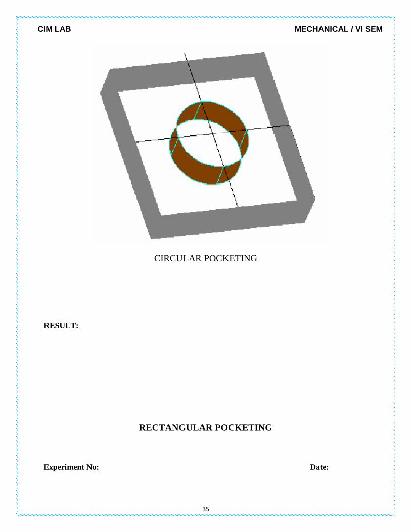
CIRCULAR POCKETING
Experiment No: Date:
AIM: To write a program to perform the Circular pocketing operation on the given work piece.
SOFTWARE REQUIRED: CNC XMILL Software with FANUC Language.
CIM LAB MECHANICAL / VI SEM
34
PROGRAM:
G21 G94
G91 G28 Z0
G28 X0Y0
M06 T05
M03 S1200
G90 G00X0 Y0 Z5
G170 R0 P0 Q1 X0 Y0 Z-10 I0.5 J0.1 K20
G171 P50 S1500 R60 F60 B1800 J100
G170 R0 P1 Q1 X0 Y0 Z-10 I0 J0 K20
G171 P50 S1500 R60 F60 B1800 J100
G00 Z5
M05
G91 G28 Z0
G28 X0 Y0
M30
SKETCH:
CIM LAB MECHANICAL / VI SEM
35
CIRCULAR POCKETING
RESULT:
RECTANGULAR POCKETING
Experiment No: Date:
CIM LAB MECHANICAL / VI SEM
36
AIM: To write a program to perform the Rectangular pocketing operation on the given work piece.
SOFTWARE REQUIRED: CNC XMILL Software with FANUC Language.
PROGRAM:
G21 G94
G91 G28 Z0
G28 X0 Y0
M06 T04
M03 S1200
G90 G00 X0 Y0 Z5
G172 I30 J30 K0 P0 Q1 R0 X-15 Y-15 Z-10
G173 I0.1 K0.1 P50 S1500 R60 F50 B1800 J100
G172 I30 J30 K0 P1 Q1 R0 X-15 Y-15 Z-10
G173 I0 K0 P50 S1500 R60 F50 B1800 J100
G00 Z5
M05
G91 G28 Z0
G28 X0 Y0
M30
SKETCH:
CIM LAB MECHANICAL / VI SEM
37
RECTANGULAR POCKETING
RESULT:
CIM LAB MECHANICAL / VI SEM
38
ROBOT PROGRAMING 1
Experiment No: Date:
CIM LAB MECHANICAL / VI SEM
39
AIM: To write and execute a robot program to perform a pick and place operation.
SOFTWARE REQUIRED: Pick and place robot integrated with system