144
Computer Numeric Control Polystyrene Cutter Christopher Adams Bachelor of Science in Computer Science with Honours The University of Bath May 2007
Computer Numeric Control Polystyrene Cutter
Christopher Adams
Bachelor of Science in Computer Science with HonoursThe University of Bath
May 2007
Computer Numeric Control Polystyrene
Cutter
Submitted by: Christopher Adams
COPYRIGHT
Attention is drawn to the fact that copyright of this dissertation rests with its author.The Intellectual Property Rights of the products produced as part of the project be-long to the University of Bath (see http://www.bath.ac.uk/ordinances/#intelprop).This copy of the dissertation has been supplied on condition that anyone who consultsit is understood to recognise that its copyright rests with its author and that noquotation from the dissertation and no information derived from it may be publishedwithout the prior written consent of the author.
Declaration
This dissertation is submitted to the University of Bath in accordance with the re-quirements of the degree of Bachelor of Science in the Department of ComputerScience. No portion of the work in this dissertation has been submitted in supportof an application for any other degree or qualification of this or any other universityor institution of learning. Except where specifically acknowledged, it is the work ofthe author.
Signed:

Abstract
Traditionally computer numeric control (CNC) polystyrene cutters rely on complexand expensive external hardware, this has made them financially nonviable for manymodellers. The project proposes a simpler and cheaper alternative to traditionalcutters. The project has developed a CNC polystyrene cutter using simple externalhardware. The solution was produced in JAVA and works on both Windows andLinux. The project concentrated on the synchronisation of the axes. The softwareto control the CNC cutter is able to produce model aircraft wings of various shapesand sizes, spar slots to strengthen the wings and blocks of polystyrene.

Acknowledgements
I would like to thank my supervisor Professor Nicolai Vorobjov for support and advicethroughout the project. I would also like to thank my mother and father for proofreading and constant support. In particular I would like to thank my brother forhelping design the hardware and electronics required to test the software. I wouldlike to thank my friend Rachel for her continuous support throughout the project.
ii
Contents
1 Introduction 1
1.1 The Problem . . . . . . . . . . . . . . . . . . . . . . . . . . . . . . . . 1
1.2 Project Aims . . . . . . . . . . . . . . . . . . . . . . . . . . . . . . . . 1
1.3 Dissertation Structure . . . . . . . . . . . . . . . . . . . . . . . . . . . 2
2 Literature Survey 3
2.1 CNC equipment . . . . . . . . . . . . . . . . . . . . . . . . . . . . . . . 4
2.1.1 What is a CNC polystyrene cutter? . . . . . . . . . . . . . . . 4
2.1.2 Uses . . . . . . . . . . . . . . . . . . . . . . . . . . . . . . . . . 4
2.1.3 Open loop and closed loop machine control . . . . . . . . . . . 4
2.1.4 Stepper Motors . . . . . . . . . . . . . . . . . . . . . . . . . . . 4
2.1.5 DC Motors and Encoders . . . . . . . . . . . . . . . . . . . . . 5
2.2 Existing Solutions . . . . . . . . . . . . . . . . . . . . . . . . . . . . . 6
2.2.1 Software . . . . . . . . . . . . . . . . . . . . . . . . . . . . . . . 6
2.2.2 Hardware . . . . . . . . . . . . . . . . . . . . . . . . . . . . . . 7
2.3 Available CNC hardware and software . . . . . . . . . . . . . . . . . . 7
2.3.1 Available Software . . . . . . . . . . . . . . . . . . . . . . . . . 7
2.3.2 Available Hardware . . . . . . . . . . . . . . . . . . . . . . . . 8
2.4 Ports Available . . . . . . . . . . . . . . . . . . . . . . . . . . . . . . . 8
2.4.1 Parallel Port . . . . . . . . . . . . . . . . . . . . . . . . . . . . 9
2.4.2 Serial . . . . . . . . . . . . . . . . . . . . . . . . . . . . . . . . 9
2.4.3 USB . . . . . . . . . . . . . . . . . . . . . . . . . . . . . . . . . 9
2.5 Synchronisation . . . . . . . . . . . . . . . . . . . . . . . . . . . . . . . 10
iii
2.5.1 Master Command Generator . . . . . . . . . . . . . . . . . . . 10
2.5.2 Master-slave controller . . . . . . . . . . . . . . . . . . . . . . . 10
2.5.3 Aerofoil construction . . . . . . . . . . . . . . . . . . . . . . . . 11
2.5.4 Length Based Synchronisation . . . . . . . . . . . . . . . . . . 11
2.5.5 Surface Based Synchronisation . . . . . . . . . . . . . . . . . . 12
2.6 Language Choice . . . . . . . . . . . . . . . . . . . . . . . . . . . . . . 15
2.6.1 .NET . . . . . . . . . . . . . . . . . . . . . . . . . . . . . . . . 15
2.6.2 C/C++ . . . . . . . . . . . . . . . . . . . . . . . . . . . . . . . 15
2.6.3 Java . . . . . . . . . . . . . . . . . . . . . . . . . . . . . . . . . 16
2.7 Conclusion . . . . . . . . . . . . . . . . . . . . . . . . . . . . . . . . . 16
3 Requirements Analysis and Specification 18
3.1 Introduction . . . . . . . . . . . . . . . . . . . . . . . . . . . . . . . . . 18
3.2 Requirements Capture . . . . . . . . . . . . . . . . . . . . . . . . . . . 18
3.3 Requirements Specification . . . . . . . . . . . . . . . . . . . . . . . . 19
3.4 Functional Requirements . . . . . . . . . . . . . . . . . . . . . . . . . . 20
3.4.1 Wing Cutting . . . . . . . . . . . . . . . . . . . . . . . . . . . . 20
3.4.2 Block Cutting . . . . . . . . . . . . . . . . . . . . . . . . . . . . 20
3.4.3 Spar Cutting . . . . . . . . . . . . . . . . . . . . . . . . . . . . 21
3.4.4 Other Features . . . . . . . . . . . . . . . . . . . . . . . . . . . 21
3.5 Non-functional Requirements . . . . . . . . . . . . . . . . . . . . . . . 21
3.5.1 Hardware . . . . . . . . . . . . . . . . . . . . . . . . . . . . . . 21
3.5.2 Compatibility . . . . . . . . . . . . . . . . . . . . . . . . . . . . 22
3.6 Scoping . . . . . . . . . . . . . . . . . . . . . . . . . . . . . . . . . . . 22
4 Design 24
4.1 Language Choice . . . . . . . . . . . . . . . . . . . . . . . . . . . . . . 24
4.2 User Interface Design . . . . . . . . . . . . . . . . . . . . . . . . . . . . 25
4.3 High Level Design . . . . . . . . . . . . . . . . . . . . . . . . . . . . . 26
4.3.1 Machine Setup . . . . . . . . . . . . . . . . . . . . . . . . . . . 26
4.3.2 Parallel Port Interaction . . . . . . . . . . . . . . . . . . . . . . 26
iv
4.3.3 Cutting . . . . . . . . . . . . . . . . . . . . . . . . . . . . . . . 27
4.3.4 Synchronisation . . . . . . . . . . . . . . . . . . . . . . . . . . . 28
4.3.5 Aerofoil Input . . . . . . . . . . . . . . . . . . . . . . . . . . . . 28
4.3.6 Count Generation . . . . . . . . . . . . . . . . . . . . . . . . . 29
4.3.7 Spar Cutting . . . . . . . . . . . . . . . . . . . . . . . . . . . . 30
4.3.8 Manual Motor Control . . . . . . . . . . . . . . . . . . . . . . . 30
4.4 Conclusion . . . . . . . . . . . . . . . . . . . . . . . . . . . . . . . . . 31
5 Detailed Design and Implementation 32
5.1 Introduction . . . . . . . . . . . . . . . . . . . . . . . . . . . . . . . . . 32
5.2 Technology’s Used . . . . . . . . . . . . . . . . . . . . . . . . . . . . . 32
5.2.1 Integrated Development Environment . . . . . . . . . . . . . . 32
5.2.2 Source Code Control . . . . . . . . . . . . . . . . . . . . . . . . 33
5.3 Implementation . . . . . . . . . . . . . . . . . . . . . . . . . . . . . . . 33
5.4 Aerofoil Input . . . . . . . . . . . . . . . . . . . . . . . . . . . . . . . . 33
5.5 Cutting Algorithm . . . . . . . . . . . . . . . . . . . . . . . . . . . . . 35
5.5.1 Possible solutions . . . . . . . . . . . . . . . . . . . . . . . . . . 36
5.5.2 The problem being solved . . . . . . . . . . . . . . . . . . . . . 36
5.5.3 Iterative Approach . . . . . . . . . . . . . . . . . . . . . . . . . 37
5.5.4 Recursive Approach . . . . . . . . . . . . . . . . . . . . . . . . 38
5.5.5 Waiting Approach . . . . . . . . . . . . . . . . . . . . . . . . . 39
5.6 Motor Control . . . . . . . . . . . . . . . . . . . . . . . . . . . . . . . 40
5.6.1 Motor Output . . . . . . . . . . . . . . . . . . . . . . . . . . . 40
5.6.2 Motor Controller . . . . . . . . . . . . . . . . . . . . . . . . . . 42
5.7 Motor Inputs . . . . . . . . . . . . . . . . . . . . . . . . . . . . . . . . 43
5.7.1 Parallel Port Inputs . . . . . . . . . . . . . . . . . . . . . . . . 44
5.7.2 Input Algorithm . . . . . . . . . . . . . . . . . . . . . . . . . . 44
5.8 Xfoil Integration . . . . . . . . . . . . . . . . . . . . . . . . . . . . . . 46
5.8.1 Operating System Dependence . . . . . . . . . . . . . . . . . . 46
5.8.2 Getting ready to run Xfoil . . . . . . . . . . . . . . . . . . . . . 47
5.8.3 Number of coordinates required . . . . . . . . . . . . . . . . . . 47
v
5.8.4 Coordinate generation . . . . . . . . . . . . . . . . . . . . . . . 48
5.8.5 Aerofoil Reconstruction . . . . . . . . . . . . . . . . . . . . . . 49
5.9 Synchronisation . . . . . . . . . . . . . . . . . . . . . . . . . . . . . . . 49
5.10 GUI . . . . . . . . . . . . . . . . . . . . . . . . . . . . . . . . . . . . . 51
6 System Testing 52
6.1 Hardware Used . . . . . . . . . . . . . . . . . . . . . . . . . . . . . . . 52
6.2 Validation Testing . . . . . . . . . . . . . . . . . . . . . . . . . . . . . 53
6.3 Defect Testing . . . . . . . . . . . . . . . . . . . . . . . . . . . . . . . 54
6.4 User Testing . . . . . . . . . . . . . . . . . . . . . . . . . . . . . . . . . 54
6.5 Conclusion . . . . . . . . . . . . . . . . . . . . . . . . . . . . . . . . . 54
7 Conclusion 55
7.1 Project Evaluation . . . . . . . . . . . . . . . . . . . . . . . . . . . . . 56
7.2 If the project was to run again . . . . . . . . . . . . . . . . . . . . . . 56
7.3 Further Work . . . . . . . . . . . . . . . . . . . . . . . . . . . . . . . . 57
7.3.1 Configurable Inputs and Outputs . . . . . . . . . . . . . . . . . 57
7.3.2 Synchronisation Extension . . . . . . . . . . . . . . . . . . . . . 57
7.3.3 Common Tasks . . . . . . . . . . . . . . . . . . . . . . . . . . . 57
A Electronics and Hardware 62
A.1 Requirements . . . . . . . . . . . . . . . . . . . . . . . . . . . . . . . . 62
A.1.1 Cutting hardware . . . . . . . . . . . . . . . . . . . . . . . . . . 62
A.1.2 Electronics . . . . . . . . . . . . . . . . . . . . . . . . . . . . . 62
A.1.3 Pin Layout . . . . . . . . . . . . . . . . . . . . . . . . . . . . . 63
A.2 Hardware Used . . . . . . . . . . . . . . . . . . . . . . . . . . . . . . . 64
A.3 Electronics Used . . . . . . . . . . . . . . . . . . . . . . . . . . . . . . 66
B User Interface Designs 70
B.1 Home GUI . . . . . . . . . . . . . . . . . . . . . . . . . . . . . . . . . 70
B.2 Select Wing Type . . . . . . . . . . . . . . . . . . . . . . . . . . . . . . 71
B.3 Straight Wing Setup . . . . . . . . . . . . . . . . . . . . . . . . . . . . 72
vi
B.4 Preview Cut . . . . . . . . . . . . . . . . . . . . . . . . . . . . . . . . . 73
B.5 Tapered Wing Setup . . . . . . . . . . . . . . . . . . . . . . . . . . . . 74
B.6 Import Aerofoil . . . . . . . . . . . . . . . . . . . . . . . . . . . . . . . 75
B.7 Available Aerofoils . . . . . . . . . . . . . . . . . . . . . . . . . . . . . 76
B.8 Machine Setup . . . . . . . . . . . . . . . . . . . . . . . . . . . . . . . 77
B.9 Block Cutting . . . . . . . . . . . . . . . . . . . . . . . . . . . . . . . . 78
C Testing 79
C.1 Functional Requirments Validation . . . . . . . . . . . . . . . . . . . . 79
C.2 Nonfunctional Requirments Validation . . . . . . . . . . . . . . . . . . 82
C.3 Defect Testing . . . . . . . . . . . . . . . . . . . . . . . . . . . . . . . 84
D Testing Results 87
D.1 Tapered Wing Photos . . . . . . . . . . . . . . . . . . . . . . . . . . . 87
D.2 Block Cutting Photos . . . . . . . . . . . . . . . . . . . . . . . . . . . 89
D.3 Spar Cutting Photos . . . . . . . . . . . . . . . . . . . . . . . . . . . . 91
D.4 Block Cutting . . . . . . . . . . . . . . . . . . . . . . . . . . . . . . . . 93
D.4.1 Normal Data . . . . . . . . . . . . . . . . . . . . . . . . . . . . 93
D.4.2 Extreme Data . . . . . . . . . . . . . . . . . . . . . . . . . . . . 94
D.4.3 Erroneous Data . . . . . . . . . . . . . . . . . . . . . . . . . . . 94
D.5 Spar Cutting . . . . . . . . . . . . . . . . . . . . . . . . . . . . . . . . 95
D.5.1 Normal Data . . . . . . . . . . . . . . . . . . . . . . . . . . . . 95
D.5.2 Extreme Data . . . . . . . . . . . . . . . . . . . . . . . . . . . . 96
D.5.3 Erroneous Data . . . . . . . . . . . . . . . . . . . . . . . . . . . 97
D.6 Synchronisation . . . . . . . . . . . . . . . . . . . . . . . . . . . . . . . 97
D.6.1 Length Synchronisation Coordinates . . . . . . . . . . . . . . . 97
D.6.2 Length Synchronisation Plot . . . . . . . . . . . . . . . . . . . 98
D.7 Surface Synchronisation . . . . . . . . . . . . . . . . . . . . . . . . . . 98
D.7.1 Surface Synchronisation Coordinates . . . . . . . . . . . . . . . 98
D.7.2 Surface Synchronisation Plot . . . . . . . . . . . . . . . . . . . 99
E Screen Shots 100
vii
E.1 Start Page . . . . . . . . . . . . . . . . . . . . . . . . . . . . . . . . . . 101
E.2 Select Wing Type . . . . . . . . . . . . . . . . . . . . . . . . . . . . . . 102
E.3 Straight Wing Cut . . . . . . . . . . . . . . . . . . . . . . . . . . . . . 103
E.4 Aerofoil Selection . . . . . . . . . . . . . . . . . . . . . . . . . . . . . . 104
E.5 Aerofoil Selection . . . . . . . . . . . . . . . . . . . . . . . . . . . . . . 105
E.6 Block Cutting . . . . . . . . . . . . . . . . . . . . . . . . . . . . . . . . 106
E.7 Spar Cutting . . . . . . . . . . . . . . . . . . . . . . . . . . . . . . . . 107
E.8 Machine Setup . . . . . . . . . . . . . . . . . . . . . . . . . . . . . . . 108
E.9 Manual Motor Control . . . . . . . . . . . . . . . . . . . . . . . . . . . 109
F Code 110
F.1 File: block Alg.java . . . . . . . . . . . . . . . . . . . . . . . . . . . . . 110
F.2 File: cut Alg4.java . . . . . . . . . . . . . . . . . . . . . . . . . . . . . 114
F.3 File: perimeter Foil.java . . . . . . . . . . . . . . . . . . . . . . . . . . 118
F.4 File: straight Cut.java . . . . . . . . . . . . . . . . . . . . . . . . . . . 120
F.5 File: perimeter Foil.java . . . . . . . . . . . . . . . . . . . . . . . . . . 122
F.6 File: motor Control.java . . . . . . . . . . . . . . . . . . . . . . . . . . 125
F.7 File: motor Driver.java . . . . . . . . . . . . . . . . . . . . . . . . . . . 128
F.8 File: input.java . . . . . . . . . . . . . . . . . . . . . . . . . . . . . . . 130
G The CD 134
viii
Chapter 1
Introduction
1.1 The Problem
Currently the cutting out of polystyrene wings for model aircraft requires two peopleto guide a hot wire around a template of an aerofoil section. This can cause problemsand inaccuracies as the two people operating the wire must be able to synchronise themovement of the wire around the template. The reason this is so difficult to achieveis because both people have to concentrate on the speed as well as the positioning ofthe wire. Also the templates need to be made extremely accurately if the resultingaerofoil is to be of the exact required shape. This means the cutting of aerofoils byhand is both time consuming and prone to error.
There are CNC machines, already in existence, which have the ability to cut outmodel aircraft wings. There is software to drive these machines such as FCut [1].These machines do however have one problem , which is that they rely on the useof stepper motors and also need complicated circuitry to make them work, both ofwhich can be very expensive. CNC polystyrene cutters are therefore financially outof reach for the majority of modellers. The machinery that is needed could howeverbe made relatively cheaply from easily available parts, if an inexpensive alternative tothe stepper motors and control circuitry could be found. The majority of modellerswho would like to use a CNC polystyrene cutter would then be able to afford theirown instead of having to rely on expensive commercially produced options.
1.2 Project Aims
The aim of this project is to produce software to control a CNC polystyrene cutterwhich uses simple external circuitary and inexpensive Direct Current (DC) motors.The hardware for the cutter was not developed as part of the project, however an
1
overview of the hardware that was used is available in Appendix A. The purpose ofthis dissertation is to investigate previous solutions and then design and develop anew solution using simple external hardware.
1.3 Dissertation Structure
The dissertation is split into multiple sections, each of these sections represent adifferent stage of the development. The first section is the literature survey, thisinvestigates existing solutions and researches the tools that are available to producethe solution. Chapter 3 deals with Requirements Analysis and Requirements Speci-fication, from the knowledge gained from the literature review the requirements aredeveloped and discussed. Chapter 4 deals with the Design of the software and thedecisions that had to be made. Chapter 5 discusses the low level design issues andimplementation issues. Chapter 6 identifies the techniques that were employed totest the software. The final chapter draws all the work together and identifies if theproject has been a success and how the project could be extended and improved.There are also various Appendices that are referenced throughput the dissertation.Before reading the dissertation it is advisable to read Appendix A in order to under-stand the hardware that was used when developing and testing the software.At theback of this dissertation there is a CD containing all the source code and instructionshow to run the developed program.
2
Chapter 2
Literature Survey
This literature survey proposes a new solution to the cutting of polystyrene wingsother than the existing Computer Numerical Control (CNC) cutters. Within thisproject there are areas such as the working of existing CNC cutters that need inves-tigation before the whole project can be understood. Many of the CNC machinesuse stepper motors, but these motors require complicated circuitry to control them.An understanding of the stepper motor circuitry is needed in order to understandthe existing solutions before alternatives can be developed. There are already inexistence many different software products to control CNC polystyrene cutters andthese need to be taken into account before an alternative solution can be formulated.It might be possible that one of the products could be adapted to use motors otherthat stepper motor, therefore eliminating the need to develop a solution from theground up.
Another area that needs investigation before development can start, is the availabletechnologies that can be employed and which of these technologies will be mostappropriate to use in the application domain. The program will need to interactwith a computers parallel port, therefore a language must be chosen that allowsaccess to the parallel port. With the current trend towards legacy free computers,the availability of the parallel port could be an issue. Investigation is needed tosee if any other ports could be used if the parallel port is not available. There arepossibilities of using existing programs to help the development of the application,if existing programs are used, then methods for interfacing with these programsneed to be investigated. There are many different standards of aerofoil input, theseneeds to be analysed to find the most appropriate for the application. One of themain obstacles to overcome in this project is the synchronisation of the 4 axes, thedifferent methods of synchronisation of these axes needs to be understood and anappropriate method employed.
3
2.1 CNC equipment
2.1.1 What is a CNC polystyrene cutter?
A CNC polystyrene cutter is a multi-axis machine that is used to cut polystyrene.This project concentrates on the uses of a CNC polystyrene cutter in the modelaircraft domain, therefore the use of the machinery in other domains will be ignored.
2.1.2 Uses
There are two main uses for a CNC polystyrene cutter in the model aircraft domainthese are:
• wing aerofoil cutting
• fuselage construction
Although these two uses are similar, they do vary in the shape of the item needingto be cut. This project will concentrate on aerofoil cutting and not fuselage cutting.
2.1.3 Open loop and closed loop machine control
In order to understand the different types of motors and control techniques used inCNC machines, it is necessary to undersand the basics of open and closed loop control.According to [2] open loop control is the simplest of the two techniques. In open loopcontrol, once a signal is sent there is no sensing device to confirm that the actionof the control signal has been carried out. A closed loop system differs in the factthat it has feedback to check that a requested operation has been carried out, whichgives a more precise control mechanism than open loop control. However in closedloop control each operation needs to be checked which increases the complexity of thesystem. Each method has its advantages, however a closed loop system is normallythe preferred method if a high level of accuracy is required.
2.1.4 Stepper Motors
According to [2] a stepper motor is a motor that converts electrical pulses intoproportional mechanical responses. This is ideally suited to open-loop systems whereprecise motion control is needed. According to [3] the control systems of open-loop stepper motors do have several shortcomings, including the missing of steps anddegradation of performance at high speeds. The main issue of these two shortcomingsis the possible missing of steps, which results in lower levels of accuracy. Accordingto [4] permanent magnet stepper motors can spontaneously reverse their direction
4
of rotaion, which can be a potential problem. No references mention this being aproblem in the existing CNC polystyrene cutters which use stepper motors, althoughthis could be a potential problem. The precise movement of a stepper motor iswhat makes them useful in CNC systems, the problem is that they require complexhardware to control their movement.
Unlike traditional DC motors it is not possible to just apply a voltage to a steppermotor and expect it to operate. A stepper motor must have specific inputs in orderto make the motor operate. According to [5] a stepper motor control system wouldneed the following components:
• A phase generator circuit to generate appropriately timed inputs to the steppermotor.
• A driver circuit to provide appropriate voltage and current levels to the steppermotor.
Where accurate control and a small step size are needed the electronic circuitrybecomes expensive. This paper illustrates that stepper motor control is indeed morecomplex and expensive than traditional DC motor control, however Stepper motorsdo have an advantage, in that they can be controlled more precisely than DC motorsin an open loop system.
2.1.5 DC Motors and Encoders
Unlike stepper motors, brushed DC motors have no method to control the amountthey turn. When a voltage is applied to a DC motor, the motor will continue toturn until the voltage is removed. In theory, if the voltage could be applied for veryprecise amounts of time, the amount of movement of the motor could be worked out,however this would still be very inaccurate and would vary depending on the loadon the motor. Servo motors do however exist, which according to [6] is simply aDC motor with a feedback loop. This means that the accuracy of the DC motor isincreased, but it does complicate the operation of the DC motor, as feedback controlis also required. This type of motor will be used in the CNC polystyrene cutter, as itreduces the amount of circuitry needed compared to a stepper motor, but increasesthe accuracy to an accepable level compared with DC motors without feedback.
5
2.2 Existing Solutions
2.2.1 Software
There are a number of existing software packages already available to operate CNCpolystyrene cutters, however they all use stepper motors. The software from [7] isprobably the most widely used software package. There are two versions available:
• GMFC PE which will only operate on windows 95/98/ME but will run on olderhardware.
• GMFC PRO which will run on most versions of windows, including95/98/ME/2000/XP.
The price for this software varies from 45 Euros for the PE version, to 150 Euros forthe PRO version. This software will only work with stepper motors and the associatedelectronics. GMFC is a French piece of software, although both the website andsoftware are available in an English version. The software is closed source, so thereis no possibility of modifying the software to work without stepper motors.
Another package that is widely used is [8]. This software package has undergonerapid development in the year of writing, and there have been six versions releasedup until the time of writing. This is a free piece of software, but must not be usedas commercial software. This software is also French, but has been translated intoEnglish, although one remaining problem is that the help file has not, as yet, beentranslated. The only solution if ’Help’ is required, is to translate the help section onthe website with a translater such as [9]. Although this software is free, it is not opensource, so can not be modified to work without stepper motors.
There is one additional piece of software that is of particular interest, this is [1].Development of this software started in September 2006. At the time of writing,development was still progressing rapidly, with frequent new releases. The reasonthis piece of software is interesting is because it is open source, which means it mightbe possible to modify the software to work without stepper motors. This piece ofsoftware was written in C# and requires the Microsoft .NET framework version2.0. There are however some potential problems with modifying this software forstandard DC motors, such problems include C# being platform dependent and thecurrent development rate of the software, each of these potential problems will belooked at in detail.
The previous program uses the .NET 2.0 framework and this is only available forwindows, meaning if it were to be modified, the solution would only work on windows.
6
There is however a potential solution to this problem, as there is a project working ondeveloping a .NET compatibility with operating systems other than windows whichis available from [10]. The mono project has support for .NET 1.1 but only haspatchy support for 2.0, which is a problem as FCut uses .NET 2.0. Although thisinitially looks like it could be a potential solution to the platform dependence issue, itis not, as it only has patchy support for .NET2.0. The other problem with modifyingFCut is the rate at which bugs are being found and fixed, which means that if FCutwas modified, all the modifications would need to be compatible with the bugfixessubsequently released. The number of bug fixes being released could be a majorproblem as the piece of software is still in the initial stages of development. For thesereasons it would not be viable to try to modify FCut to work with standard DCmotors.
2.2.2 Hardware
All of the programs mentioned rely on an electronic interface to control the steppermotors. Each of these pieces of software are designed to work with a 4 axes CNCpolystyrene cutter, therefore the control circuitry must be able to control 4 steppermotors simultaneously. There are kits available to build the required control boardwhich are available from [11]. This is not the only source of kits, but it is often thechosen one as the company has a good reputation for providing after sales support.All of these control boards connect to the computer using a standard parallel port.
2.3 Available CNC hardware and software
2.3.1 Available Software
There are already a number of software packages available that could be used tohelp with the development of a CNC polystyrene cutter. This section will evaluateeach of them to decide which would be the most benificial to use.
There is a program called Xfoil written by [12]. Xfoil is a program used to designand analyse subsonic aerofoils. This program which is, available under the GNUGeneral Public License, is available for windows precompiled and for other operatingsystems, the source code and compilation instructions are provided. Xfoil has somevery useful features which could be used in the development of a CNC polystyrenecutter. The most helpful of these, is the ability to increase the density of input pointsfor an airfoil. This is useful as an aerofoil may have a limited set of coordinates, andin order to cut a smooth wing, extra coordinates are required, a task which can bedifficult to achieve due to the complex shape of aerofoils. The program also has theability to specify the number and density of the points it generates. This program
7
will be very useful to use in the development of the CNC cutter, as the programoperates from the command line and it should not be hard to interact with it fromwithin the software developed.
There is another piece of potentially useful software called Profili [13]. Profilihas many uses, such as generating aerofoils from combinations of existing aerofoils,analysing aerofoil characteristics and it also has an aerofoil database. The mostrelevant feature for the project is the aerofoil database, as to cut an aerofoil the cutterneeds a set of coordinates. The database has over 2200 aerofoils and uses a MicrosoftAccess database, which means it would be possible to interface with the databasewithout the need to open the program. However Profili is not free software, so thedatabase could not be included with the CNC cutting program. Another interestingpoint is that Profili uses XFoil to generate extra points for its aerofoils. There isanother aerofoil database which could be used instead of Profili’s, it is produced bythe University of Illinois [14] this database has over 1550 aerofoils and is is availableunder the GNU General Public License. This database is available as a set of “.dat”files, each of the dat files is given the name of the corresponding aerofoil. Each datfile contains a set of coordinates for that aerofoil. This database will be very useful tointergrate into the CNC cutter software, so that a large selection of airfoils are easilyavailable quickly. The database developed by University of Illinous will be used, asit is available free of cost.
2.3.2 Available Hardware
The hardware that will be available will be in the form of a CNC polystyrenecutter with a simple electrical circuit to both turn the motors on and off. It will alsoincorporate a counter for each of these motors, to count the number of rotations.The counter will be used as a feedback loop, therefore making the system a closedloop system.
2.4 Ports Available
Throughtout the past few years the number of ports available on computers havebeen reducing. According to [15] the idea of legacy free computers was started by Intelwhen they sponsored a legacy free PC initiative. Part of the legcay free PC initiativewas to remove both Serial and Parallel ports in favour of Universal Serial Bus (USB)ports. There have been reasons for the elimination of legacy components, theseinclude lower power consumption, quieter fans and a reduction in price. This is theopinion of Intel, however [16] identifies that legacy components are both more difficultand problematic to install than their legacy free counterparts. A large proportion ofPCs produced today, as a consequence of this, lack parallel and serial ports, this is
8
especially true of laptops. Some desktop computers do still have parallel and serialports, but more recent machines tend not to have either. This means that it wouldbe useful to be able to produce a CNC cutter which does not use the parallel port.
2.4.1 Parallel Port
The parallel port is traditionally the port that has been used to control CNC polystyrenecutters. This is due to the relative ease of programing the parallel port in windows95/98. Now that windows 2000/XP has become more common, the use of the parallelport becomes more difficult as microsoft have prevented usermode access to IØportsfor security reasons, which means there is no longer direct access to the parallel port.There is however a program [17] which is available that makes it possible to programthe parallel port in the same way as before, in windows 95/98.
The parallel port has 25 pins. According to [5] the parallel port has 8 data lines, 5status lines and 4 bi-directional control lines. The 8 remaining pins are ground pins.
2.4.2 Serial
The serial port suffers from the same problem as the parallel port, in that it is notas common as it used to be. According to [18] the serial port was originally a 25 pinconnector, as opposed to the 9 pin connector found on computers now. According to[19] only 22 of the 25 pins are used in the 25 pin connector and most of the pins arenot needed for normal PC communication. The main limitation of the serial port isthat it sends and receives data one bit at a time over one wire. This is not an issuefor most applications, but for a CNC cutter which needs simultaneous control of thedifferent axes, it is an issue, as although the serial port could be used, additionalexternal hardware would be needed to interpret the different output signals. For thisreason the serial port will not be used to control the CNC polystyrene cutter.
2.4.3 USB
USB ports (version 1.1 and 2.0) are now the most common port available on mostcomputers, however there are potential problems in using them to control a CNCcutter. [20] states that the USB port’s purpose was to establish a unique interfacefor PC peripherals. In addition the cable layout is stated to be made up of four wires,V+,Ground, Data+ and Data-. There are far fewer wires than in both parallel andserial ports, which means the limited number of outputs would make it impossible touse a USB port to control a CNC polystyrene cutter without a need for complicatedexternal circuitry. Altough at first glance the use of USB looks unlikely, when it islooked at more closely, USB to parallel port adaptors are found to exist. However
9
these USB to parallel port adaptors do not work as a true parallel port does, whichmeans that they could not be used in the same way as a normall parallel port, thereis however a possibility that one of these could be used if an appropriate piece ofsoftware could be written to interface with the USB to parallel port adaptor.
The conclusion that has been drawn from the available ports, is that the parallelport will be the most appropriate port to use. However the possibility of also havingmodified code to work with a USB to Parallel port adaptor is worth considering, ifit is possible to achieve, as this would mean the cutter would work with legacy freecomputers. The use of a standard parallel port will be assumed for the rest of theliterature review, as if a program to interface with a USB to parallel adaptor can bewritten, it will be usable in the same way as a standard parallel port.
2.5 Synchronisation
One of the main issues with the CNC polystyrene cutter is the synchronisation ofall 4 of the axes while cutting an aerofoil. Various different techniques for this havebeen identified, the appropriateness of each of these techniques will be evaluatedin this section. Two different methods of synchronisation for machines that needto be position synchronised have been identified by [21] these are master commandgenerator and master-slave controller.
2.5.1 Master Command Generator
In this approach the commands for both axes are generated at the same discretetime points. This means that if the axes are tracking the position exactly, the syn-chronisation can be achieved. This approach also means that if one of the axis is inthe incorrect position, it is likely that the other axis will also be in the same relativeincorrect position.
2.5.2 Master-slave controller
In this approach one set of axes is designated the master axis and the other theslave axis, the master axis is given the trajectory to follow and the slave axis simplyfollows the route of the master axis. This is the simpler of the two techniques, asthere is no real synchronisation involved, as the slave axis is effectively just followingthe path of the master and therefore automatically synchronised. With this naiveinterpretation of the master slave approach, it would be impossible to have each axisfollow a different path. This approach could be modified to allow different paths inthe following way: if the master axis were to be given its path and the master axistold the slave axis where it should be on the slaves path. Such a modification however
10
effectively turns the master-slave approach into the the master command generator.The master command generator approach will be used in the CNC polystyrene cutter,due to the fact that each axis may require a different path.
2.5.3 Aerofoil construction
Often when a wing needs to be cut out, difficulties can occur if each end of thewing requires a different profile shape and size. This means that there will need to bea different number of points on the path of each of the profiles, which poses a majorproblem as the method of synchronising the two ends is not trivial. One has devisedtwo different techniques for achieving this: length based synchronisation and surfacebased synchronisation. Neither of these solutions is however perfect, as there areoften cases which will cause each of them to work incorrectly. Both of these methodshave been devised through tested different aerofoil sections and devising methods tosynchronise the cutting. The solution to this is explained below.
2.5.4 Length Based Synchronisation
With this technique, the synchronisation is based on the length of each of theaerofoils, which is the simpler of the two techniques, but would in most circumstancesresult in a lower quality output wing surface. This technique works in the followingway: the length of each aerofoil is taken and split into the same number of sections,at each of these section points a point is calculated on the surface of the aerofoil. Theaxis must start at point 0 on each aerofoil and must arrive at point 1 at the same time,which means that the cutting of the aerofoil will be synchronised. There are howeverproblems with this method, as this only takes into account the horizontal variationand not the vertical variation. Therefore if there is a section of the aerofoil thatgoes back on its self (very unlikely in reality) there will be a vast difference betweenthe distance each of the axes has to cover in the same amount of time therefore therequired speed of each set of axes will vary dramatically from section to section. Thisproblem is shown in Figure 2.1 between points 6 and 7 there is a vast differencebetween the lengths to be covered on the root and tip aerofoil. The method used toovercome this problem is illustrated in the surface based syncronisation. A bettermethod would be a system that takes into account the surface area of the aerofoils.
11
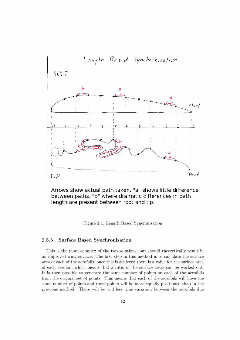
Figure 2.1: Length Based Syncronisation
2.5.5 Surface Based Synchronisation
This is the more complex of the two solutions, but should theoretically result inan improved wing surface. The first step in this method is to calculate the surfacearea of each of the aerofoils, once this is achieved there is a value for the surface areaof each aerofoil, which means that a ratio of the surface areas can be worked out.It is then possible to generate the same number of points on each of the aerofoilsfrom the original set of points. This means that each of the aerofoils will have thesame number of points and these points will be more equally positioned than in theprevious method. There will be will less time variation between the aerofoils due
12

to their being less extreme path lengths detween points, which should result in abetter wing surface, as this will allow for each section being cut in a similar time toall the other sections. There is also no problem if the wing surface goes back on itsself, as this will have been taken into account as part of the surface area calculation.Generally this is the better of the two solutions, however there will be still somesituations when the previous method is the better of the two techniques, an examplebeing when one of the aerofoils is a re-scaling of the other aerofoil. The surface basedsyncronisation is illustarted in Figure 2.2, this shows how the solution imporves uponthe length based syncronisation.
13
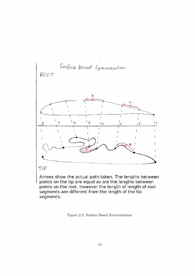
Figure 2.2: Surface Based Syncronisation
14
As each of these synchronisation methods has its advantages, it will be beneficial ifthe program allows for both methods to be used, with the user selecting the methodhe requires for a particular wing.
2.6 Language Choice
The requirements for this project specified that the software must work on Windowsand should also work under Linux, therefore a language that would allow the softwareto work on both of the platforms would be preferable, providing it will operate onWindows. There are many languages that could be used to write this software,although some of them will not meet the requirements of operating on both Windowsand Linux. There are all the normal issues of having a program that will run onboth Windows and Linux, due to the structure of the program, but for the CNCploystyrene cutter there is the additional issue of needing to interact directly withthe parallel port. This is a difficult issue to resolve as different platforms have differentways of interacting with the hardware, requiring a common way to interact with thehardware.
As has already been discussed, there is the dilemma that it is no longer possible todirectly interact with the parallel port in versions of Windows other than 9x. Thisproblem has already been solved using [17] when evaluating the most appropriatelanguage to use, it will be assumed that user port is used under Windows.
2.6.1 .NET
Microsoft’s .NET platform has recently gained popularity, however it is completelyplatform dependent. The Mono project has already been discussed as an attemptto make .NET platform independent. There is an additional effort called Rotor,highlighted by [22] which is an attempt by Microsoft to make .NET portable, thereare however some shortcomings, such as not all the .NET libraries being included.The library that would cause the most problems is ’System.Windows.Forms’ whichwould mean there would be no Graphical User Interface (GUI) support. The otherproblem that renders Rotor useless, is the fact that it does not support Linux, it onlysupports FreeBSD and OS X. For the reason of no platform independence the .NETplatform will be discounted as an option.
2.6.2 C/C++
C or C++ is a viable option to use to develop the CNC polystyrene cutter, howeverit is not as platform independent as Java. According to [23] C++ programs generallyrequire recompiling for use on different platforms. This would provide a program that
15
works with both Windows and Linux, however as the program will need direct accessto the parallel port, which is likely to cause issues, due to the different operatingsystems having different ways to access the hardware, C or C++ will not be used.
2.6.3 Java
Java has a package provided by Sun to allow one to interface with the parallel port,however there is also another package [24] which also allows the user to interfacewith the parallel port. This package is written with a combination of C and Javaand is accessed using the Java Native Interface (JNI). This package is available forboth Windows and Linux, therefore meeting the requirement of working on bothplatforms.
2.7 Conclusion
This literature review has arrived at several conclusions which will be discussed inthis section. The first conclusion concerns the type of motor and control techniquethat will be used. A standard DC motor with an encoder will be used, as thiseliminates the complex circuitry associated with stepper motors. This does meanthat a closed loop control technique will be required to incorporate an appropriatelevel of accuracy, as unlike stepper motors, it is very difficult to have an accurate DCmotor without checking its position.
The existing software solutions that are available have been analysed and one hasconcluded that none of these are appropriate to be adapted. The reasons for thisbeing that all the solutions analysed, with the exception of one, are closed source,meaning that the source code is unavailable and therefore making it impossible tomodify the program to work without stepper motors. The piece of software thatthe source code is available for, has problems that prevent it from being used. Themain problem that stops it from being used is that it is written in C# which usesthe .NET framework, which is not platform independent, thereby preventing it frombeing used as the solution should work on both Windows and Linux. The existinghardware that is available is designed to work with stepper motors, therefore it willnot work without them.
The existing programs which are available that could be used to help with thedevelopment of the CNC polystyrene cutter were analysed, and some of them werefound to be useful in the development of the project. The program XFoil was foundto be of use, as it has the ability to generate points for aerofoils when there are notenough points to produce a wing of a satisfactory standard. A database of aerofoilswas found which will be useful to include in the software, as it will provide a starting
16

point if a user wants to cut a wing and does not have the aerofoil available. Theprogram Profili was also highlighted as being of possible use, but as it is not availableat zero cost, it cannot be included with the developed program.
The available ports were analysed and a conclusion has been drawn. Althoughthe use of the parallel port is not ideal, because it is not available on legacy freecomputers, the project will use the parallel port, as it is the most appropriate portto use due to its high number of outputs. If time is available, and it is technicallypossible, a USB to parallel port option will also be included in the program.
The synchronisation problem was one of the main problems that the project en-countered, but a technique has been formulated that will be used to try to solvethe problem. Master commander approach has been chosen from the two controlmethods, as it will work better if there are different profiles at each end of the wing.One proposed two different techniques of synchronising the cutting of the aerofoil,and both of the methods will be included in the program as each will work well inparticular circumstances, but neither will work in all cases. The program will havethe option to select which method of synchronisation will be used, so that the usercan select the most appropriate for the task in hand.
Initially there were a number of languages that could have been chosen to producethe CNC polystyrene cutter, however further investigation showed that there wereissues which meant the language choice was more limited than first thought. Thelanguage that was finally chosen was JAVA, as it is platform independent and a par-allel port class exists that allows ways to access the parallel port from both Windowsand Linux.
17
Chapter 3
Requirements Analysis andSpecification
3.1 Introduction
The literature review has helped to obtain understand of previous solutions toCNC polystyrene cutting. The requirements analysis and specification will allow forspecification of what the developed solution will do, it will also scope the solutionso that some features will not be considered. In addition to this the requirementsanalysis will highlight the techniques that were used in order develop the requirementsand the techniques that were particularly successfully.
3.2 Requirements Capture
In order to specify the requirements, they first had to be captured. The processof capturing the requirements was conducted using available existing software anduser comments. The capture of requirements was also based on the findings of theliterature survey. This method was appropriate as the new solution would conductthe same sort of tasks as the previous software solutions, except in the way thatthe software performed the tasks. The main difference between the way the existingsolution works is that they rely on complex external circuitry, whereas the solutionbeing developed relies only on simple external circuitry.
In addition to capturing the requirements from the literature survey and existingsoftware, some of the requirements resulted from researching existing model aircraft.This proved to be very successful resource, as it enabled an understanding of the typeof wings required. This allowed the requirements to be developed so that the producedproduct would fulfil the required tasks. One of the requirements found from looking
18
at existing model aircraft wings and plans was that, although the majority of thetime a user will not have the actual aerofoil required, the plan that the model is builtfrom will often have the name of the aerofoil. This was an area of the requirementsanalysis that was particularly successful, as it produced a requirement which wouldmake the produced software more useful. One of the sources that was used and foundto be particularly useful, was a topic on a discussion board [25] which goes into detailabout the existing software products and user experience of most of the programs.Although this did not inspire any of the requirements directly, it proved to be ofgreat use as a general overview of existing solutions and problems.
3.3 Requirements Specification
The requirements specification has been separated into two subsections Functionalrequirements and Non-functional requirements. [26] specifies Functional requirementsas “statements of service the system should provide, how the system should react toparticular inputs and how the system should behave in particular situations” andNon-functional requirements as “constraints on the services or functions offered bythe system”.
The requirements use the key words “must”,“should” and “may”. These key wordsare used to indicate the importance of each of the requirements. The key word“Must” is the most important key word, indicating that the functionality is criticalto the product and the project will not be deemed successful if the functionality isnot provided. The key word “Should” means the requirement is necessary, but is notcritical to the success of the project, however the failure to achieve multiple “Should”requirements may mean the project is not deemed a success. The keyword “May”indicates that the requirement would ideally be included, but if not, will not resultin failure of the project.
Some of the requirements listed are particularly challenging to achieve. One of themost challenging is for the software to work on both Windows and Linux. At first thisseems easy to achieve, due to the platform independence of the JAVA programminglanguage, but it is actually more difficult as the parallel port driver used is differentin Windows and Linux. This is not the only difficulty with the requirement, anotherconcerns the integration of Xfoil with the developed software, as Xfoil needs to berun from a command prompt, different commands will be required for Windowsand Linux. For this reason the ability to run on Linux has been classified “should”instead of “must“. If this is successful it will result in a solution that runs on bothWindows and Linux, but is not truly platform independent. Another requirementthat is particularly taxing, is the ability to cut spars in the same pass as the cuttingof the wing. This is difficult because a spar can only be cut along the path that the
19
wire follows and no where else. This requirement has been included, although it onlyhas a ”may“ priority due to the problems associated with it.
3.4 Functional Requirements
The functional requirements are used to specify the functionality of the systemthat is required. The key words that have already been outlined have been used toidentify the importance of each of the requirements. The requirements have beensplit up into distinct sections to allow a better overview of the functionality of eachsection of the produced product.
3.4.1 Wing Cutting
1. The software must be able to cut wings with different type and size aerofoils ateach end.Description : This functionality is required in order to cut complex wings thatare sometimes needed.
2. Both ends of the cutter must run synchronised with each other.Description: This is required so that each end of the cutter is in the correctposition, relative to the other end, failure to do this would result in a wing withthe incorrect aerofoil section.
3. The software must be able to cut straight cored and tapered wings.Description: Straight cored wings are the simpler but tapered wings are oftenrequired, so it must be possible to cut both.
4. The software should be able to cut wings of different spans.Description: A wing of a different span will require different size aerofoils ateach end, if the wing is tapered.
3.4.2 Block Cutting
1. The software must be able to cut rectangular blocks of polystyrene for use inwing cutting.Description: This is required so that the user can cut the block of polystyreneto size, before starting the aerofoil cut.
2. The software should be able to cut blocks of polystyrene that are not rectangulare.g. triangular.Description: Some wings need blocks of polystyrene that are not rectangular.
20
3.4.3 Spar Cutting
1. The software must be able to cut spar slots after the wing has been cut out.Description: Wings often need spars to strengthen them and the cutting of theslots by hand is both difficult and time consuming.
2. The software may be able to cut out spar slots in the same pass, if the spar isparallel to the cutting wire during the cut.Description: This is a feature that is often requested, but is usually of limiteduse.
3.4.4 Other Features
1. The software must provide a method to manually move each of the axes.Description: Before a cut the user will want to be able to position the cuttingwire in the correct location and once the motors are attached to the axes itwould be impossible to move them by hand.
2. The software must have a selection of aerofoils built in to choose from, theaerofoils must have their relevant name displayed.Description: Most of the time users do not have the aerofoil coordinates theyrequire to hand, but they do often have the name of the aerofoil.
3. The software must provide a method for the user to manually import one oftheir own aerofoils.Description: Although the aerofoil database will be extensive, there will alwaysbe aerofoils the user requires that are not available, so they will need to beimported manually.
3.5 Non-functional Requirements
The non-functional requirements are used to specify constraints on how the systemmust provide the desired functionality. This has also been split into subsections sothat the constraints for each section are more defined.
3.5.1 Hardware
1. The machine must work with a simple circuit that can turn each motor on andoff and also reverse the direction of each motor.Description: This is the type of machine that will work with the softwareproduced.
21
2. The system must be able to use a counter on each axis to improve the accuracyof the cutting.Description: The accuracy of the system without a counter would be so poor,it would make the system unusable.
3. The software must be able to be configured to work with a variety of differentCNC foam cutting machines.Description: CNC cutting machines vary in size and design, so the softwaremust be able to work with a variety of different CNC cutting machines to beof use.
3.5.2 Compatibility
1. The software must work with a standard PC parallel port.Description: This is the only port available that allows the flexibility required.
2. The user interface must be usable by a computer literate user.Description: Users who would want to use the software would be familiar withcomputers, but may not be advanced users.
3. The software must work on PCs running Windows.Description: The majority of users who would want to use the software wouldbe running Windows.
4. The software should work on PCs running Linux.Description: Some users may require the software to run on Linux.
3.6 Scoping
This project has a potential vast amount of functionality, however the functionalityprovided needs to be scoped. Without scoping, the project will be too large to com-plete in the time available and the chances of failure would be high. The functionalitylisted below has not been considered in the development of the solution. Althoughthe functionality listed below would have been useful to have been included, it wasfelt that the software would perform the required task adequately, without this func-tionality.
One of the key requirements for the project is simple external circuitry, this led tothe scoping of the project listed below. The ability to vary the speed of the motorsand adjust the temperature of the cutting wire would require additional externalcircuitry, which would have violated non-functional requirement number 1. Thesepossible features were discounted for a number of reasons, the key reason being thatit was felt the scope of the project would be too large if they were included, and the
22
fact that they would violate one of the key requirements was also an important factorfor being discounted.
1. The speed of the motors will be fixed.Description: In order to vary the speed of stepper motors, the rate at which thesignals are sent to the motor is changed. To change the speed of a simple DCmotor the same approach can be applied, but a much higher switching frequencyis required, beyond that of the parallel port, for this reason the speed of themotors will be fixed by the input voltage to the motors.
2. The ability to vary the temperature of the hot wire.Description: Some of the existing solutions that are available provide a featureallowing the temperature of the wire to change during a cut, depending on thesection of the aerofoil which is being cut. This can improve the quality of thecut, if used in conjunction with varying the speed of the motors. As the speedof the motors is fixed throughout the cut there is no requirement for variablewire temperature.
3. The CNC polystyrene cutter will not work with USB to parallel port converters.Description: USB to parallel port adaptor’s emulate the parallel port, but donot allow direct hardware interaction, so will not work. It may be possibleto produce a driver to use a USB-parallel port adaptor, but this will not beconsidered.
23
Chapter 4
Design
The purpose of this chapter is to take the requirements that were developed in therequirements section and analysis them in order to develop a potential solution. Thedesign discussed in this chapter is at a high level, lower level design decisions will bediscussed in the Detailed Design chapter. The design of the user interface will alsobe included in this chapter.
4.1 Language Choice
The language choice was an area that posed particular problems. The problemsencountered were that the developed solution needed to be platform independentand, the nature of direct hardware interaction makes platform independence difficult.The solution is needed to work on both Windows and Linux, Sun provides the JavaCommunications 3.0 API [27] for the Java programming language, which has thepotential to offer a solution to platform independent access to the parallel port.There is however a problem in that the Java Communications 3.0 API only provideslimited access to the parallel port. After further investigation it was found thatthe use of Java Communications 3.0 API for interacting with the parallel port hassometimes in the past been troublesome [24]. While investigating the Sun solution,a third party solution was found. The solution is called Parport and is available [24]this solution provides access to the parallel port using the Java native interface, theunderlying code is written in C. Parport is available for both Windows and Linux,therefore solving the platform independence issue.
Another issue highlighted was the need to use Xfoil, which is a command lineoperated program, which could pose difficulties as the commands needed for Windowsand Linux would differ, however Java provides a class to find the operating systemname [28]. With the operating system name available it would be possible to execute
24
the correct code for the operating system in use. The system also needed a GUI,with Java a GUI can be generated with relative ease, the GUI that is developedis also platform independent. For the reasons highlighted and the general platformindependence of Java, the Java programming language was used to write the software.
4.2 User Interface Design
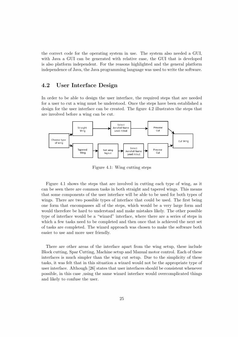
In order to be able to design the user interface, the required steps that are neededfor a user to cut a wing must be understood. Once the steps have been established adesign for the user interface can be created. The figure 4.2 illustrates the steps thatare involved before a wing can be cut.
Figure 4.1: Wing cutting steps
Figure 4.1 shows the steps that are involved in cutting each type of wing, as itcan be seen there are common tasks in both straight and tapered wings. This meansthat some components of the user interface will be able to be used for both types ofwings. There are two possible types of interface that could be used. The first beingone form that encompasses all of the steps, which would be a very large form andwould therefore be hard to understand and make mistakes likely. The other possibletype of interface would be a “wizard” interface, where there are a series of steps inwhich a few tasks need to be completed and then once that is achieved the next setof tasks are completed. The wizard approach was chosen to make the software botheasier to use and more user friendly.
There are other areas of the interface apart from the wing setup, these includeBlock cutting, Spar Cutting, Machine setup and Manual motor control. Each of theseinterfaces is much simpler than the wing cut setup. Due to the simplicity of thesetasks, it was felt that in this situation a wizard would not be the appropriate type ofuser interface. Although [26] states that user interfaces should be consistent wheneverpossible, in this case ,using the same wizard interface would overcomplicated thingsand likely to confuse the user.
25
It was decided that due to the number of user interfaces required it would be tootime consuming to hand code the interfaces. Instead of hand coding the interfacesthe Netbeans Intergrated Development Environment [29] would be used. Netbeanswas chosen as it can produce graphical interfaces with ease, although one additionallibrary is required to be included in the classpath, as the interfaces are generatedusing a non standard library.
The user interface designs are available in Appendix A. These show a rough designof the wizards that will be used to set up a wing to be cut, it also shows the interfacedesign for the other aspects of the system discussed.
4.3 High Level Design
There are a number of different tasks that require the CNC cutting machine tocut, these include Wing cutting, block cutting, spar cutting and lead in/out. Each ofthese tasks will require complex manipulation of the parallel port. Writing a separatesub program for each of these tasks would be both very time consuming and wasteful,as each of them perform a similar task. In addition far more debugging would havebeen required.
4.3.1 Machine Setup
One of the requirements specified that the software must work with a variety of dif-ferent CNC cutting hardware setups, which meant the software must have a methodto configure the cutter. As the software must work on both Linux and Windows theidea of storing the machine variables in the Windows registry could not be consid-ered. The solution which was used, was to store the values in a properties file (aproperties file is similar to a Windows INI file). There was also a design decision tobe made, which was whether to use a graphical interface to edit this file or to handedit the file, it was felt that the former would be preferable, as there is less chanceof errors being introduced into the file. In order to make the software work with avariety of machines, the interface needed to be able to change the parallel port in useas well as the pitch and counts per revolution required for each of the four axes.
4.3.2 Parallel Port Interaction
The library “parport“ used to control the parallel port controls the pins of the parallelport in a very low level manner, which is fine, but it would be preferable not to haveto do this throughout the program, due to the fact it would make debugging verydifficult. The level of complexity needs to be encapsulated, so that throughout theprogram there is a simple way to control the parallel port. This means there will only
26
be one part of the program that deals with the low level manipulation of the parallelport, the rest of the program can therefore use high level operations to manipulateeach axis. An appropriate way to achieve this would be to have a method to turnon/off each axis and also set the directions. This part of the program deals withturning on/off and direction, but it does not deal with the inputs.
The inputs are more complex than the outputs as the inputs will occur withoutwarning, and therefore will need to be monitored all the time to see when inputs areoccurring. The cutting algorithm needs to know the total number of inputs fromeach axis, so it would be appropriate to have a total number of inputs for each axisavailable to the cutting algorithm. This will be discussed in greater detail in thedetailed design and implementation chapter.
4.3.3 Cutting
As previously discussed it would have been a poor design decision to implementseparate sub programs for each of the cutting tasks. A solution where only one cuttingprogram was needed was therefore developed. Each of the cutting tasks require thecutter to move a set of distances, meaning they all actually perform the same relativetask. The initial idea was to give the cutting program a set of distances to move, butafter consideration this was decided to be inappropriate for the following reason. Themachine controls the distance it moves through the number of inputs it receives, thedistance is calculated from the number of inputs and the pitch (distance moved perrevolution). If distances were to be given to the cutting program, calculations wouldhave to be performed each time an input was received. Although at first this did notseem to pose too much of a problem, when the number of inputs received from a lowresolution cutter was calculated, it no longer seemed a valid design decision. With arelatively low resolution of 16 increments per revolution and RPM of 300 there wouldbe 320 inputs per second, therefore requiring 320 calculations per second. This wouldprobably have been possible, but it was decided to develop a solution which avoidedthe high number of calculations needed per second.
This design decision proved to be particularly successful when designing the othersections of the program. The design for cutting wings of different sizes was dramati-cally simplified, as all that would be required would be a different set of counts to besent to the cutting algorithm. One of the areas that was simplified, but still neededcareful design decision was the synchronisation of each end of the cutting machine.
The alternate solution was to pre-compute the distances into counts, thereforereducing the computation to a simple comparison of two numbers, which greatlysimplifies the cutting program, but moved the complexity to a different section of the
27
program. The complexity was moved into the count generation part of the program,which was a better solution, as this was a non time critical section of the program.The cutting program was designed to take a selection of counts for each axis, which inturn meant that it was a generic cutter that could cut whatever the counts told it todo. This meant that there was only one cutting algorithm needed, as to perform eachof the required cutting tasks, a different set of counts could be sent to the cuttingalgorithm. This therefore maximised the amount of code reuse, which reduced theamount of testing required for this part of the project. In addition, each axis canmove forwards or backwards, and in order to specify this it was decided the bestapproach would be an additional set of information, specifying whether the countwould be forwards or backwards. It was decided that a boolean could be used wheretrue represents forward and false backwards. The alternate solution, which was tohave positive and negative counts was discounted, as it introduced more complexityin the cutting algorithm.
4.3.4 Synchronisation
Synchronisation of the design required careful consideration, as failure to design aneffective synchronisation method would result in the produced wing being useless.The cutting algorithm had already been designed when the synchronisation was con-sidered, which made the synchronisation design easier. The cutting algorithm wasdesigned to move each axis to the next point in the set of counts, and once all ofthe axis had reached their position, continue to the next, which meant that therewas already a form of synchronisation built into the design. Each axis must have thesame number of counts, which meant that all axes would reach their last count at thesame time. This meant that the start and finish of the cut was already synchronised,the only part left to design was the section between the start and the finish.
The surface based synchronisation required more creativity to design a solution.The first step in generating the synchronised coordinates was to calculate the perime-ter of both aerofoils. Once the perimeter had been calculated, the perimeter wasdivided into the number of points required, and the closest point assigned to therequired point for each point. These two solutions construct a aerofoil of unit lengththat is synchronised, but to be used in the cutting algorithm it must be convertedinto counts.
4.3.5 Aerofoil Input
The aerofoil database to be integrated into the program uses aerofoils in a “.dat” fileformat, however there is a problem with this, as the contents of the “.dat” files is ofa non-uniform structure. Two possible solutions to this problem were to specify justone format that is acceptable, getting the user to manually modify any “.dat” file
28
that is not in the required format. The second and more satisfactory solution wasto produce a file reader that could read a variety of “.dat” file formats. Althoughthis was the chosen technique, there were problems encountered, as it was impossibleto read all possible formats. The chosen format was that the first line of the filewould be discarded, as it is generally used for the aerofoil name. The x coordinatesare on the left, and the y on the right, but there must be separating charactersbetween the two columns, either “tab“ or space, but there can be any number ofthese separating characters and any number of separating characters before the xcoordinates. This format allows the majority of aerofoils to be read correctly. Therewas an additional problem in the number representation, as most aerofoils use astandard decimal representation, but some use a scientific representation, this was aimplementation issue rather than a high level design issue.
In order for the user to be able to easily select an aerofoil, a graphical interfacewill be needed, which will display a list of the available aerofoils, allowing the userto select the one required. As this step will be needed for all types of wings thatare to be cut, it will be appropriate to use the same selection interface for all. Inaddition to the user being able to select the required aerofoil, the interface will showa graphical plot of the aerofoil, so that the user can check the aerofoil is the expectedshaped before the user imports the aerofoil.
4.3.6 Count Generation
The design of the cutting algorithm meant that any aerofoil to be cut would need tobe converted into a selection of counts and forward or backward values. The countgeneration is dependent on the hardware setup in use, which meant that counts forpopular wings could not be precomputed. In order to generate a correct set of counts,the parameters for each axis of the machine were needed (the pitch and incrementsper revolution). Once this had been done the synchronisation procedure should beused to generate the number of points needed. It should be possible to generate thecounts with the following formula once the points are available.
Count[i] = Count[i− 1] + (Count[i] ∗ (I/P ) ∗ L) (4.1)
Where I is the number of increments per revolution, P is the pitch and L is the lengthof the aerofoil.
Once equation 4.1 has been applied to the coordinates for each axis, the set ofcounts would have been generated. The counts would now be ready to hand over tothe cutting algorithm to cut the wing, except that there is no way to distinguish be-tween forward and reverse counts. The original aerofoil would be used to distinguishbetween forward and reverse, when the next coordinate is larger than the previous,
29
the direction is forward and when the next coordinate is smaller the direction isbackwards.
The algorithm discussed above deals with wing cutting but does not deal with theother cutting tasks, for which a simpler solution is required. The other tasks includeblock cutting, spar cutting and lead in/out, and require just simple movements ofthe axis. The user must enter the required distances which can be converted intosequences of counts,using the equation 4.2.
Count = Distance ∗ (I/P ) (4.2)
The counts can be built into a sequence used to perform the required function.From the task being performed it would be possible to decide the required directionof the cutter at any time and therefore generate the direction sequence.
4.3.7 Spar Cutting
The ability to cut spars in the same pass as the wing cutting, was a requirementwhich posed a particular problem, due to the fact that the spar can only occur onthe path of the wire. There were two solutions to this problem, the first being togive the user an option to select where on the cut the spar is required, but this posedproblems due to the way the cutting algorithm had been designed. In order to usethis, solution the input aerofoil would need to be modified to incorporate the spar,which would have been difficult due to the aerofoil being of unit size, meaning thesize of the spar would change as the size of the aerofoil was changed by the user.This was an unsatisfactory solution, as the user would expect the spar to be of thespecified size, whatever wing length they specified. The second, and chosen solution,was to make the user manually modify the aerofoil, then import the aerofoil, thisway the user would be responsible for calculating the size of the spar required in theinput aerofoil. Neither of these solutions were ideal, but it was a trade off that hadto be made to make the rest of the design simpler.
4.3.8 Manual Motor Control
The requirements specified that there must be a way to manually move each of theaxis. This was simpler to design due to the highlevel operations that had alreadybeen designed into the parallel port control. This meant it would be possible to linka user interface with the highlevel operations for controlling the axes.
30

4.4 Conclusion
This chapter has highlighted the design decisions that had to be made. In particularit has concentrated on the mote complex design decisions. The key decision thathas been made is to simplify the solution as much as possible without using anyfunctionality.
31
Chapter 5
Detailed Design andImplementation
5.1 Introduction
This chapter will discuss the design in greater detail and the implementation issuesthat arose. The implementation will be discussed at a higher level and the design ata lower level, than in the design chapter. First the ancillary technology’s used will bediscussed. All actual source code is available on the supplied CD and a few selectedpieces of code in Appendix F
5.2 Technology’s Used
Due to the scale of the project, some decisions needed to made before implementationcould start, including whether an Integrated Development Environment (IDE) wouldbe used, the backup plans and the libraries that were required.
5.2.1 Integrated Development Environment
A critical decusion was whether to use an IDE or not, as the Java programminglanguage was being used, there were a host of IDEs to chose from, if an IDE wasto be used. The main reason an IDE was considered, was that the creation of userinterfaces is less time consuming in a ”drag and drop“ environment. For this reasonit was decided that an IDE that can easily produce graphical user interfaces (GUI)would be used to create the interfaces. As already discussed, the NetBeans IDE waschosen for the development of the Gui’s. The choice as whether to use NetBeans todevelop the rest of the code was still an important decision to be made. In the pastone has always used a text editor to write code and for this reason it was decided not
32
to use NetBeans to write the code. Instead a text editor with Java syntax highlightingwould be used. The text editor which was chosen was Kate [30] which is a Linuxbased text editor that supports syntax highlighting and the ability to have multiplefiles open within one window. It also stores a history file for each file, meaning thatit would be easy to undo any mistakes even once the file had been closed.
5.2.2 Source Code Control
The decision whether to use a source code control system, such as subversion, was animportant decision, as it could either help or impair the development of the software.The software was to be developed on one machine, for this reason the ability to accessthe current version of the code from any computer was of no benefit. As the softwarewas only to be developed from one machine, it was felt that there was no need fora source code control system. However it was necessary to have a backup methodto safeguard the code if the machine in use was to have a problem. A remote FTPserver was setup to deal with the backup and the entire project would be compressedat the end of each day and uploaded to the ftp server, therefore safeguarding thecode against failure of the primary machine.
5.3 Implementation
There are many aspects of the system which require explanation as to how they work,there are also many trivial aspects of the system that need no further explanationother than the comments in the code. The aspects that are of particular interest arethe cutting algorithm and the synchronisation algorithm.
5.4 Aerofoil Input
The program is required to interact with an aerofoil database, the aerofoil databasebeing used is ” UIUC Airfoil Coordinates Database“ [14]. This database has a wideselection of aerofoils which are of ”.dat“ file format, these aerofoils needed to be readin and converted into a set of arrays. As discussed in the requirements section, theseaerofoils can be in a number of different formats. The ”.dat“ files generally have aline at the top that is used for the name of the aerofoil, this part of the aerofoil wasignored, as it plays no important role, it was assumed that all aerofoils would eitherhave the first line left blank or filled with the name of the aerofoil. An example ofthe first few lines of a .dat file is shown below.
A18 (original)1.00000 0.00614
33
0.95000 0.018170.90000 0.028580.80000 0.046240.70000 0.060560.60000 0.07197
The left hand column is the X coordinates and the right hand column the Y coor-dinates, as can be seen there are spaces both before and after the X coordinates,which would have been easy to deal with if each aerofoil had the same number ofspaces before and after the X coordinates, but this is not so. A more sophisticatedalgorithm was therefore needed to manage the capture of the coordinates. This wasnot the only problem, the coordinates that Xfoil produce vary between Linux andWindows, the Windows version creates decimal coordinates, as shown in the example,but the Linux version uses a scientific notation. These were the two major problemsencountered, and had to be overcome, in order to write a successful aerofoil inputalgorithm.
After looking at a number of aerofoil inputs, it became clear that there were n spacesbefore the X coordinate where n ≥ 0 and there where m spaces after the X coordinatebut before the Y coordinate where m ≥ 0. This meant that it would be possible tojust ignore any white space before the X and after the X, the follwing code was usedto do this.
boolean first_Space = true;boolean second_Space = false;
//Loop until the end of the current linefor(int i = 0;i < line.length();i++){{//Set the variable tmp tp the current characterchar tmp = line.charAt(i);//If tmp is set to ’ ’ and the first space variable is true then//the first space have been encountered, and ignore the spaceif (tmp == ’ ’ && first_Space == true){First Space
}//If tmp is not equal to ’ ’ and the second space variable is//false then tmp is equal to part of the first coordinate.else if (tmp != ’ ’&& second_Space == false){//Set the first space variable to falsefirst_Space = false;//Add the current character tmp to the numbernumber = number + tmp;
}
34
//If tmp os equal to ’ ’ and first space variable is false then//tmp is set to the second space.else if (tmp == ’ ’ && first_Space == false){//Set the second space varaiable to truesecond_Space = true;//System.out.println("Second Space");
}//If none of the above conditions are true and tmp is not equal//to ’ ’ then the tmp character is one of the second coordinateselse if(tmp != ’ ’){//Set the second number to the second number plus tmpnumber2 = number2 +tmp;
}}
As can be seen, a variable is required to keep track if the current white space is thefirst or second instance of white space, this is important or there would be no way totell whether the number being read was the first or second. The two coordinates arenow stored in strings, these strings must be changed into doubles, there was howevera problem with this, being that there are multiple formats of the same number, someof these formats are shown below.
0.0003950261.00039502613.950261E-4
This initially looked like a problem, as the type of the number would need to beknown before it could be changed into a double, however this was not actually anissue, as one piece of code could be used which was able to cope with all the occurringnumber formats, the piece of code that was used was as follows.
//This type casts the number (a string) to a double.Double x_Coord = new Double(number);
Once the problems had been overcome, it was a simple task of looping through theentire coordinate file until the end, and storing each of the X and Y coordinates inan array. The entire algorithm is shown in the code listings.
5.5 Cutting Algorithm
This was the area of the system that needed to be implemented most carefully, asit is the key to the project, if the cutting algorithm did not work, the entire system
35
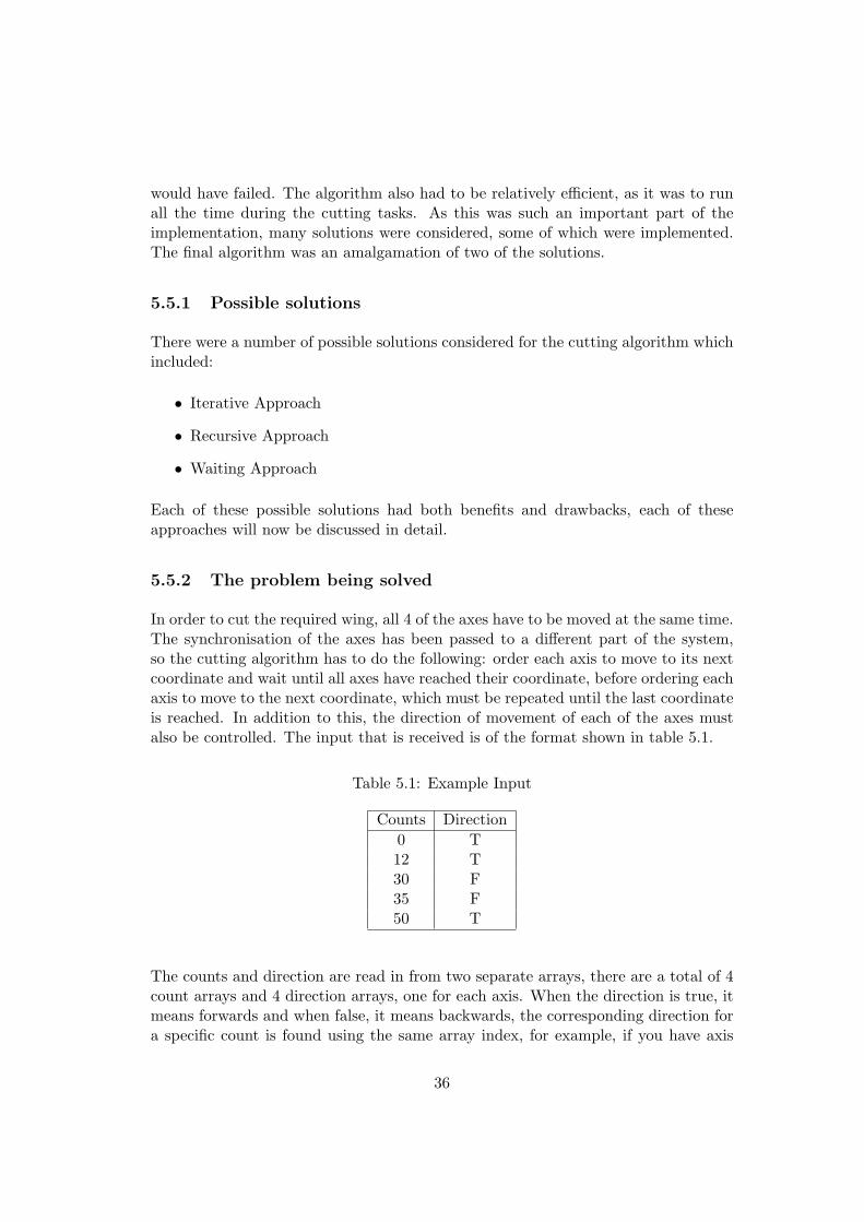
would have failed. The algorithm also had to be relatively efficient, as it was to runall the time during the cutting tasks. As this was such an important part of theimplementation, many solutions were considered, some of which were implemented.The final algorithm was an amalgamation of two of the solutions.
5.5.1 Possible solutions
There were a number of possible solutions considered for the cutting algorithm whichincluded:
• Iterative Approach
• Recursive Approach
• Waiting Approach
Each of these possible solutions had both benefits and drawbacks, each of theseapproaches will now be discussed in detail.
5.5.2 The problem being solved
In order to cut the required wing, all 4 of the axes have to be moved at the same time.The synchronisation of the axes has been passed to a different part of the system,so the cutting algorithm has to do the following: order each axis to move to its nextcoordinate and wait until all axes have reached their coordinate, before ordering eachaxis to move to the next coordinate, which must be repeated until the last coordinateis reached. In addition to this, the direction of movement of each of the axes mustalso be controlled. The input that is received is of the format shown in table 5.1.
Table 5.1: Example Input
Counts Direction0 T12 T30 F35 F50 T
The counts and direction are read in from two separate arrays, there are a total of 4count arrays and 4 direction arrays, one for each axis. When the direction is true, itmeans forwards and when false, it means backwards, the corresponding direction fora specific count is found using the same array index, for example, if you have axis
36
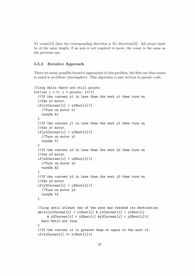
X1 count[12] then the corresponding direction is X1 direction[12]. All arrays mustbe of the same length, if an axis is not required to move, the count is the same asthe previous one.
5.5.3 Iterative Approach
There are many possible iterative approaches to this problem, the first one that comesto mind is as follows (Incomplete). This algorithm is just written in pseudo code.
//Loop while there are still pointsfor(int i = 0; i < points; i++){//If the current x1 is less than the next x1 then turn on//the x1 motor.if(x1Current[i] < x1Next[i]){//Turn on motor x1turnOn X1
}//If the current y1 is less than the next y1 then turn on//the y1 motor.if(y1Current[i] < y1Next[i]){//Turn on motor y1turnOn Y1
}//If the current x2 is less than the next x2 then turn on//the x2 motor.if(x2Current[i] < x2Next[i]){//Turn on motor x2turnOn X2
}//If the current y2 is less than the next y2 then turn on//the y2 motorif(y2Current[i] < y2Next[i]){//Turn on motor y2.turnOn Y2
}
//Loop until atleast one of the axes has reached its destinationwhile(x1Current[i] < x1Next[i] & y1Current[i] < y1Next[i]
& x2Current[i] < x2Next[i] &y2Current[i] < y2Next[i]){Wait Until not true
}//If the current x1 is greater than or equal to the next x1.if(x1Curent[i] => x1Next[i]){
37
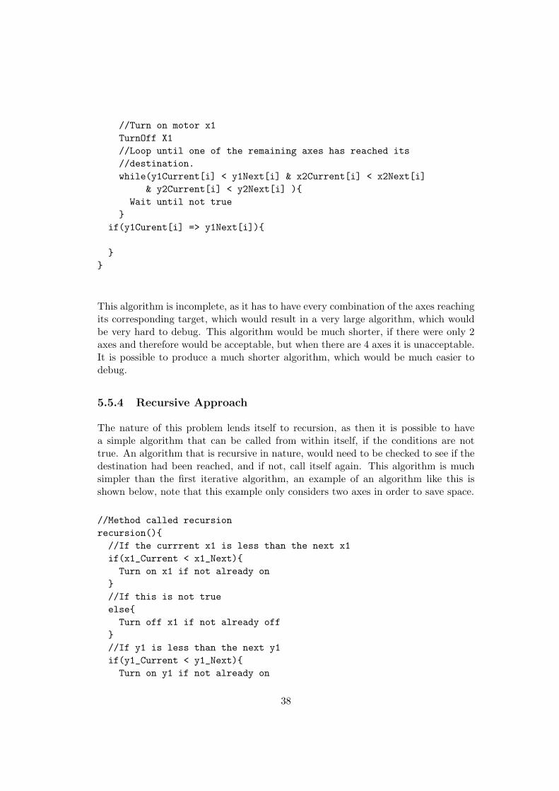
//Turn on motor x1TurnOff X1//Loop until one of the remaining axes has reached its//destination.while(y1Current[i] < y1Next[i] & x2Current[i] < x2Next[i]
& y2Current[i] < y2Next[i] ){Wait until not true
}if(y1Curent[i] => y1Next[i]){
}}
This algorithm is incomplete, as it has to have every combination of the axes reachingits corresponding target, which would result in a very large algorithm, which wouldbe very hard to debug. This algorithm would be much shorter, if there were only 2axes and therefore would be acceptable, but when there are 4 axes it is unacceptable.It is possible to produce a much shorter algorithm, which would be much easier todebug.
5.5.4 Recursive Approach
The nature of this problem lends itself to recursion, as then it is possible to havea simple algorithm that can be called from within itself, if the conditions are nottrue. An algorithm that is recursive in nature, would need to be checked to see if thedestination had been reached, and if not, call itself again. This algorithm is muchsimpler than the first iterative algorithm, an example of an algorithm like this isshown below, note that this example only considers two axes in order to save space.
//Method called recursionrecursion(){//If the currrent x1 is less than the next x1if(x1_Current < x1_Next){Turn on x1 if not already on
}//If this is not trueelse{Turn off x1 if not already off
}//If y1 is less than the next y1if(y1_Current < y1_Next){Turn on y1 if not already on
38
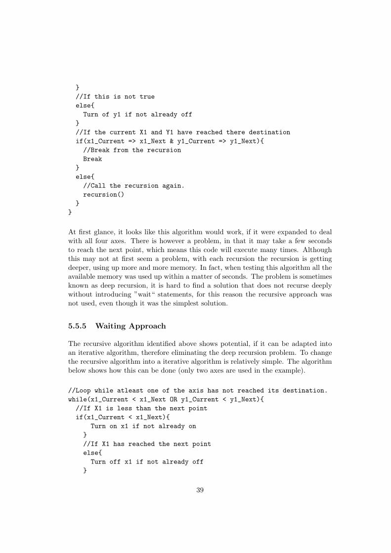
}//If this is not trueelse{Turn of y1 if not already off
}//If the current X1 and Y1 have reached there destinationif(x1_Current => x1_Next & y1_Current => y1_Next){//Break from the recursionBreak
}else{//Call the recursion again.recursion()
}}
At first glance, it looks like this algorithm would work, if it were expanded to dealwith all four axes. There is however a problem, in that it may take a few secondsto reach the next point, which means this code will execute many times. Althoughthis may not at first seem a problem, with each recursion the recursion is gettingdeeper, using up more and more memory. In fact, when testing this algorithm all theavailable memory was used up within a matter of seconds. The problem is sometimesknown as deep recursion, it is hard to find a solution that does not recurse deeplywithout introducing ”wait“ statements, for this reason the recursive approach wasnot used, even though it was the simplest solution.
5.5.5 Waiting Approach
The recursive algorithm identified above shows potential, if it can be adapted intoan iterative algorithm, therefore eliminating the deep recursion problem. To changethe recursive algorithm into a iterative algorithm is relatively simple. The algorithmbelow shows how this can be done (only two axes are used in the example).
//Loop while atleast one of the axis has not reached its destination.while(x1_Current < x1_Next OR y1_Current < y1_Next){//If X1 is less than the next pointif(x1_Current < x1_Next){
Turn on x1 if not already on}//If X1 has reached the next pointelse{Turn off x1 if not already off
}
39
//If Y1 is less than the next pointif(y1_Current < y1_Next){Turn on y1 if not already on
}//If Y1 has reached the next pointelse{Turn of y1 if not already off
}}
As can be seen, this is a very simple modification to the recursive algorithm, it turnsit from an algorithm which will not work in practise, to one which will work. Thisis actually the algorithm that was used in practise, it was chosen as it is relativelysimple and therefore easier to debug than the more complex iterative approach. Thealgorithm used is actually slightly different, as it has a wait statement after eachiteration of the loop, this was included so the loop was not a tight loop, althoughthe loop needs to be running continuously, it is sufficient for it to run every fewmilliseconds, therefore stopping a tight loop which will use all the available processingpower.
5.6 Motor Control
As discussed in the requirements, there was a need to have a simple way to controleach of the motors throughout the program, to make the implementation simpler.A layer of abstraction was needed for both the motor outputs and the inputs. Theparport library was going to be used to control the inputs and outputs, the libraryhas four primary methods.
• read()
• readOneByte(int address)
• write(int oneByte)
• writeOneByte(int address, int oneByte)
The two write methods have no return type (void) and the two read methods returntypes of int.
5.6.1 Motor Output
The output deals with writing data to the parallel port, as the standard data pinsare being used the ”write()“ method can be used. There are 8 data pins, each of
40
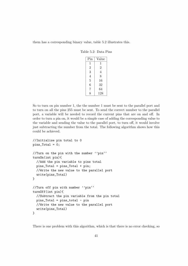
them has a corresponding binary value, table 5.2 illustrates this.
Table 5.2: Data Pins
Pin Value1 12 23 44 85 166 327 648 128
So to turn on pin number 1, the the number 1 must be sent to the parallel port andto turn on all the pins 255 must be sent. To send the correct number to the parallelport, a variable will be needed to record the current pins that are on and off. Inorder to turn a pin on, it would be a simple case of adding the corresponding value tothe variable and sending the value to the parallel port, to turn off, it would involvejust subtracting the number from the total. The following algorithm shows how thiscould be achieved.
//Initialise pin total to 0pins_Total = 0;
//Turn on the pin with the number ’’pin‘‘turnOn(int pin){//Add the pin variable to pins totalpins_Total = pins_Total + pin;//Write the new value to the parallel portwrite(pins_Total)
}
//Turn off pin with number ’’pin‘‘turnOff(int pin){//Subtract the pin variable from the pin totalpins_Total = pins_total - pin//Write the new value to the parallel portwrite(pins_Total)
}
There is one problem with this algorithm, which is that there is no error checking, so
41
it is possible to turn off pins that are not on, aswell turn pins on that are already on.This poses a major problem, as incorrect values could be sent to the parallel port.There are two solutions to this, having the error checking in this section of code, orhaving it in the section where there is a named method to turn on each motor (motorcontroller). As this code will always be accessed through the motor controller, thereis no need to have the error checking in this section of the code.
5.6.2 Motor Controller
In order to make the control of the motors easy throughout the rest of the program, itis necessary to have methods such as ”turn On X1()“. As there is no error checkingin the motor control code, it was necessary to have code to check which motors areon/off, before the results are sent to the parallel port. In order to do this, it wasnecessary to have two booleans for each of the motors, one for the on/off status andone for the direction. The convention that was chosen, was for the on/off status trueto mean on and for the direction true to mean forwards. It was also necessary to storethe pins that each motor uses to achieve their functions. The following algorithmshows how the motor control can be achieved for one axis.
//Import the pinlayoutimport pinlayoutboolean x1_On, x1_Dir
//Used to turn on X1x1_On(){//If X1 is not already onif(x1_On == false){//Send the number representing X1 to the motor output//to turn on motor X1turnOn(x1_On)
}}
//Used to turn off X1x1_Off(){//If X1 is turned on alreadyif(x1_On == true){//Turns off motor X1turnOff(x1_On)
}}
//Used to set the direction of X1 to forward
42
x1_Forward(){//If X1 is currently set to backwardsif(x1_Dir == false){//Set X1 to forwardturnOff(x1_Back)
}}
//Used to set the direction of X1 to reversex1_Backwards(){//If X1 is currently set to forwardsif(x1_Dir == true){//Set X1 to backwardsturnOn(x1_Back)
}}
This is actually a simplified version of the algorithm that was used, as it onlydeals with axis x1. The actual algorithm is more complex, as it has variables foron,off,forwards and backwards, for each axis. This is an extra level of error checking,so that it takes more than one boolean to be set to the incorrect value, for the outputto the parallel port to be set incorrectly. The pinlayout is imported from a variablesinterface, which means it would be possible to change the pins that are used for eachof the axis. If the variables interface is changed, this adds an extra level of flexibil-ity which would not be available, if the pins used were hard coded into the controlalgorithm. The full solutions to both the motor control and data pins can be foundin the code listings.
5.7 Motor Inputs
The Motor outputs are controlled by the user and they occur when requested, this ishowever not the case with the motor inputs, which are indirectly caused by turningon an axis, but they do need to be monitored all the time, in order not to miss anyinputs. It is also very important not to miss any of the inputs, or else the accuracywill be dramatically reduced. It is vital not to sense more inputs than actually occur,as this too would result in less accuracy. To achieve this, a part of the programneeded to be running all the time, listening for inputs. This part of the programrequired a higher priority than the rest, to achieve this, the thread priority of theinput listener needed to be higher than the rest of the program. There was howeveran inherent problem with this, if the input listener had too high a priority, the restof the program would not get a chance to run, meaning therefore that the programwould not achieve its goal.
43
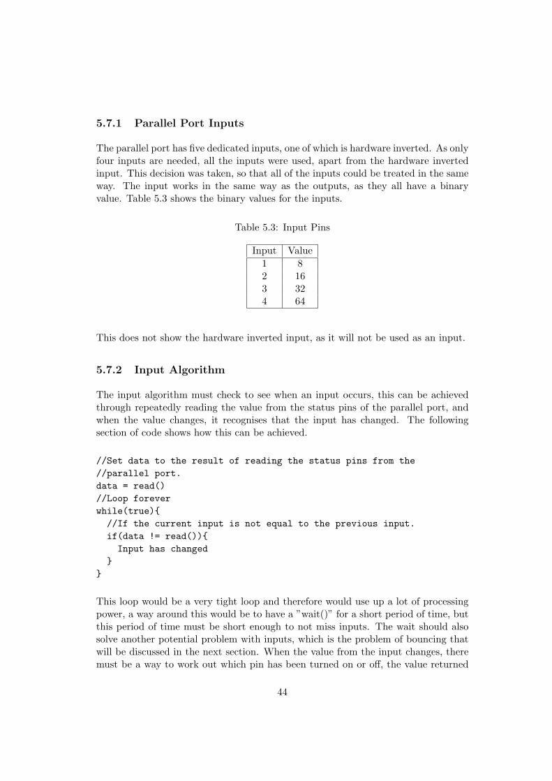
5.7.1 Parallel Port Inputs
The parallel port has five dedicated inputs, one of which is hardware inverted. As onlyfour inputs are needed, all the inputs were used, apart from the hardware invertedinput. This decision was taken, so that all of the inputs could be treated in the sameway. The input works in the same way as the outputs, as they all have a binaryvalue. Table 5.3 shows the binary values for the inputs.
Table 5.3: Input Pins
Input Value1 82 163 324 64
This does not show the hardware inverted input, as it will not be used as an input.
5.7.2 Input Algorithm
The input algorithm must check to see when an input occurs, this can be achievedthrough repeatedly reading the value from the status pins of the parallel port, andwhen the value changes, it recognises that the input has changed. The followingsection of code shows how this can be achieved.
//Set data to the result of reading the status pins from the//parallel port.data = read()//Loop foreverwhile(true){//If the current input is not equal to the previous input.if(data != read()){Input has changed
}}
This loop would be a very tight loop and therefore would use up a lot of processingpower, a way around this would be to have a ”wait()” for a short period of time, butthis period of time must be short enough to not miss inputs. The wait should alsosolve another potential problem with inputs, which is the problem of bouncing thatwill be discussed in the next section. When the value from the input changes, theremust be a way to work out which pin has been turned on or off, the value returned
44
by “read()“ is an integer, from this integer an algorithm is needed to decide whichpin has been turned on. The following algorithm was used to do this.
//If the data variable minus the value of x1 status if greater than 0if(data - x1_Status => 0){X1 must be on//Subtract the value of x1 status from the data variabledata = data - x1_Statusx1_On = true
}//X1 input is not onelse{//Set x1 status to offx1_On = false
}//If the data variable minus the value of y1 status is greater than 0if(data - y1_Status => 0){Y1 Must be on//Subtract the value of y1 from the data varaibledata = data - y1_Statusy1_Status = true
}//Y1 inout is not onelse{//Set y1 status to offy1_Status = false
}
This algorithm does however have a problem, which is that the if statements mustbe in order from largest input pin value to smallest, or else the incorrect status willbe found. This does not seem like a problem, but it does means that the order of theinput pins are fixed and cannot easily be changed, without necessitating changingthe order of the ”if statements“. There was no easy way to solve this problem, so theorder of the inputs has been fixed and cannot be changed.
The input that the cutting algorithm is given consists of an accumulative set ofcounts, which means that the input algorithm needs to store the total number ofcounts for the axes, these counts must be available from the cutting algorithm. Inorder to do this, there must be a count variable that can be accessed from the cuttingalgorithm, this variable must be incremented every time an input for the axis occurs.The following section of code shows how this was achieved.
//If the current status of X1 is not equal to the old status.
45
if(x1_Status != x1_Status_Old){//Increment the x1 counter by one.x1_Count ++
}
As can be seen the status of the axis must be stored in a variable before the checkoccurs, so that it is possible to tell which of the axes has had a count. The countoccurs when an input changes state, from on to off, or from off to on. The algorithmshown is a shortened version of the actual algorithm, which can be found in the codelistings.
5.8 Xfoil Integration
The integration with Xfoil was needed to ensure that the aerofoils were of a highenough resolution to cut smooth aerofoils of differing sizes. The aerofoils read fromthe aerofoil database had a limited number of coordinates, so this needed to beincreased. The method identified in the literature survey was the use of XFoil (anaerofoil manipulation program). The implementation posed some problems, as Xfoilis available for both Windows and Linux, but is run from the command line, thereforethe commands needed to execute it were different in Windows to Linux. This meantthat two sets of commands were needed to integrate Xfoil into the program. The otherproblem, was that the format of the output files differ in the Windows and Linuxversions. The final issue uncovered, was that Xfoil can only generate a maximumof 354 coordinates in Linux and even less in Windows. This proved to be a majorproblem, as a large aerofoil requires more than 354 coordinates if it is to be of sufficientresolution to produce a smooth aerofoil. Solutions to these problems were found andwill be discussed in this section.
5.8.1 Operating System Dependence
As Xfoil is run from the command line, and different commands are needed in bothLinux and Windows, the first task, in order to run it, was to identify the operat-ing system being used. This was a simple case of using the in-built method Sys-tem.getProperty(”os.name”), the result of this command decides which code shouldbe executed, this was achieved through a simple set of if statements. It was decidedthat a set of ”.bat“ scripts for Windows and ”.sh“ for Linux would be used to executeXfoil. An example of one of these scripts,a Linux script, is shown below.
//Change dirctory to xfoilcd xfoil//Run xfoil./xfoil <"script_0.xfc"> Xfoil.out
46
As can be seen, Xfoil is executed with the arguments 〈”script 0.xfc”〉 and Xfoil.out,the latter is an output for what would have happened on the command line ifit had been run interactively, it was included for debug purposes. The former〈”script 0.xfc”〉 is the set of commands that XFoil is to execute when it is run, theseare platform independent. An example of one of these inputs is shown below.
LOAD 0old.datpparn250
save 0new.datQUIT
These commands are identical to the commands that would be issued at the commandline if Xfoil were to be run interactively, the two newlines indicate carriage returns.There are 10 of the ”.bat“ or ”.sh“ files, depending on the operating system, and10 Xfoil inputs, which allows for up to 2500 coordinates. This has covered all theoperating system dependencies.
5.8.2 Getting ready to run Xfoil
As can be seen from the commands that are executed, the aerofoils always have thesame name, this is so that there is no need for new input files for Xfoil for everyaerofoil. Xfoil is contained in its own directory ”xfoil“, in order to run xfoil with therelevant aerofoil, the aerofoil must be copied from the ”aerofoils“ directory to the”xfoil“ directory, this is done using a simple piece of code. The piece of code takestwo arguments, the aerofoil name and the directory it is in, and the directory it isto be copied to, which is hard coded to ”xfoil“ . The initial aerofoil is given to Xfoilto generate 250 coordinates, the result from this is used to generate the number ofcoordinates required.
5.8.3 Number of coordinates required
The number of coordinates required depends on the chord length of the wing, theincrements per rotation and the pitch of the threaded rod. Long wings will requiremore coordinates than shorter wings in order to be of equal smoothness. The problemthat arises here, is that the Y axis will require less coordinates than the X axis. Itwould have been unwise to give the Y axis more coordinates than required, as thecutter would then have been unable to move the Y axis the small amounts needed.Instead of doing this, a solution was devised where the approximate optimal number
47
of Y coordinates was calculated and the same number of X coordinates generated.To do this the lengths and heights of a few common aerofoils were measured to finda ratio between height and length, as a result a ratio of 7 to 1 was identified as beingadequate.
The first step in working out the number of required coordinates was to work outthe ideal number the X axis would have. This was done using equation 5.1.
coordinates = (length/pitch) ∗ increments (5.1)
The ratio of X to Y has been set at 7 to 1, therefore the number of points will bedivided by 7 to get the number of points that will actually be needed. Now that thenumber of coordinates actually needed have been identified, a method of generatingthe coordinates was needed.
5.8.4 Coordinate generation
As Xfoil can only generate 354 coordinates at a time, a method to generate morewas required. The method devised was to get Xfoil to generate multiple sets ofcoordinates per aerofoil, the inputs for xfoil had been set at 250 coordinates each,but there was a problem in that the ideal number was unlikely to be a multiple of250. In order to get around this problem it was necessary to work out the numberof multiples of 250 needed, the number required is rounded up to the nearest 250.Equation 5.2 shows the formula used.
multiples = d(coordinates÷ 7)÷ 250e (5.2)
The number of multiples was capped at 10, this was done so that the number of inputfiles needed for xfoil was not infinite. A method where there was no cap was tried,but this did not work, due to a problem with the buffer writer.
To create this number of multiples it was necessary to split the original aerofoilinto an equal number of segments, and then write each of these to a ”.dat“ file, whichwas achieved using a simple Print Stream built into Java. Each of these outputfiles are named i+old.dat where i is the number of the input file from 0 to 9. Eachof these input files are then sent to Xfoil for the relevant number of coordinatesto be generated. These are sent one after another, and result in the correspondingnumber of new ”.dat“ files, these are named ”i+new.dat” where i is the same aspreviously stated. The cutting algorithm needs one aerofoil to be sent to it, notmultiple segments, which meant that the new aerofoils needed to be reconstructedinto a single aerofoil.
48
5.8.5 Aerofoil Reconstruction
To reconstruct the aerofoil, each of the parts needed to be read back in and combinedto make one new aerofoil. This was done using the aerofoil input reader multiple timesfor each of the aerofoils and then combining them into one large array. There is noneed to save the resulting aerofoil back to a “.dat” file, as the coordinates can begiven straight to the cutting algorithm.
5.9 Synchronisation
Synchronisation was one of the most difficult problems encountered when writingthe program. The two kinds of synchronisation required, as illustrated in the liter-ature survey were length based and surface based, but each of these posed differentproblems. The solution to the problems have been discussed in greater detail in theliterature survey. Reasearch did not provide a satisfactory solution necessitating anoriginal solution to be devised. The length based synchronisation was simpler as allthat needed to be done was generate points at set intervals. The spacing of theseintervals was calculated using 5.3.
interval = 1÷ (points÷ 2) (5.3)
Once the interval had been generated, it was a case of starting from the back ofthe aerofoil, collecting points at the interval calculated. In order for this to worksuccessfully, the input aerofoil needs to be of a much higher resolution than theaerofoil to be generated. An enhancement to this algorithm would be to have analgorithm that interpolated the points required from the available points, allowing alower resolution aerofoil to be used.
The surface based synchronisation required a more sophisticated approach. The ideabehind surface based synchronisation is that the points will be spread at equal inter-vals over the surface of the aerofoil. The first step in achieving this was to calculatethe perimeter of the aerofoil. This was achieved using the following algorithm.
//Loop until all the coordinates have been usedfor(int i = 1; i < length;i++){
//Set tmp_x to the previous array index contents minus the//current array index contentstmp_x = X[i-1]-X[i];//Square the variable tmp_x and store in tmp_xtmp_x = tmp_x^2;//Set tmp_y to the previous array index contents minus the//current array index contents
49
tmp_y = Y[i-1]-Y[i];//Square the variable tmp_ytmp_y= tmp_y^2;//Set the perimeter to the old perimeter plus the square root of//tmp_x plus tmp_yperimeter = perimeter + (tmp_x+tmp_y)^1/2;
}
This algorithm calculates the perimeter of the aerofoil, this perimeter can then bedivided by the number of points needed. In order to calculate the points needed thefollowing algorithm is used.
//Set perimeter to 0perimeter = 0;//Loop until enough points have been generatedfor (int j = 1; j<points_Needed;j++){//Add the point interval to the perimeterperimeter = perimeter + intervale;//Set the first variable to falseboolean first = false;//Set the perim_Pos variable to 0perim_Pos = 0;//Loop until all the points have been checkedfor (int k = 1; k < aerofoil_Length; k++){//Set tmp_x to the previous array index contents minus the//current array index contentstmp_x = X[i-1]-X[i];//Square the variable tmp_x and store in tmp_xtmp_x = tmp_x^2;//Set tmp_y to the previous array index contents minus the//current array index contentstmp_y = Y[i-1]-Y[i];//Square the variable tmp_ytmp_y= tmp_y^2;
//Set the perim_Pos to the old perim_Pos plus the square//root of tmp_x plus tmp_yperim_Pos = perim_Pos + (tmp_x+tmp_y)^1/2;
//If the perimeter is less than the perim_Pos variable and//first equals false
50
if(perimeter < perim_Pos && first == false){//Set to true.first = true;//Set array x_New index j to the current x point being//consideredx_New[j]=X[k];//Set array y_New index j to the current y point being//consideredy_New[j]=Y[k];
}}
}
This generates both the X and Y coordinates required. Like the length based algo-rithm, this algorithm also requires an aerofoil of a much higher resolution than theoutput aerofoil.
Once the set of points has been generated, the generated points are written to a “.dat”file and copied into the aerofoil database so that they can be used when required.
5.10 GUI
The GUI was generated using Netbeans, which will not be discussed in detail, theonly part of the GUI that warranted discussion was the tapered wing calculationwhich is built into the GUI.
51
Chapter 6
System Testing
Testing of the system was carried out through the development of the system, thiswas done as individual pieces of the system were reliant on other pieces. The testingof individual pieces of the system were carried out using print statements in the code,once the piece of the system was working correctly the print statements were removed.However once the system was finished, more detailed testing was required, to checkthat the system worked correctly and the required functionality was provided. Thenames for the two forms of testing used are commonly known as:
Validation: the process of checking the product meets the requirements set out.
Defect Testing: the aim to find defects in the software system.
The validation was carried out by checking that each of the requirments in therequirement specification hax been furfilled. The defect testing was carried out bytesting each section of code with normal, extreme and erroneous values, this was doneto find out how the code behaved in different circumstances.
6.1 Hardware Used
The developed system was to work on both Linux and Windows, which requiredtesting with both operating systems. The testing was planned to be conducted ontwo different machines, one for Windows and one for Linux. The Windows machinewas a Hewlett Packard laptop and the Linux machine was a Desktop PC, both ofthese computers were tested prior to the testing, to ensure the parallel ports workedas expected. An additional spare laptop was made available, in case either of themachines failed, this machine had no operating system installed so that it could beused as a backup for either of the machines. Just before testing started the HewlettPackard laptop failed, this should not have posed a problem as the back up laptop wasavailable. Once Windows was installed and configured, the testing could commence
52
on Windows. There was a problem with the testing carried out on the laptop, taskssuch as manual motor control that did not require the use of the inputs workedcorrectly, but any task that required the use of inputs did not work. After muchinvestigation it was found that the hardware inverted pin of the parallel port wasnot actually hardware inverted, this meant that the pin was always in the incorrectstate. As the hardware inverted pin has the value of 128, which is higher than all theother inputs, this meant that the other inputs were not sensed, due to the total beinghigher that expected. The fact that the backup laptop did not work as expectedwas a problem, as at the time of testing there was no other machine available with aparallel port. A solution to the problem was found, this solution involved installingWindows on the desktop after the testing under Linux had been completed. Due tothe time that was taken up setting up both the spare laptop and the desktop, therewas not time to carry out thorough testing in Windows, instead just a few tests wereimplemented.
Although only a few tests were carried out under Windows, the testing should besufficient, as the JAVA platform means that if the solution works under Linux itshould also work under Windows, due to the platform independent nature of JAVA.As limited testing has been carried out and shown to work correctly, the testingconducted under Linux should also be valid under Windows.
6.2 Validation Testing
The validation testing was conducted under Linux, with the exception of the testchecking the system would operate under Windows. The test plan and results areshown in Appendix B. The tests that require additional explanation are highlightedin this section.
The non functional hardware test number 3 specified that the software should beable to use a counter on each axes. This test was successful, as a counter can be usedon each axis, however the software will not work if a counter is not present. Thedecision to make it mandatory to have a counter on each axis was chosen, as the levelof accuracy would have been very poor without a counter on each axis.
The functional test, testing if a spar slot can be cut in the same pass as a wing,produced a Fail result. This requirement had the priority of “may” which means thefact that the test failed is not critical. This functionality would have been prefer-able, but not critical. As this requirement is not critical, no additional work will becarried out to rectify the failing of the test. The reason this test failed, was that thefunctionality was not implemented, due to the problems that were associated withthe it.
53
6.3 Defect Testing
The defect testing was carried out in a black box way. According to [31] blackbox testing is “ testing without knowledge of the internal workings of the item beingtested.” The black box method was chosen, as it is more likely to find faults which willoccur in normal usage, than a white box testing strategy, which is conducted withknowledge of how the system works internally. The defect testing was conductedexclusively under Linux. The test plan is included in Appendix B. The areas oftesting that require additional explanation have been highlighted in this section.
Test number 1 highlighted a problem with the block cutting procedure, it allowedletters of the alphabet to be entered into the length fields, resulting in an exception.Although this input is not expected, it is unacceptable for an exception to occur ifa user enters invalid information. Therefore this issue needed addressing, this issuewas not a just an issue for block cutting, it was present throughout the system.Before any more testing was conducted these issues were resolved. These issueswere resolved through only allowing numbers to be entered into the fields, if a nonnumber is entered, the value is discarded and a blank field is displayed. Once thishas been fixed, the test was carried out again, to check the modification had solvedthe problem.
6.4 User Testing
The user testing did not play a large role in the testing of the program, however therewas one test which required the user to use the software. The user was not requiredto cut a wing, due to the hardware not being available, but they were required toset up the software, ready to cut a wing. The user testing showed that the softwareis simple enough to use with minimal tuition, however the software is not designedto be used by a novice user and for this reason a user with an appropriate level ofknowledge was chosen.
6.5 Conclusion
The testing strategy chosen has proved to be successful, some of the tests failed atfirst, but once the code had been modified, the tests were successful. There wereonly a limited number of tests carried out, this was due to the limited time thatwas available. However testing was carried out throughout the development of thesoftware, this testing proved to be very beneficial, as less bugs were highlighted duringthat actual testing.
54
Chapter 7
Conclusion
The main objective of this project was to design and implement software for a CNCpolystyrene cutter, which only used simple external hardware, therefore reducing thefinantial outlay required to produce model aircraft wings. This main objective hasbeen met. The majority of the requirements highlighted in the requirements chapterhave also been met. There were however just a few requirments that have not beenmet, the reasons why they were not met are different and will be highlighted in theevaluation.
Another of the aims of the project, was to reduce the cost that was associatedwith CNC polystyrene cutting. This was to be achieved through the elimination ofthe expensive stepper motors and associated control circuitary replacing them withDC motors and simple external circuitary. The project has been successful in thisarea, as the external hardware that was used is relatively simple, as illustrated inAppendix A and the required components can be purchased relatively cheaply. Themotors used to control the axes are simple DC motors, electric screwdrivers wereused in the example. If this software were to be used, the associated cost wouldbe substantially less than that of existing producs, however all the hardware wouldhave to be assembled by the end user, as there are no ready to use versions of theelectronics available. In order to build the hardware the user would need to havebasic soldering skills in order to assemble the electronics. Alternatively a “BreadBoard” could be used, if the user had no soldering experience, but this would makethe electronics fragile. If the cost of the hardware were to be kept down, it would alsohave to be built by the end user. Commercially available hardware solutions couldhowever be used with a minimal amount of adaption, but would incur a substantialfinancial outlay.
55
7.1 Project Evaluation
Although the main objective of the project has been met, there were many areas ofthe project that posed difficulties during the development and testing of the software.The testing of the product turned out to be particularly difficult, due to the failureof one of the test computers. Although alternative arrangements had been made, inorder to guard against failure of test machines, this did not prove to be sufficient. Aspare machine was made available, but it would have been more beneficial to havetested the machine to ensure that it worked as expected, before relying on it in thecase of failure. The learning outcome of this, was that not all parallel ports work thesame, and some do not seem to comply to expected standards.
Problems were also encountered during the implementation phase, but most ofthese problems were resolved after formulating alternative solutions to the problems.There was however, one requirement that posed more problems that the rest, thiswas the requirement for cutting spars in the same pass. The main reason this posedsuch a problem, was due to the way the wing cutting algorithm had been designed.As a result there was a major decision that had to be made, either to redesign thecutting algorithm or ommit the ability to cut spar slots in the same pass. The cuttingalgorithm had been designed in such a way to simplify the rest of the implementation,and for this reason the cutting algorithm was left untouched but the ability to cutspars in the same pass was sacrificed to some extent. A solution was posed, wherethe user would generate an aerofoil with the spar slot built in, which meant therewas still a possibility to cut spars in the same pass but substantial work on behalf ofthe end user would be required to achieve this.
The planning for the project proved to be adequate, however the time allocatedfor tasks was too short, which meant that the project started to get behind schedule.This would have posed a major problem if this had not been planned for, additionaltime had been allowed at the end of the project for catch up. This meant that theproject was completed on time, however it did mean that there was less time fordrafts of the dissertation.
7.2 If the project was to run again
If this project were to run again, there would be some things that would be donedifferently. The main area that would be changed, would be the time allowed fortasks, this would have been achieved through planning to complete more tasks before
56
the Christmas break. In addition to this, more effort would have been made to writesections of the project as the project progressed, which would have left less writingto be completed at the end.
7.3 Further Work
There are many areas of the developed solution that would benefit from extension.Some of these areas were not considered in the requirements, as they were consideredto be too complex and their inclusion might have meant that the project would nothave been completed.
7.3.1 Configurable Inputs and Outputs
Currently the inputs and outputs that must be used are hard coded into the solution,this does not allow for any flexibility in the way that the hardware must be connectedto the computer. It would not require much modification to change the outputs thatare used for each axis, although the use of different inputs would require the inputalgorithm to be rewritten from the ground up. If this were to be done an interfacewould be required allowing the user to specify which inputs and outputs belong towhich axis. This would be a useful modification, however the effort required to allowfor the inputs to be changed would be great.
7.3.2 Synchronisation Extension
Currently the solution offers the ability to produce length and surface synchronisedaerofoils, however there is no interpolation of the points, the nearest point to therequired point is used. An improvement to this would be to have interpolation sothat a lower resolution aerofoil could be used to produce synchronised aerofoils. Itwould additionally be useful to be able to produce synchronised versions of aerofoils,without needing to use a different interface and generate a new .dat file for eachsynchronised aerofoil that is required. The method of interpolation used could be asimple linear interpolation, or a spline interpolation could be used to achieve a higherlevel of accuracy.
7.3.3 Common Tasks
If this piece of software was to be used in practise, it is likely that the user wouldcut the same wing a number of times, especially if the software was used by a modelaircraft kit manufacturer. Currently, if the same wing is required multiple times, itmust be newly input each time, this is both time consuming and prone to error. Abetter solution to this problem would be the ability to save common wings that are
57

cut and have a method to select a preset wing, without having to reinput all therequired data.
58
Bibliography
[1] Fcut. URL http://www.homecnc.org/index.php/FCut (Nov 2006).
[2] Roger S. Pressman and John E. Williams. Numerical Control and Computer-Aided Manufacturing. John Wiley & Sons, 1977. ISBN 0-471-01555-5.
[3] P Krishnamurthy and F Khorrami. On intriguing effects of closed-loop commu-nication delay in stepper motor control with application of parameter estimation.Proceedings of the 2006 American Control Conference, pages 3170–3176, June2006.
[4] Marc Bodson, Jeffrey S. Sato, and Stephen R. Sliver. Spontaneous speed rever-sals in stepper motors. IEE transactions ems technologyon control syst, 14(2):369–373, March 2006.
[5] Mike J Johnson and Guru Subramanyam. A parallel port interface circuit forcomputer control applications involving multiple stepper motors. Circuits andSystems, 1996., IEEE 39th Midwest symposium on, 2:889–892, August 1996.
[6] Stepper motor and servo motor advisory and applications, . URLhttp://www.netmotion.com/htm files/adv motors.htm.
[7] Gmfc. URL http://gm.cnc.free.fr/en/index.html (Nov 2006).
[8] Jedicut. URL http://www.aeropassion.net/ (Nov 2006).
[9] Googletranslator. URL http://www.google.com/translate.
[10] Mono project. URL http://www.mono-project.com/.
[11] hobbycnc. URL http://www.hobbycnc.com/.
[12] Mark Drela. Xfoil. URL http://web.mit.edu/drela/Public/web/xfoil/.
[13] Profili. URL http://www.profili2.com/.
[14] Mark Barton, Shamim Mohamed, Lloyd MacLean’s, andElodie Roux. University of illinois aerofoils. URLhttp://www.ae.uiuc.edu/m-selig/ads/coorddatabase.html.
59
[15] David Clark. Toward a new generation of simpler pcs. Computer, 32(12):17–19,December 1999. ISSN 0018-9162.
[16] Legacy vs. legacy-free interfaces. Website article, December 2001. URLhttp://www.microsoft.com/whdc/archive/Lfinterface.mspx (Nov 2006).
[17] Tomas Franzon. UserPort Documentation, May 2001.URL http://www.embeddedtronics.com/public/Electronics/minidaq/userport/UserPort.zip.
[18] Gary S. Robinson and Carl Cargill. History and impact of computer standards.Computer, 29(10):79–85, October 1996.
[19] Introduction to serial communications, . URLhttp://www.taltech.com/TALtech web/resources/intro-sc.html (Nov2006).
[20] M. Popa, M. Marcu, and A. S. Popa. A microcontroller based data acqusitionsystem with usb wnterface. Electrical, Electronic and Computer Engineering,2004. ICEEC ’04. 2004 International Conference on, pages 206– 209, September2004.
[21] Robert D Lorenz and Peter B Schmidt. Synchronized motion control for processautomation. Industry Applications Society Annual Meeting, 1989., ConferenceRecord of the 1989 IEEE, 2:1693–1698, October 1989.
[22] Judith Bishop and Basil Worral. Towards platform independence: regarding guilibraries on .net. Proc. 3rd Conf .NET Technologies, pages 23–33, May 2005.
[23] Gongzhu HU and Avinashkumar Gadapa. Compiling c++ programs to javabytecode. Software Engineering, Artificial Intelligence, Networking and Par-allel/Distributed Computing, 2005 and First ACIS International Workshop onSelf-Assembling Wireless Networks. SNPD/SAWN 2005. Sixth InternationalConference on, pages 56– 61, May 2005.
[24] Juan Gabriel Del Cid. Parallel printer port access through java. URLhttp://www.geocities.com/Juanga69/parport/index.html.
[25] Rcgroups foam cutting software comparison. URLhttp://www.rcgroups.com/forums/showthread.php?t=469391 (Jan 07).
[26] Ian Sommerville. Software Engineering 7. Pearson Education Limited, 7 edition,2004. ISBN 0-321-21026-3.
[27] Sun parallel port. URL http://java.sun.com/products/javacomm/ (March2007).
[28] Java os name. URL http://java.sun.com/j2se/1.5.0/docs/api/java/lang/System.html(March 2007).
60

[29] Netbeans ide. URL http://www.netbeans.org/.
[30] Kate text editor. URL http://kate-editor.org/.
[31] Thomas Raishe. Black box testing. URLhttp://www.cse.fau.edu/ maria/COURSES/CEN4010-SE/C13/black.html.
[32] Parallel port pin layout. URL http://www.lammertbies.nl/comm/cable/parallel.html.
61
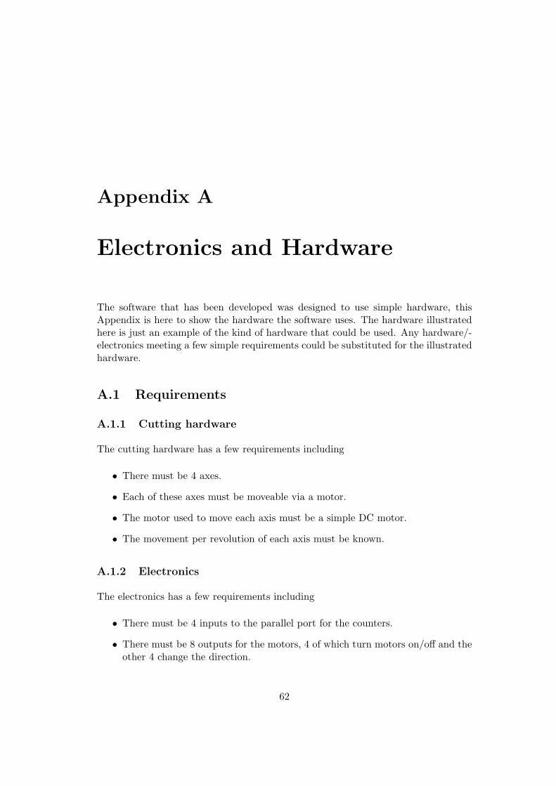
Appendix A
Electronics and Hardware
The software that has been developed was designed to use simple hardware, thisAppendix is here to show the hardware the software uses. The hardware illustratedhere is just an example of the kind of hardware that could be used. Any hardware/-electronics meeting a few simple requirements could be substituted for the illustratedhardware.
A.1 Requirements
A.1.1 Cutting hardware
The cutting hardware has a few requirements including
• There must be 4 axes.
• Each of these axes must be moveable via a motor.
• The motor used to move each axis must be a simple DC motor.
• The movement per revolution of each axis must be known.
A.1.2 Electronics
The electronics has a few requirements including
• There must be 4 inputs to the parallel port for the counters.
• There must be 8 outputs for the motors, 4 of which turn motors on/off and theother 4 change the direction.
62
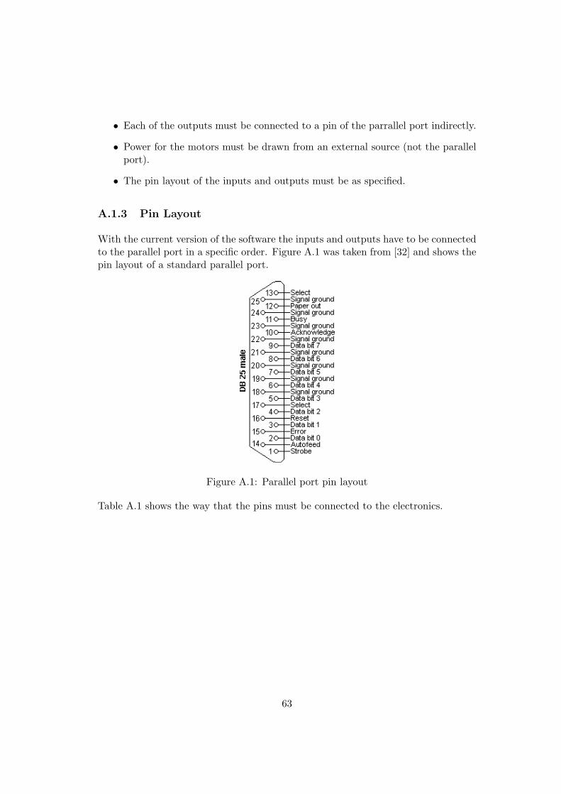
• Each of the outputs must be connected to a pin of the parrallel port indirectly.
• Power for the motors must be drawn from an external source (not the parallelport).
• The pin layout of the inputs and outputs must be as specified.
A.1.3 Pin Layout
With the current version of the software the inputs and outputs have to be connectedto the parallel port in a specific order. Figure A.1 was taken from [32] and shows thepin layout of a standard parallel port.
Figure A.1: Parallel port pin layout
Table A.1 shows the way that the pins must be connected to the electronics.
63
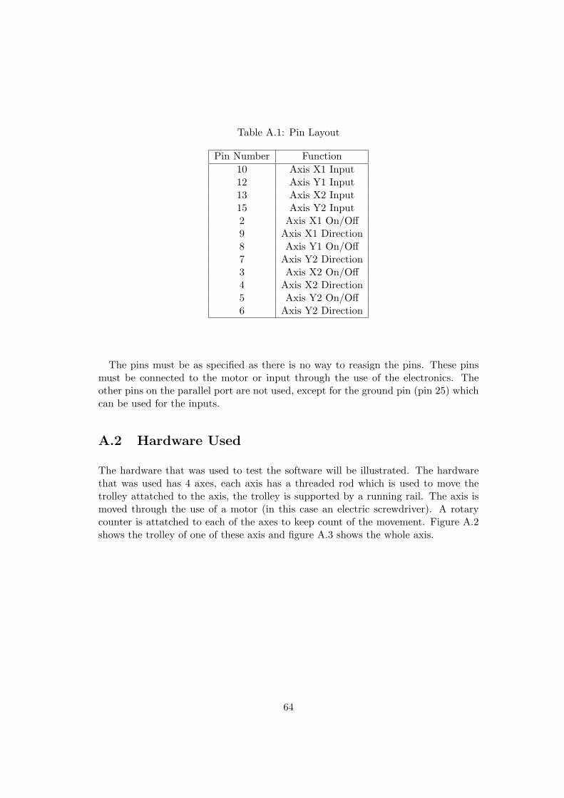
Table A.1: Pin Layout
Pin Number Function10 Axis X1 Input12 Axis Y1 Input13 Axis X2 Input15 Axis Y2 Input2 Axis X1 On/Off9 Axis X1 Direction8 Axis Y1 On/Off7 Axis Y2 Direction3 Axis X2 On/Off4 Axis X2 Direction5 Axis Y2 On/Off6 Axis Y2 Direction
The pins must be as specified as there is no way to reasign the pins. These pinsmust be connected to the motor or input through the use of the electronics. Theother pins on the parallel port are not used, except for the ground pin (pin 25) whichcan be used for the inputs.
A.2 Hardware Used
The hardware that was used to test the software will be illustrated. The hardwarethat was used has 4 axes, each axis has a threaded rod which is used to move thetrolley attatched to the axis, the trolley is supported by a running rail. The axis ismoved through the use of a motor (in this case an electric screwdriver). A rotarycounter is attatched to each of the axes to keep count of the movement. Figure A.2shows the trolley of one of these axis and figure A.3 shows the whole axis.
64
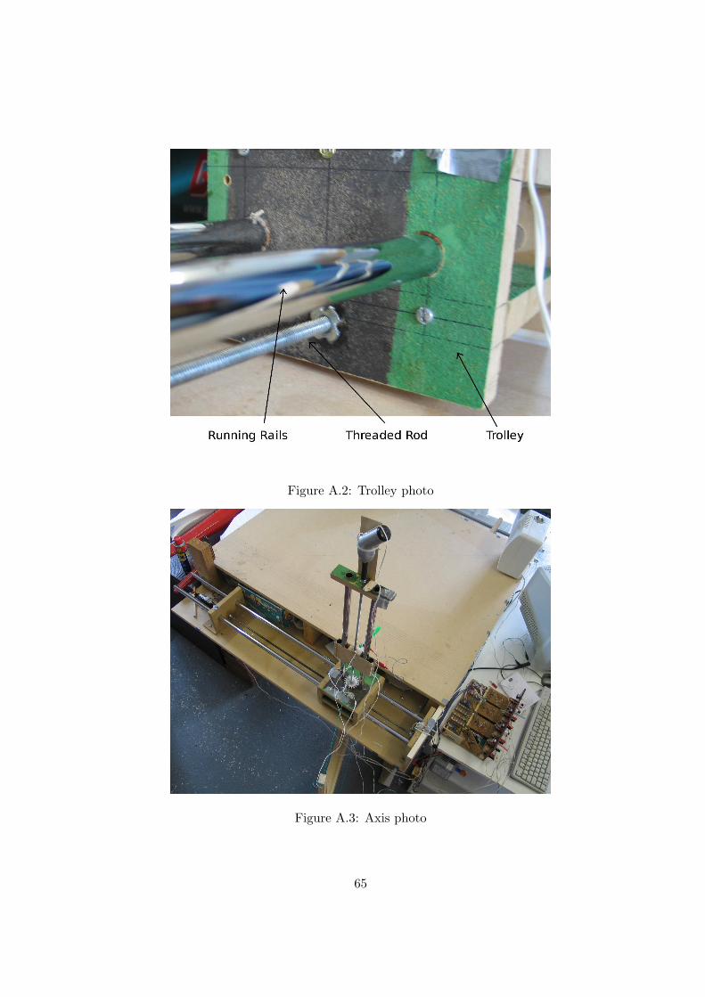
Figure A.2: Trolley photo
Figure A.3: Axis photo
65
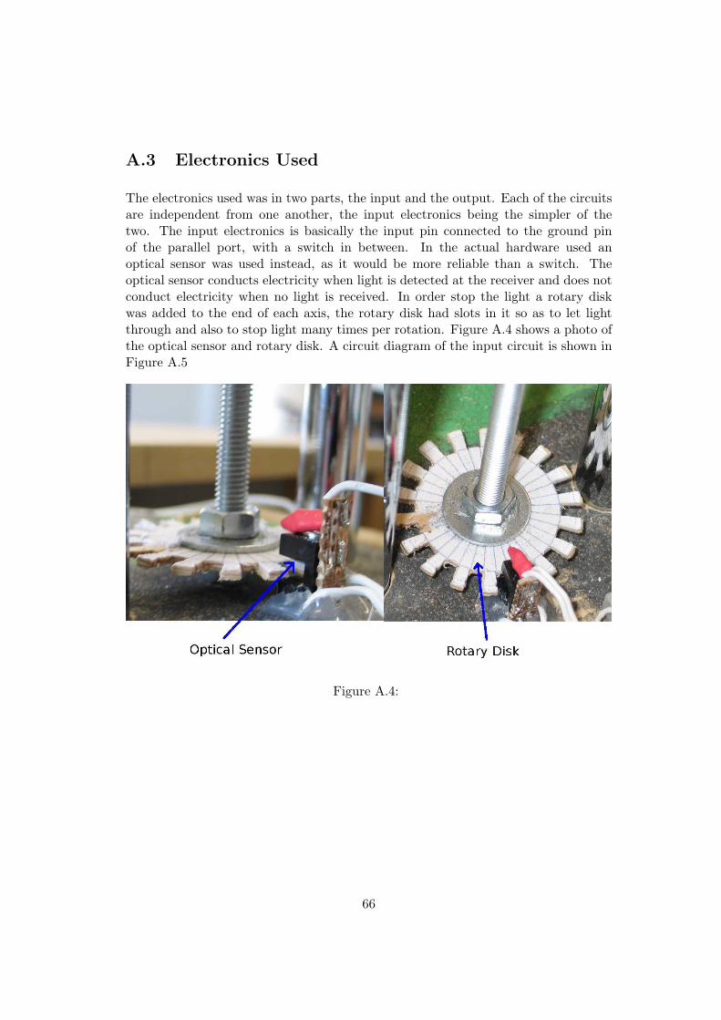
A.3 Electronics Used
The electronics used was in two parts, the input and the output. Each of the circuitsare independent from one another, the input electronics being the simpler of thetwo. The input electronics is basically the input pin connected to the ground pinof the parallel port, with a switch in between. In the actual hardware used anoptical sensor was used instead, as it would be more reliable than a switch. Theoptical sensor conducts electricity when light is detected at the receiver and does notconduct electricity when no light is received. In order stop the light a rotary diskwas added to the end of each axis, the rotary disk had slots in it so as to let lightthrough and also to stop light many times per rotation. Figure A.4 shows a photo ofthe optical sensor and rotary disk. A circuit diagram of the input circuit is shown inFigure A.5
Figure A.4:
66
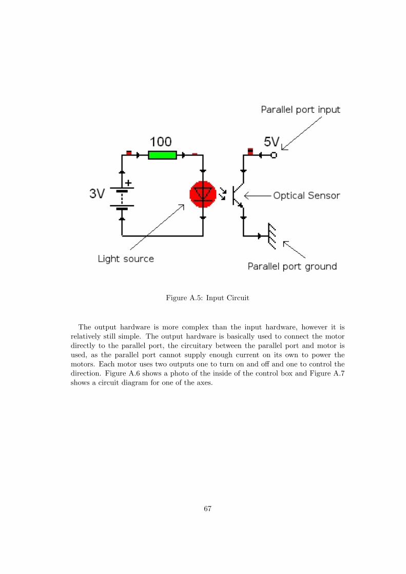
Figure A.5: Input Circuit
The output hardware is more complex than the input hardware, however it isrelatively still simple. The output hardware is basically used to connect the motordirectly to the parallel port, the circuitary between the parallel port and motor isused, as the parallel port cannot supply enough current on its own to power themotors. Each motor uses two outputs one to turn on and off and one to control thedirection. Figure A.6 shows a photo of the inside of the control box and Figure A.7shows a circuit diagram for one of the axes.
67
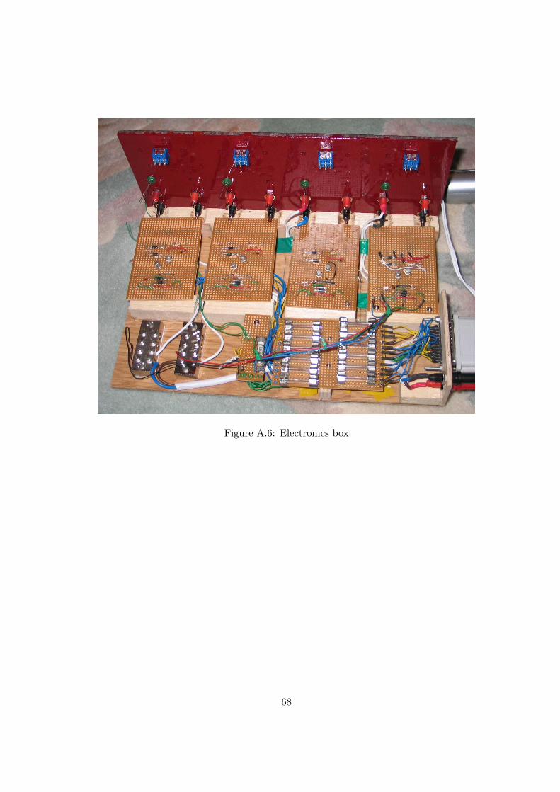
Figure A.6: Electronics box
68
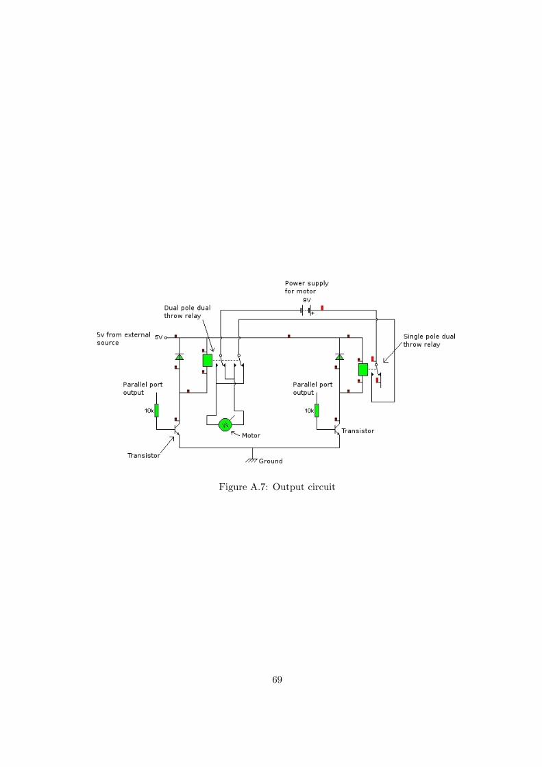
Figure A.7: Output circuit
69
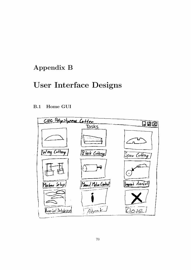
Appendix B
User Interface Designs
B.1 Home GUI
70
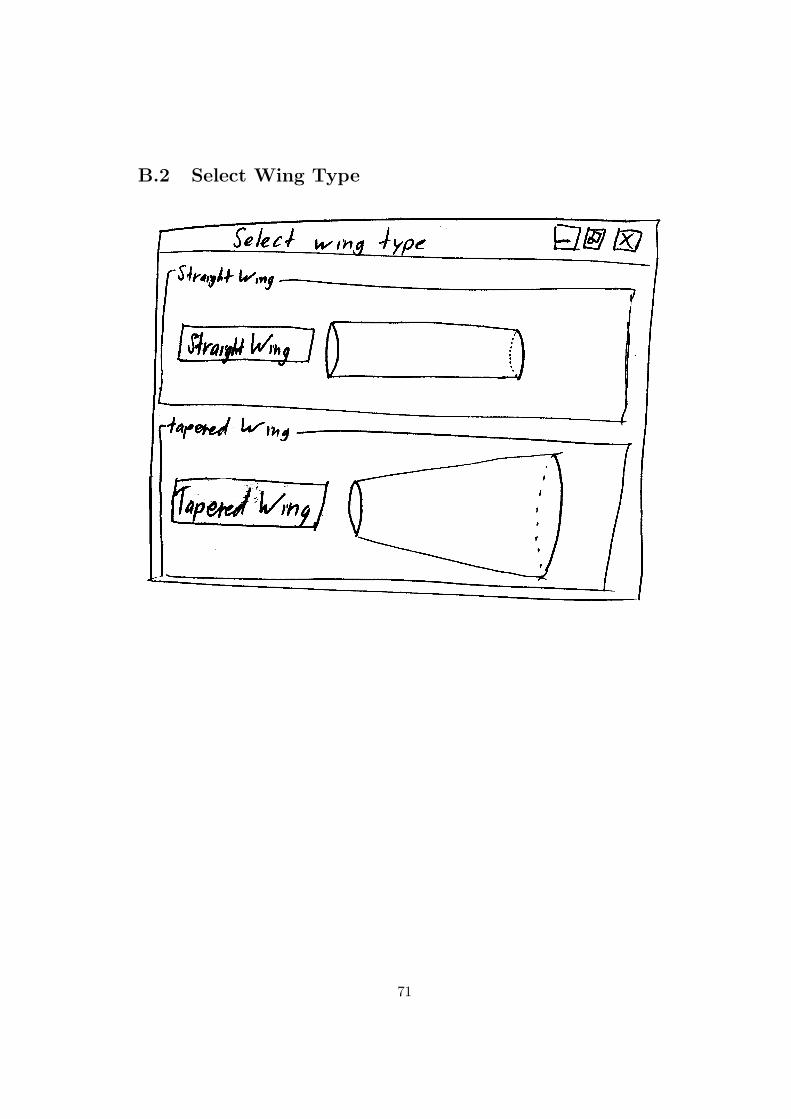
B.2 Select Wing Type
71

B.3 Straight Wing Setup
72
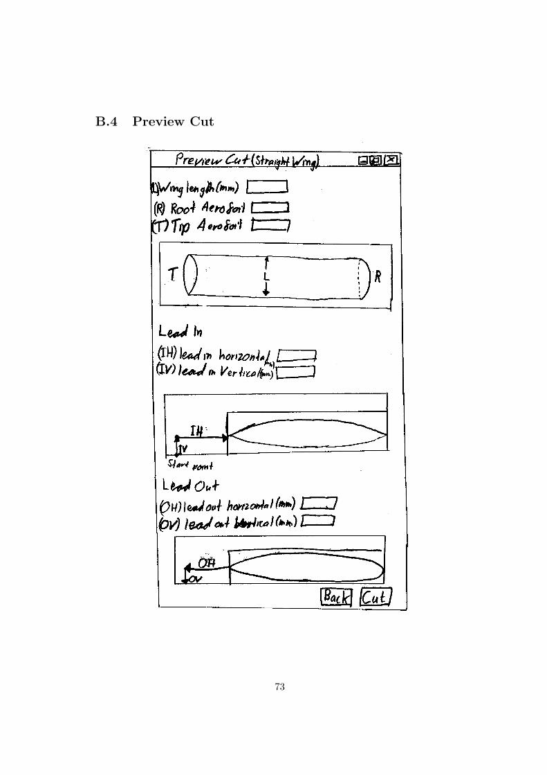
B.4 Preview Cut
73
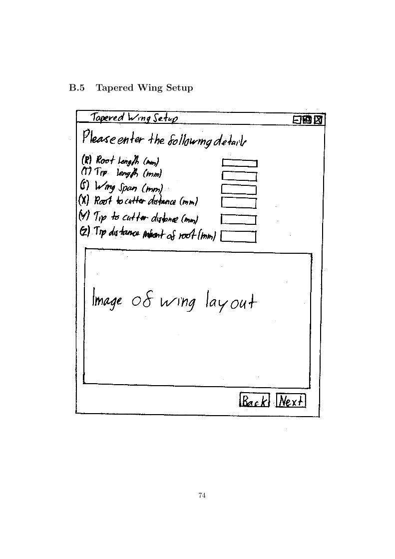
B.5 Tapered Wing Setup
74
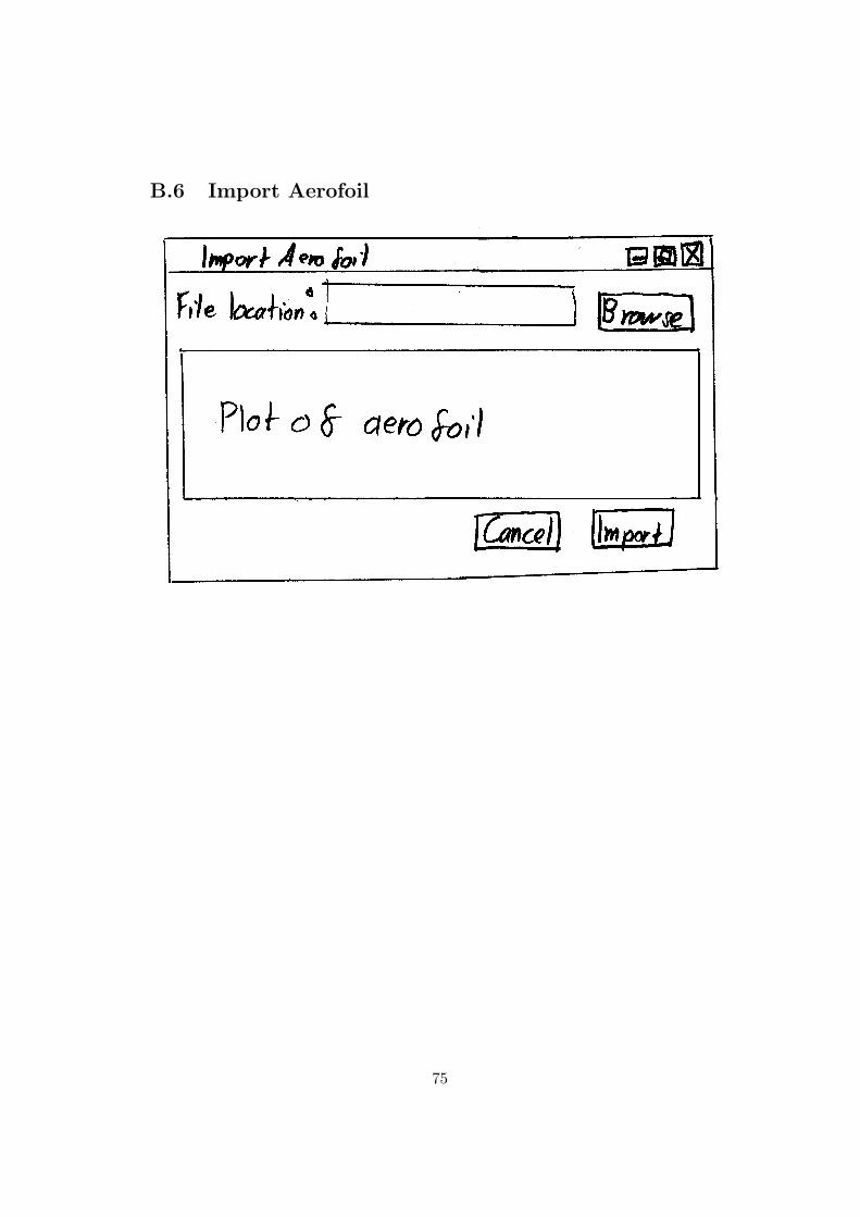
B.6 Import Aerofoil
75
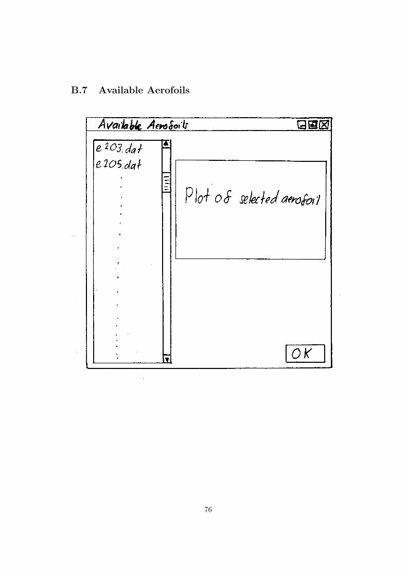
B.7 Available Aerofoils
76
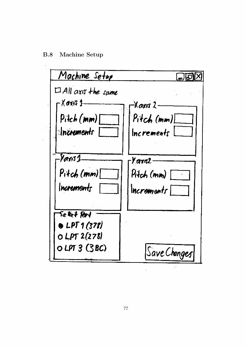
B.8 Machine Setup
77
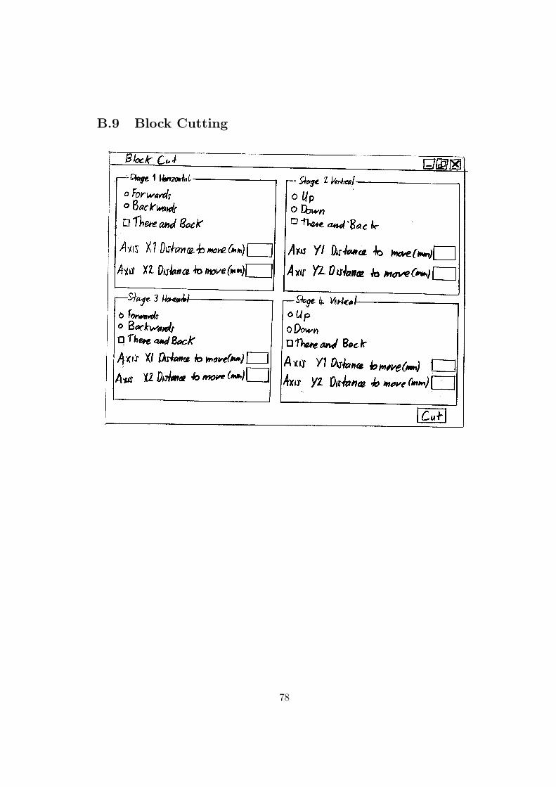
B.9 Block Cutting
78
Appendix C
Testing
C.1 Functional Requirments Validation
79
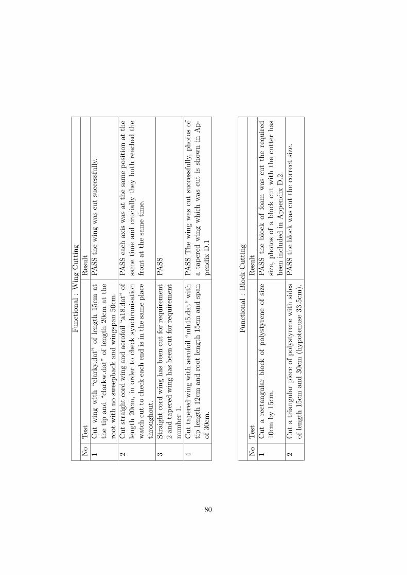
Func
tion
al:
Win
gC
utti
ngN
oTes
tR
esul
t1
Cut
win
gw
ith
“cla
rky.
dat”
ofle
ngth
15cm
atth
eti
pan
d“c
lark
w.d
at”
ofle
ngth
20cm
atth
ero
otw
ith
nosw
eepb
ack
and
win
gspa
n50
cm.
PASS
the
win
gw
ascu
tsu
cces
sful
ly.
2C
utst
raig
htco
rdw
ing
and
aero
foil
“a18
.dat
”of
leng
th20
cm,
inor
der
toch
eck
sync
hron
isat
ion
wat
chcu
tto
chec
kea
chen
dis
inth
esa
me
plac
eth
roug
hout
.
PASS
each
axis
was
atth
esa
me
posi
tion
atth
esa
me
tim
ean
dcr
ucia
llyth
eybo
thre
ache
dth
efr
ont
atth
esa
me
tim
e.
3St
raig
htco
rdw
ing
has
been
cut
for
requ
irem
ent
2an
dta
pere
dw
ing
hasbe
encu
tfo
rre
quir
emen
tnu
mbe
r1.
PASS
4C
utta
pere
dw
ing
wit
hae
rofo
il“m
h45.
dat“
wit
hti
ple
ngth
12cm
and
root
leng
th15
cman
dsp
anof
30cm
.
PASS
The
win
gw
ascu
tsu
cces
sful
ly,
phot
osof
ata
pere
dw
ing
whi
chw
ascu
tis
show
nin
Ap-
pend
ixD
.1
Func
tion
al:
Blo
ckC
utti
ngN
oTes
tR
esul
t1
Cut
are
ctan
gula
rbl
ock
ofpo
lyst
yren
eof
size
10cm
by15
cm.
PASS
the
bloc
kof
foam
was
cut
the
requ
ired
size
,ph
otos
ofa
bloc
kcu
tw
ith
the
cutt
erha
sbe
enin
clud
edin
App
endi
xD
.2.
2C
uta
tria
ngul
arpi
ece
ofpo
lyst
yren
ew
ith
side
sof
leng
th15
cman
d30
cm(h
ypot
enus
e33
.5cm
).PA
SSth
ebl
ock
was
cut
the
corr
ect
size
.
80
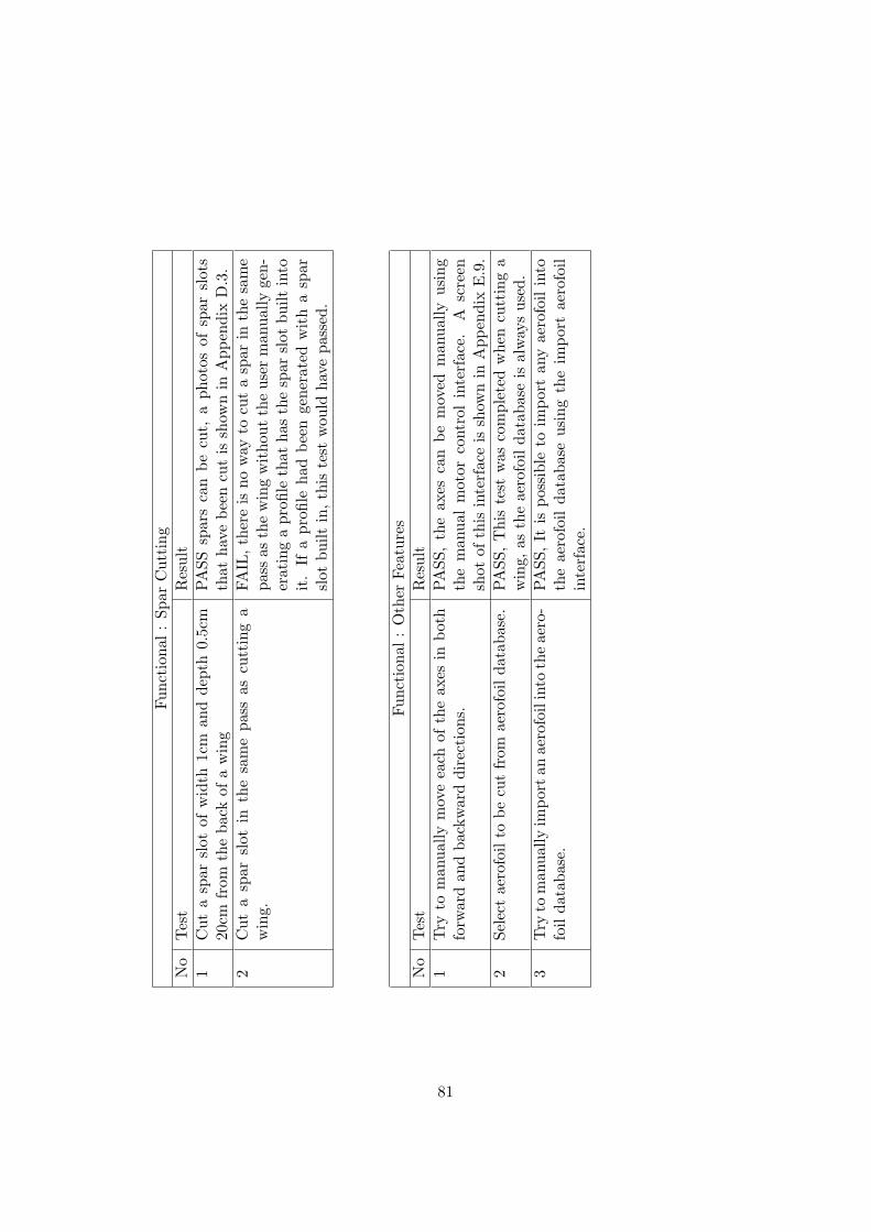
Func
tion
al:
Spar
Cut
ting
No
Tes
tR
esul
t1
Cut
asp
arsl
otof
wid
th1c
man
dde
pth
0.5c
m20
cmfr
omth
eba
ckof
aw
ing
PASS
spar
sca
nbe
cut,
aph
otos
ofsp
arsl
ots
that
have
been
cut
issh
own
inA
ppen
dix
D.3
.2
Cut
asp
arsl
otin
the
sam
epa
ssas
cutt
ing
aw
ing.
FAIL
,the
reis
now
ayto
cut
asp
arin
the
sam
epa
ssas
the
win
gw
itho
utth
eus
erm
anua
llyge
n-er
atin
ga
profi
leth
atha
sth
esp
arsl
otbu
iltin
toit
.If
apr
ofile
had
been
gene
rate
dw
ith
asp
arsl
otbu
iltin
,th
iste
stw
ould
have
pass
ed.
Func
tion
al:
Oth
erFe
atur
esN
oTes
tR
esul
t1
Try
tom
anua
llym
ove
each
ofth
eax
esin
both
forw
ard
and
back
war
ddi
rect
ions
.PA
SS,
the
axes
can
bem
oved
man
ually
usin
gth
em
anua
lm
otor
cont
rol
inte
rfac
e.A
scre
ensh
otof
this
inte
rfac
eis
show
nin
App
endi
xE
.9.
2Se
lect
aero
foil
tobe
cut
from
aero
foil
data
base
.PA
SS,T
his
test
was
com
plet
edw
hen
cutt
ing
aw
ing,
asth
eae
rofo
ilda
taba
seis
alw
ays
used
.3
Try
tom
anua
llyim
port
anae
rofo
ilin
toth
eae
ro-
foil
data
base
.PA
SS,It
ispo
ssib
leto
impo
rtan
yae
rofo
ilin
toth
eae
rofo
ilda
taba
seus
ing
the
impo
rtae
rofo
ilin
terf
ace.
81
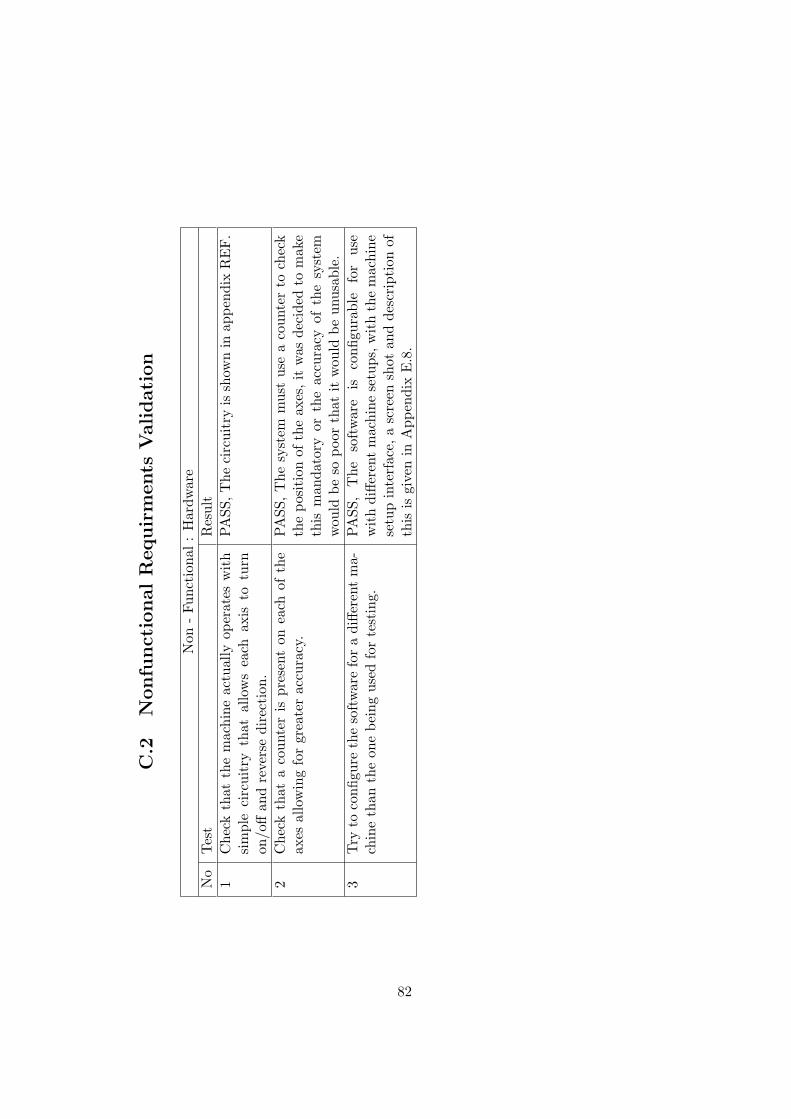
C.2
Nonfu
nct
ionalR
equir
ments
Validati
on
Non
-Fu
ncti
onal
:H
ardw
are
No
Tes
tR
esul
t1
Che
ckth
atth
em
achi
neac
tual
lyop
erat
esw
ith
sim
ple
circ
uitr
yth
atal
low
sea
chax
isto
turn
on/o
ffan
dre
vers
edi
rect
ion.
PASS
,The
circ
uitr
yis
show
nin
appe
ndix
RE
F.
2C
heck
that
aco
unte
ris
pres
ent
onea
chof
the
axes
allo
win
gfo
rgr
eate
rac
cura
cy.
PASS
,T
hesy
stem
mus
tus
ea
coun
ter
toch
eck
the
posi
tion
ofth
eax
es,i
tw
asde
cide
dto
mak
eth
ism
anda
tory
orth
eac
cura
cyof
the
syst
emw
ould
beso
poor
that
itw
ould
beun
usab
le.
3Try
toco
nfigu
reth
eso
ftw
are
for
adi
ffere
ntm
a-ch
ine
than
the
one
bein
gus
edfo
rte
stin
g.PA
SS,
The
soft
war
eis
confi
gura
ble
for
use
wit
hdi
ffere
ntm
achi
nese
tups
,wit
hth
em
achi
nese
tup
inte
rfac
e,a
scre
ensh
otan
dde
scri
ptio
nof
this
isgi
ven
inA
ppen
dix
E.8
.
82
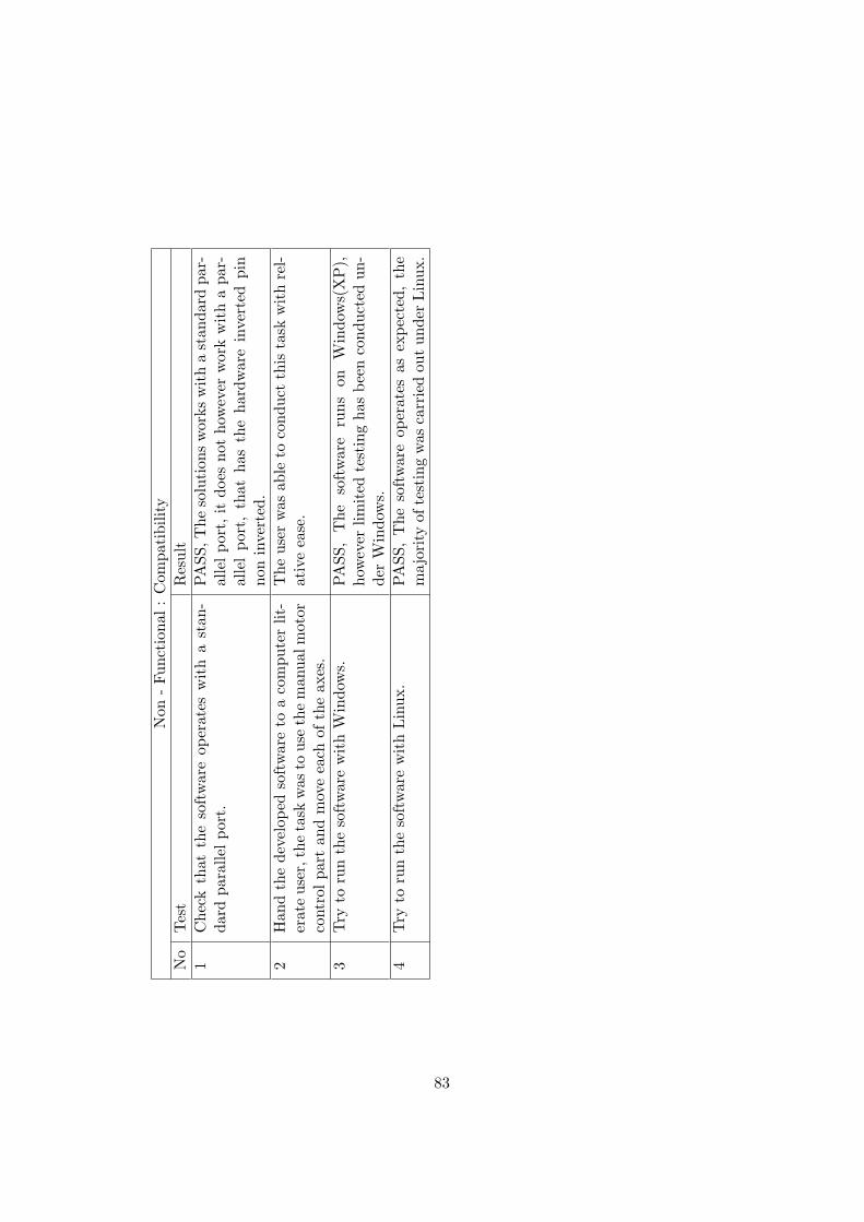
Non
-Fu
ncti
onal
:C
ompa
tibi
lity
No
Tes
tR
esul
t1
Che
ckth
atth
eso
ftw
are
oper
ates
wit
ha
stan
-da
rdpa
ralle
lpo
rt.
PASS
,The
solu
tion
sw
orks
wit
ha
stan
dard
par-
alle
lpo
rt,it
does
not
how
ever
wor
kw
ith
apa
r-al
lel
port
,th
atha
sth
eha
rdw
are
inve
rted
pin
non
inve
rted
.2
Han
dth
ede
velo
ped
soft
war
eto
aco
mpu
ter
lit-
erat
eus
er,t
heta
skw
asto
use
the
man
ualm
otor
cont
rolpa
rtan
dm
ove
each
ofth
eax
es.
The
user
was
able
toco
nduc
tth
ista
skw
ith
rel-
ativ
eea
se.
3Try
toru
nth
eso
ftw
are
wit
hW
indo
ws.
PASS
,T
heso
ftw
are
runs
onW
indo
ws(
XP
),ho
wev
erlim
ited
test
ing
has
been
cond
ucte
dun
-de
rW
indo
ws.
4Try
toru
nth
eso
ftw
are
wit
hLin
ux.
PASS
,T
heso
ftw
are
oper
ates
asex
pect
ed,
the
maj
ority
ofte
stin
gw
asca
rrie
dou
tun
der
Lin
ux.
83
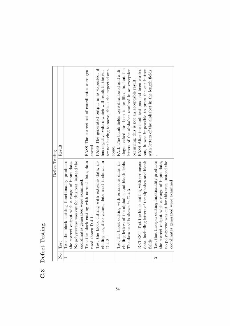
C.3
Defe
ctTest
ing
Def
ect
Tes
ting
No
Tes
tR
esul
t1
Tes
tth
ebl
ock
cutt
ing
func
tion
ality
prod
uces
the
corr
ect
outp
utw
ith
ara
nge
ofin
put
data
.N
opo
lyst
yren
ew
ascu
tfo
rth
iste
st,i
nste
adth
eco
ordi
nate
sge
nera
ted
wer
eex
amin
ed.
Tes
tth
ebl
ock
cutt
ing
wit
hno
rmal
data
,da
taus
edsh
own
D.4
.1.
PASS
The
corr
ect
set
ofco
ordi
nate
sw
ere
gen-
erat
ed.
Tes
tth
ebl
ock
cutt
ing
wit
hex
trem
eda
ta,
in-
clud
ing
nega
tive
valu
es,
data
used
issh
own
inD
.4.2
.
PASS
The
gene
rate
dou
tput
isas
expe
cted
,it
has
nega
tive
valu
esw
hich
will
resu
ltin
the
cut-
ter
not
havi
ngto
mov
e,th
isis
the
expe
cted
out-
com
e.Tes
tth
ebl
ock
cutt
ing
wit
her
rone
ous
data
,in
-cl
udin
gle
tter
sof
the
alph
abet
and
blan
kfie
lds.
The
data
used
issh
own
inD
.4.3
.
FAIL
The
blan
kfie
lds
wer
edi
sallo
wed
and
adi
-al
ogue
aske
dfo
rth
emto
befil
led
in,
but
the
lett
ers
ofth
eal
phab
etre
sult
edin
anex
cept
ion
occu
rrin
g,th
isis
not
anac
cept
able
resu
lt.
RE
TE
ST:T
estth
ebl
ock
cutt
ing
wit
her
rone
ous
data
,inc
ludi
ngle
tter
sof
the
alph
abet
and
blan
kfie
lds.
PASS
Aft
erth
em
odifi
cati
ons
had
been
carr
ied
out,
itw
asim
poss
ible
topr
ess
the
cut
butt
onw
ith
lett
ers
ofth
eal
phab
etin
the
leng
thfie
lds
2Tes
tth
atth
esp
arcu
ttin
gfu
ncti
onal
ity
prod
uces
the
corr
ect
outp
utw
ith
ara
nge
ofin
put
data
,no
poly
styr
ene
was
cut
for
this
test
,ins
tead
the
coor
dina
tes
gene
rate
dw
ere
exam
ined
.
84
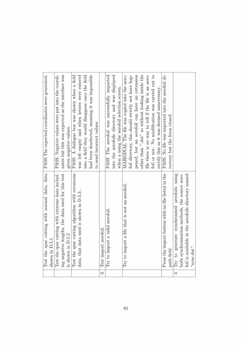
Tes
tth
esp
arcu
ttin
gw
ith
norm
alda
ta,
data
show
nin
D.5
.1PA
SST
heex
pect
edco
ordi
nate
sw
ere
gene
rate
d.
Tes
tth
esp
arcu
ttin
gw
ith
extr
eme
data
incl
ud-
ing
nega
tive
leng
ths,
the
data
used
for
this
test
issh
own
inD
.5.2
PASS
.Neg
ativ
eva
lues
wer
epu
tin
toth
eco
ordi
-na
tes
but
this
was
expe
cted
asth
ein
terf
ace
was
give
nne
gati
veva
lues
.Tes
tth
esp
arcu
ttin
gal
gori
thm
wit
her
rone
ous
data
,th
atda
taus
edis
show
nin
D.5
.3.
PASS
.A
dial
ogue
box
was
show
nw
hen
afie
ldw
asle
ftem
pty
and
whe
nle
tter
sw
ere
ente
red
into
afie
ldth
eyw
ould
disa
ppea
ron
ceth
efie
ldha
dbe
ende
sele
cted
,m
eani
ngit
was
impo
ssib
leto
send
inco
rrec
tva
lues
.3
Tes
tim
port
aero
foil.
Try
toim
port
ava
lidae
rofo
il.PA
SST
heae
rofo
ilw
assu
cces
sful
lyim
port
edin
toth
eae
rofo
ilsdi
rect
ory
and
was
disp
laye
dw
hen
aus
ing
the
aero
foil
sele
ctio
nsc
reen
.Try
toim
port
afil
eth
atis
not
anae
rofo
il.M
AR
GIN
AL
The
file
was
copi
edin
toth
eae
ro-
foil
dire
ctor
y,th
issh
ould
stri
ctly
not
have
hap-
pene
d,bu
tan
aero
foil
can
have
anex
tens
ion
othe
rth
an”.
dat”
sow
itho
utlo
okin
gin
side
the
file
ther
eis
now
ayto
tell
ifth
efil
eis
anae
ro-
foil
orno
t.N
om
odifi
cati
onw
asca
rrie
dou
tto
rect
ifyth
isas
itw
asde
emed
unne
cess
ary.
Pre
ssth
eim
port
butt
onw
ith
nofil
elis
ted
inth
epa
thfie
ld.
PASS
.No
file
was
impo
rted
into
the
aero
foil
di-
rect
ory
but
the
form
clos
ed.
4Try
toge
nera
tesy
nchr
onis
edae
rofo
ilsus
ing
both
sync
hron
isat
ion
met
hods
,th
eso
urce
aero
-fo
ilis
avai
labl
ein
the
aero
foils
dire
ctor
yna
med
“syn
c.da
t“.
85
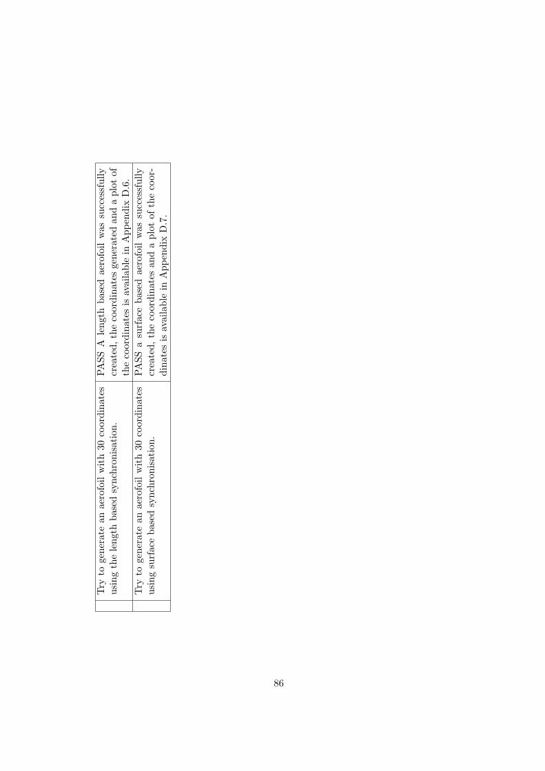
Try
toge
nera
tean
aero
foil
wit
h30
coor
dina
tes
usin
gth
ele
ngth
base
dsy
nchr
onis
atio
n.PA
SSA
leng
thba
sed
aero
foil
was
succ
essf
ully
crea
ted,
the
coor
dina
tes
gene
rate
dan
da
plot
ofth
eco
ordi
nate
sis
avai
labl
ein
App
endi
xD
.6.
Try
toge
nera
tean
aero
foil
wit
h30
coor
dina
tes
usin
gsu
rfac
eba
sed
sync
hron
isat
ion.
PASS
asu
rfac
eba
sed
aero
foil
was
succ
essf
ully
crea
ted,
the
coor
dina
tes
and
apl
otof
the
coor
-di
nate
sis
avai
labl
ein
App
endi
xD
.7.
86
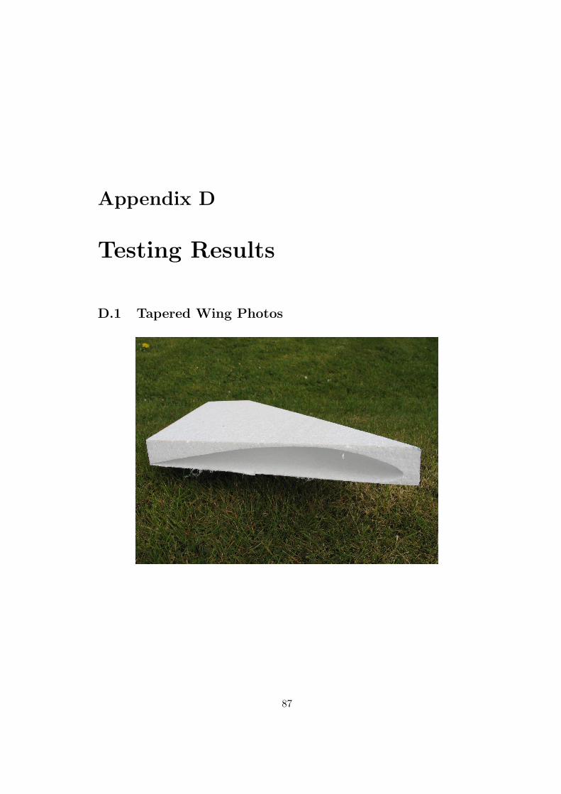
Appendix D
Testing Results
D.1 Tapered Wing Photos
87
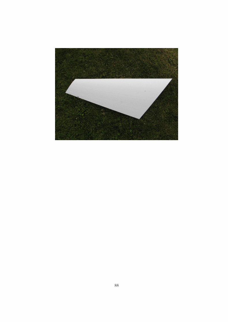
88
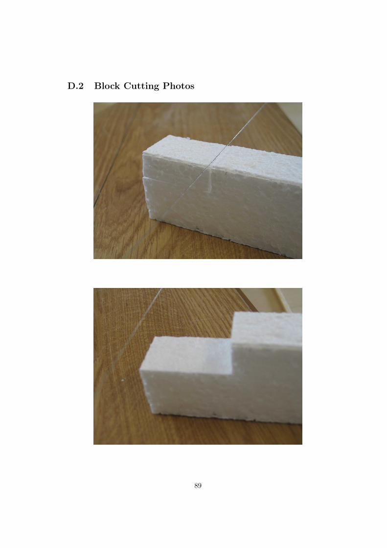
D.2 Block Cutting Photos
89
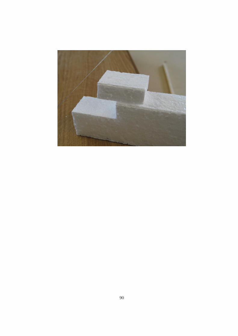
90
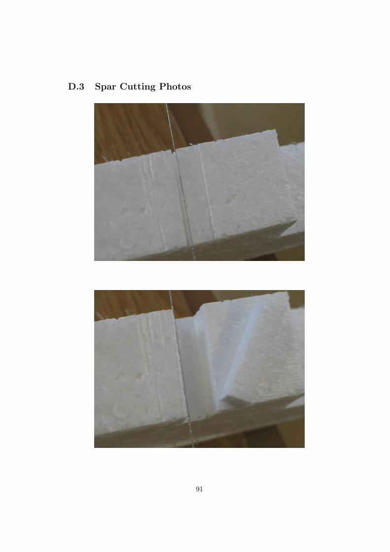
D.3 Spar Cutting Photos
91
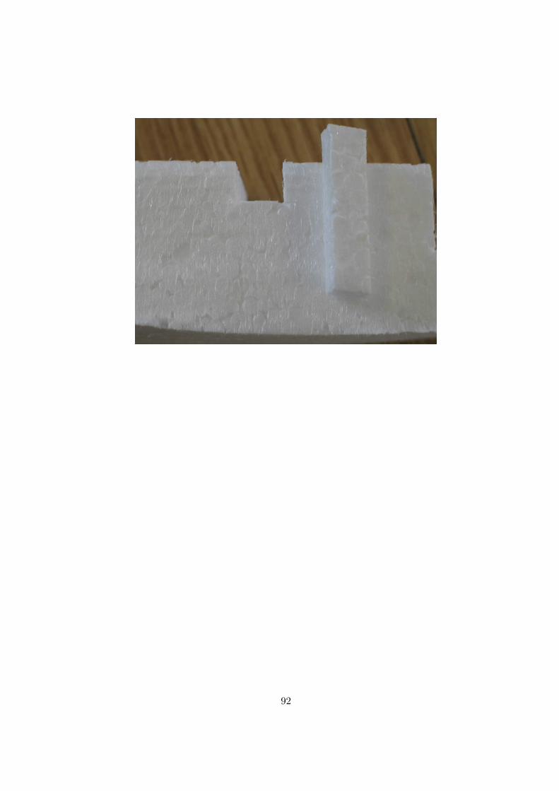
92
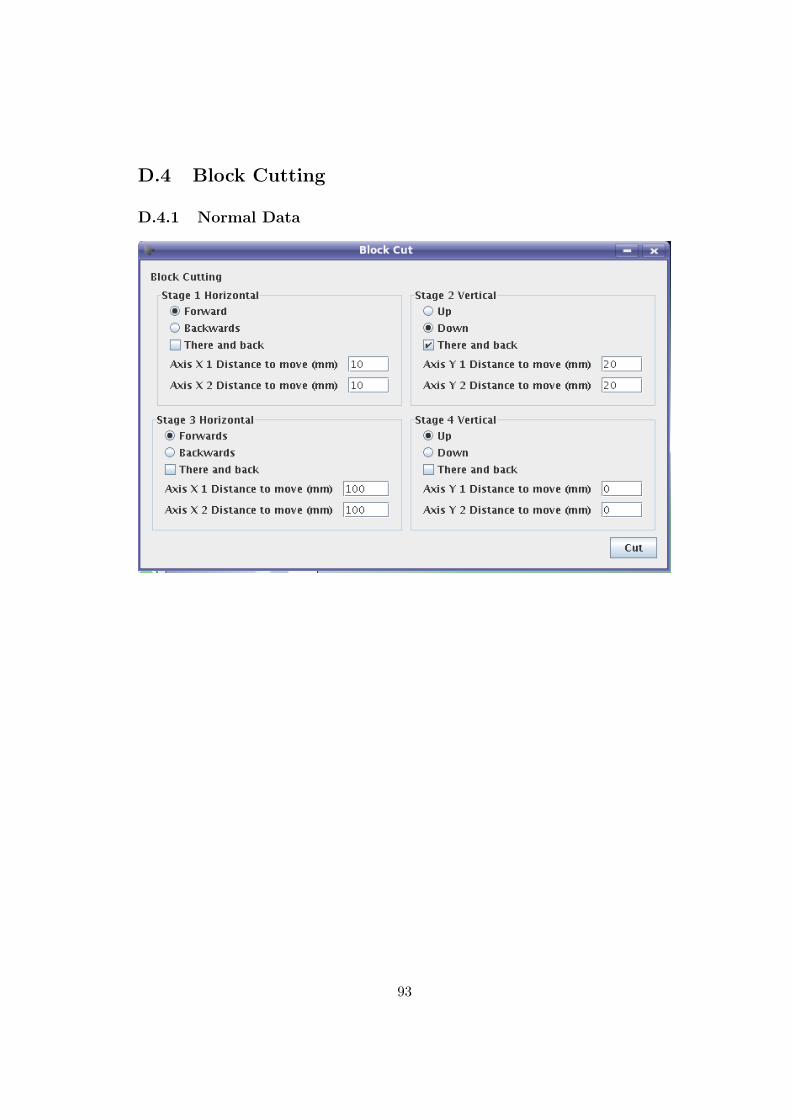
D.4 Block Cutting
D.4.1 Normal Data
93
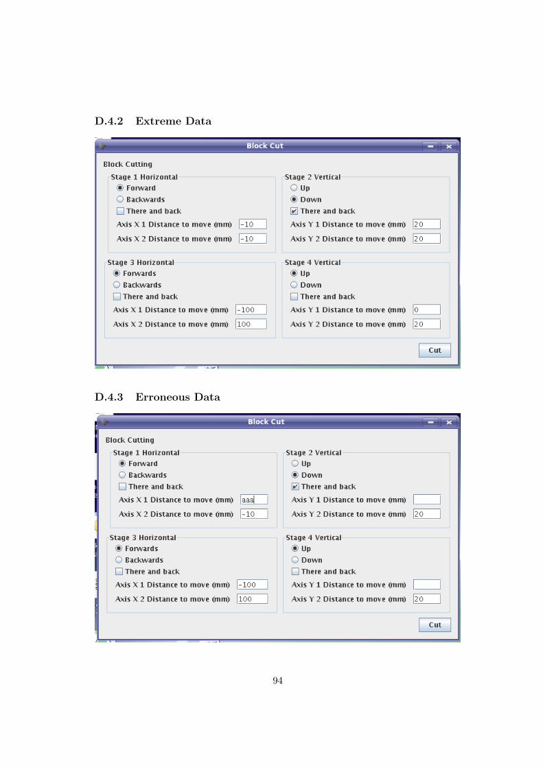
D.4.2 Extreme Data
D.4.3 Erroneous Data
94
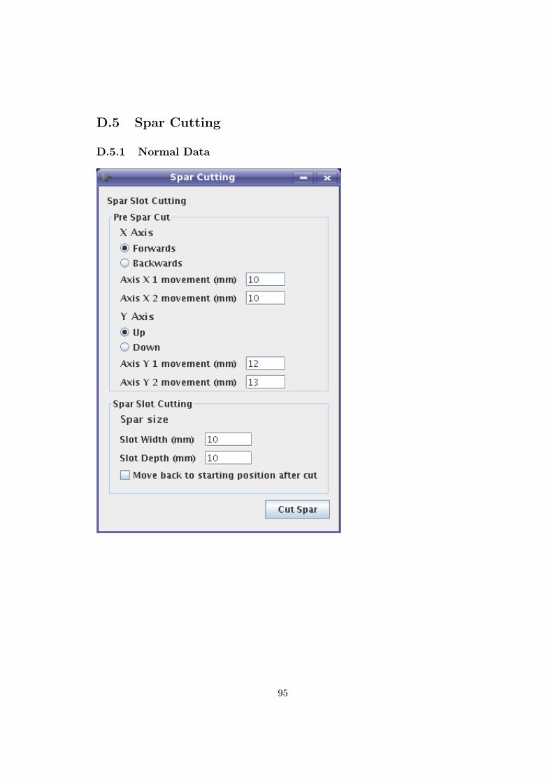
D.5 Spar Cutting
D.5.1 Normal Data
95
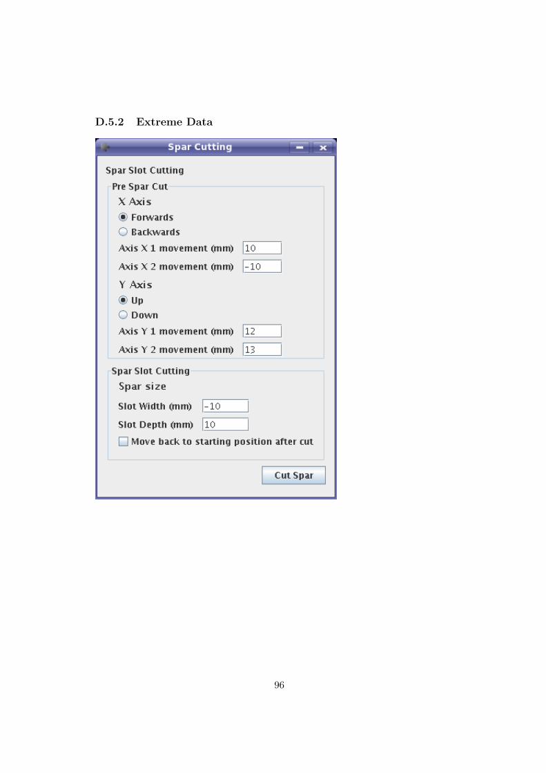
D.5.2 Extreme Data
96
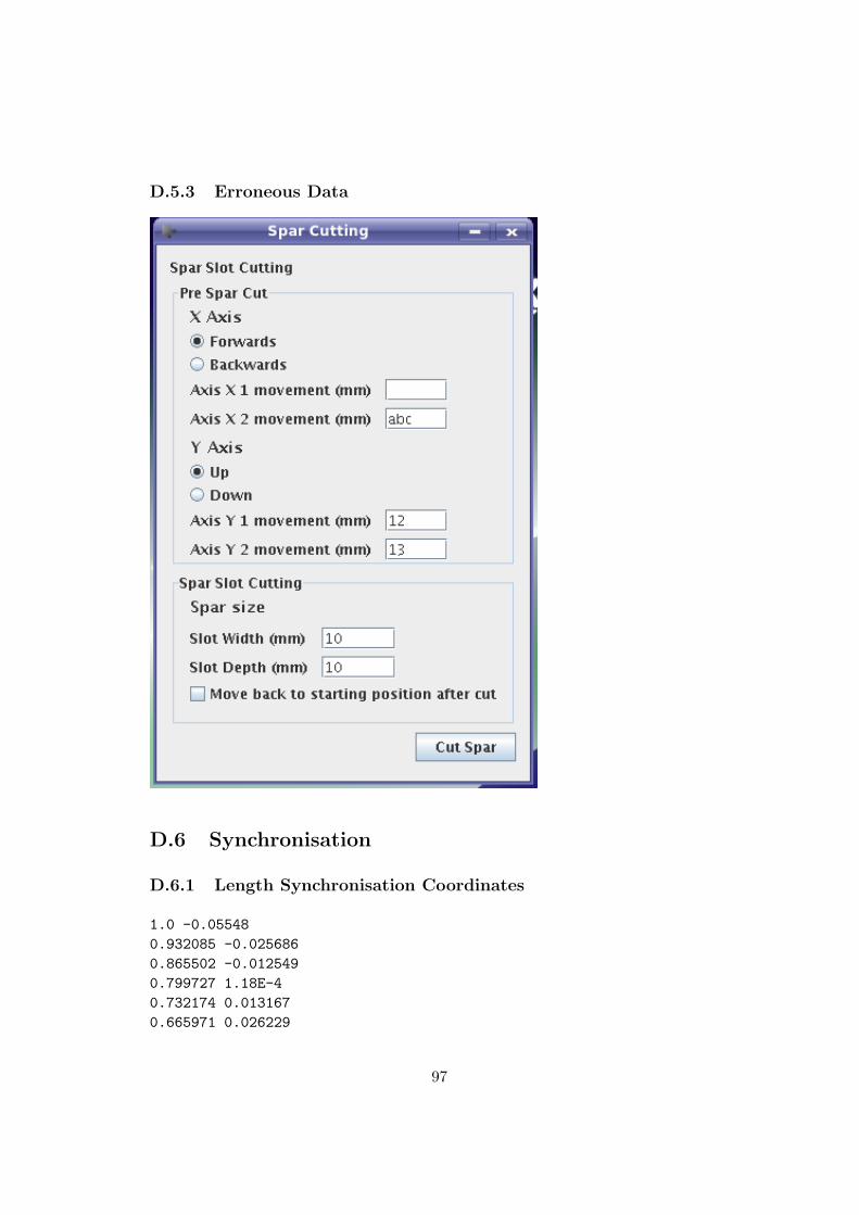
D.5.3 Erroneous Data
D.6 Synchronisation
D.6.1 Length Synchronisation Coordinates
1.0 -0.055480.932085 -0.0256860.865502 -0.0125490.799727 1.18E-40.732174 0.0131670.665971 0.026229
97
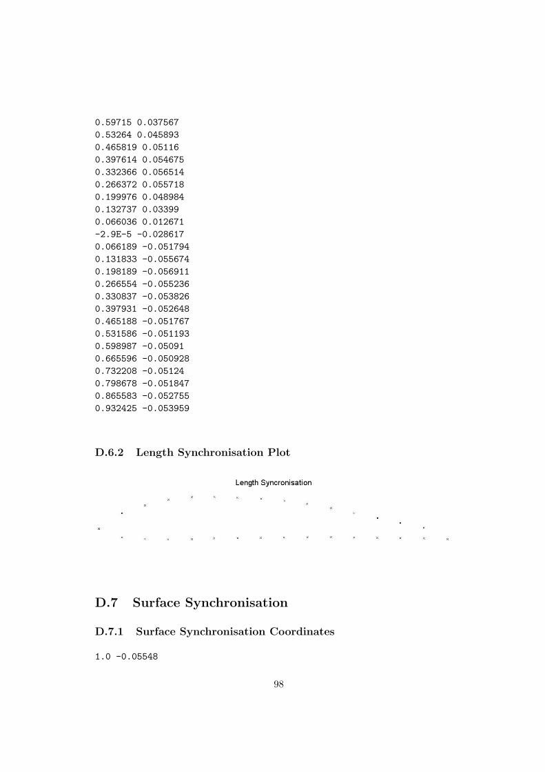
0.59715 0.0375670.53264 0.0458930.465819 0.051160.397614 0.0546750.332366 0.0565140.266372 0.0557180.199976 0.0489840.132737 0.033990.066036 0.012671-2.9E-5 -0.0286170.066189 -0.0517940.131833 -0.0556740.198189 -0.0569110.266554 -0.0552360.330837 -0.0538260.397931 -0.0526480.465188 -0.0517670.531586 -0.0511930.598987 -0.050910.665596 -0.0509280.732208 -0.051240.798678 -0.0518470.865583 -0.0527550.932425 -0.053959
D.6.2 Length Synchronisation Plot
D.7 Surface Synchronisation
D.7.1 Surface Synchronisation Coordinates
1.0 -0.05548
98
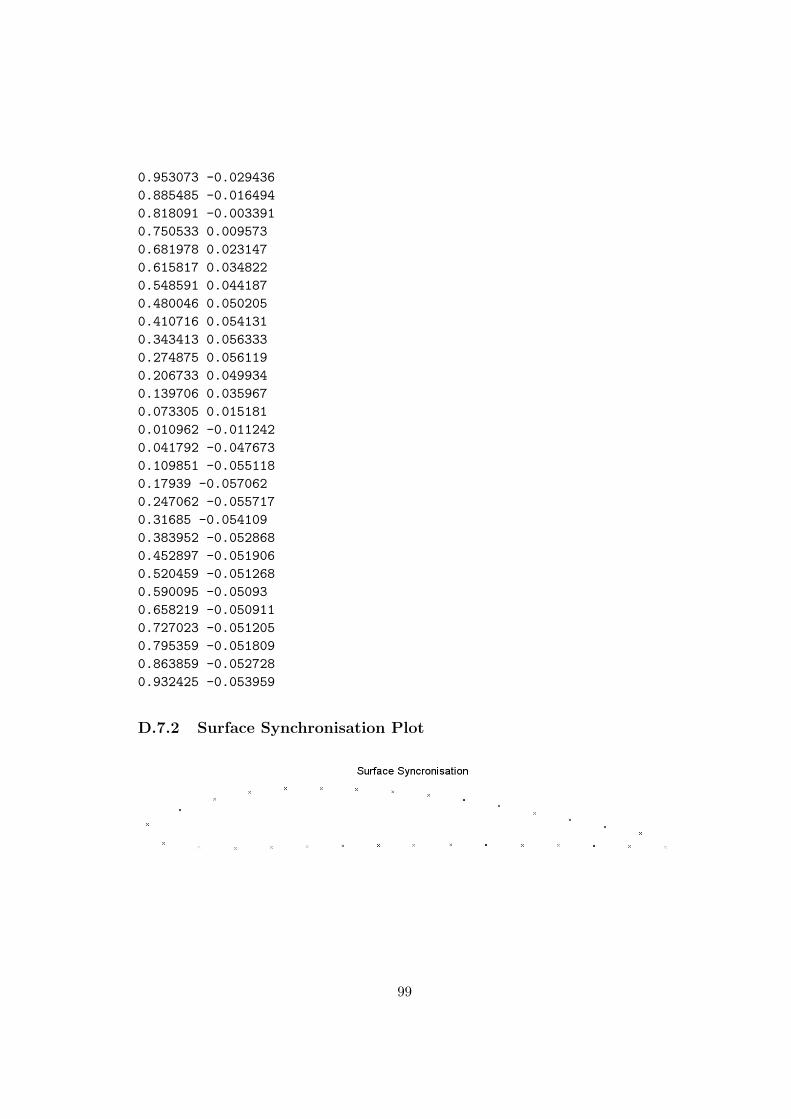
0.953073 -0.0294360.885485 -0.0164940.818091 -0.0033910.750533 0.0095730.681978 0.0231470.615817 0.0348220.548591 0.0441870.480046 0.0502050.410716 0.0541310.343413 0.0563330.274875 0.0561190.206733 0.0499340.139706 0.0359670.073305 0.0151810.010962 -0.0112420.041792 -0.0476730.109851 -0.0551180.17939 -0.0570620.247062 -0.0557170.31685 -0.0541090.383952 -0.0528680.452897 -0.0519060.520459 -0.0512680.590095 -0.050930.658219 -0.0509110.727023 -0.0512050.795359 -0.0518090.863859 -0.0527280.932425 -0.053959
D.7.2 Surface Synchronisation Plot
99

Appendix E
Screen Shots
The screen shots of the program are included in this Appendix so that an overviewof the operation of the program can be observed.
100
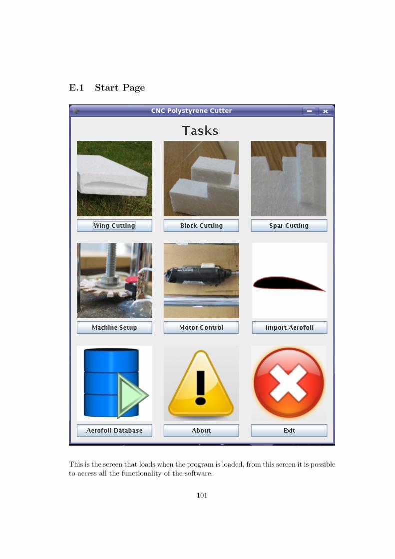
E.1 Start Page
This is the screen that loads when the program is loaded, from this screen it is possibleto access all the functionality of the software.
101
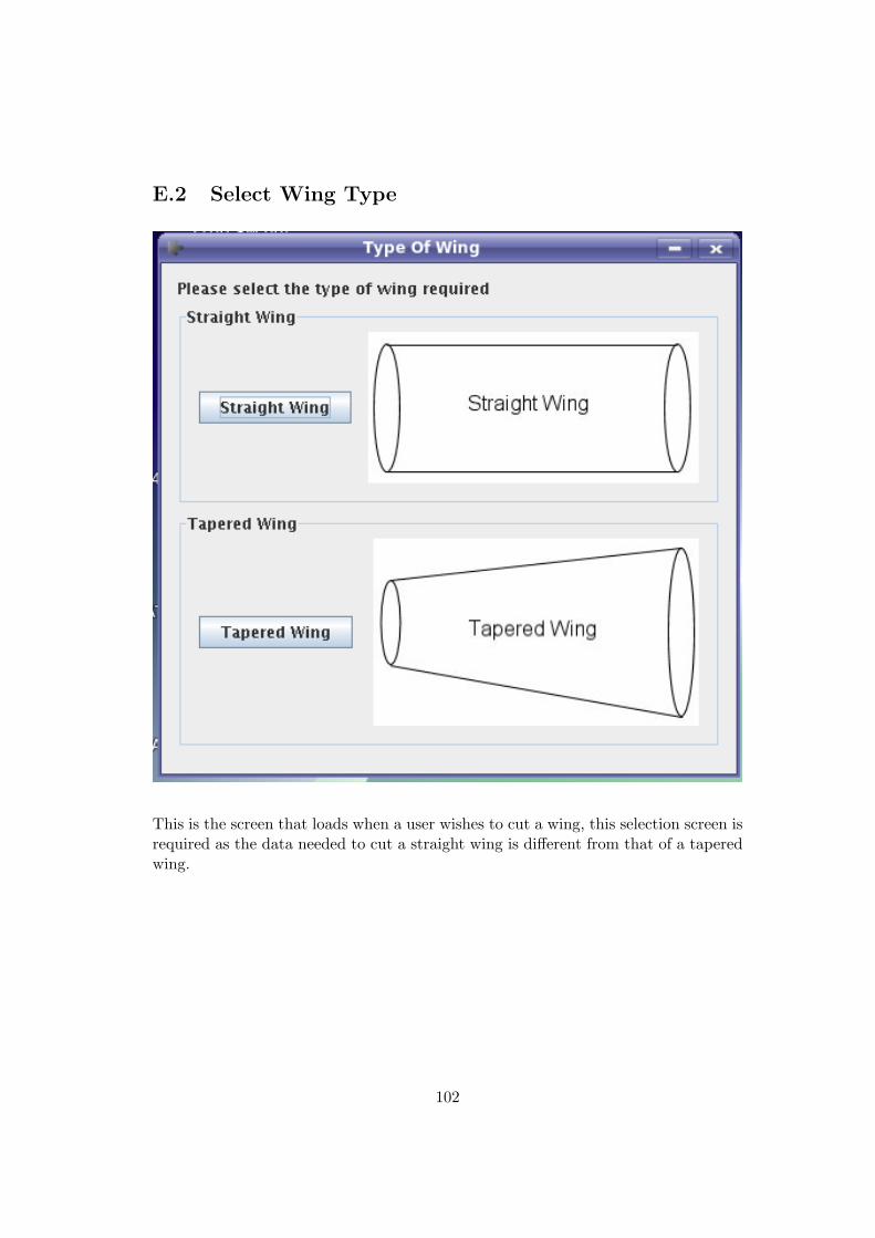
E.2 Select Wing Type
This is the screen that loads when a user wishes to cut a wing, this selection screen isrequired as the data needed to cut a straight wing is different from that of a taperedwing.
102
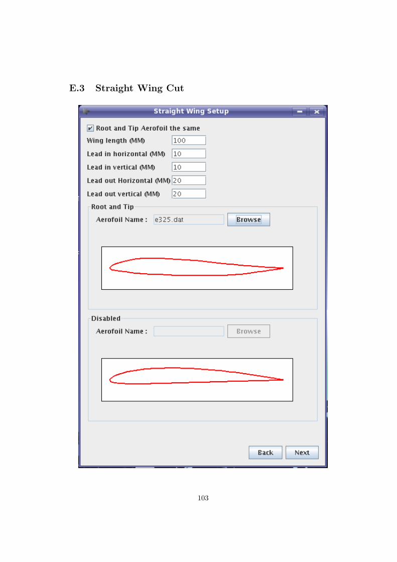
E.3 Straight Wing Cut
103
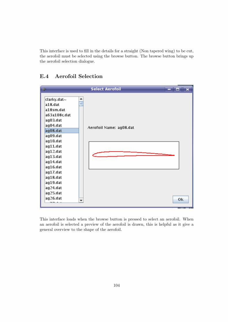
This interface is used to fill in the details for a straight (Non tapered wing) to be cut,the aerofoil must be selected using the browse button. The browse button brings upthe aerofoil selection dialogue.
E.4 Aerofoil Selection
This interface loads when the browse button is pressed to select an aerofoil. Whenan aerofoil is selected a preview of the aerofoil is drawn, this is helpful as it give ageneral overview to the shape of the aerofoil.
104
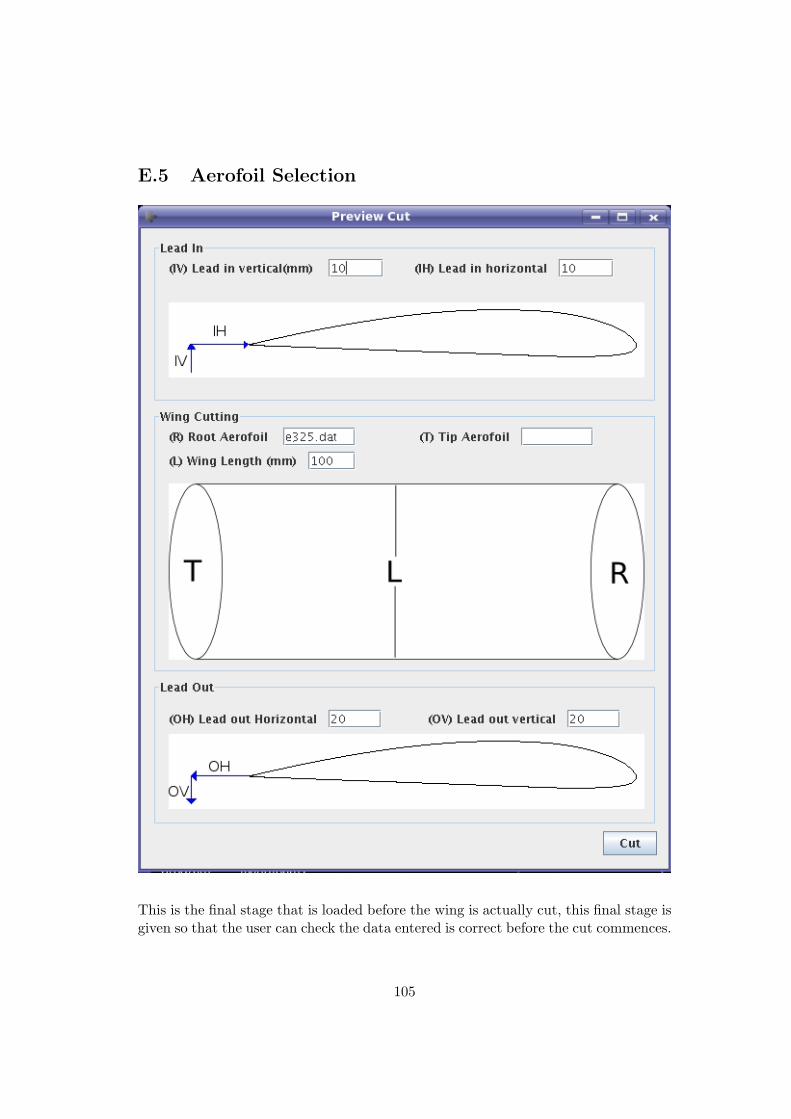
E.5 Aerofoil Selection
This is the final stage that is loaded before the wing is actually cut, this final stage isgiven so that the user can check the data entered is correct before the cut commences.
105
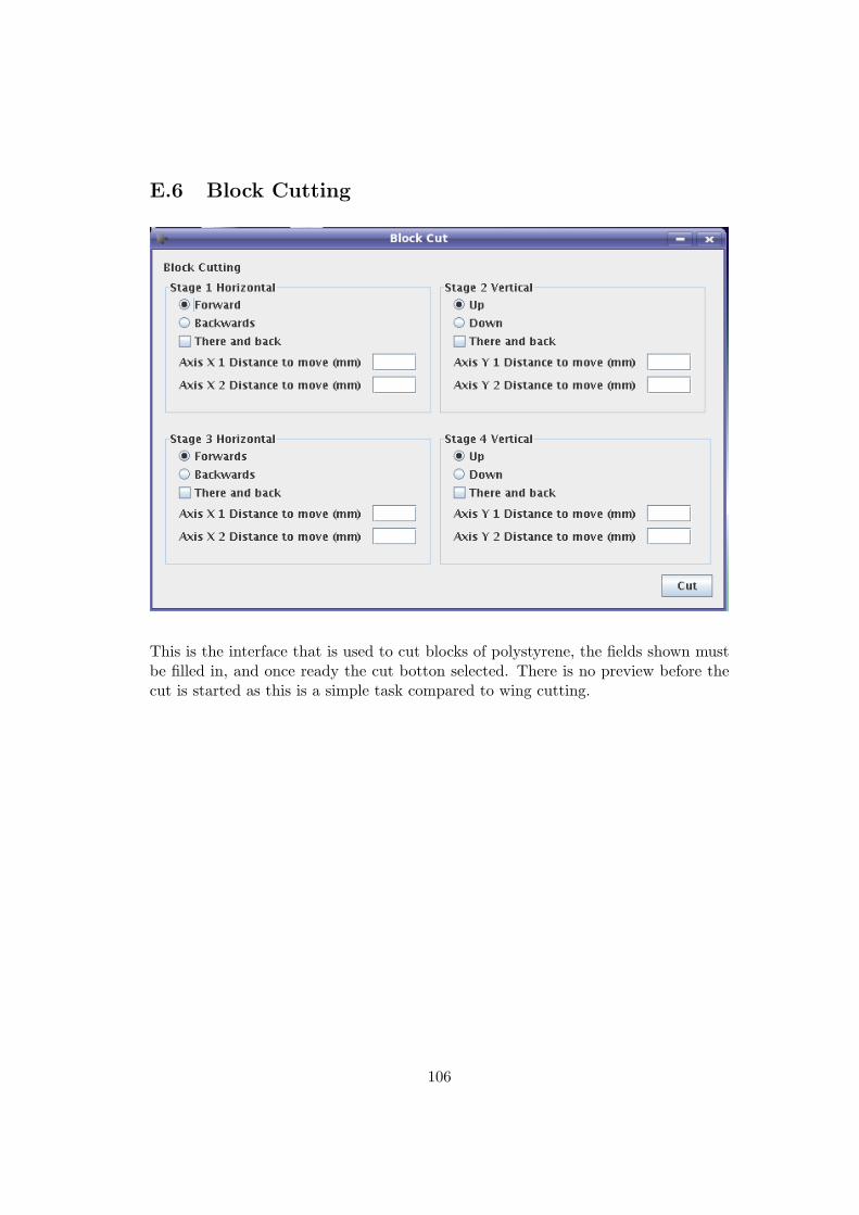
E.6 Block Cutting
This is the interface that is used to cut blocks of polystyrene, the fields shown mustbe filled in, and once ready the cut botton selected. There is no preview before thecut is started as this is a simple task compared to wing cutting.
106
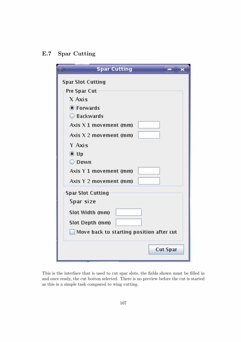
E.7 Spar Cutting
This is the interface that is used to cut spar slots, the fields shown must be filled inand once ready, the cut botton selected. There is no preview before the cut is startedas this is a simple task compared to wing cutting.
107
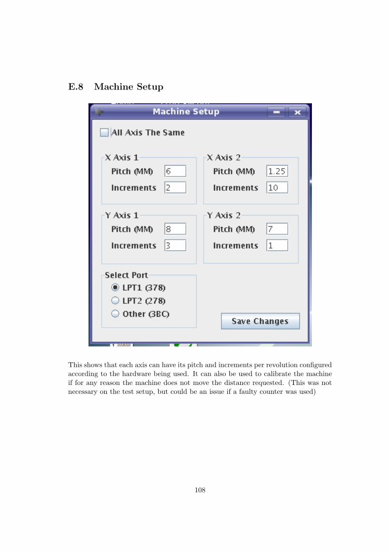
E.8 Machine Setup
This shows that each axis can have its pitch and increments per revolution configuredaccording to the hardware being used. It can also be used to calibrate the machineif for any reason the machine does not move the distance requested. (This was notnecessary on the test setup, but could be an issue if a faulty counter was used)
108
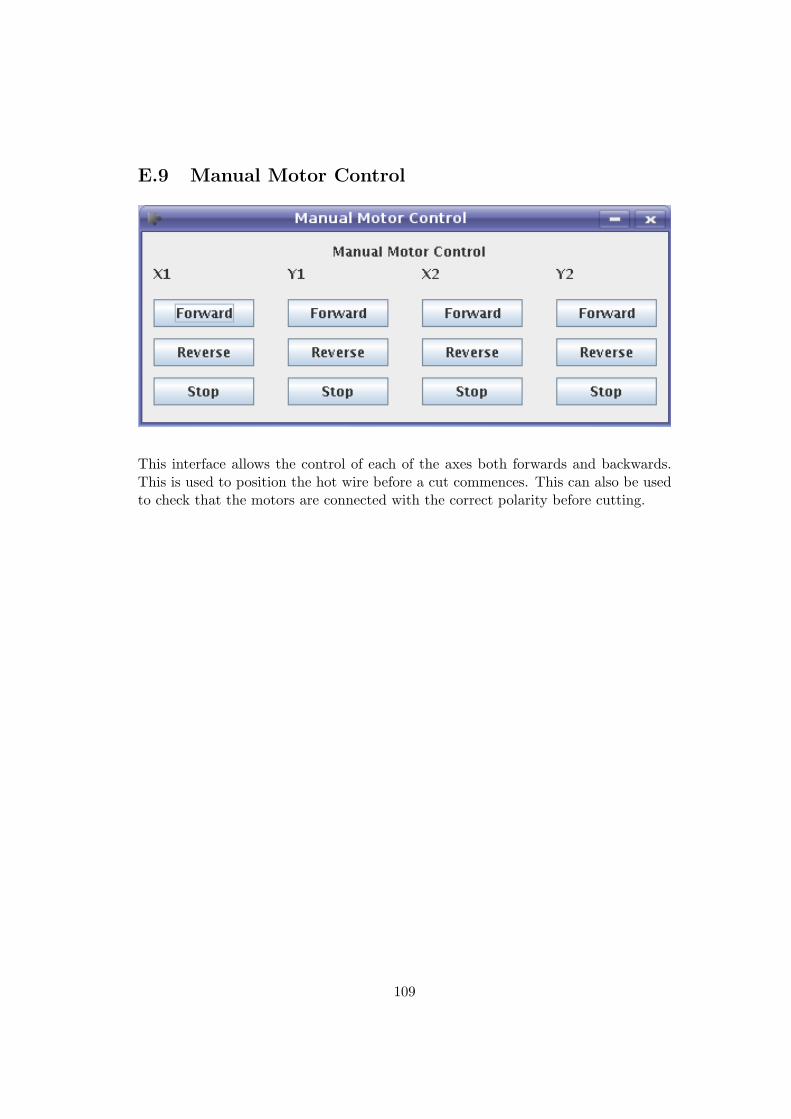
E.9 Manual Motor Control
This interface allows the control of each of the axes both forwards and backwards.This is used to position the hot wire before a cut commences. This can also be usedto check that the motors are connected with the correct polarity before cutting.
109
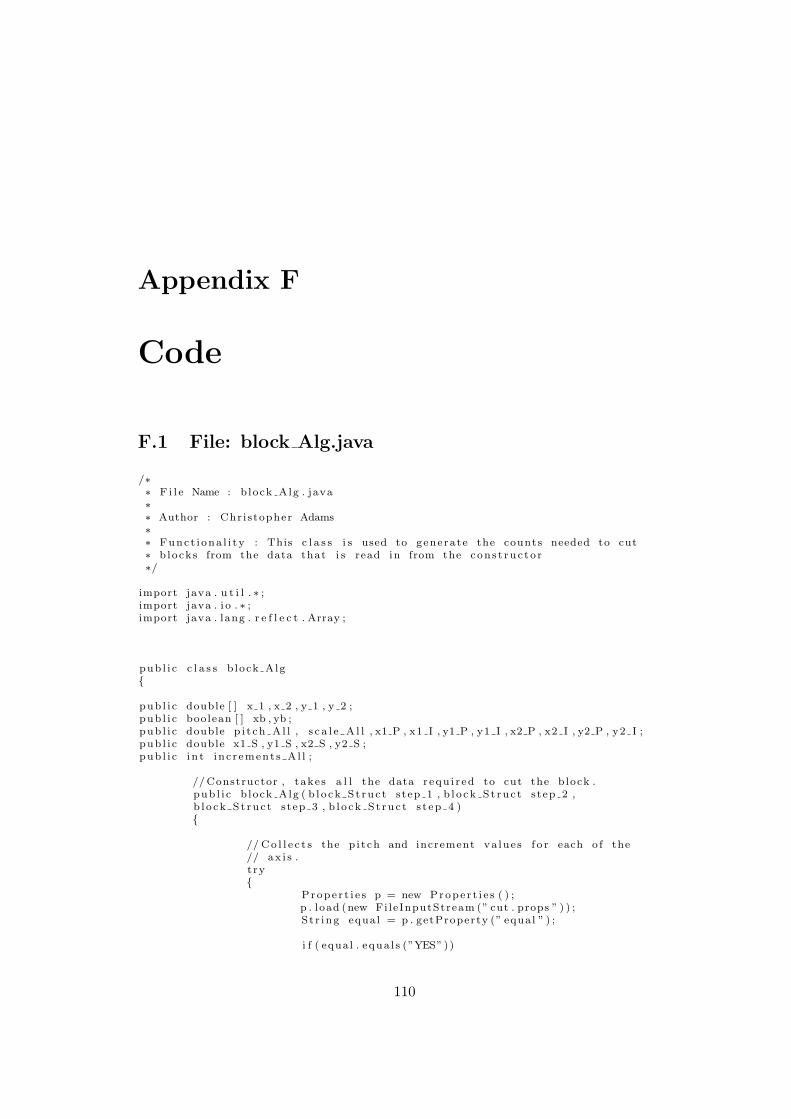
Appendix F
Code
F.1 File: block Alg.java
/∗∗ F i l e Name : b lock Alg . java∗∗ Author : Chr i s topher Adams∗∗ Func t i ona l i t y : This c l a s s i s used to generate the counts needed to cut∗ b locks from the data that i s read in from the con s t ruc to r∗/
import java . u t i l . ∗ ;import java . i o . ∗ ;import java . lang . r e f l e c t . Array ;
pub l i c c l a s s b lock Alg{
pub l i c double [ ] x 1 , x 2 , y 1 , y 2 ;pub l i c boolean [ ] xb , yb ;pub l i c double p i t ch A l l , s c a l e A l l , x1 P , x1 I , y1 P , y1 I , x2 P , x2 I , y2 P , y2 I ;pub l i c double x1 S , y1 S , x2 S , y2 S ;pub l i c i n t in c r ement s A l l ;
// Constructor , takes a l l the data r equ i r ed to cut the block .pub l i c b lock Alg ( b l o ck S t ruc t step 1 , b l o ck S t ruc t step 2 ,b l o ck S t ruc t step 3 , b l o ck S t ruc t s t ep 4 ){
// Co l l e c t s the p i t ch and increment va lue s f o r each o f the// ax i s .t ry{
Prope r t i e s p = new Prope r t i e s ( ) ;p . load (new Fi leInputStream (” cut . props ” ) ) ;S t r ing equal = p . getProperty (” equal ” ) ;
i f ( equal . equa l s (”YES”) )
110
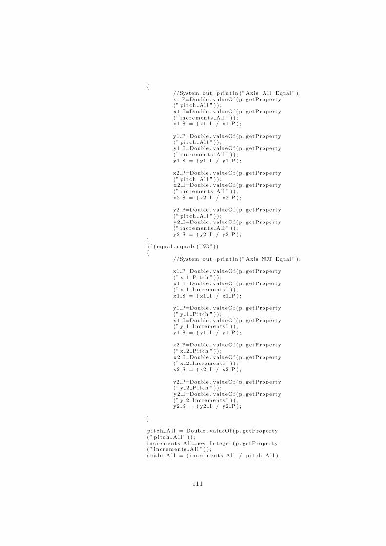
{//System . out . p r i n t l n (” Axis Al l Equal ” ) ;x1 P=Double . valueOf (p . getProperty(” p i t c h A l l ” ) ) ;x1 I=Double . valueOf (p . getProperty(” inc r ement s A l l ” ) ) ;x1 S = ( x1 I / x1 P ) ;
y1 P=Double . valueOf (p . getProperty(” p i t c h A l l ” ) ) ;y1 I=Double . valueOf (p . getProperty(” inc r ement s A l l ” ) ) ;y1 S = ( y1 I / y1 P ) ;
x2 P=Double . valueOf (p . getProperty(” p i t c h A l l ” ) ) ;x2 I=Double . valueOf (p . getProperty(” inc r ement s A l l ” ) ) ;x2 S = ( x2 I / x2 P ) ;
y2 P=Double . valueOf (p . getProperty(” p i t c h A l l ” ) ) ;y2 I=Double . valueOf (p . getProperty(” inc r ement s A l l ” ) ) ;y2 S = ( y2 I / y2 P ) ;
}i f ( equal . equa l s (”NO”)){
//System . out . p r i n t l n (” Axis NOT Equal ” ) ;
x1 P=Double . valueOf (p . getProperty(” x 1 Pi t ch ” ) ) ;x1 I=Double . valueOf (p . getProperty(” x 1 Increments ” ) ) ;x1 S = ( x1 I / x1 P ) ;
y1 P=Double . valueOf (p . getProperty(” y 1 Pi t ch ” ) ) ;y1 I=Double . valueOf (p . getProperty(” y 1 Increments ” ) ) ;y1 S = ( y1 I / y1 P ) ;
x2 P=Double . valueOf (p . getProperty(” x 2 Pi t ch ” ) ) ;x2 I=Double . valueOf (p . getProperty(” x 2 Increments ” ) ) ;x2 S = ( x2 I / x2 P ) ;
y2 P=Double . valueOf (p . getProperty(” y 2 Pi t ch ” ) ) ;y2 I=Double . valueOf (p . getProperty(” y 2 Increments ” ) ) ;y2 S = ( y2 I / y2 P ) ;
}
p i t c h A l l = Double . valueOf (p . getProperty(” p i t c h A l l ” ) ) ;i n c r ement s A l l=new In t eg e r (p . getProperty(” inc r ement s A l l ” ) ) ;s c a l e A l l = ( inc r ement s A l l / p i t c h A l l ) ;
111
}catch ( Exception e ){
//System . out . p r i n t l n ( e ) ;}
i n t i = 0 ;// i n i t i a l i s e the double a r raysx 1 = new double [ 1 0 ] ;x 2= new double [ 1 0 ] ;y 1 = new double [ 1 0 ] ;y 2 = new double [ 1 0 ] ;
// I n i n t i a l i s e the boolean ar raysxb = new boolean [ 1 0 ] ;yb = new boolean [ 1 0 ] ;
// Set the f i r s t element to 0x 1 [ i ]=0;x 2 [ i ]=0;y 1 [ i ]=0;y 2 [ i ]=0;
// Set the f i r s t element to forwardxb [ i ]= true ;yb [ i ]= true ;
i++;// Step 1//System . out . p r i n t l n ( s t ep 1 . r e t Ax i s 1 ( ) ) ;//System . out . p r i n t l n ( s c a l e A l l ) ;x 1 [ i ]=x 1 [ i −1]+(( s t ep 1 . r e t Ax i s 1 ( ) )∗ x1 S ) ;x 2 [ i ]=x 2 [ i −1]+(( s t ep 1 . r e t Ax i s 2 ( ) )∗ x2 S ) ;y 1 [ i ]=y 1 [ i −1]+0;y 2 [ i ]=y 2 [ i −1]+0;
xb [ i ]= s t ep 1 . r e t D i r e c t i o n ( ) ;yb [ i ]=yb [ i −1] ;
i++;
i f ( s t ep 1 . ret Both ( ) == true ){
x 1 [ i ]=x 1 [ i −1]+(( s t ep 1 . r e t Ax i s 1 ( ) )∗ x1 S ) ;x 2 [ i ]=x 2 [ i −1]+(( s t ep 1 . r e t Ax i s 2 ( ) )∗ x2 S ) ;y 1 [ i ]=y 1 [ i −1]+0;y 2 [ i ]=y 2 [ i −1]+0;
xb [ i ]= ! ( s t ep 1 . r e t D i r e c t i o n ( ) ) ;yb [ i ]=yb [ i −1] ;i++;
}
//Step 2x 1 [ i ]=x 1 [ i −1]+0;x 2 [ i ]=x 2 [ i −1]+0;y 1 [ i ]=y 1 [ i −1]+(( s t ep 2 . r e t Ax i s 1 ( ) )∗ y1 S ) ;y 2 [ i ]=y 2 [ i −1]+(( s t ep 2 . r e t Ax i s 2 ( ) )∗ y2 S ) ;
xb [ i ]=xb [ i −1] ;yb [ i ]= s t ep 2 . r e t D i r e c t i o n ( ) ;i++;
112
i f ( s t ep 2 . ret Both ( ) == true ){
x 1 [ i ]=x 1 [ i −1]+0;x 2 [ i ]=x 2 [ i −1]+0;y 1 [ i ]=y 1 [ i −1]+(( s t ep 2 . r e t Ax i s 1 ( ) )∗ y1 S ) ;y 2 [ i ]=y 2 [ i −1]+(( s t ep 2 . r e t Ax i s 2 ( ) )∗ y2 S ) ;
xb [ i ]=xb [ i −1] ;yb [ i ]= s t ep 2 . r e t D i r e c t i o n ( ) ;i++;
}
//Step 3x 1 [ i ]=x 1 [ i −1]+(( s t ep 3 . r e t Ax i s 1 ( ) )∗ x1 S ) ;x 2 [ i ]=x 2 [ i −1]+(( s t ep 3 . r e t Ax i s 2 ( ) )∗ x2 S ) ;y 1 [ i ]=y 1 [ i −1]+0;y 2 [ i ]=y 2 [ i −1]+0;
xb [ i ]= s t ep 3 . r e t D i r e c t i o n ( ) ;yb [ i ]=yb [ i −1] ;
i++;
i f ( s t ep 3 . ret Both ( ) == true ){
x 1 [ i ]=x 1 [ i −1]+(( s t ep 3 . r e t Ax i s 1 ( ) )∗ x1 S ) ;x 2 [ i ]=x 2 [ i −1]+(( s t ep 3 . r e t Ax i s 2 ( ) )∗ x2 S ) ;y 1 [ i ]=y 1 [ i −1]+0;y 2 [ i ]=y 2 [ i −1]+0;
xb [ i ]= ! ( s t ep 3 . r e t D i r e c t i o n ( ) ) ;yb [ i ]=yb [ i −1] ;i++;
}
//Step 4x 1 [ i ]=x 1 [ i −1]+0;x 2 [ i ]=x 2 [ i −1]+0;y 1 [ i ]=y 1 [ i −1]+(( s t ep 4 . r e t Ax i s 1 ( ) )∗ y1 S ) ;y 2 [ i ]=y 2 [ i −1]+(( s t ep 4 . r e t Ax i s 2 ( ) )∗ y2 S ) ;
xb [ i ]=xb [ i −1] ;yb [ i ]= s t ep 4 . r e t D i r e c t i o n ( ) ;i++;
i f ( s t ep 4 . ret Both ( ) == true ){
x 1 [ i ]=x 1 [ i −1]+0;x 2 [ i ]=x 2 [ i −1]+0;y 1 [ i ]=y 1 [ i −1]+(( s t ep 4 . r e t Ax i s 1 ( ) )∗ y1 S ) ;y 2 [ i ]=y 2 [ i −1]+(( s t ep 4 . r e t Ax i s 2 ( ) )∗ y2 S ) ;
xb [ i ]=xb [ i −1] ;yb [ i ]= s t ep 4 . r e t D i r e c t i o n ( ) ;i++;
}
//System . out . p r i n t l n (”Check Array Contents ” ) ;
// Pr in t s out the data used to cut the block//( f o r debuging purposes )
113
f o r ( i n t j = 0 ; j < 10 ; j++){
//System . out . p r i n t l n (” Array Index : ” + j + ” X1 : ” +// x 1 [ j ] + ” X2 ” + x 2 [ j ]+ ” y1 : ” + y 1 [ j ] + ” Y2 ” +// y 2 [ j ] ) ;//System . out . p r i n t l n (” D i r e c t i on s X : ” + xb [ j ] + ” Y : ”//+ yb [ j ] ) ;
}
//Sends the data generated to the cu t t i ng a lgor i thmcut Other cut = new cut Other ( x 1 , xb , y 1 , yb , x 2 , xb , y 2 , yb ) ;
}}
F.2 File: cut Alg4.java
/∗∗ F i l e Name : straight Wing GUI . java∗∗ Author : Chr i s topher Adams∗∗ Func t i ona l i t y : This c l a s s i s used to a c t ua l l y cut the a e r o f o i l s .∗/
import java . lang . r e f l e c t . Array ;import java . i o . ∗ ;
pub l i c c l a s s cut Alg4{
pr i va t e double [ ] X,Y,X1 ,Y1 ,X2 ,Y2 ;p r i va t e boolean [ ] X1 Bol , X2 Bol , Y1 Bol , Y2 Bol ;p r i va t e motor Control motor Output ;p r i va t e input motor Input ;p r i va t e i n t length Dummy , i , j ;p r i va t e boolean des X1 , des X2 , des Y1 , des Y2 , X1 On , Y1 On , X2 On ;p r i va t e boolean Y2 On , X1 F , X2 F , Y1 F , Y2 F ;p r i va t e PrintStream print Out ;
pub l i c s t a t i c void main ( S t r ing args [ ] ){}
// Constructor tak ing in the counts and d i r e c t i o n s f o r each o f the// ax i s .pub l i c cut Alg4 ( double [ ] x1 , boolean [ ] x1 Bol , double [ ] y1 ,
boolean [ ] y1 Bol , double [ ] x2 , boolean [ ] x2 Bol , double [ ] y2 , boolean [ ]y2 Bol )
{
// Assign the inputs to the go l ba l v a r i a b l e sX1=x1 ;Y1=y1 ;X2=x2 ;Y2=y2 ;
X1 Bol = x1 Bol ;Y1 Bol = y1 Bol ;X2 Bol = x2 Bol ;
114
Y2 Bol = y2 Bol ;
// Co l l e c t s the l ength o f the coo r indate arraylength Dummy = Array . getLength (X1 ) ;
// I n i t i a l i s e the motor c on t r o l e rmotor Output = new motor Control ( ) ;// I n i t i a l i s e the input f o r the motormotor Input = new input ( ) ;Thread thread Motor Input = new Thread (new input ( ) ) ;thread Motor Input . s t a r t ( ) ;//System . out . p r i n t l n ( thread Motor Input . g e tP r i o r i t y ( ) ) ;// Sets thread p r i o r i t y s so that inputs are not missedthread Motor Input . s e tP r i o r i t y ( 8 ) ;//System . out . p r i n t l n ( thread Motor Input . g e tP r i o r i t y ( ) ) ;
//System . out . p r i n t l n ( motor Input . x 1 Counter ) ;cut ( ) ;
}
//This i s the ac tua l method used to cut the wingspub l i c void cut ( ){
// Reve r s i s each o f the y ase s to s t a r t with so that they// s t a r t to move in the r equ i r ed d i r e c t i o nmotor Output . m y 1 reve r s e ( ) ;motor Output . m y 2 reve r s e ( ) ;//Runs t h i s look u n t i l l a l l the coo rd ina t e s have been v i s i t e df o r ( i =0; i < length Dummy ; i++){
j = 0 ;des X1 = f a l s e ;des Y1 = f a l s e ;des X2 = f a l s e ;des Y2 = f a l s e ;X1 On = f a l s e ;X2 On = f a l s e ;Y1 On = f a l s e ;Y2 On = f a l s e ;
r e cu r s i on ( ) ;}
}
pub l i c void d i r e c t i o n ( ){
// I f the cur r ent d i r e c t i o n i s not the r equ i r ed one s e t i t// to the opo s i t e d i r e c t i o ni f ( X1 Bol [ i ] !=X1 F){
X1 F = ! X1 F ;i f (X1 F == true ){
motor Output . m x 1 forward ( ) ;}e l s e{
motor Output . m x 1 reve r s e ( ) ;}
}
115

i f ( X2 Bol [ i ] !=X2 F){
X2 F = ! X2 F ;i f (X2 F == true ){
motor Output . m x 2 forward ( ) ;}e l s e{
motor Output . m x 2 reve r s e ( ) ;}
}
i f ( Y1 Bol [ i ] !=Y1 F){
Y1 F = ! Y1 F ;i f (Y1 F == true ){
motor Output . m y 1 forward ( ) ;}e l s e{
motor Output . m y 1 reve r s e ( ) ;}
}
i f ( Y2 Bol [ i ] !=Y2 F){
Y2 F = ! Y2 F ;i f (Y2 F == true ){
motor Output . m y 2 forward ( ) ;}e l s e{
motor Output . m y 2 reve r s e ( ) ;}
}
}
pub l i c void r e cu r s i on ( ){j = 0 ;
// Ca l l s the d i r e c t i o n methodd i r e c t i o n ( ) ;
//This whi l e loop runs whi l e a t l e a s t one o f the ax i s has not reached// i t s d e s t i n a t i o nwhi l e ( ( des X1 != true ) | | ( des Y1 != true ) | | ( des X2 != true ) | |( des Y2 != true ) ){
t ry {Thread . s l e e p ( 1 0 ) ;
} catch ( Inter ruptedExcept ion e ) {}
// I f x1 has not reached i t s d e s t i n a t i on check to see i f i t// has now e l s e i f the ax i s i s not a l r eady on turn i t oni f ( des X1 == f a l s e ){
116
i f ( motor Input . x 1 Counter >= X1 [ i ] ){
motor Output . m x 1 Off ( ) ;X1 On = f a l s e ;des X1 = true ;
}e l s e i f (X1 On == f a l s e ){
motor Output . m x 1 On ( ) ;X1 On = true ;
}}
i f ( des Y1 == f a l s e ){
i f ( motor Input . y 1 Counter >= Y1 [ i ] ){
motor Output . m y 1 Off ( ) ;des Y1 = true ;Y1 On = f a l s e ;
}e l s e i f (Y1 On == f a l s e ){
motor Output . m y 1 On ( ) ;Y1 On = true ;
}}
i f ( des X2 == f a l s e ){
i f ( motor Input . x 2 Counter >= X2 [ i ] ){
motor Output . m x 2 Off ( ) ;des X2 = true ;X2 On = f a l s e ;
}e l s e i f (X2 On == f a l s e ){
motor Output . m x 2 On ( ) ;X2 On = true ;
}}
i f ( des Y2 == f a l s e ){
i f ( motor Input . y 2 Counter >= Y2 [ i ] ){
motor Output . m y 2 Off ( ) ;des Y2 = true ;Y2 On = f a l s e ;
}e l s e i f (Y2 On == f a l s e ){
motor Output . m y 2 On ( ) ;Y2 On = true ;
}}
}// pr int Out . p r i n t l n (”Loop : ” + i + ” Output p ins : ” +//motor Output . d r i v e r . data Pins ( ) ) ;
117

// pr int Out . p r i n t l n(”−−> X 1 counter : ” + motor Input . x 1 Counter//+ ” Targe : ” + X[ i ] ) ;// pr int Out . p r i n t l n(”−−> Y 1 counter : ” + motor Input . y 1 Counter// + ” Targe : ” + Y[ i ] ) ;
}
}
F.3 File: perimeter Foil.java
/∗∗ F i l e Name : p e r ime t e r Fo i l . java∗∗ Author : Chr i s topher Adams∗∗ Func t i ona l i t y : This c l a s s gene ra t e s an a e r o f o i l with su r f a c e based∗ s yn c r on i s a t i on .∗/
import java . lang . r e f l e c t . Array ;import java . lang . Math . ∗ ;
pub l i c c l a s s p e r ime t e r Fo i l{
pr i va t e Double f o i l L en g t h ;p r i va t e double [ ] Y,X, x New , y New ;pub l i c s t a t i c void main ( S t r ing args [ ] ){
//The main method i s f o r debuging//System . out . p r i n t l n (” p e r ime t e r Fo i l . java Main Method ” ) ;x f o i l I n p u t tmp = new x f o i l I n p u t (” a e r o f o i l s / c l a rky . dat ” ) ;Object [ ] tmp2= tmp . Return ( ) ;p e r ime t e r Fo i l tmp3 = new pe r ime t e r Fo i l ( tmp2 , 1 0 1 ) ;
}
//The cons t ruc to r takes an Object array conta in ing both the X and Y// coo rd ina t e s . I t a l s o takes the number o f po in t s r equ i r edpub l i c p e r ime t e r Fo i l ( Object [ ] a e r o f o i l , i n t po in t s ){
//System . out . p r i n t l n (” p e r ime t e r Fo i l Contst ructor ” ) ;//System . out . p r i n t l n (” Points Needed : ” + po in t s ) ;f o i l L en g t h = 0 . 0 ;// Extracts the ac tua l c oo rd ina t e s from the ob j e c t arrayX = ( double [ ] ) a e r o f o i l [ 0 ] ;Y = ( double [ ] ) a e r o f o i l [ 1 ] ;
//System . out . p r i n t l n ( Array . getLength (X) ) ;
//Used to c a l c u l a t e the per imeter o f the a e r o f o i lf o r ( i n t i = 1 ; i <Array . getLength (X) ; i++){
Double tmp x = X[ i −1]−X[ i ] ;//System . out . p r i n t (”X − 1 : ”+ X[ i −1] + ” X : ”//+ X[ i ] + ” tmp X : ” +tmp x ) ;tmp x = Math . pow( tmp x , 2 ) ;Double tmp y = Y[ i −1]−Y[ i ] ;tmp y= Math . pow( tmp y , 2 ) ;f o i l L en g t h = f o i l L en g t h + Math . s q r t ( tmp x+tmp y ) ;//System . out . p r i n t l n (Math . s q r t ( tmp x+tmp y ) ) ;
118
}//System . out . p r i n t l n ( f o i l L en g t h ) ;
// Ca l cu l a t e s the i n t e r v a l s r equ i r eddouble i n t e r v a l e = f o i l L en g t h / po in t s ;
//System . out . p r i n t l n ( i n t e r v a l e ) ;
x New = new double [ po in t s ] ;y New = new double [ po in t s ] ;
double per imeter = 0 ;
x New [ 0 ] = X[ 0 ] ;y New [ 0 ] = Y[ 0 ] ;
//Used to generate the coo rd ina t e s f o r the su r f a c e based// sync r on i s a t i onf o r ( i n t j = 1 ; j<po in t s ; j++){
per imeter = per imeter + i n t e r v a l e ;double perim Pos = 0 .0 ;boolean f i r s t = f a l s e ;
f o r ( i n t k = 1 ; k < Array . getLength (X) ; k++){
Double tmp x = X[ k−1]−X[ k ] ;tmp x = Math . pow( tmp x , 2 ) ;
Double tmp y = Y[ k−1]−Y[ k ] ;tmp y= Math . pow( tmp y , 2 ) ;
perim Pos =perim Pos+Math . s q r t ( tmp x+tmp y ) ;
i f ( per imeter < perim Pos && f i r s t == f a l s e ){
f i r s t = true ;x New [ j ]=X[ k ] ;y New [ j ]=Y[ k ] ;
}}
}
//Debug pr in t loopf o r ( i n t l = 0 ; l< po in t s ; l++){
//System . out . p r i n t l n (” Index : ” + l + ” X : ” +// x New [ l ] + ” Y : ” + y New [ l ] ) ;
}
}//Used to re turn the r e s u l t spub l i c Object [ ] Return ( ){
r e turn new Object [ ] { x New , y New} ;}
//Used to c a l c u l a t e the h ight o f the a e r o f o i lpub l i c void r e t He i gh t ( ){
double min = 1 ;double max = −1;
119
f o r ( i n t i = 0 ; i < Array . getLength (Y) ; i++){
i f (Y[ i ]> max){
max = Y[ i ] ;}i f (Y[ i ]< min){
min = Y[ i ] ;}
}//System . out . p r i n t l n (”Max : ” + max ) ;//System . out . p r i n t l n (”Min : ” + min ) ;
}}
F.4 File: straight Cut.java
/∗∗ F i l e Name : s t r a i gh t Cut . java∗∗ Author : Chr i s topher Adams∗∗ Func t i ona l i t y : //This c l a s s i s used to generate the coo rd ina t e s f o r∗ cu t t i ng o f s t r a i g h t wings∗/
import java . i o . ∗ ;import java . lang . r e f l e c t . Array ;
pub l i c c l a s s s t r a i gh t Cut{a e r o f o i l G en e r a t i o n a e r o f o i l Ax i s 1 , a e r o f o i l A x i s 2 ;double [ ] x F ina l 1 , x F ina l 2 , y F ina l 1 , y F ina l 2 ;a e r o f o i l Gen S imp l e s imple Axis1 , s imple Axi s2 ;
//The cons t ruc to r f o r the s t r a i g h t cut c l a s spub l i c s t r a i gh t Cut ( i n t wing Length , S t r ing r oo t Fo i l , S t r ing t i p Fo i l ,i n t inH , i n t inV , i n t outH , i n t outV , boolean xFo i l ){
//System . out . p r i n t l n (” s t r a i gh t Cut ( ) con s t ruc to r ” ) ;//System . out . p r i n t l n(”−−−−−−−−−−−−−−−−−−−−−−−−−−−”);//System . out . p r i n t l n (” Var iab l e s ” ) ;//System . out . p r i n t l n (”Wing Length : ” + wing Length ) ;//System . out . p r i n t l n (”Root Ae r o f o i l : ” + r o o t Fo i l ) ;//System . out . p r i n t l n (”Tip Ae r o f o i l : ” + t i p F o i l ) ;//System . out . p r i n t l n (”Lead in Hor i zonta l : ” + inH ) ;//System . out . p r i n t l n (”Lead in Ve r t i c a l : ” + inV ) ;//System . out . p r i n t l n (”Lead out Hor i zonta l : ” + outH ) ;//System . out . p r i n t l n (”Lead out Ve r t i c a l : ” + outV ) ;//System . out . p r i n t l n ( t i p F o i l ) ;
//Lead In − used to cons t ruc t the l ead in counts from// the data c o l l e c t e d from the con s t ruc to r
l e ad In l eadIn = new l e ad In ( inH , true , inV , f a l s e , inH , inV ) ;l e ad S t ru c t l ead In Data = leadIn . Return ( ) ;
120
// l ead out − used to cons t ruc t the l ead out counts from the// data c o l l e c t e d from the con s t ruc to rl e ad In leadOut = new l e ad In (outH , f a l s e , outV , true , outH , outV ) ;l e ad S t ru c t lead Out Data = leadOut . Return ( ) ;
// Ae r o f o i l Cutting
//Check to see i f the t i p has the same a e r o f o i l as the// root and i f so s e t s the t i p to be equal to the roori f ( t i p F o i l . equa l s ( ”” ) ){
//System . out . p r i n t l n (”Tip f o i l i s nu l l ” ) ;t i p F o i l = r o o t Fo i l ;
}
i f ( xFo i l == true ){
boolean f i n i s h e d = f a l s e ;i n t t imes = 0 ;
//Due to the f i l e w r i t t e r sometimes the// a e r o f o i l G en e r a t i o n w i l l not work c o r r e c t l y// the f i r s t time , to cope with th i s ,// the f o l l ow i n g loop i s used to perform the// opera t i on u n t i l l i t i s s u c c e s f u l .whi l e ( f i n i s h e d == f a l s e && times < 10 ){
t ry {t imes ++;// Generates the coo rd ina t e s f o r ax i s 1a e r o f o i l A x i s 1 = new a e r o f o i l G en e r a t i o n( r oo t Fo i l , wing Length , t rue ) ;//System . out . p r i n t l n (”FOIL 1 DONE” ) ;// Generates the coo rd ina t e s f o r ax i s 2a e r o f o i l A x i s 2 = new a e r o f o i l G en e r a t i o n( t i p Fo i l ,wing Length , f a l s e ) ;//System . out . p r i n t l n (”FOIL 2 DONE” ) ;f i n i s h e d = true ;
}// catches any except i on s that occurcatch ( Exception e ){
//System . out . p r i n t l n ( e ) ;}
}
// Co l l e c t s the generated coo rd ina t s f o r the// r e l i v a n t ax i sObject [ ] coords 1 = a e r o f o i l A x i s 1 . Return ( ) ;x F ina l 1 =(double [ ] ) coords 1 [ 0 ] ;y F ina l 1 =(double [ ] ) coords 1 [ 1 ] ;
Object [ ] coords 2 = a e r o f o i l A x i s 2 . Return ( ) ;x F ina l 2 =(double [ ] ) coords 2 [ 0 ] ;y F ina l 2 =(double [ ] ) coords 2 [ 1 ] ;
}
e l s e
121
{
//System . out . p r i n t l n (” Tapered Cut Debug 1” ) ;s imple Axi s1 = new ae ro f o i l Gen S imp l e ( r oo t Fo i l ,wing Length ) ;
Object [ ] coords 1 = s imple Axi s1 . Return ( ) ;x F ina l 1 =(double [ ] ) coords 1 [ 0 ] ;y F ina l 1 =(double [ ] ) coords 1 [ 1 ] ;
s imple Axi s2=new ae ro f o i l Gen S imp l e ( t i p Fo i l ,wing Length ) ;Object [ ] coords 2 = s imple Axi s2 . Return ( ) ;x F ina l 2 =(double [ ] ) coords 2 [ 0 ] ;y F ina l 2 =(double [ ] ) coords 2 [ 1 ] ;
}
//Turns the generated coo rd ina t e s i n to a s e t o f counts and// boolean va lue scount Gen counts 1 = new count Gen ( x Fina l 1 , y F ina l 1 ,wing Length , t rue ) ;Object [ ] f i n a l Coun t s 1 = counts 1 . r e t ( ) ;count Gen counts 2 = new count Gen ( x Fina l 2 , y F ina l 2 ,wing Length , t rue ) ;Object [ ] f i n a l Coun t s 2 = counts 2 . r e t ( ) ;
//Uses the cut Other a lgor i thm to cut the l ead in be f o r e// the wing cutcut Other lead IN = new cut Other ( l ead In Data . x 1 ,l ead In Data . x Boolean , l ead In Data . y 1 ,l ead In Data . y Boolean , l ead In Data . x 2 ,l ead In Data . x Boolean , l ead In Data . y 2 ,l ead In Data . y Boolean ) ;
//Uses the cu t t i ng a lgor i thm to cut the wingcut Alg4 cu t t e r = new cut Alg4 ( ( double [ ] ) f i n a l Coun t s 1 [ 0 ] ,( boolean [ ] ) f i n a l Coun t s 1 [ 2 ] , ( double [ ] ) f i n a l Coun t s 1 [ 1 ] ,( boolean [ ] ) f i n a l Coun t s 1 [ 3 ] , ( double [ ] ) f i n a l Coun t s 2 [ 0 ] ,( boolean [ ] ) f i n a l Coun t s 2 [ 2 ] , ( double [ ] ) f i n a l Coun t s 2 [ 1 ] ,( boolean [ ] ) f i n a l Coun t s 2 [ 3 ] ) ;
// After the wing has been cut the l ead out i s cutcut Other lead OUT = new cut Other ( lead Out Data . x 1 ,lead Out Data . x Boolean , lead Out Data . y 1 ,lead Out Data . y Boolean , lead Out Data . x 2 ,lead Out Data . x Boolean , lead Out Data . y 2 ,lead Out Data . y Boolean ) ;
}}
F.5 File: perimeter Foil.java
/∗∗ F i l e Name : p e r ime t e r Fo i l . java∗∗ Author : Chr i s topher Adams∗
122
∗ Func t i ona l i t y : This c l a s s gene ra t e s an a e r o f o i l with su r f a c e based∗ s yn c r on i s a t i on .∗/
import java . lang . r e f l e c t . Array ;import java . lang . Math . ∗ ;
pub l i c c l a s s p e r ime t e r Fo i l{
pr i va t e Double f o i l L en g t h ;p r i va t e double [ ] Y,X, x New , y New ;pub l i c s t a t i c void main ( S t r ing args [ ] ){
//The main method i s f o r debuging//System . out . p r i n t l n (” p e r ime t e r Fo i l . java Main Method ” ) ;x f o i l I n p u t tmp = new x f o i l I n p u t (” a e r o f o i l s / c l a rky . dat ” ) ;Object [ ] tmp2= tmp . Return ( ) ;p e r ime t e r Fo i l tmp3 = new pe r ime t e r Fo i l ( tmp2 , 1 0 1 ) ;
}
//The cons t ruc to r takes an Object array conta in ing both the X and Y// coo rd ina t e s . I t a l s o takes the number o f po in t s r equ i r edpub l i c p e r ime t e r Fo i l ( Object [ ] a e r o f o i l , i n t po in t s ){
//System . out . p r i n t l n (” p e r ime t e r Fo i l Contst ructor ” ) ;//System . out . p r i n t l n (” Points Needed : ” + po in t s ) ;f o i l L en g t h = 0 . 0 ;// Extracts the ac tua l c oo rd ina t e s from the ob j e c t arrayX = ( double [ ] ) a e r o f o i l [ 0 ] ;Y = ( double [ ] ) a e r o f o i l [ 1 ] ;
//System . out . p r i n t l n ( Array . getLength (X) ) ;
//Used to c a l c u l a t e the per imeter o f the a e r o f o i lf o r ( i n t i = 1 ; i <Array . getLength (X) ; i++){
Double tmp x = X[ i −1]−X[ i ] ;//System . out . p r i n t (”X − 1 : ”+ X[ i −1] + ” X : ”//+ X[ i ] + ” tmp X : ” +tmp x ) ;tmp x = Math . pow( tmp x , 2 ) ;Double tmp y = Y[ i −1]−Y[ i ] ;tmp y= Math . pow( tmp y , 2 ) ;f o i l L en g t h = f o i l L en g t h + Math . s q r t ( tmp x+tmp y ) ;//System . out . p r i n t l n (Math . s q r t ( tmp x+tmp y ) ) ;
}//System . out . p r i n t l n ( f o i l L en g t h ) ;
// Ca l cu l a t e s the i n t e r v a l s r equ i r eddouble i n t e r v a l e = f o i l L en g t h / po in t s ;
//System . out . p r i n t l n ( i n t e r v a l e ) ;
x New = new double [ po in t s ] ;y New = new double [ po in t s ] ;
double per imeter = 0 ;
x New [ 0 ] = X[ 0 ] ;y New [ 0 ] = Y[ 0 ] ;
//Used to generate the coo rd ina t e s f o r the su r f a c e based
123
// sync r on i s a t i onf o r ( i n t j = 1 ; j<po in t s ; j++){
per imeter = per imeter + i n t e r v a l e ;double perim Pos = 0 .0 ;boolean f i r s t = f a l s e ;
f o r ( i n t k = 1 ; k < Array . getLength (X) ; k++){
Double tmp x = X[ k−1]−X[ k ] ;tmp x = Math . pow( tmp x , 2 ) ;
Double tmp y = Y[ k−1]−Y[ k ] ;tmp y= Math . pow( tmp y , 2 ) ;
perim Pos =perim Pos+Math . s q r t ( tmp x+tmp y ) ;
i f ( per imeter < perim Pos && f i r s t == f a l s e ){
f i r s t = true ;x New [ j ]=X[ k ] ;y New [ j ]=Y[ k ] ;
}}
}
//Debug pr in t loopf o r ( i n t l = 0 ; l< po in t s ; l++){
//System . out . p r i n t l n (” Index : ” + l + ” X : ” +// x New [ l ] + ” Y : ” + y New [ l ] ) ;
}
}//Used to re turn the r e s u l t spub l i c Object [ ] Return ( ){
r e turn new Object [ ] { x New , y New} ;}
//Used to c a l c u l a t e the h ight o f the a e r o f o i lpub l i c void r e t He i gh t ( ){
double min = 1 ;double max = −1;f o r ( i n t i = 0 ; i < Array . getLength (Y) ; i++){
i f (Y[ i ]> max){
max = Y[ i ] ;}i f (Y[ i ]< min){
min = Y[ i ] ;}
}//System . out . p r i n t l n (”Max : ” + max ) ;//System . out . p r i n t l n (”Min : ” + min ) ;
}}
124
F.6 File: motor Control.java
/∗∗ F i l e Name : motor Control . java∗∗ Author : Chr i s topher Adams∗∗ Func t i ona l i t y : This c l a s s i s used to c on t r o l each o f the motors . There i s∗ e r r o r check ing bu i l t in so that one motor cannot be turned on twice .∗/
import s t a t i c v a r i a b l e s . p in layout . ∗ ;
pub l i c c l a s s motor Control{
Boolean x 1 f ;Boolean x 1 r ;Boolean x 1 o ;Boolean x 1 o f ;Boolean y 1 f ;Boolean y 1 r ;Boolean y 1 o ;Boolean y 1 o f ;Boolean x 2 f ;Boolean x 2 r ;Boolean x 2 o ;Boolean x 2 o f ;Boolean y 2 f ;Boolean y 2 r ;Boolean y 2 o ;Boolean y 2 o f ;
pub l i c motor Driver d r i v e r ;
pub l i c s t a t i c void main ( S t r ing args [ ] ){
//System . out . p r i n t l n (”MOTOR CONTROL” ) ;}
pub l i c motor Control ( ){
//System . out . p r i n t l n (” motor Control ( ) c on s t ruc to r ” ) ;d r i v e r = new motor Driver ( ) ;d r i v e r . a l l O f f ( ) ;
// I n i t i a l i s e a l l the v a r i a b l e sx 1 f = true ;x 1 r = f a l s e ;x 1 o = f a l s e ;x 1 o f = true ;y 1 f = true ;y 1 r = f a l s e ;y 1 o = f a l s e ;y 1 o f = true ;x 2 f = true ;x 2 r = f a l s e ;x 2 o = f a l s e ;x 2 o f = true ;y 2 f = true ;y 2 r = f a l s e ;
125
y 2 o = f a l s e ;y 2 o f = true ;
}
//Motor x 1 con t r o l (Turn on )pub l i c void m x 1 On ( ){
i f ( ( x 1 o == f a l s e )&&( x 1 o f == true ) ){
d r i v e r . turn on ( x 1 On ) ;x 1 o = true ;x 1 o f = f a l s e ;
}}
//Motor x 1 con t r o l (Turn Off )pub l i c void m x 1 Off ( ){
i f ( ( x 1 o == true )&&( x 1 o f == f a l s e ) ){
d r i v e r . t u r n o f f ( x 1 On ) ;x 1 o = f a l s e ;x 1 o f = true ;
}}
//Motor x 1 con t r o l ( Forward )pub l i c void m x 1 forward ( ){
i f ( ( x 1 f == f a l s e )&&(x 1 r == true ) ){
d r i v e r . t u r n o f f ( x 1 Di r ) ;x 1 f = true ;x 1 r = f a l s e ;
}}
//Motor x 1 con t r o l ( Reverse )pub l i c void m x 1 reve r s e ( ){
i f ( ( x 1 f == true )&&(x 1 r == f a l s e ) ){
d r i v e r . turn on ( x 1 Di r ) ;x 1 f = f a l s e ;x 1 r = true ;
}}
//Motor y 1 con t r o lpub l i c void m y 1 On ( ){
i f ( ( y 1 o == f a l s e )&&( y 1 o f == true ) ){
d r i v e r . turn on ( y 1 On ) ;y 1 o = true ;y 1 o f = f a l s e ;
}}
pub l i c void m y 1 Off ( ){
126
i f ( ( y 1 o == true )&&( y 1 o f == f a l s e ) ){
d r i v e r . t u r n o f f ( y 1 On ) ;y 1 o = f a l s e ;y 1 o f = true ;
}}
pub l i c void m y 1 forward ( ){
i f ( ( y 1 f == f a l s e )&&(y 1 r == true ) ){
d r i v e r . t u r n o f f ( y 1 Di r ) ;y 1 f = true ;y 1 r = f a l s e ;
}}
pub l i c void m y 1 reve r s e ( ){
i f ( ( y 1 f == true )&&(y 1 r == f a l s e ) ){
d r i v e r . turn on ( y 1 Di r ) ;y 1 f = f a l s e ;y 1 r = true ;
}}//Motor x 2 con t r o lpub l i c void m x 2 On ( ){
i f ( ( x 2 o == f a l s e )&&( x 2 o f == true ) ){
d r i v e r . turn on ( x 2 On ) ;x 2 o = true ;x 2 o f = f a l s e ;
}}
pub l i c void m x 2 Off ( ){
i f ( ( x 2 o == true )&&( x 2 o f == f a l s e ) ){
d r i v e r . t u r n o f f ( x 2 On ) ;x 2 o = f a l s e ;x 2 o f = true ;
}}
pub l i c void m x 2 forward ( ){
i f ( ( x 2 f == f a l s e )&&(x 2 r == true ) ){
d r i v e r . t u r n o f f ( x 2 Di r ) ;x 2 f = true ;x 2 r = f a l s e ;
}}
pub l i c void m x 2 reve r s e ( ){
i f ( ( x 2 f == true )&&(x 2 r == f a l s e ) ){
127
d r i v e r . turn on ( x 2 Di r ) ;x 2 f = f a l s e ;x 2 r = true ;
}}
//Motor y 2 con t r o lpub l i c void m y 2 On ( ){
i f ( ( y 2 o == f a l s e )&&( y 2 o f == true ) ){
d r i v e r . turn on ( y 2 On ) ;y 2 o = true ;y 2 o f = f a l s e ;
}}
pub l i c void m y 2 Off ( ){
i f ( ( y 2 o == true )&&( y 2 o f == f a l s e ) ){
d r i v e r . t u r n o f f ( y 2 On ) ;y 2 o = f a l s e ;y 2 o f = true ;
}}
pub l i c void m y 2 forward ( ){
i f ( ( y 2 f == f a l s e )&&(y 2 r == true ) ){
d r i v e r . t u r n o f f ( y 2 Di r ) ;y 2 f = true ;y 2 r = f a l s e ;
}}
pub l i c void m y 2 reve r s e ( ){
i f ( ( y 2 f == true )&&(y 2 r == f a l s e ) ){
d r i v e r . turn on ( y 2 Di r ) ;y 2 f = f a l s e ;y 2 r = true ;
}}
}
F.7 File: motor Driver.java
/∗∗ F i l e Name : motor Driver . java∗∗ Author : Chr i s topher Adams∗∗ Func t i ona l i t y : This c l a s s i s used to s t o r e and s e t the p a r r a l l e l port p ins .∗ This c l a s s i s needed as the p a r a l l e l port r e qu i r e s the prev ious s t a t e to be∗ s to r ed so that new s t a t e can be submited . The p a r r a l l e l port does not∗ remember the prev ious s t a t e so a l l the s t a t e s must be s to r ed .∗/
128
import parport . Pa r a l l e lPo r t ;import java . u t i l . ∗ ;import java . i o . ∗ ;
pub l i c c l a s s motor Driver{
//The va r i ab l e that i s used f o r s t o r i n g the p ins that are ons t a t i c i n t p ins ;i n t port ;pub l i c Pa r a l l e lPo r t l p t1 ;
p r i va t e s t a t i c void main ( S t r ing args [ ] ) throws Exception{
motor Driver i n s t ance = new motor Driver ( ) ;i n s t ance . commit Pins ( ) ;p ins = 0 ;
}
// Constructormotor Driver ( ){
port = 0x378 ;t ry{
Prope r t i e s p = new Prope r t i e s ( ) ;p . load (new Fi leInputStream (” cut . props ” ) ) ;S t r ing equal = p . getProperty (” equal ” ) ;S t r ing prt =(p . getProperty (” port ” ) ) ;i f ( prt . equa l s (”378”) ){
port = 0x378 ;}e l s e i f ( prt . equa l s (”278”) ){
port = 0x278 ;}e l s e{
port = 0x3BC ;}
}catch ( Exception e ) {}pins = 0 ;l p t1 = new Pa ra l l e lPo r t ( port ) ;
}
//Turns a l l the p ins o f fpub l i c void a l l O f f ( ){
l p t 1 . wr i t e ( 0 ) ;}
//Commits the p ins that are cu r r en t l y in the p ins va r i a b l epub l i c void commit Pins ( ){
l p t 1 . wr i t e ( p ins ) ;}
129
//Used to s e t the p ins that need to be turned onpub l i c void turn on ( i n t pin ){
pins = pins + pin ;commit Pins ( ) ;
}
//Used to s e t the p ins to be turned o f fpub l i c void t u r n o f f ( i n t pin ){
pins = pins − pin ;commit Pins ( ) ;
}
}
F.8 File: input.java
/∗∗ F i l e Name : input . java∗∗ Author : Chr i s topher Adams∗∗ Func t i ona l i t y : This c l a s s i s used to sence the inputs from the p a r r a l l e l∗ port , i t i s always running when inputs are r equ i r ed .∗/
import parport . Pa r a l l e lPo r t ;import s t a t i c v a r i a b l e s . p in layout . ∗ ;import java . u t i l . ∗ ;import java . i o . ∗ ;
c l a s s input implements Runnable{
pub l i c Pa r a l l e lPo r t l p t1 ;boolean x 1 Status , y 1 Status , x 2 Status , y 2 Sta tu s ;s t a t i c i n t x 1 Counter , y 1 Counter , x 2 Counter , y 2 Counter ;i n t port ;
pub l i c s t a t i c void main ( S t r ing args [ ] ){
//System . out . p r i n t l n (” InPuT ” ) ;input tmp = new input ( ) ;
Thread tmps = new Thread (new input ( ) ) ;
tmps . s t a r t ( ) ;//System . out . p r i n t l n ( tmps . g e tP r i o r i t y ( ) ) ;tmps . s e tP r i o r i t y ( 1 ) ;//System . out . p r i n t l n ( tmps . g e tP r i o r i t y ( ) ) ;
}
// Constructorpub l i c input ( ){
//System . out . p r i n t l n (” input . java input ( ) con s t ruc to r ” ) ;//Find out which port i s in use .port = 0x378 ;
130
t ry{
Prope r t i e s p = new Prope r t i e s ( ) ;p . load (new Fi leInputStream (” cut . props ” ) ) ;S t r ing prt =(p . getProperty (” port ” ) ) ;i f ( prt . equa l s (”378”) ){
port = 0x378 ;}e l s e i f ( prt . equa l s (”278”) ){
port = 0x278 ;}e l s e{
port = 0x3BC ;}
}catch ( Exception e ) {}l p t 1 = new Pa ra l l e lPo r t ( port ) ;x 1 Counter = 0 ;y 1 Counter = 0 ;x 2 Counter = 0 ;y 2 Counter = 0 ;
}
//This method runs when an input thread i s s t a r t edpub l i c void run ( ){
//Reads the s t a tu s p ins from the p a r r a l l e l porti n t data = lp t1 . readOneByte ( ( port )+1);//System . out . p r i n t l n ( data ) ;whi l e ( t rue ){
// I f the data read from the p a r r a l l e l port i s not// the same as the l a s t time i t was read an input//has occured .i f ( data != lp t1 . readOneByte ( ( port )+1)){
//Update the data va r i ab l edata = lp t1 . readOneByte ( ( port )+1);i n t data2 = data ;
// Set the cur rent s t a tu s to the o ld s t a tu sboolean x 1 Status Old = x 1 Sta tu s ;boolean y 1 Status Old = y 1 Sta tu s ;boolean x 2 Status Old = x 2 Sta tu s ;boolean y 2 Status Old = y 2 Sta tu s ;
//Used to see i f the x 1 Sens pin i s oni f ( data2 − x 1 Sens >= 0){
//X1 i s ondata2 = data2 − x 1 Sens ;x 1 Sta tu s = true ;
}e l s e{
//X1 o f fx 1 Sta tu s = f a l s e ;
}
131
i f ( data2 − y 1 Sens >= 0){
//Y1 i s ondata2 = data2 − y 1 Sens ;y 1 Sta tu s = true ;
}e l s e{
//Y1 o f fy 1 Sta tu s = f a l s e ;
}
i f ( data2 − x 2 Sens >= 0){
//X2 i s ondata2 = data2 − x 2 Sens ;x 2 Sta tu s = true ;
}e l s e{
//X2 o f fx 2 Sta tu s = f a l s e ;
}
i f ( data2 − y 2 Sens >= 0){
//Y2 ondata2 = data2 − y 2 Sens ;y 2 Sta tu s = true ;
}e l s e{
//Y2 o f fy 2 Sta tu s = f a l s e ;
}
//Find out which pin i t i s that has changed//and increment the counter .i f ( x 1 Status Old != x 1 Sta tu s ){
x 1 Counter++;}
i f ( y 1 Status Old != y 1 Sta tu s ){
y 1 Counter++;}
i f ( x 2 Status Old != x 2 Sta tu s ){
x 2 Counter++;}
i f ( y 2 Status Old != y 2 Sta tu s ){
y 2 Counter++;}
//Wait 20 mi l i s e conds so that each input i s// only s ence s oncet ry
132

{Thread . s l e e p ( 2 0 ) ;
}catch ( Inter ruptedExcept ion e ){}
}}
}}
133

Appendix G
The CD
On the CD there is a file called ”README.txt“ this file contains instructions on howto run the program, it also specifies the content of the CD.
134


