Ward 1 CS 160 Input/Output Ward 2 CS 160 Computer Systems Structure Computer Main Memory Input Output Systems Interconnection Peripherals Communication lines Central Processing Unit Computer Ward 3 CS 160 Basic I/O Concepts & Terminology Ward 4 CS 160 Examples of I/O Devices • Human readable (Communicating with user) – Screen, printer, keyboard, etc. • Machine readable (Communicating with equipment) – Magnetic disk, tape systems, etc. – Cameras, audio speakers, etc. – Sensors, actuators, etc. • Communication (Communicating with remote devices) – Modems, Network Interface Card (NIC), etc.
Transcript
Ward 1CS 160
Input/Output
Ward 2CS 160
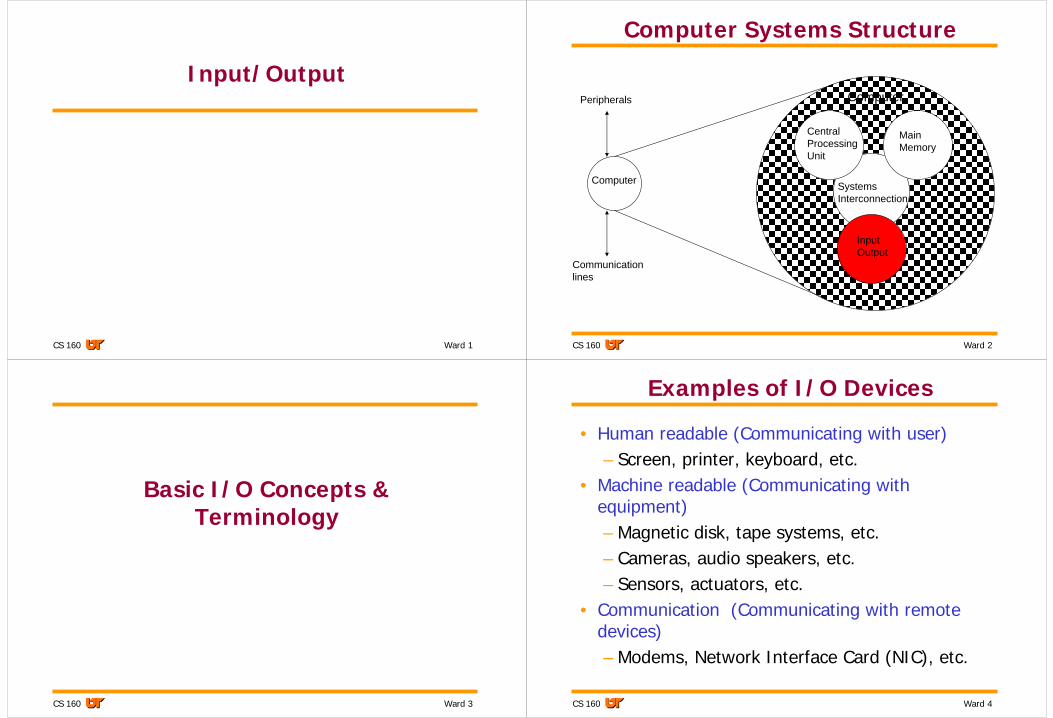
Computer Systems Structure
Computer
Main Memory
InputOutput
SystemsInterconnection
Peripherals
Communicationlines
CentralProcessing Unit
Computer
Ward 3CS 160
Basic I/O Concepts & Terminology
Ward 4CS 160
Examples of I/O Devices
• Human readable (Communicating with user)– Screen, printer, keyboard, etc.
• Machine readable (Communicating with equipment)– Magnetic disk, tape systems, etc.– Cameras, audio speakers, etc.– Sensors, actuators, etc.
• Communication (Communicating with remote devices)– Modems, Network Interface Card (NIC), etc.
Ward 5CS 160
Illustration of Early Devices
• Independent of processor– Separate circuitry & power
• Connected by digitals signals
Ward 6CS 160
Input/Output Problems
• Wide variety of peripherals– Delivering different amounts of data– At different speeds– In different formats
• All slower than CPU and RAM
Ward 7CS 160
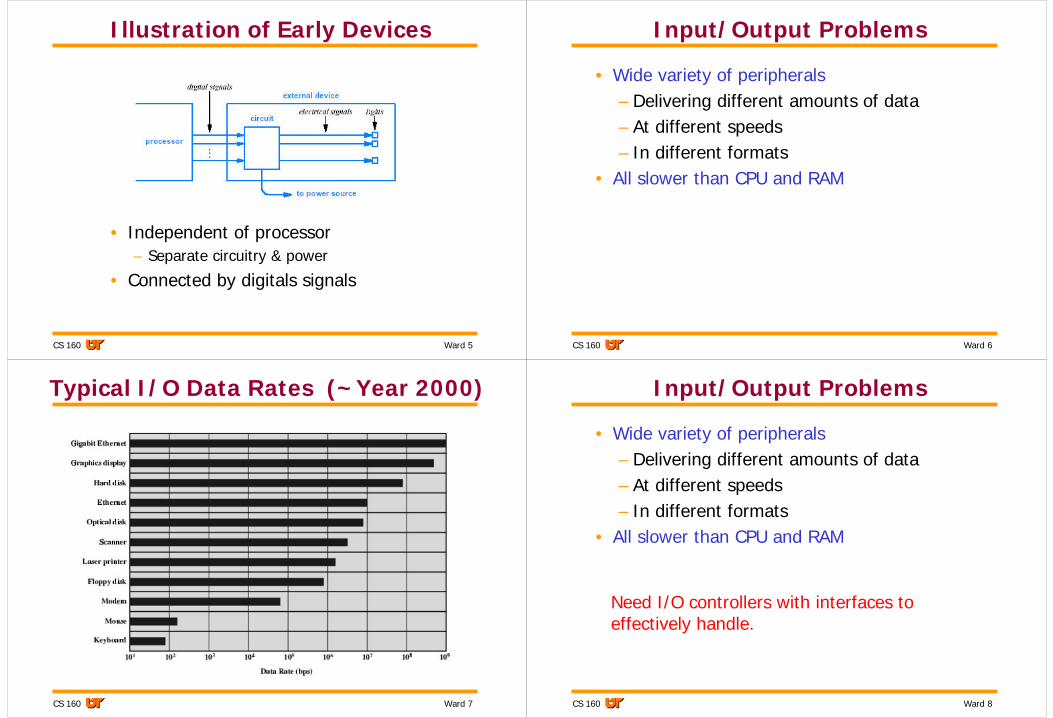
Typical I/O Data Rates (~Year 2000)
Ward 8CS 160
Input/Output Problems
• Wide variety of peripherals– Delivering different amounts of data– At different speeds– In different formats
• All slower than CPU and RAM
Need I/O controllers with interfaces to effectively handle.
Ward 9CS 160
Illustration of Modern Interface Controller
• Needed at each end of a physical connection• Allows arbitrary voltage and signal on
connection
Ward 10CS 160
I/O Controller Functions
• Control & Timing• CPU Communication• Device Communication• Data Buffering• Error Detection
Ward 11CS 160
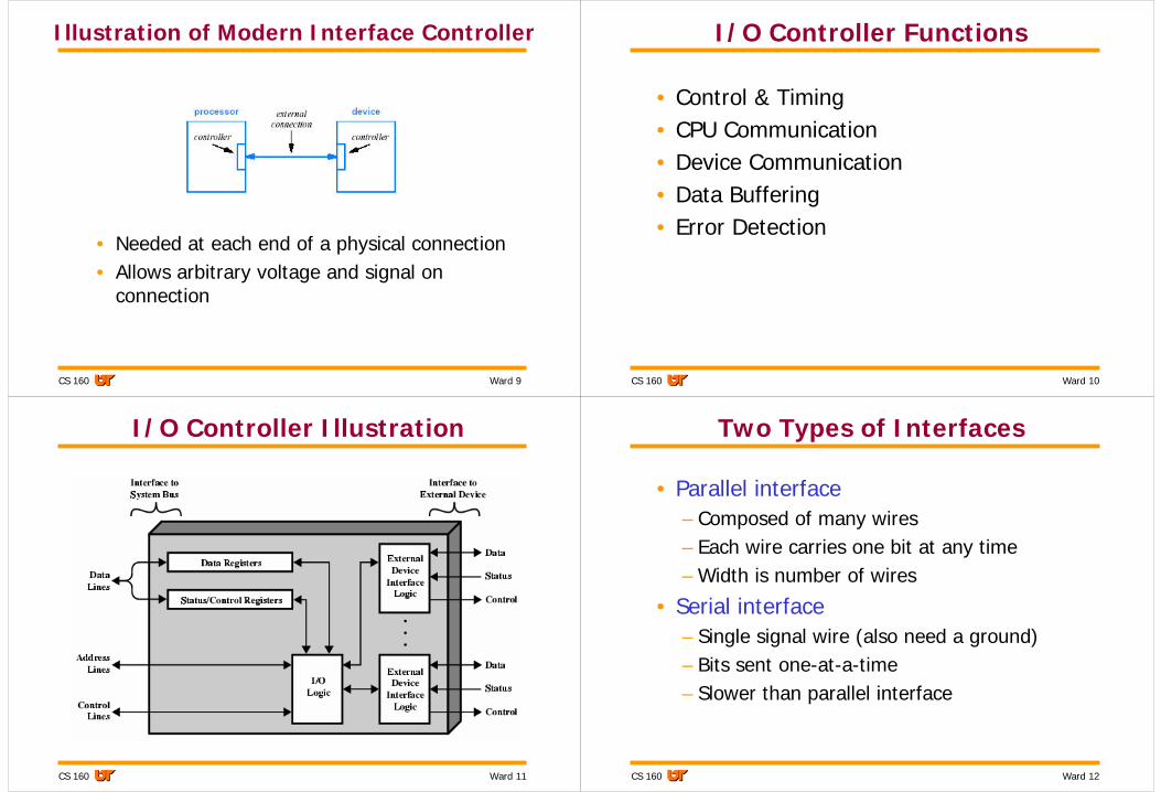
I/O Controller Illustration
Ward 12CS 160
Two Types of Interfaces
• Parallel interface– Composed of many wires– Each wire carries one bit at any time– Width is number of wires
• Serial interface– Single signal wire (also need a ground)– Bits sent one-at-a-time– Slower than parallel interface
Ward 13CS 160
Clock(s)
• Ends of connection typically use separate clocks, and controllers manage differences
• Transmission is self-clocking if signal encoded in such a way that receiving controller can determine boundary of bits
Ward 14CS 160
Duplex Technology
• Full-duplex– Simultaneous, bi-directional transfer– Example: disk drive supports simultaneous
read and write• Half-duplex
– Transfer in only one direction at a time– Interfaces must negotiate access before
transmitting
Ward 15CS 160
Latency and Throughput
• The latency of an interface is a measure of the time required to perform a single bit transfer
• The throughput of an interface is a measure of the data that can be transferred per unit time
Ward 16CS 160
Data Multiplexing
• Fundamental idea• Arises from hardware limits on parallelism
(pins or wires)• Allows sharing of hardware• Multiplexor
– Accepts input from many sources– Sends small amount from one source before
accepting another
• Demultiplexor– Receives transmission of pieces– Sends each piece to appropriate destination
Ward 17CS 160
Illustration of Mutiplexing
• 64 bits of data multiplexed over 16-bit path
Ward 18CS 160
Multiplexing and I/O Interfaces
• Multiplexing is used to construct an I/O interface that can transfer arbitraryamounts of data over a fixed number of parallel wires
• Multiplexing hardware divides the data into blocks, and transfers each block independently
Ward 19CS 160
Multiple Devices per External Interface
• Cannot afford separate interface per device– Too many wires– Not enough pins on processor chip
• Example – I/O devices, memory, etc. sharing a
common bus.
Ward 20CS 160
Processor View of I/O
• Processor does not access external devices directly
• Instead, processor uses a programming interface to pass requests to an interface controller
• Programming interface translates the requests into the appropriate external signals
Ward 21CS 160
Buses & Bus Architectures
Ward 22CS 160
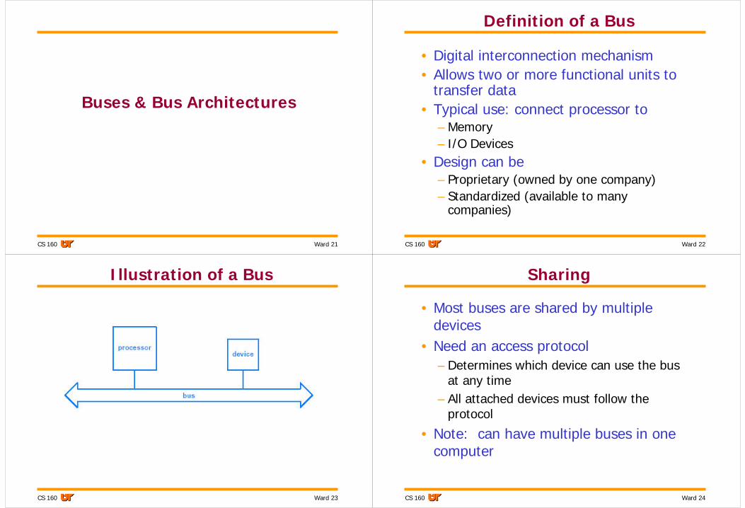
Definition of a Bus
• Digital interconnection mechanism• Allows two or more functional units to
transfer data• Typical use: connect processor to
– Memory– I/O Devices
• Design can be– Proprietary (owned by one company)– Standardized (available to many
companies)
Ward 23CS 160
Illustration of a Bus
Ward 24CS 160
Sharing
• Most buses are shared by multiple devices
• Need an access protocol– Determines which device can use the bus
at any time– All attached devices must follow the
protocol
• Note: can have multiple buses in one computer
Ward 25CS 160
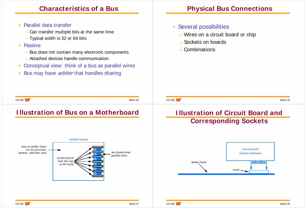
Characteristics of a Bus
• Parallel data transfer– Can transfer multiple bits at the same time– Typical width is 32 or 64 bits
• Passive– Bus does not contain many electronic components– Attached devices handle communication
• Conceptual view: think of a bus as parallel wires• Bus may have arbiter that handles sharing
Ward 26CS 160
Physical Bus Connections
• Several possibilities– Wires on a circuit board or chip– Sockets on boards– Combinations
Ward 27CS 160
Illustration of Bus on a Motherboard
Ward 28CS 160
Illustration of Circuit Board and Corresponding Sockets
Ward 29CS 160
Bus Interface
• Nontrivial• Controller circuit required
Ward 30CS 160
Conceptual Design of a Bus
• Need three functions– Control– Address specification– Data being transferred
• Conceptually three separate groups of wires (lines)
Ward 31CS 160
Illustration of Lines in a Bus
Ward 32CS 160
Bus Access
• Bus only supports two operations– fetch (also called read)– store (also called write)
• Access paradigm known as fetch-store paradigm
• Obvious for memory access• Surprise: all operations, including I/O,
must be performed using fetch-store paradigm
Ward 33CS 160
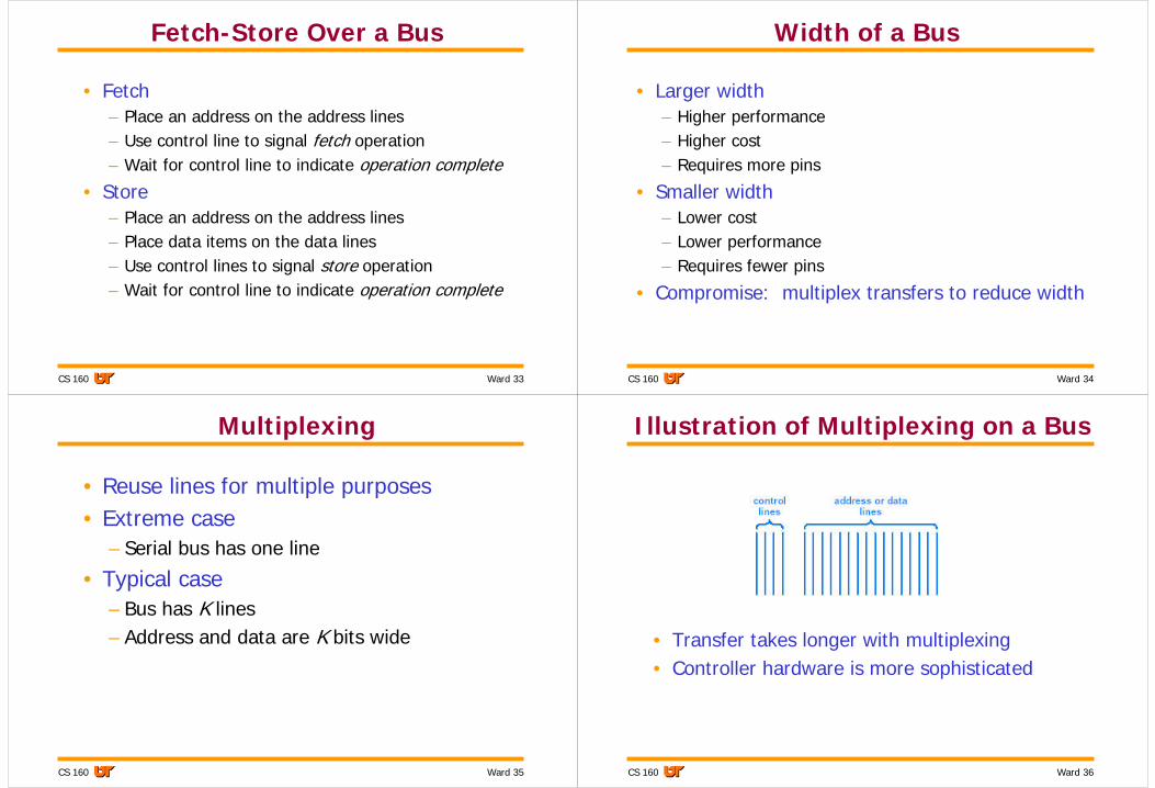
Fetch-Store Over a Bus
• Fetch– Place an address on the address lines– Use control line to signal fetch operation– Wait for control line to indicate operation complete
• Store– Place an address on the address lines– Place data items on the data lines– Use control lines to signal store operation– Wait for control line to indicate operation complete
Ward 34CS 160
Width of a Bus
• Larger width– Higher performance– Higher cost– Requires more pins
• Typical case– Bus has K lines– Address and data are K bits wide
Ward 36CS 160
Illustration of Multiplexing on a Bus
• Transfer takes longer with multiplexing• Controller hardware is more sophisticated
Ward 37CS 160
Effect of Bus Multiplexing on Design
• Addresses and data are multiplexed over a bus
• To optimize performance of the hardware, an architect chooses a single size for both data items and addresses
Ward 38CS 160
Illustration of Memory Bus
• Address over bus used to activate desired memory unit
Ward 39CS 160
Control Hardware and Addresses
• Although all interfaces receive all requests that pass across the bus, an interface only responds to requests that contain an address for which the interface has been configured
Ward 40CS 160
Steps an Interface Takes
Let R be the range of addresses assigned to the memory
Repeat forever {Monitor the bus until a request appears;if (the request specifies an address in R) {
respond to the request} else {
ignore the request }
}
Ward 41CS 160
Potential Errors on a Bus
• Address conflict– Two devices attempt to respond to a given
address
• Unassigned address– No device responds to a given address
Bus hardware reports a bus error.
Ward 42CS 160
Address Configuration and Sockets
• Two options for address configuration– Configure each interface with the set of
addresses– Arrange sockets so that wiring limits each
socket to a range of addresses• Latter avoids misconfiguration: owner can
plug in additional boards without configuring the hardware
• Note: some systems allow MMU to detect and configure boards automatically
Ward 43CS 160
Using Fetch-Store with Devices
• Example– Imaginary status light controller– Connected to 32-bit bus– Contains N separate lights– Desired functions are
• Turn display on• Turn display off• Set display brightness• Turn status light i on or off
Ward 44CS 160
Example: Meaning Assigned to Addresses
Low order sixteen bits of data value each controls a status light, where zero sets the corresponding light off and one sets it on
store108-111
Change brightness. Low-order four bits of the data value specify brightness value from zero (dim) through sixteen (bright)
store104-107
Returns zero if display is currently off, and nonzero if display is currently onfetch100-103
Nonzero data value turns the display on, and a zero data value turns the display off
store100-103
MeaningOperationAddress
Ward 45CS 160
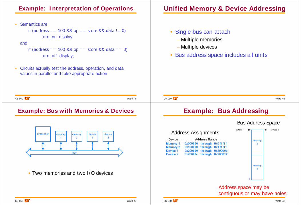
Example: Interpretation of Operations
• Semantics areif (address == 100 && op == store && data != 0)
turn_on_display;and
if (address == 100 && op == store && data == 0)turn_off_display;
• Circuits actually test the address, operation, and data values in parallel and take appropriate action
Ward 46CS 160
Unified Memory & Device Addressing
• Single bus can attach– Multiple memories– Multiple devices
• Bus address space includes all units
Ward 47CS 160
Example: Bus with Memories & Devices
• Two memories and two I/O devices
Ward 48CS 160
Example: Bus Addressing
Address Assignments
Bus Address Space
Address space may be contiguous or may have holes
Ward 49CS 160
Address Map• Specifies types of hardware
that can be used for different addresses
• Part of bus specification• Example on the right
– 16-bit bus– Bus can support up to 32,768
bytes• In a typical computer, the
part of the address space available to devices is sparsely populated – only a small percentage of address are used.
Ward 50CS 160
Bridge Connecting Two Buses
• An interconnection device• Maps range of addresses• Forwards operations and replies from one bus
to the other• Especially useful for adding an auxiliary bus
Ward 51CS 160
Bridge Address Mapping
Ward 52CS 160
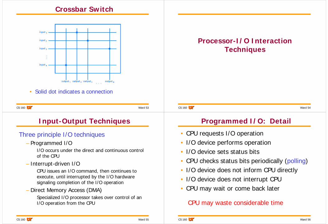
Switching Fabric• Alternative to bus
– Bus• only one pair of attached units can communicate at any given
time• Process: (1) obtain exclusive use of bus, (2) transfer data, and
(3) release bus
• Switching fabric connects multiple devices– Allows multiple attached units to communicate
simultaneously
• Sender supplies data and destination device• Fabric delivers data to specified destination
Ward 53CS 160
Crossbar Switch
• Solid dot indicates a connection
Ward 54CS 160
Processor-I/O Interaction Techniques
Ward 55CS 160
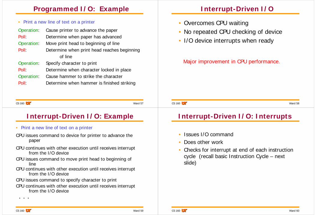
Input-Output Techniques
Three principle I/O techniques– Programmed I/O
I/O occurs under the direct and continuous control of the CPU
– Interrupt-driven I/OCPU issues an I/O command, then continues to execute, until interrupted by the I/O hardware signaling completion of the I/O operation
– Direct Memory Access (DMA)Specialized I/O processor takes over control of an I/O operation from the CPU
Ward 56CS 160
Programmed I/O: Detail
• CPU requests I/O operation• I/O device performs operation• I/O device sets status bits• CPU checks status bits periodically (polling)• I/O device does not inform CPU directly• I/O device does not interrupt CPU• CPU may wait or come back later
CPU may waste considerable time
Ward 57CS 160
Programmed I/O: Example
• Print a new line of text on a printer
Operation: Cause printer to advance the paperPoll: Determine when paper has advancedOperation: Move print head to beginning of linePoll: Determine when print head reaches beginning
of lineOperation: Specify character to printPoll: Determine when character locked in placeOperation: Cause hammer to strike the characterPoll: Determine when hammer is finished striking
Ward 58CS 160
Interrupt-Driven I/O
• Overcomes CPU waiting• No repeated CPU checking of device• I/O device interrupts when ready
Major improvement in CPU performance.
Ward 59CS 160
Interrupt-Driven I/O: Example• Print a new line of text on a printer
CPU issues command to device for printer to advance the paper
CPU continues with other execution until receives interrupt from the I/O device
CPU issues command to move print head to beginning of line
CPU continues with other execution until receives interrupt from the I/O device
CPU issues command to specify character to printCPU continues with other execution until receives interrupt
from the I/O device. . .
Ward 60CS 160
Interrupt-Driven I/O: Interrupts
• Issues I/O command• Does other work• Checks for interrupt at end of each instruction
cycle (recall basic Instruction Cycle – next slide)
Ward 61CS 160
Basic Instruction Cycle States
Ward 62CS 160
Handling an Interrupt
• Save the current execution state– Values in registers– Program counter– Condition code
• Determine which device issued the interrupt• Call the procedure that handles the device
– Runs code for the specific interrupt (e.g., fetch & store)• Clear the interrupt signal from the bus• Restore the current execution state
Ward 63CS 160
Direct Memory Access
• Interrupt driven and programmed I/O require active CPU intervention– Transfer rate is limited
• CPU saves process state information– CPU is tied up
DMA is the solution.
Ward 64CS 160
DMA Operation
• CPU tells DMA controller:– Read/Write– Device address– Starting address of memory block for data– Amount of data to be transferred
• CPU carries on with other work• DMA controller has necessary digital logic to
deal with transfer• DMA controller sends interrupt when finished
Ward 65CS 160
DMA Transfer
• DMA controller requests bus– Bus must allow multiple units to access the bus
without interference• When control of bus given, DMA controller
begins transfer of data• CPU can request bus for its operations and is
given higher priority• Slows down CPU but not as much as CPU
doing transfer
Ward 66CS 160
Effect of Cache
• What effect does a system with caching memory have on DMA?– Cache reduces the number of memory
accesses, thus bus is available more often for DMA use
Ward 67CS 160
DMA Configurations [1]
• Single Bus, Detached DMA controller• Each transfer uses bus twice
– I/O to DMA then DMA to memory• Twice the potential interference with the CPU
Ward 68CS 160
DMA Configurations [2]
• Single Bus, Integrated DMA controller• Controller may support >1 device• Each transfer uses bus once
– DMA to memory
Ward 69CS 160
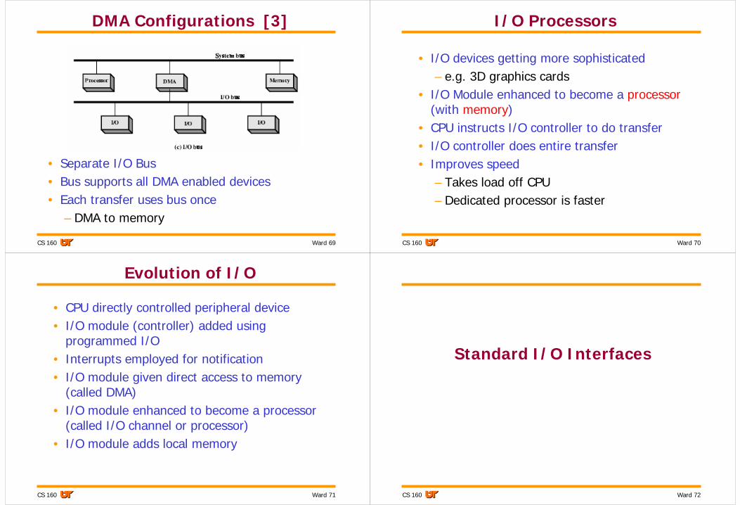
DMA Configurations [3]
• Separate I/O Bus• Bus supports all DMA enabled devices• Each transfer uses bus once
– DMA to memory
Ward 70CS 160
I/O Processors
• I/O devices getting more sophisticated– e.g. 3D graphics cards
• I/O Module enhanced to become a processor(with memory)
• CPU instructs I/O controller to do transfer• I/O controller does entire transfer• Improves speed
– Takes load off CPU– Dedicated processor is faster
Ward 71CS 160
Evolution of I/O
• CPU directly controlled peripheral device• I/O module (controller) added using
programmed I/O• Interrupts employed for notification• I/O module given direct access to memory
(called DMA)• I/O module enhanced to become a processor
(called I/O channel or processor)• I/O module adds local memory
Ward 72CS 160
Standard I/O Interfaces
Ward 73CS 160
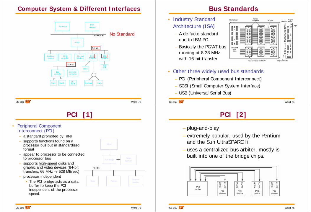
Computer System & Different Interfaces
No Standard
Ward 74CS 160
Bus Standards• Industry Standard
Architecture (ISA)– A de facto standard
due to IBM PC
– Basically the PC/AT bus running at 8.33 MHz with 16-bit transfer
• Other three widely used bus standards:– PCI (Peripheral Component Interconnect)
– SCSI (Small Computer System Interface)
– USB (Universal Serial Bus)
Ward 75CS 160
PCI [1]• Peripheral Component
Interconnect (PCI)– a standard promoted by Intel– supports functions found on a
processor bus but in standardized format
– appear to processor to be connected to processor bus
– supports high-speed disks and graphic and video devices (64-bit transfers, 66 MHz → 528 MB/sec)
– processor independent• The PCI bridge acts as a data
buffer to keep the PCI independent of the processor speed.
memory
Host
PCI bridge
EthernetPrinterDisk interface
PCI bus
Main
Ward 76CS 160
PCI [2]
– plug-and-play – extremely popular, used by the Pentium
and the Sun UltraSPARC Iii– uses a centralized bus arbiter, mostly is
built into one of the bridge chips.
Ward 77CS 160
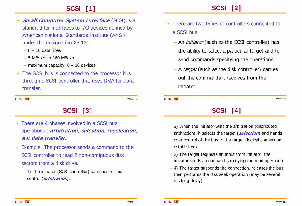
SCSI [1]
• Small Computer System Interface (SCSI) is a standard for interfaces to I/O devices defined by American National Standards Institute (ANSI) under the designation X3.131.– 8 – 16 data lines
– 5 MB/sec to 160 MB/sec
– maximum capacity: 8 – 16 devices
• The SCSI bus is connected to the processor bus through a SCSI controller that uses DMA for data transfer.
Ward 78CS 160
SCSI [2]
• There are two types of controllers connected to
a SCSI bus.
– An initiator (such as the SCSI controller) has
the ability to select a particular target and to
send commands specifying the operations.
– A target (such as the disk controller) carries
out the commands it receives from the
initiator.
Ward 79CS 160
SCSI [3]
• There are 4 phases involved in a SCSI bus operations : arbitration, selection, reselection, and data transfer.
• Example: The processor sends a command to the
SCSI controller to read 2 non-contiguous disk
sectors from a disk drive.
– 1) The initiator (SCSI controller) contends for bus
control (arbitration).
Ward 80CS 160
SCSI [4]
– 2) When the initiator wins the arbitration (distributed
arbitration), it selects the target (selection) and hands
over control of the bus to the target (logical connection
established).
– 3) The target requests an input from initiator; the initiator sends a command specifying the read operation.
– 4) The target suspends the connection, releases the bus; then performs the disk seek operation (may be several ms long delay).
Ward 81CS 160
SCSI [5]
– 5) The target sends a seek command to the disk drive
to read the first sector; then requests control of the bus;
wins the arbitration; then reselects the initiator to
restore the connection (reselection).
– 6) The target transfers the first sector to the initiator
(data transfer), then suspends the connection again.
– 7) The target sends a seek command to the disk drive
to read the second sector, then transfers it to the
initiator as before. The logical connection is then
terminated.
Ward 82CS 160
SCSI [6]
• The data transfers are always controlled by the target controller.
• While a particular connection is suspended, other devices can use the bus. This ability to overlap data transfer requests leads to its high performance.
Ward 83CS 160
USB [1]
• The Universal Serial Bus (USB)– developed by collaborative efforts of computer and
communications companies, including Compaq, Hewlett-Packard, Intel, Lucent, Microsoft, Nortel Networks, and Philips
– provide a simple, low-cost, and easy to use interconnection system
– accommodate a wide range of data transfer characteristics for I/O devices, including Internet connections (low-speed: 1.5Mbits/s, full-speed: 12Mbits/s, high-speed: 480Mbits/s (USB 2.0))
Ward 84CS 160
USB [2]
– plug-and-play• when a new I/O device is plugged in, the root hub
detects this event and interrupts the OS
• The OS queries the device to find out what it is and how much USB bandwidth it needs
• If the OS decides that there is enough bandwidth, it assigns the new device a unique address and downloads this address and other information to configuration registers inside the device
Ward 85CS 160
Host computer
Roothub
Hub
I/Odevice
Hub I/Odevice
I/Odevice
Hub
I/Odevice
I/Odevice
I/Odevice
USB [3]
• A USB system consists of aroot hub that usually plugs into the main bus; the root hub can be connected to I/O devices or to expansion hubs –a tree topology.
• A message sent by the host computer is broadcast to all I/O devices.
• A message from an I/O device is sent only upstream towards the root of the tree.
• USB has its own 7-bit address space
Ward 86CS 160
Architecture of a Typical Pentium II System
Bridge is used to translate the signals and protocols of one bus into


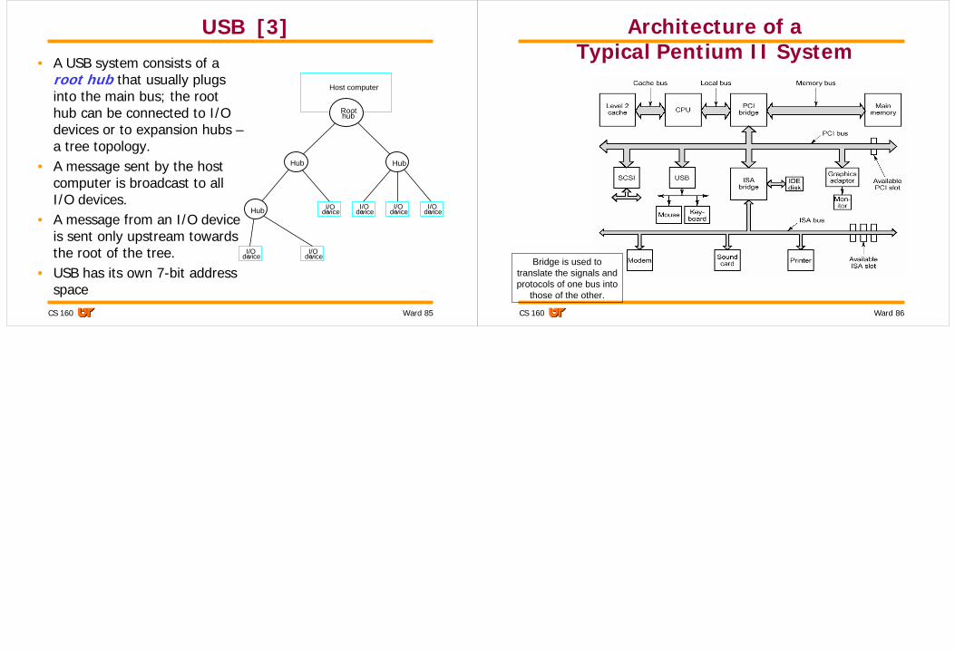


![T2.1 [Computer Component- Input Output Device]](https://static.documents.pub/doc/80x56/577cde301a28ab9e78ae937d/t21-computer-component-input-output-device.jpg)


