209


COMPUTER TESTING SUPPLEMENTFOR
INSTRUMENT RATING
2005
U.S. DEPARTMENT OF TRANSPORTATIONFEDERAL AVIATION ADMINISTRATION
Flight Standards Service
CT-8080-3E FrontPages 04/18/2005, 4:52 PM1

CT-8080-3E FrontPages 04/18/2005, 4:52 PM2
PREFACE
This computer testing supplement is designed by the Flight Standards Service of the Federal Aviation Administration(FAA) for use by computer testing designees (CTDs) and testing centers in the administration of airman knowledge testsin the following knowledge areas:
Instrument Rating—Airplane (IRA)Instrument Rating—Rotorcraft/Helicopter (IRH)Instrument Rating—Powered Lift (IPL)Instrument Flight Instructor—Powered Lift (IPI)Instrument Rating—Foreign Pilot (IFP)Instrument Flight Instructor—Airplane (FII)Instrument Flight Instructor—Rotorcraft/Helicopter - (FIH)Instrument Flight Instructor—Airplane (added rating) (AIF)Instrument Flight Instructor—Rotorcraft/Helicopter (added rating) (HIF)Ground Instructor—Instrument (IGI)
FAA-CT-8080-3E supercedes FAA-CT-8080-3D, Computer Testing Supplement for Instrument Rating, dated 2000.
Comments regarding this supplement should be sent to:
U.S. Department of TransportationFederal Aviation AdministrationFlight Standards ServiceAirman Testing Standards Branch, AFS-630P.O. Box 25082Oklahoma City, OK 73125
iii
CT-8080-3E FrontPages 04/18/2005, 4:52 PM3

CT-8080-3E FrontPages 04/18/2005, 4:52 PM4

v
Preface ................................................................................................................................................................................. iiiContents .................................................................................................................................................................................v
APPENDIX 1
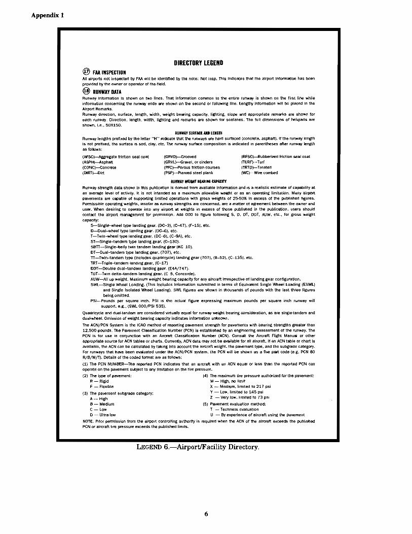
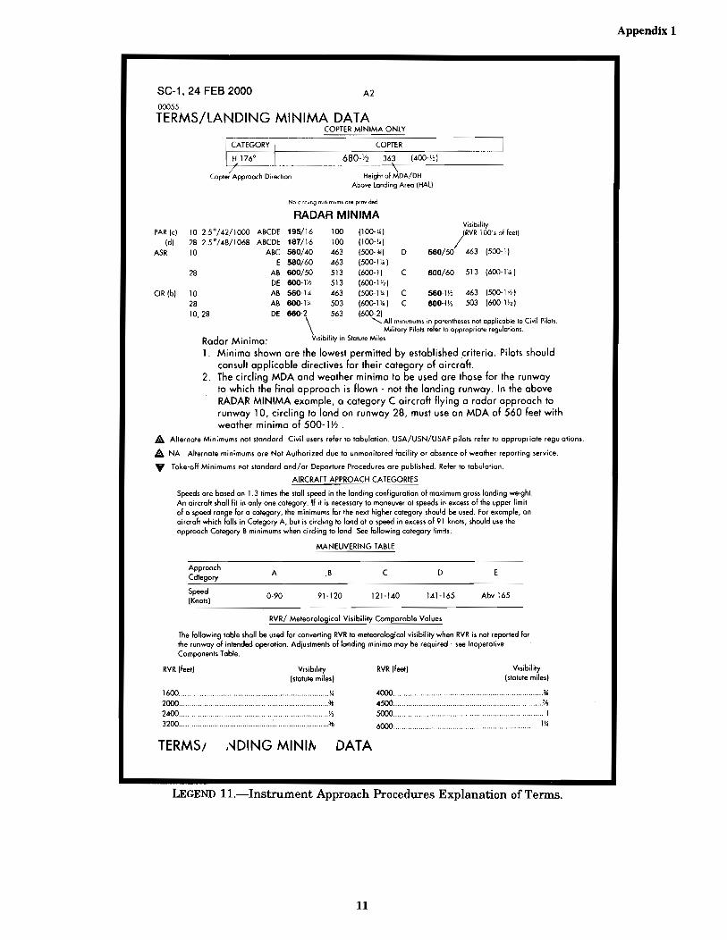
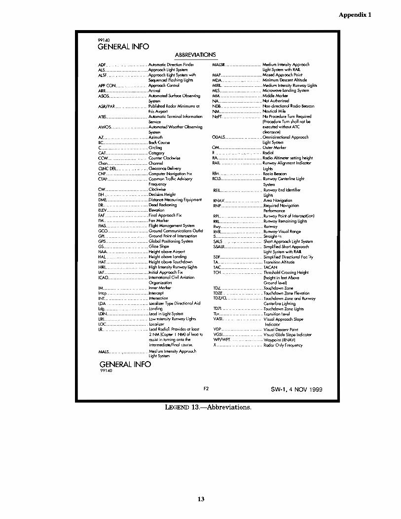
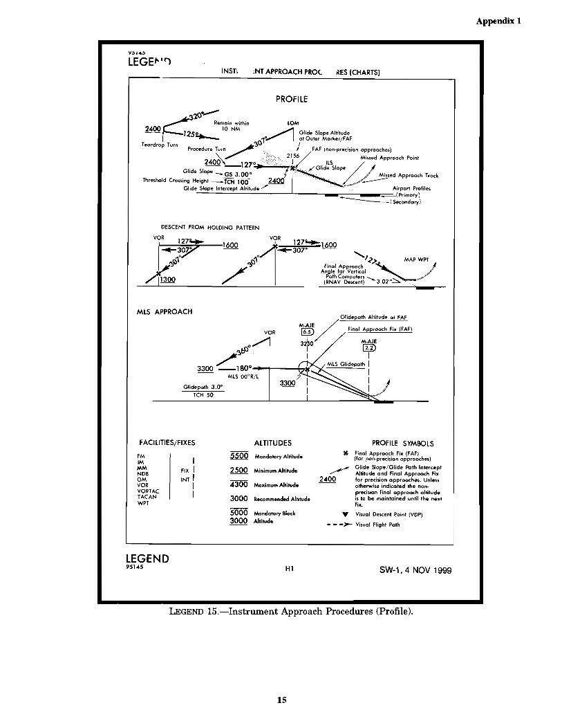
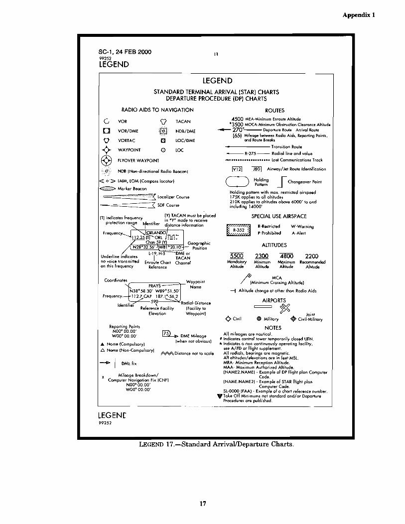
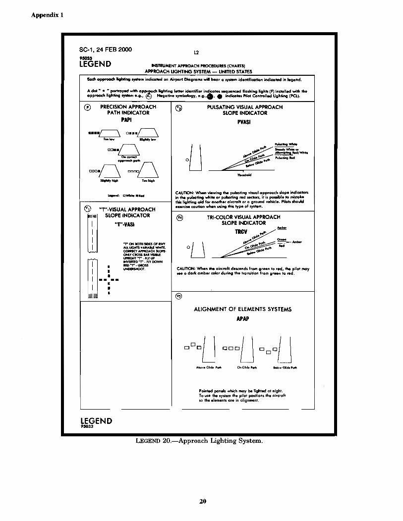
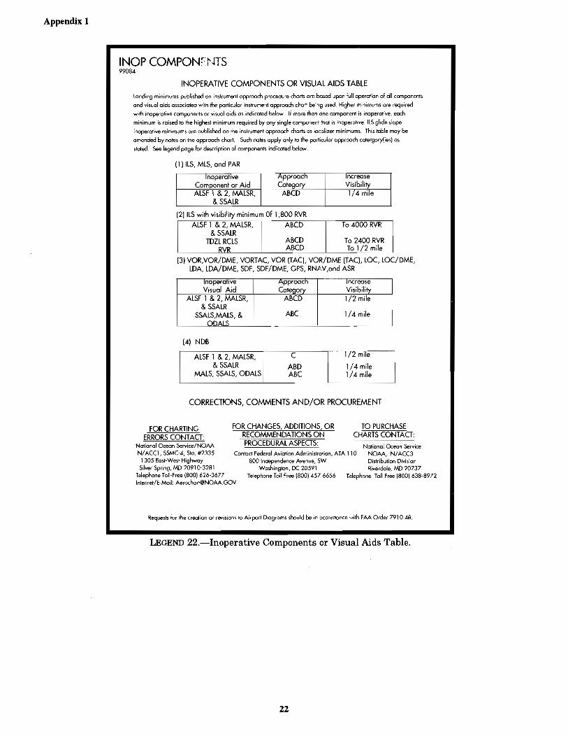
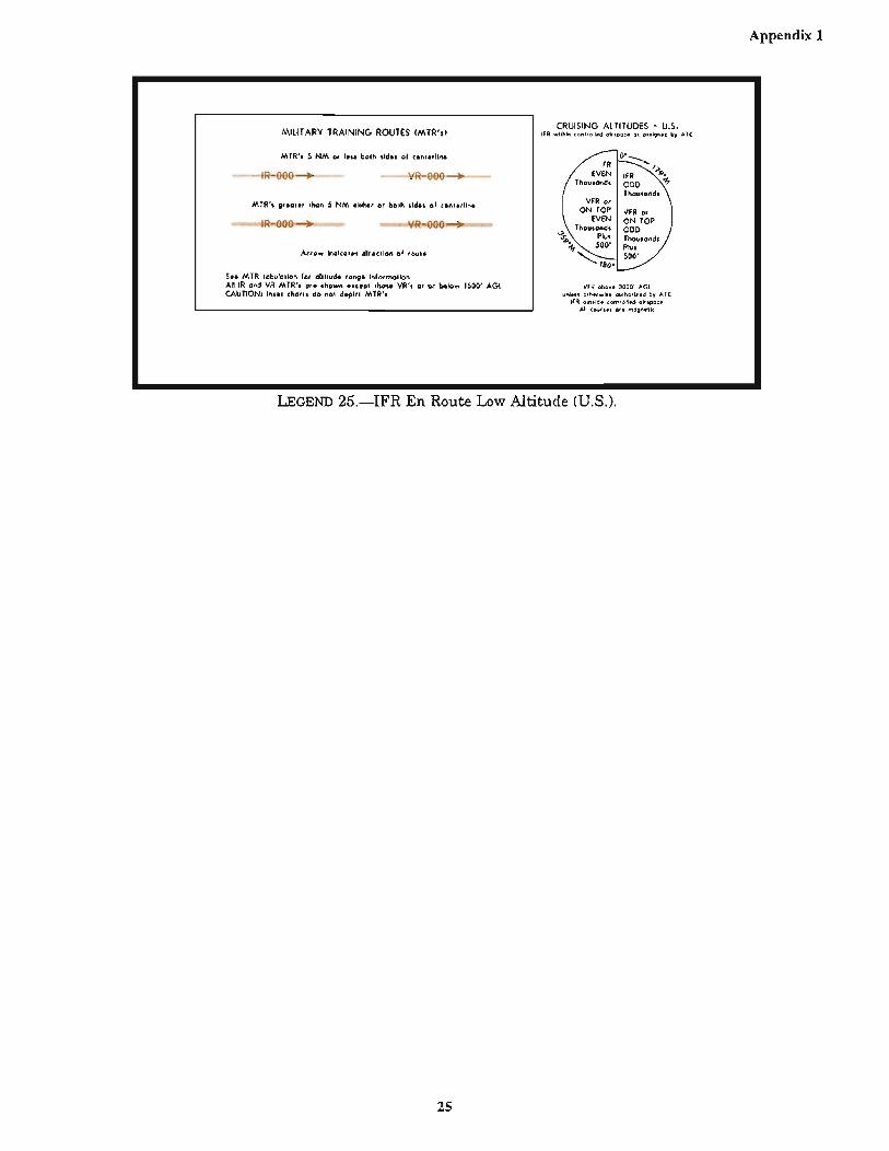
LEGEND 1.—Abbreviations ...................................................................................................................................................1LEGEND 2.—Airport/Facility Directory ................................................................................................................................2LEGEND 3.—Airport/Facility Directory ................................................................................................................................3LEGEND 4.—Airport/Facility Directory ................................................................................................................................4LEGEND 5.—Airport/Facility Directory ................................................................................................................................5LEGEND 6.—Airport/Facility Directory ................................................................................................................................6LEGEND 7.—Airport/Facility Directory ................................................................................................................................7LEGEND 8.—Airport/Facility Directory ................................................................................................................................8LEGEND 9.—Airport/Facility Directory ................................................................................................................................9LEGEND 10.—Instrument Approach Procedures Explanation of Terms .............................................................................10LEGEND 11.—Instrument Approach Procedures Explanation of Terms .............................................................................11LEGEND 12.—General Information .....................................................................................................................................12LEGEND 13.— Abbreviations ..............................................................................................................................................13LEGEND 14.—Instrument Approach Procedures (Symbols) ...............................................................................................14LEGEND 15.—Instrument Approach Procedures (Profile) ..................................................................................................15LEGEND 16.—Instrument Takeoff Procedure Charts, Rate-of-Climb Table .......................................................................16LEGEND 17.—Standard Arrival/Departure Charts ..............................................................................................................17LEGEND 18.—Airport Diagram ...........................................................................................................................................18LEGEND 19.—Approach Lighting Systems .........................................................................................................................19LEGEND 20.—Approach Lighting System ..........................................................................................................................20LEGEND 21.—Instrument Approach Procedure Charts, Rate-of-Descent Table .................................................................21LEGEND 22.—Inoperative Components or Visual Aids Table ............................................................................................22LEGEND 23.—IFR En Route Low Altitude (U.S.) ..............................................................................................................23LEGEND 24.—IFR En Route Low Altitude (U.S.) ..............................................................................................................24LEGEND 25.—IFR En Route Low Altitude (U.S.) ..............................................................................................................25LEGEND 26.—Aircraft Equipment Suffixes ........................................................................................................................26LEGEND 27.—Air Navigation Radio Aids ...........................................................................................................................27LEGEND 28.—ILS Standard Characteristics and Terminology ...........................................................................................28LEGEND 29.—Temperature Conversion Chart ....................................................................................................................29
PageCONTENTS
APPENDIX 2
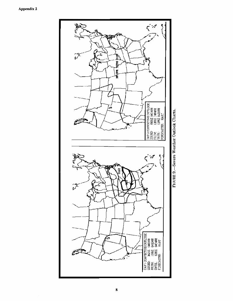
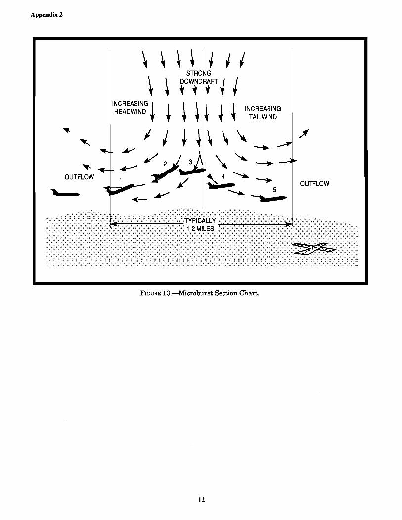
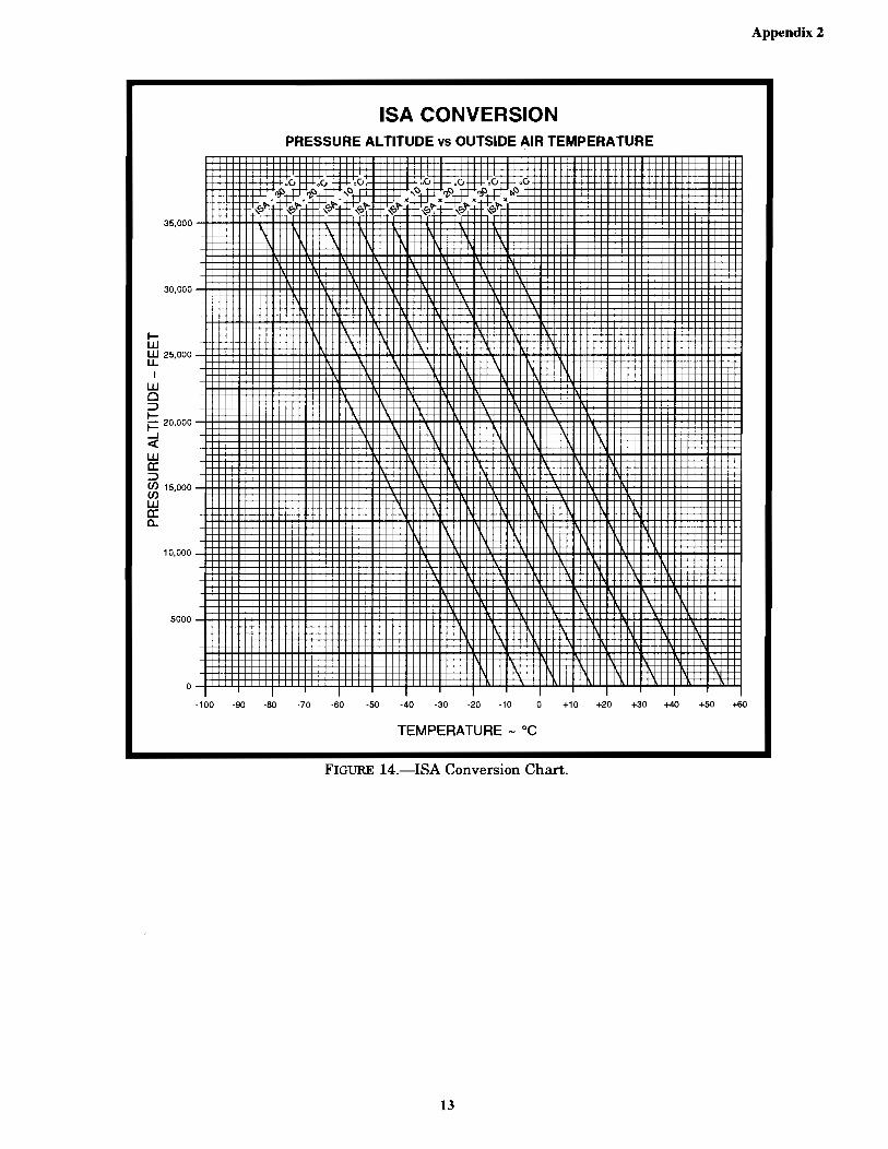
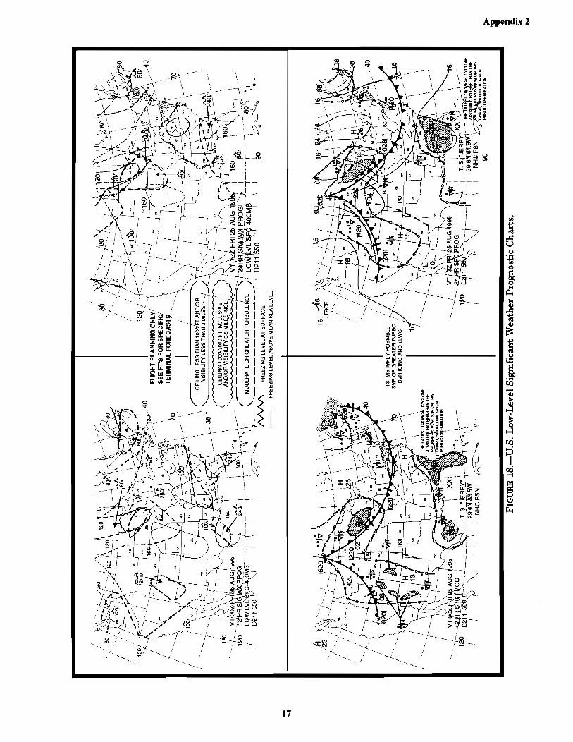
FIGURE 1.—Flight Plan .........................................................................................................................................................1FIGURE 2.—Winds and Temperatures Aloft Forecast ...........................................................................................................1FIGURE 3.—Standard Conversion Chart ................................................................................................................................2FIGURE 4.—Weather Depiction Chart ...................................................................................................................................3FIGURE 5.—Symbol Used on Low-Level Significant Weather Prognostic Chart .................................................................4FIGURE 6.—(Withdrawn) PAGE INTENTIONALLY LEFT BLANK ................................................................................5FIGURE 7.—High-Level Significant Weather Prognostic Chart ............................................................................................6FIGURE 8.—Radar Summary Chart .......................................................................................................................................7FIGURE 9.—Severe Weather Outlook Charts ........................................................................................................................8FIGURE 10.—Deleted .............................................................................................................................................................9FIGURE 11.—Deleted ...........................................................................................................................................................10FIGURE 12.—Observed Winds Aloft for 34,000 Feet .........................................................................................................11FIGURE 13.—Microburst Section Chart ..............................................................................................................................12FIGURE 14.—ISA Conversion Chart ....................................................................................................................................13FIGURE 15.—Deleted ...........................................................................................................................................................14FIGURE 16.—Deleted ...........................................................................................................................................................15FIGURE 17.—Deleted ...........................................................................................................................................................16FIGURE 18.—U.S. Low-Level Significant Weather Prognostic Charts ...............................................................................17
CT-8080-3E FrontPages 04/18/2005, 4:52 PM5

vi
Page
CONTENTS—Continued
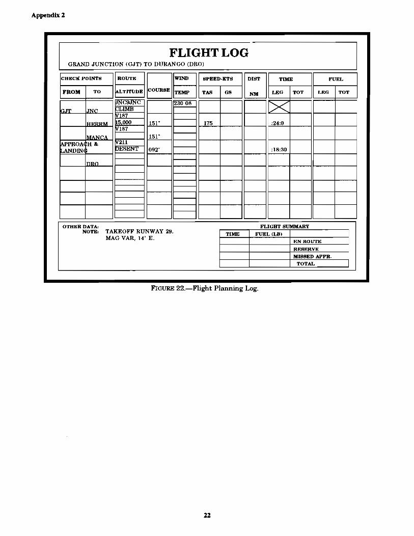
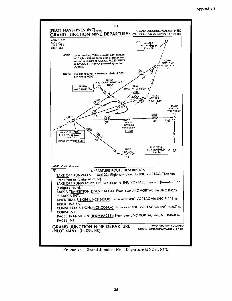
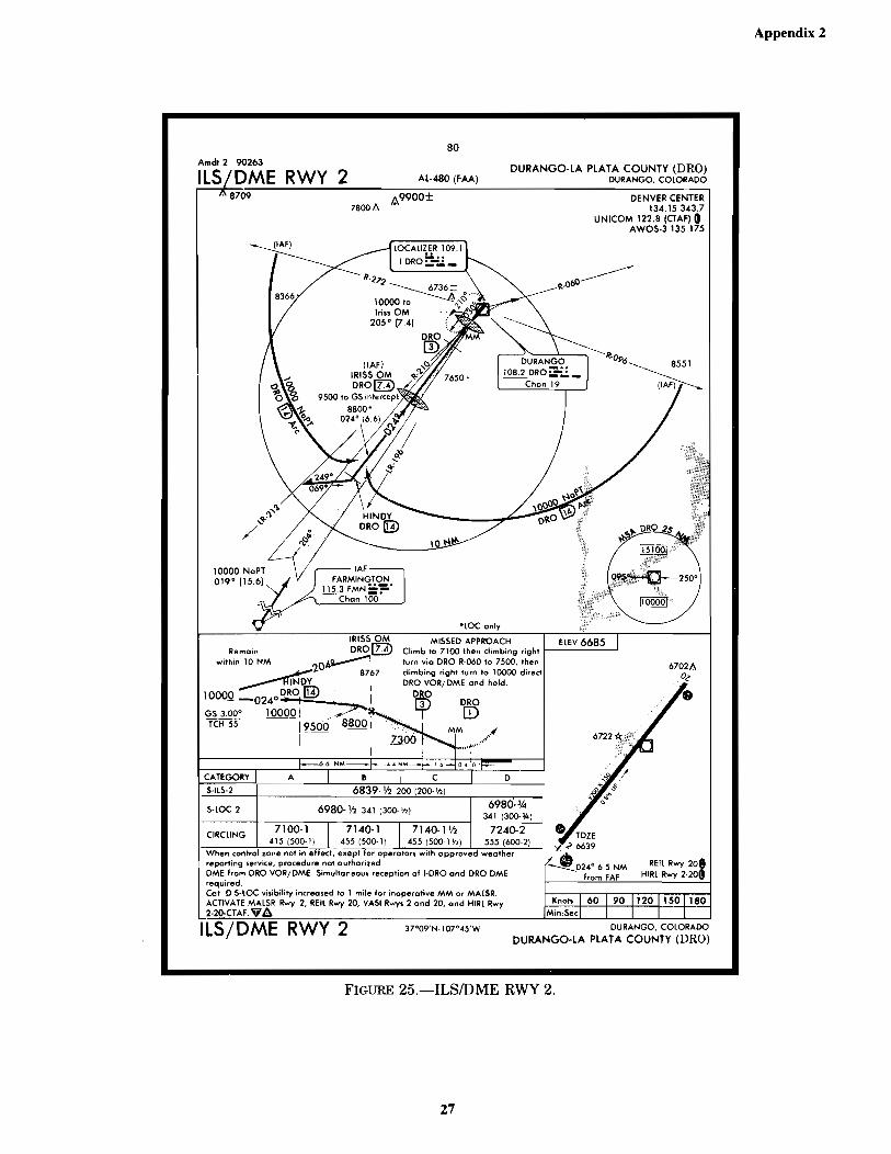
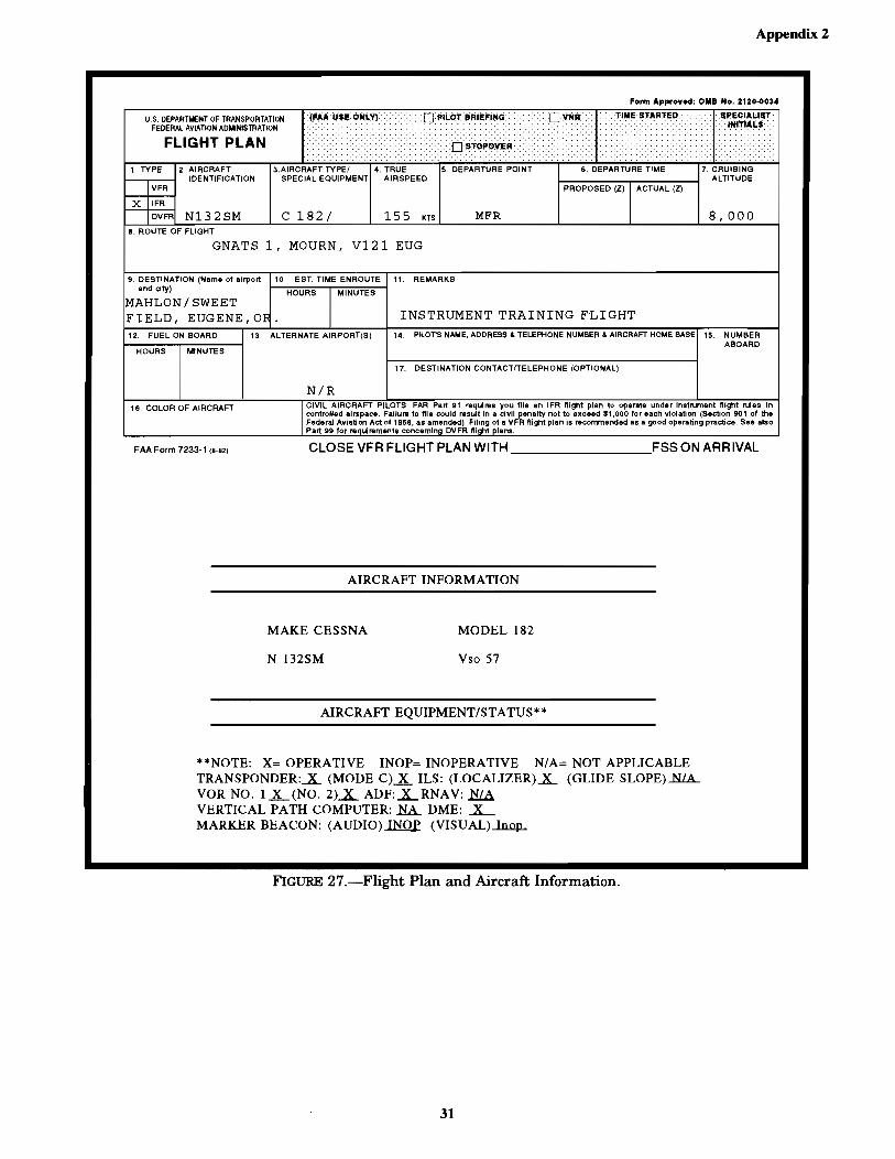
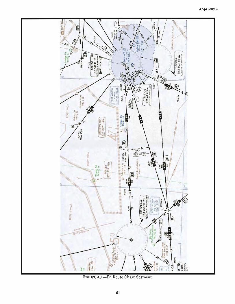
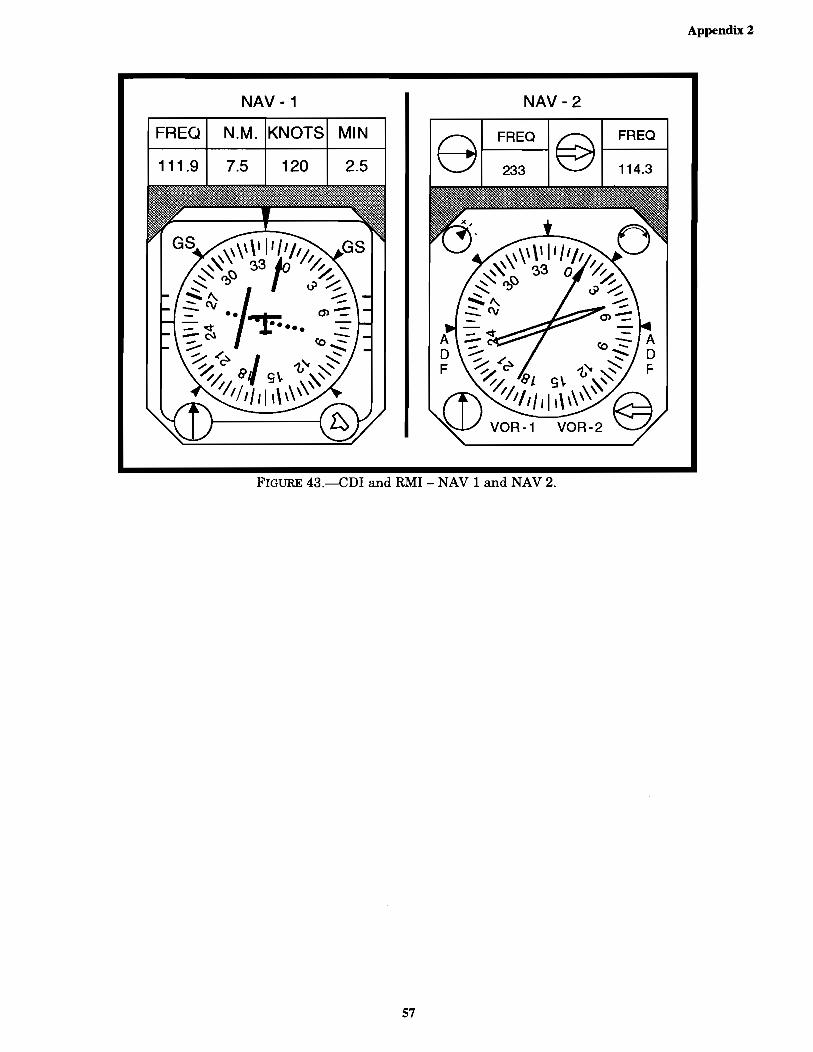
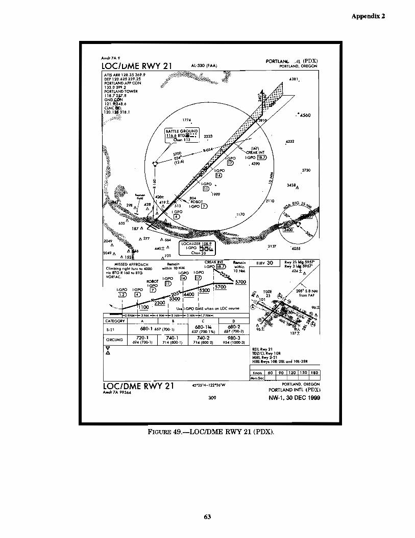
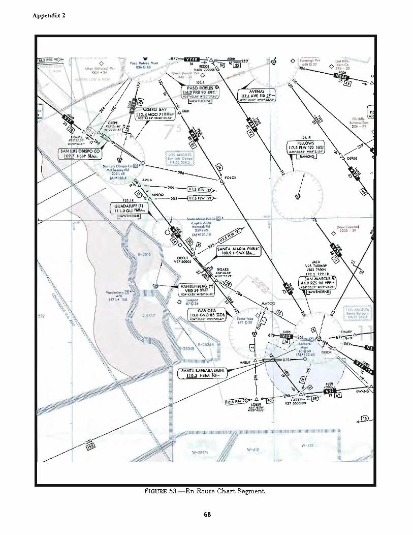
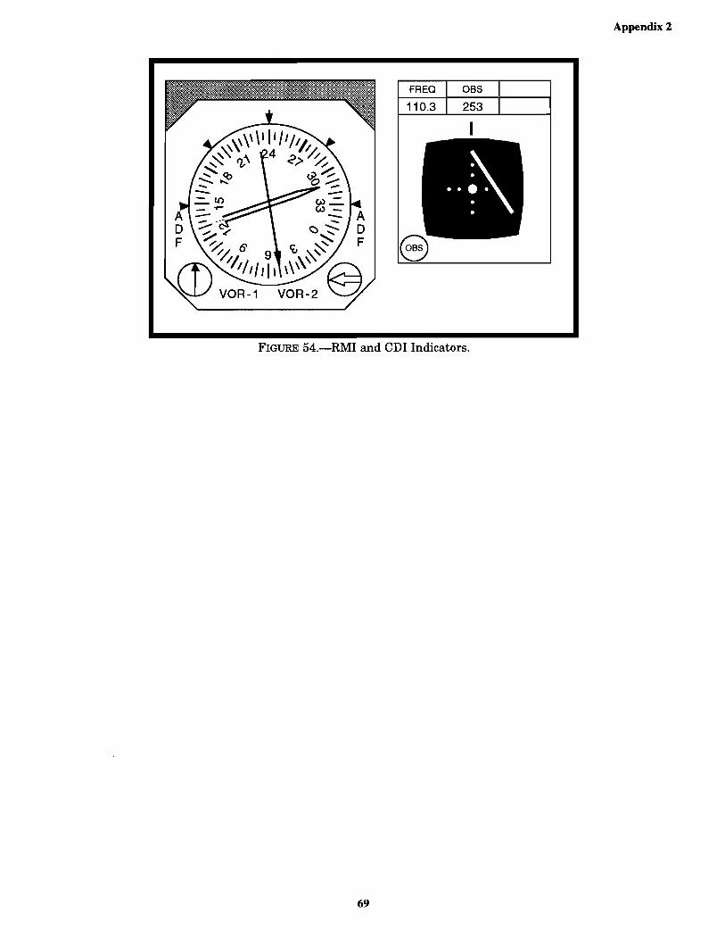
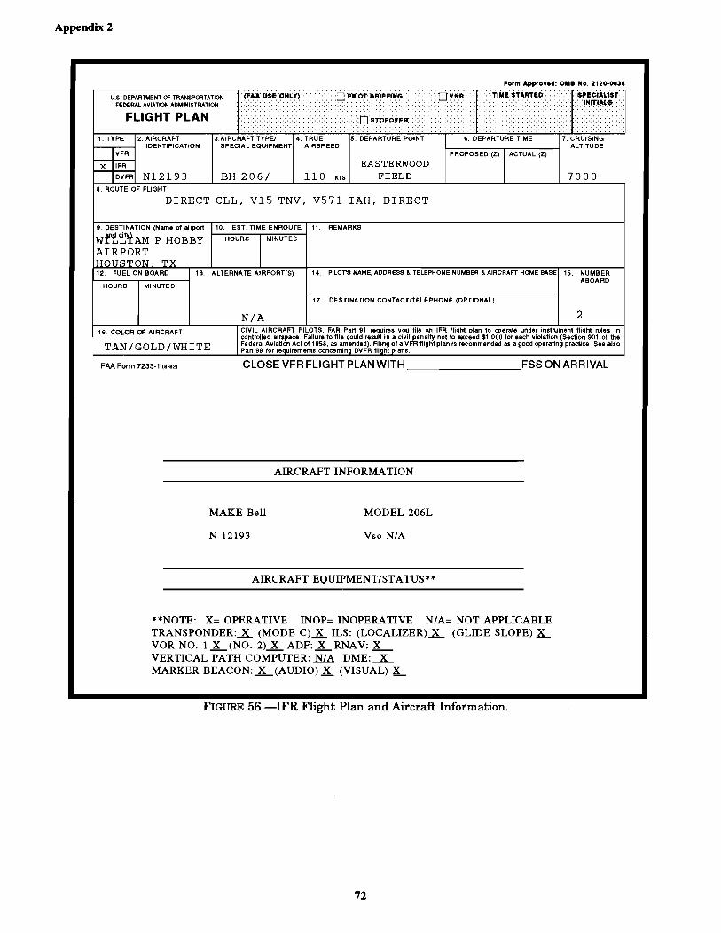
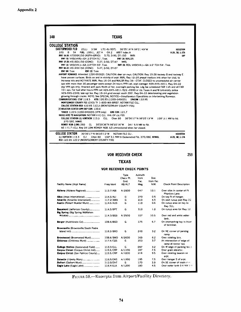
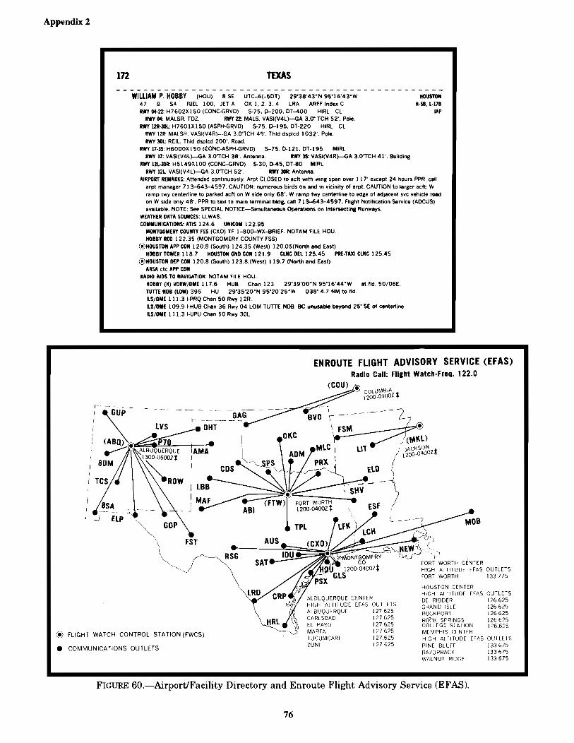
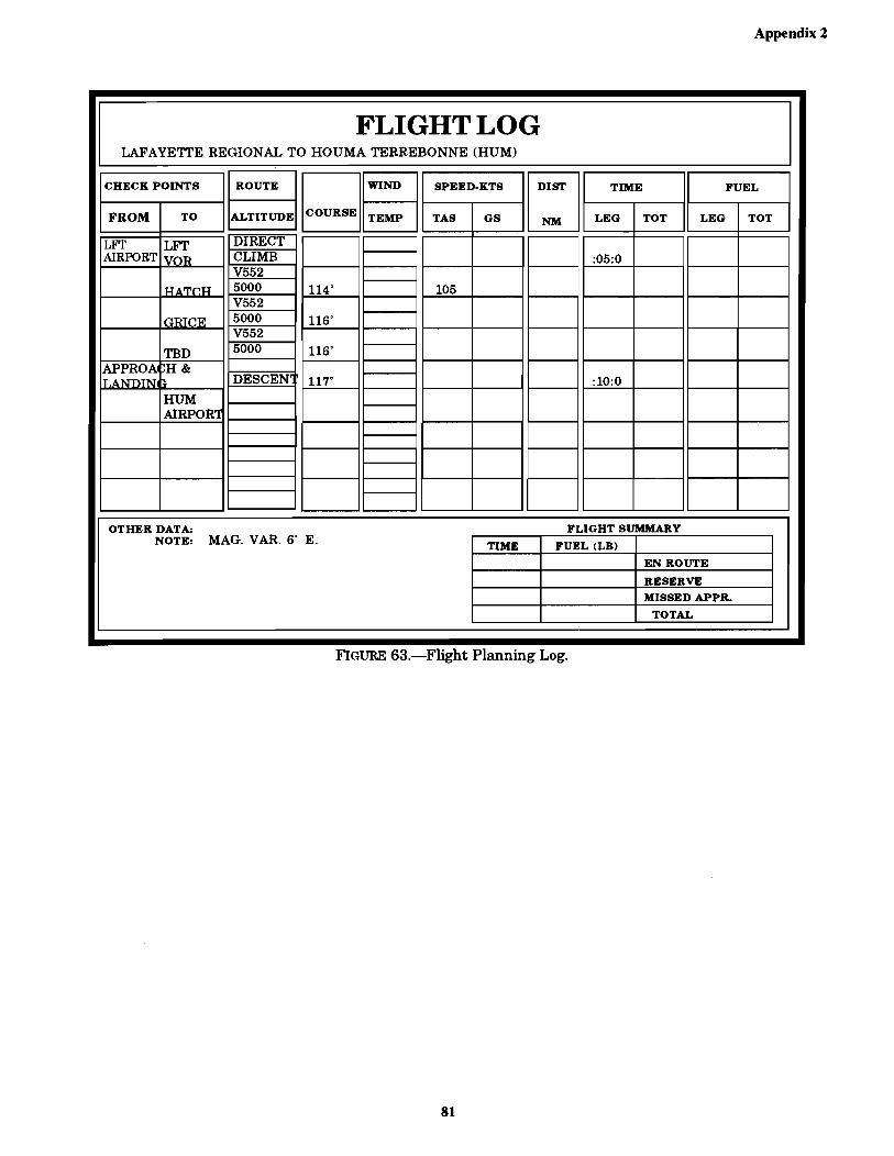
FIGURE 19.—Deleted ...........................................................................................................................................................18FIGURE 20.—High-Level Significant Weather Prognostic Chart ........................................................................................19FIGURE 21.—Flight Plan and Aircraft Information .............................................................................................................20FIGURE 21A.—Flight Plan and Aircraft Information ..........................................................................................................21FIGURE 22.—Flight Planning Log .......................................................................................................................................22FIGURE 22A.—Flight Planning Log ....................................................................................................................................23FIGURE 23.—Grand Junction Nine Departure (JNC9.JNC) ................................................................................................25FIGURE 24.—En Route Low-Altitude Chart Segment ........................................................................................................26FIGURE 25.—ILS/DME RWY 2 ..........................................................................................................................................27FIGURE 26.—ILS RWY 11 ..................................................................................................................................................29FIGURE 27.—Flight Plan and Aircraft Information .............................................................................................................31FIGURE 28.—Flight Planning Log .......................................................................................................................................32FIGURE 29.—ILS RWY 16 (EUG) and Excerpt from Airport/Facility Directory .............................................................33FIGURE 30.—GNATS One Departure and Excerpt from Airport/Facility Directory ..........................................................35FIGURE 30A.—RMI Indicator .............................................................................................................................................36FIGURE 31.—En Route Low-Altitude Chart Segment ........................................................................................................37FIGURE 32.—Flight Plan and Aircraft Information .............................................................................................................38FIGURE 33.—Flight Planning Log .......................................................................................................................................39FIGURE 34.—En Route Chart ..............................................................................................................................................40FIGURE 34A.—Airport/Facility Directory (HOT) ...............................................................................................................41FIGURE 35.—En Route Chart Segment and Blue Ridge Three Arrival ..............................................................................42FIGURE 35A.—Blue Ridge Three Arrival Description ........................................................................................................43FIGURE 36.—Excerpt from Airport/Facility Directory .......................................................................................................44FIGURE 36A.—RNAV RWY 33 (ADS) ..............................................................................................................................45FIGURE 37.—CDI and RMI – NAV 1 and NAV 2 ..............................................................................................................47FIGURE 38.—Flight Plan and Aircraft Information .............................................................................................................48FIGURE 39.—Flight Log and Excerpt from Airport/Facility Directory (21 XS) .................................................................49FIGURE 39A.—Excerpt from Airport/Facility Directory (21 XS) .......................................................................................50FIGURE 40.—En Route Chart Segment ...............................................................................................................................51FIGURE 41.—ACTON Two Arrival ....................................................................................................................................52FIGURE 41A.—ACTON Two Arrival Description ..............................................................................................................53FIGURE 42.—ILS-1 RWY 36L, Dallas-Fort Worth Intl ......................................................................................................54FIGURE 42A.—ILS RWY 36L ............................................................................................................................................55FIGURE 43.—CDI and RMI – NAV 1 and NAV 2 ..............................................................................................................57FIGURE 44.—Flight Plan and Aircraft Information .............................................................................................................58FIGURE 45.—Flight Planning Log .......................................................................................................................................59FIGURE 46.—GROMO Two Departure and Excerpt from Airport/Facility Directory .......................................................60FIGURE 47.—En Route Chart Segment ...............................................................................................................................61FIGURE 48.—CDI – NAV 1 .................................................................................................................................................62FIGURE 49.—LOC/DME RWY 21 (PDX) ..........................................................................................................................63FIGURE 50.—Flight Plan and Aircraft Information .............................................................................................................65FIGURE 51.—Flight Planning Log .......................................................................................................................................66FIGURE 52.—HABUT One Departure and Excerpt from Airport/Facility Directory .........................................................67FIGURE 53.—En Route Chart Segment ...............................................................................................................................68FIGURE 54.—RMI and CDI Indicators ................................................................................................................................69FIGURE 55.—VOR/DME-B (PRB) .....................................................................................................................................71FIGURE 56.—IFR Flight Plan and Aircraft Information ......................................................................................................72FIGURE 57.—Flight Planning Log .......................................................................................................................................73FIGURE 58.—Excerpts from Airport/Facility Directory ......................................................................................................74FIGURE 59.—En Route Chart Segment ...............................................................................................................................75FIGURE 60.—Airport/Facility Directory and En Route Flight Advisory Service (EFAS) ..................................................76FIGURE 60A.—ILS RWY 4 (HOU) .....................................................................................................................................77FIGURE 61.—RMI and CDI Indicators ................................................................................................................................79FIGURE 62.—Flight Plan and Aircraft Information .............................................................................................................80FIGURE 63.—Flight Planning Log .......................................................................................................................................81
CT-8080-3E FrontPages 04/18/2005, 4:52 PM6

vii
CONTENTS—ContinuedPage
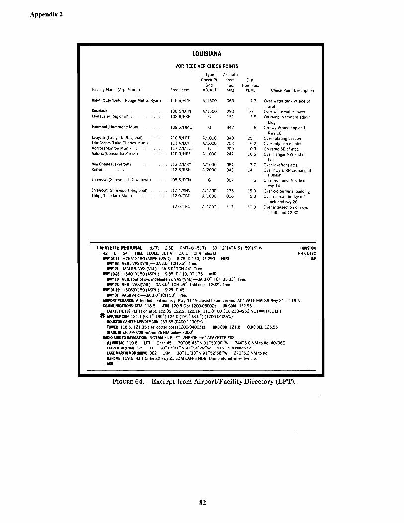
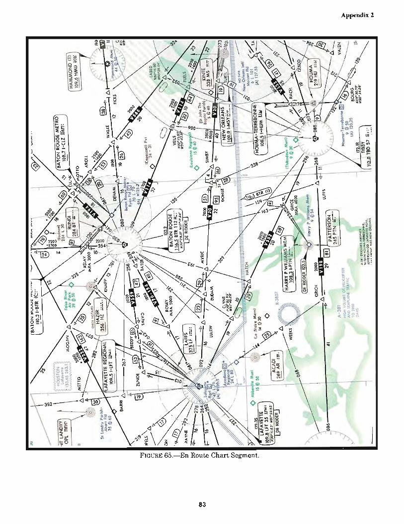
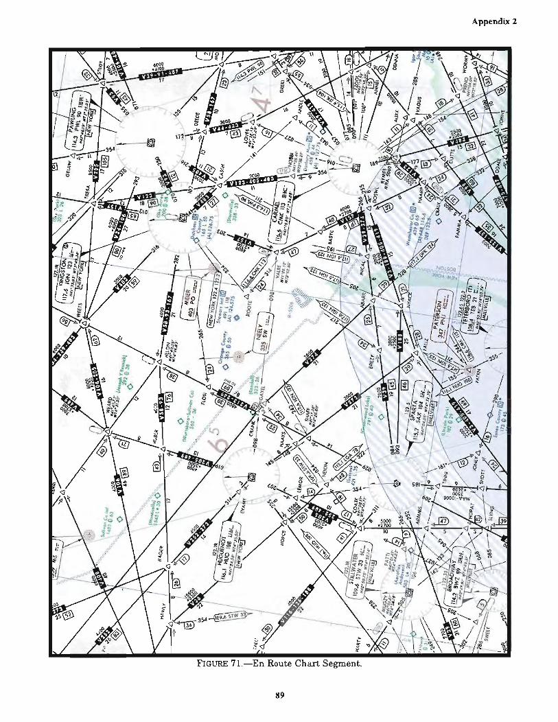
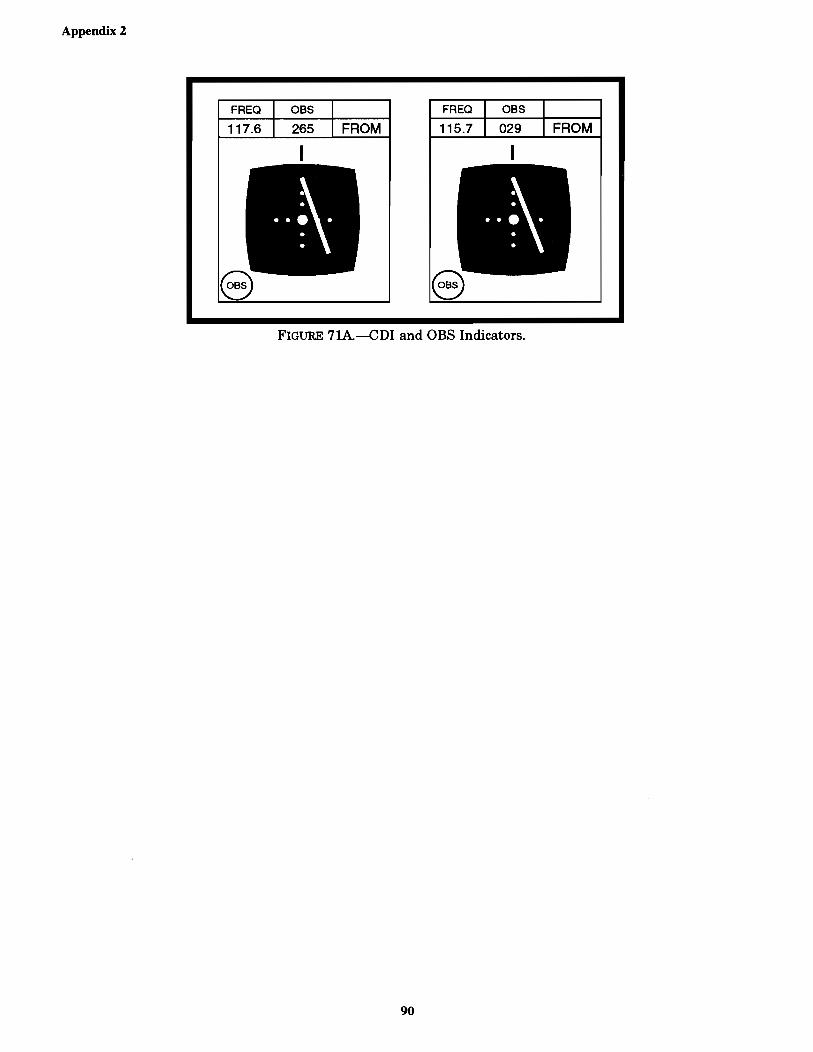
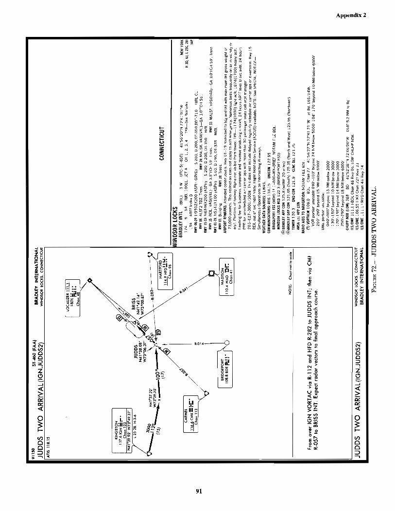
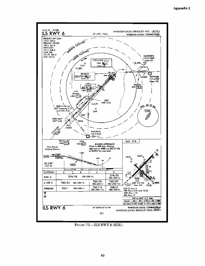
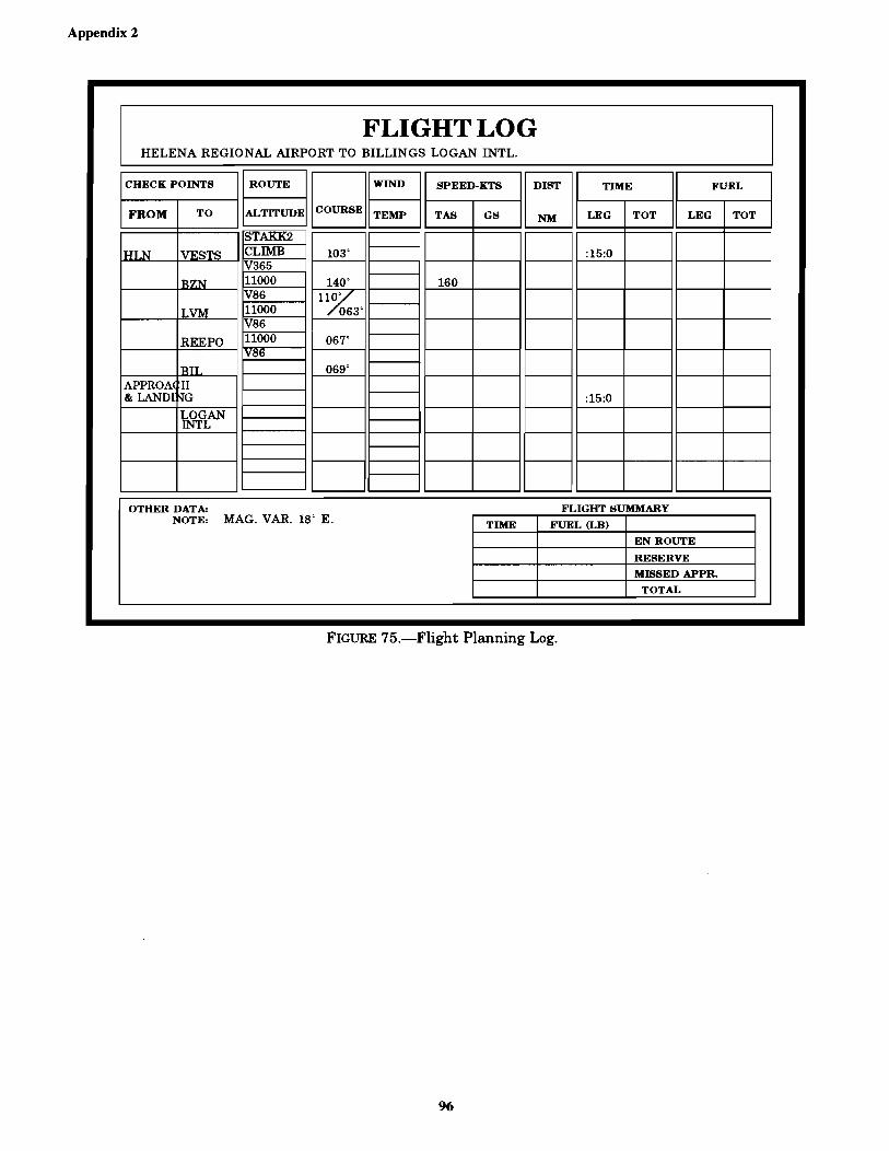
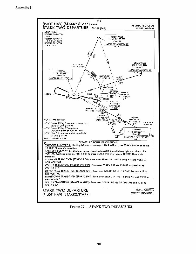
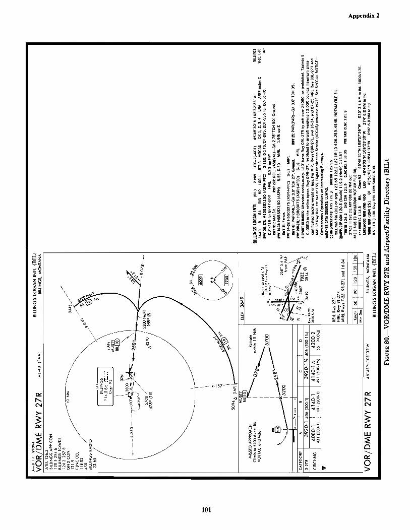
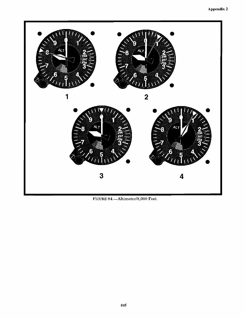
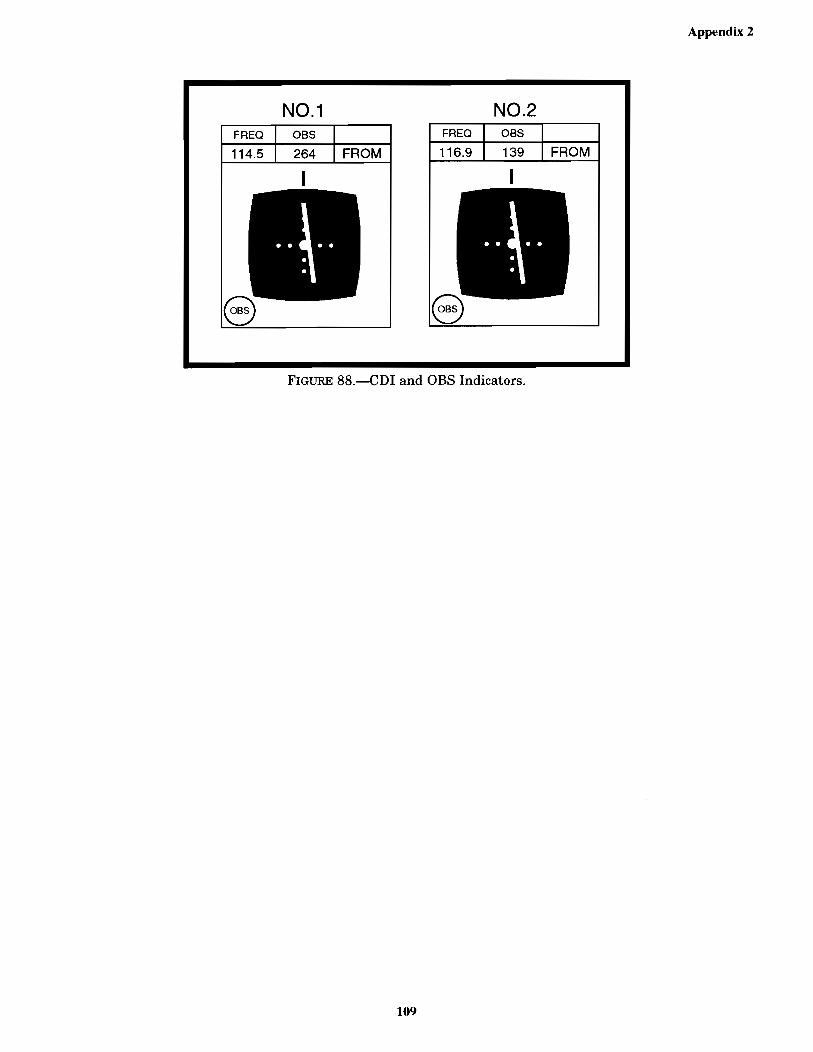
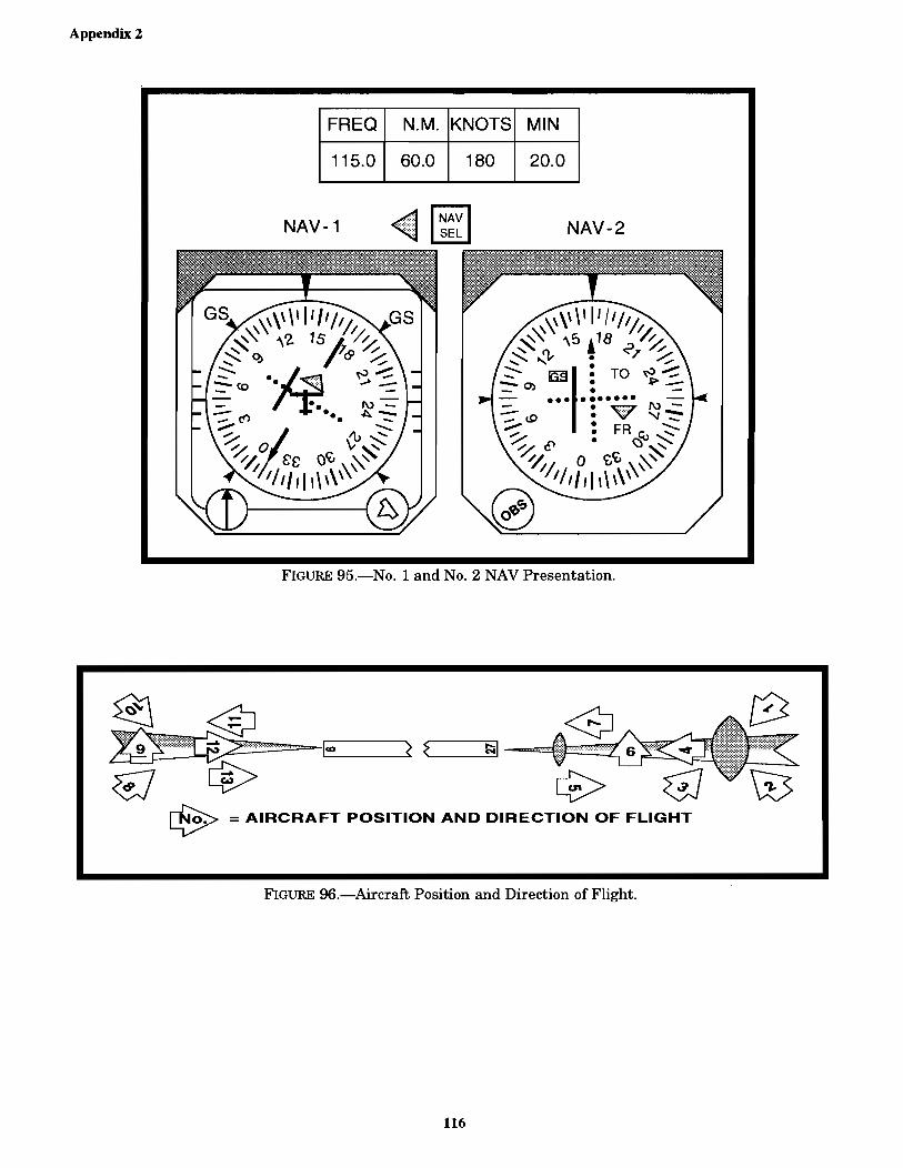
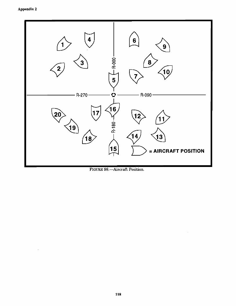
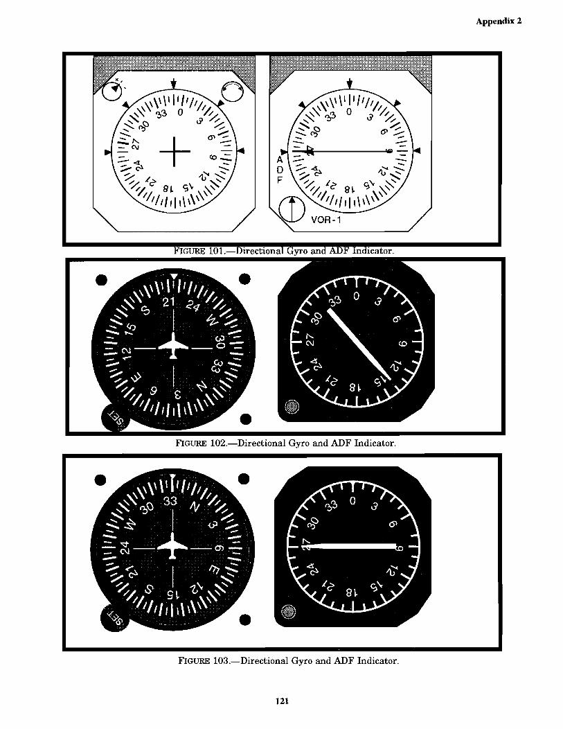
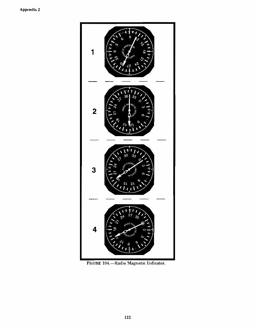
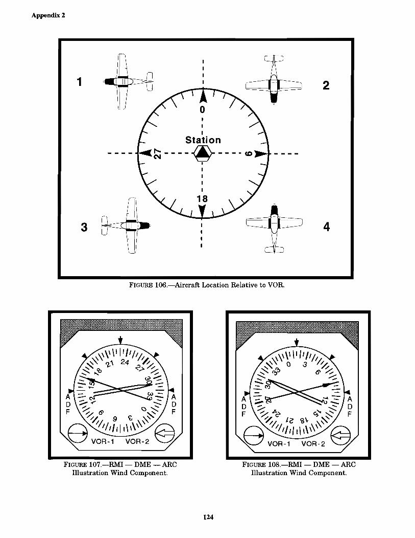
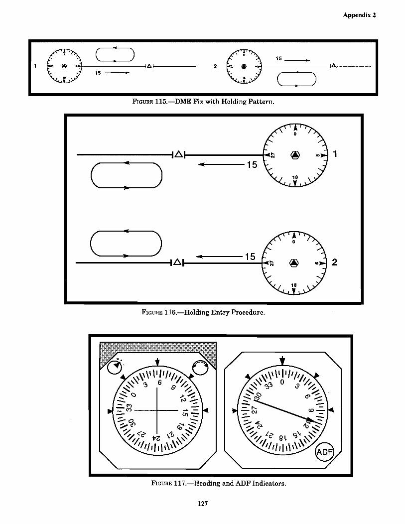
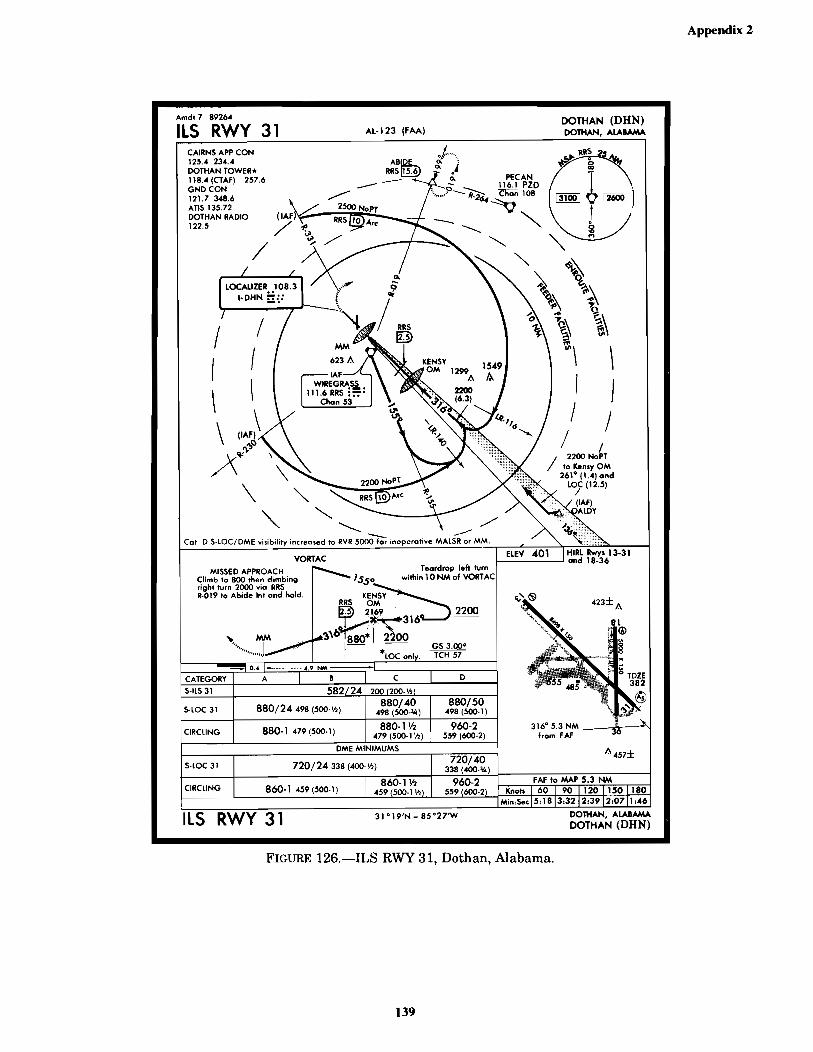
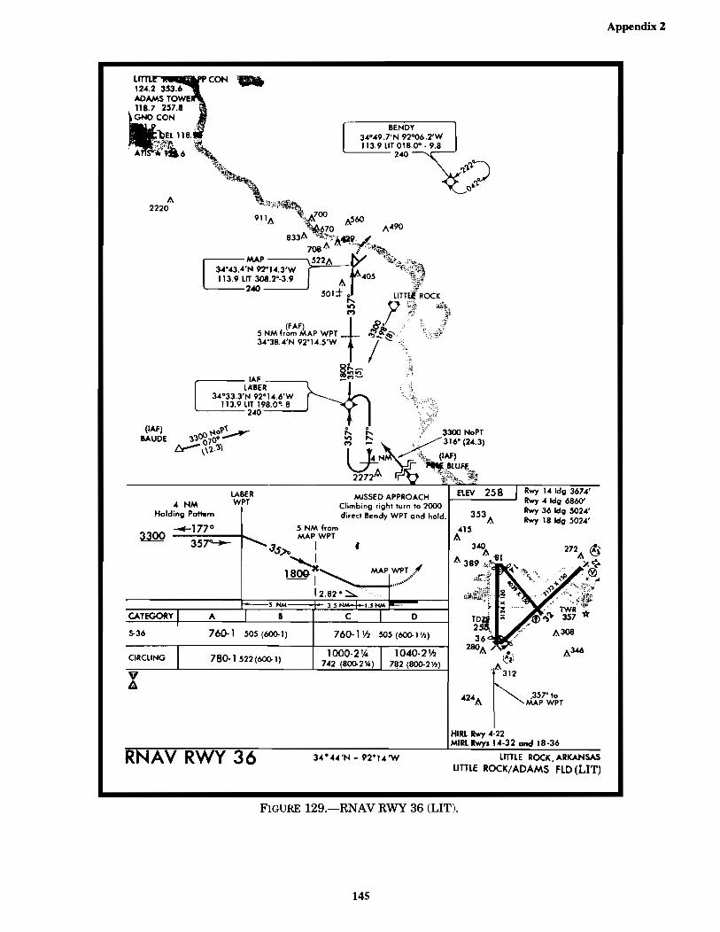
FIGURE 64.—Excerpt from Airport/Facility Directory (LFT) .............................................................................................82FIGURE 65.—En Route Chart Segment ...............................................................................................................................83FIGURE 66.—CDI and OBS Indicators ................................................................................................................................84FIGURE 67.—Localizer Symbol ...........................................................................................................................................84FIGURE 68.—COPTER VOR DME-117 Degrees (HUM) ..................................................................................................85FIGURE 69.—Flight Plan and Aircraft Information .............................................................................................................87FIGURE 70.—Flight Planning Log .......................................................................................................................................88FIGURE 71.—En Route Chart Segment ...............................................................................................................................89FIGURE 71A.—CDI and OBS Indicators .............................................................................................................................90FIGURE 72.—JUDDS TWO ARRIVAL ..............................................................................................................................91FIGURE 73.—ILS RWY 6 (BDL) ........................................................................................................................................93FIGURE 74.—Flight Plan and Aircraft Information .............................................................................................................95FIGURE 75.—Flight Planning Log .......................................................................................................................................96FIGURE 76.—VOR Indications and Excerpts from Airport/Facility Directory (HLN) .......................................................97FIGURE 77.—STAKK TWO DEPARTURE .......................................................................................................................98FIGURE 78.—En Route Chart Segment ...............................................................................................................................99FIGURE 79.—RMI Indicator ..............................................................................................................................................100FIGURE 80.—VOR/DME RWY 27R and Airport/Facility Directory (BIL) .....................................................................101FIGURE 81.—Dual VOR System, VOT Check ..................................................................................................................102FIGURE 82.—Dual VOR System, Accuracy Check...........................................................................................................103FIGURE 83.—Altimeter/12,000 Feet ..................................................................................................................................104FIGURE 84.—Altimeter/8,000 Feet ....................................................................................................................................105FIGURE 85.—WASHOE TWO DEPARTURE .................................................................................................................106FIGURE 86.—CDI and OBS Indicators ..............................................................................................................................107FIGURE 87.—En Route Chart Segment .............................................................................................................................108FIGURE 88.—CDI and OBS Indicators ..............................................................................................................................109FIGURE 89.—En Route Chart Segment .............................................................................................................................110FIGURE 90.—CDI/OBS Indicators ....................................................................................................................................111FIGURE 91.—En Route Chart Segment .............................................................................................................................112FIGURE 92.—Minimum In-Flight Visibility and Distance from Clouds. ..........................................................................113FIGURE 93.—New Airspace Classification .......................................................................................................................114FIGURE 94.—Application Examples for Holding Positions ..............................................................................................115FIGURE 95.—No. 1 and No. 2 NAV Presentation .............................................................................................................116FIGURE 96.—Aircraft Position and Direction of Flight .....................................................................................................116FIGURE 97.—HSI Presentation ..........................................................................................................................................117FIGURE 98.—Aircraft Position ..........................................................................................................................................118FIGURE 99.—HSI Presentation ..........................................................................................................................................119FIGURE 100.—RMI Illustrations .......................................................................................................................................120FIGURE 101.—Directional Gyro and ADF Indicator .........................................................................................................121FIGURE 102.—Directional Gyro and ADF Indicator .........................................................................................................121FIGURE 103.—Directional Gyro and ADF Indicator .........................................................................................................121FIGURE 104.—Radio Magnetic Indicator ..........................................................................................................................122FIGURE 105.—Aircraft Magnetic Heading and ADF Illustration .....................................................................................123FIGURE 106.—Aircraft Location Relative to VOR ...........................................................................................................124FIGURE 107.—RMI—DME—ARC Illustration Wind Component ..................................................................................124FIGURE 108.—RMI—DME—ARC Illustration Wind Component ..................................................................................124FIGURE 109.—CDI Direction from VORTAC ..................................................................................................................125FIGURE 110.—CDI Direction from VORTAC ..................................................................................................................125FIGURE 111.—CDI Direction from VORTAC ..................................................................................................................125FIGURE 112.—Holding Entry Procedure ...........................................................................................................................126FIGURE 113.—Aircraft Course and DME Indicator ..........................................................................................................126FIGURE 114.—Aircraft Course and DME Indicator ..........................................................................................................126FIGURE 115.—DME Fix with Holding Pattern .................................................................................................................127FIGURE 116.—Holding Entry Procedure ...........................................................................................................................127FIGURE 117.—Heading and ADF Indicators .....................................................................................................................127FIGURE 118.—ILS RWY 12L (DSM) ...............................................................................................................................128
CT-8080-3E FrontPages 04/18/2005, 4:52 PM7

viii
CONTENTS—Continued
Page
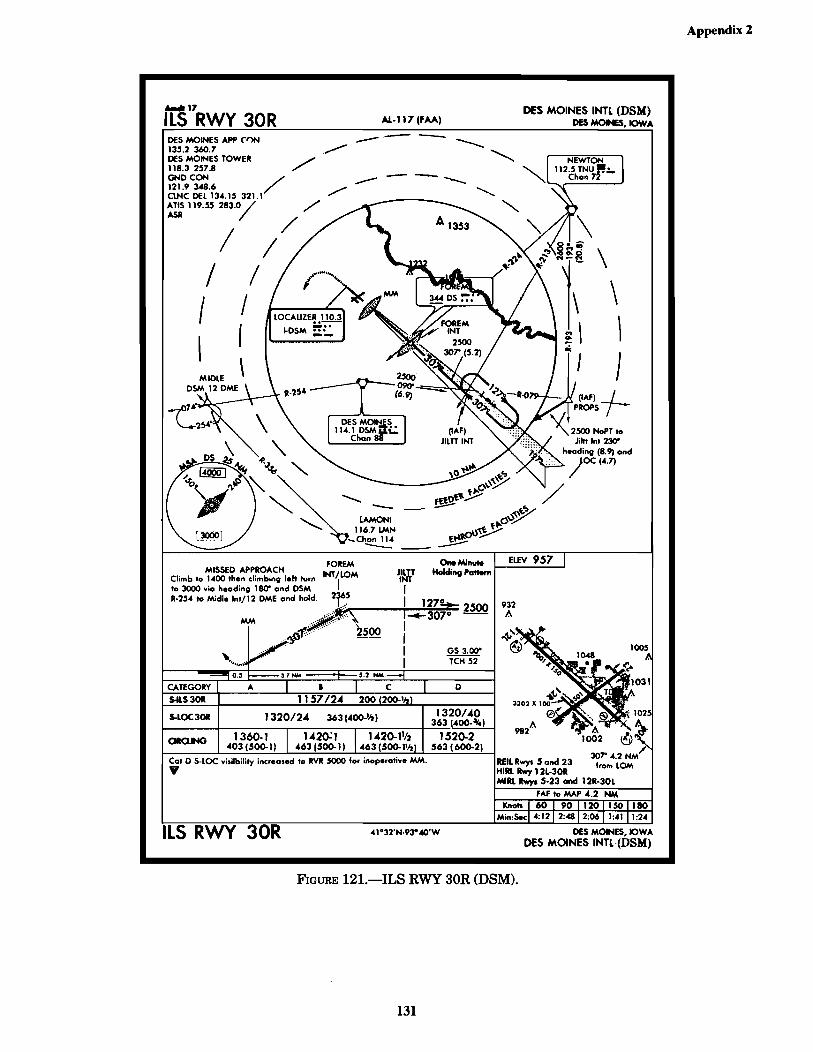
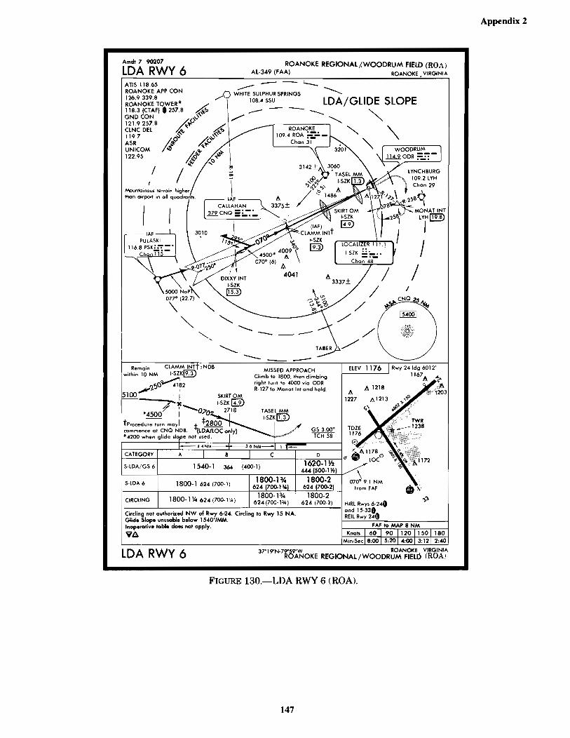
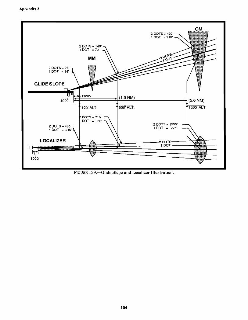
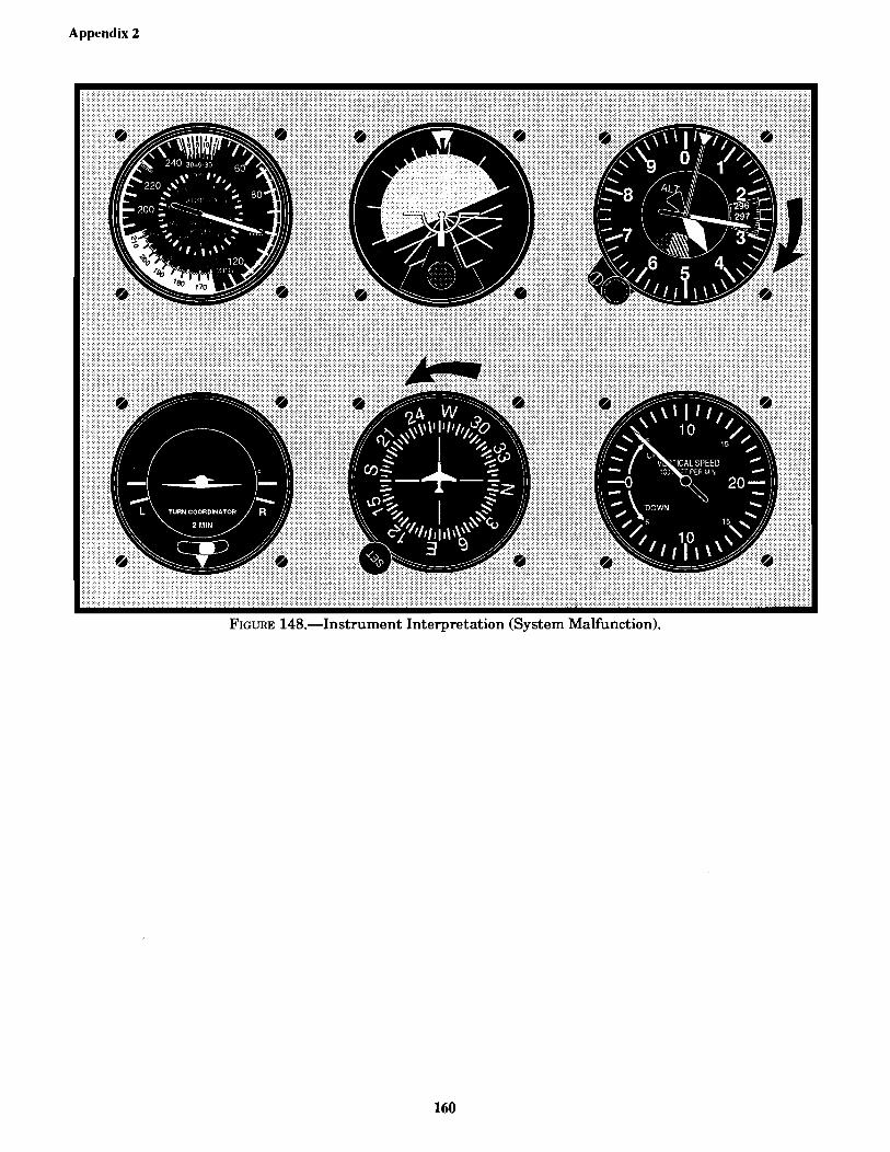
FIGURE 119.—ILS RWY 24R (LAX) ...............................................................................................................................129FIGURE 120.—ILS RWY 35R (DEN) ...............................................................................................................................130FIGURE 121.—ILS RWY 30R (DSM) ...............................................................................................................................131FIGURE 122.—ILS RWY 8L (ATL) ..................................................................................................................................132FIGURE 123.—VOR/DME-A (7D3) ..................................................................................................................................133FIGURE 124.—LOC RWY 35, Duncan, Oklahoma ...........................................................................................................135FIGURE 125.—ILS RWY 17R, Lincoln, Nebraska ............................................................................................................137FIGURE 126.—ILS RWY 31, Dothan, Alabama................................................................................................................139FIGURE 127.—NDB RWY 28, Lancaster/Fairfield County ..............................................................................................141FIGURE 128.—VOR RWY 36 (PUC) ................................................................................................................................143FIGURE 129.—RNAV RWY 36 (LIT) ...............................................................................................................................145FIGURE 130.—LDA RWY 6 (ROA) .................................................................................................................................147FIGURE 131.—VOR/DME RNAV RWY 4R ....................................................................................................................148FIGURE 132.—Deleted .......................................................................................................................................................149FIGURE 133.—ILS RWY 9 (RAL) ....................................................................................................................................151FIGURE 134.—2-BAR VASI .............................................................................................................................................152FIGURE 135.—3-BAR VASI .............................................................................................................................................152FIGURE 136.—Precision Approach Path Indicator (PAPI) ................................................................................................152FIGURE 137.—Precision Instrument Runway ....................................................................................................................153FIGURE 138.—Runway Legend .........................................................................................................................................153FIGURE 139.—Glide Slope and Localizer Illustration .......................................................................................................154FIGURE 140.—OBS, ILS, and GS Displacement ..............................................................................................................155FIGURE 141.—OBS, ILS, and GS Displacement ..............................................................................................................155FIGURE 142.—OBS, ILS, and GS Displacement ..............................................................................................................155FIGURE 143.—Slaved Gyro Illustration ............................................................................................................................156FIGURE 144.—Turn-and-Slip Indicator .............................................................................................................................156FIGURE 145.—Instrument Sequence (Unusual Attitude) ..................................................................................................157FIGURE 146.—Instrument Sequence (System Failed) .......................................................................................................158FIGURE 147.—Instrument Sequence (Unusual Attitude) ..................................................................................................159FIGURE 148.—Instrument Interpretation (System Malfunction) .......................................................................................160FIGURE 149.—Instrument Interpretation (System Malfunction) .......................................................................................161FIGURE 150.—Instrument Interpretation (Instrument Malfunction) .................................................................................162FIGURE 151.—Instrument Interpretation (Instrument Malfunction) .................................................................................163FIGURE 152.—RNAV (GPS) RWY 30, North Plate Regional Airport Lee Bird Field (LBF) ..........................................164FIGURE 153.—VOR/DME RWY 3, Norridgeworck/Central Main Airport of Norridgewock (OWK) ............................165FIGURE 154.—OshKosh/Wittman Regional (OSH) ..........................................................................................................166
CT-8080-3E FrontPages 04/18/2005, 4:52 PM8


164
Appendix 2
FIGURE 152.—RNAV (GPS) RWY 30, North Plate Regional Airport Lee Bird Field (LBF).
CT-8080-3E pages164-166 04/18/2005, 4:41 PM164
165
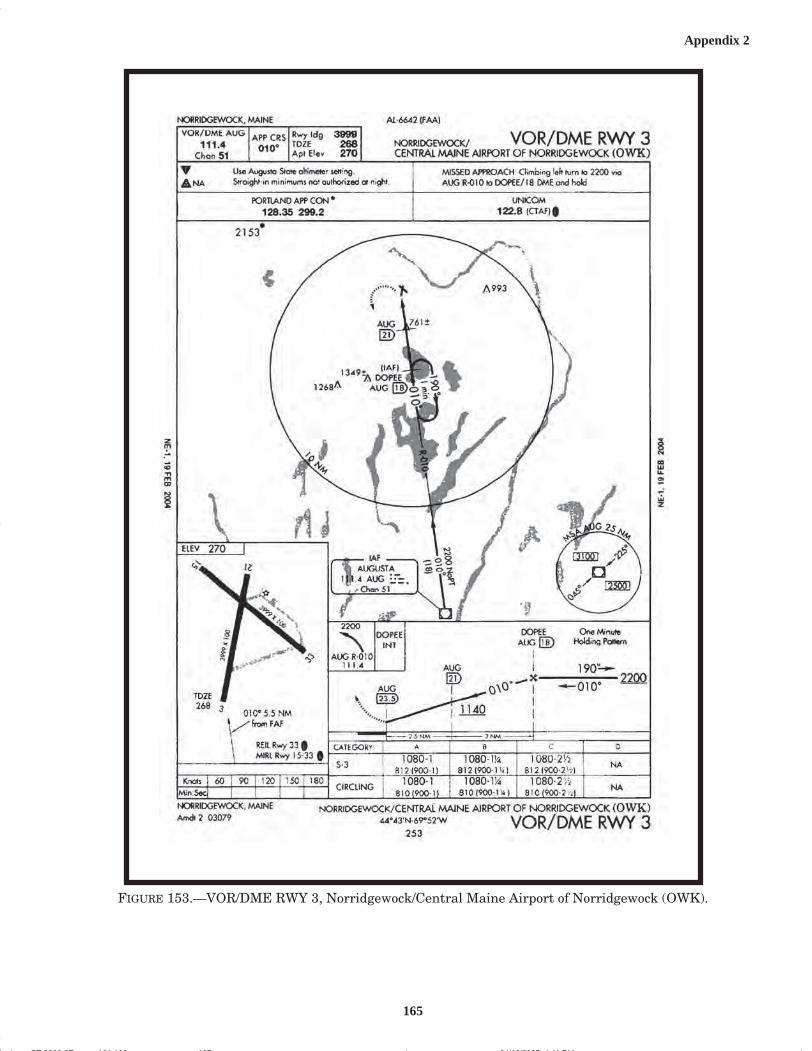
Appendix 2
FIGURE 153.—VOR/DME RWY 3, Norridgewock/Central Maine Airport of Norridgewock (OWK).
CT-8080-3E pages164-166 04/18/2005, 4:41 PM165

166
Appendix 2
FIGURE 154.—Osh Kosh/Wittman Regional (OSH).
CT-8080-3E pages164-166 04/18/2005, 4:41 PM166


