38
+ - G H Control Systems
| Date post: | 12-Dec-2015 |
| Category: |
Documents |
| Upload: | jayant-choudhary |
| View: | 212 times |
| Download: | 0 times |

+
-G
HContro
l Syste
ms

Books
• Modern Control Engineering By Katsuhiko Ogata
• Control Systems Engineering By I. J. Nagrath and M. Gopal

CONTROL PROBLEMCONTROL PROBLEM


Driving Control System

Input Output Configuration
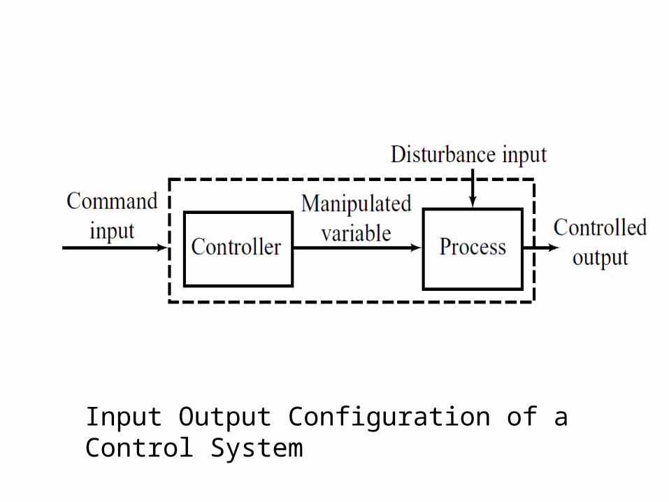
Input Output Configuration of a Control System

Some examples of control systems
• Liquid Level• Temperature• Position• Speed

Manual feedback control
of a thermal system

Steam
Drain
Thermometer
R
Hotwater
Cold water

Automatic feedback control
of a thermal system

RSteam
Controlvalve
Automaticcontroller
Temperaturemeasuring device
Hotwater
DrainColdwater

Components of a control system
PlantTransducerControllerAmplifierActuator

Liquid - level control system

---------------------------------------------------------------------------------------------------------
---
ControllerPneumatic
valve
Inflow
Outflow

Open Loop and Closed Loopcontrol system

Open Loop Thermal System

Open Loop Thermal System

Closed Loop Thermal System

Closed Loop Thermal System

Classification of control systems
• Open Loop / Closed Loop
• Linear/ Non Linear
• Time Invariant Parameter / Time Variant Parameter
• Lumped Parameter / Distributed Parameter
• Continuous time / Discrete time
• Analog / Digital

Systems involved
Electrical
Mechanical
Electromechanical
Hydraulic
Pneumatic
Thermal
Chemical
Non – Engineering

Mathematical Modeling
• Understand the concept
• Verbal description
• Physical diagram
• Block diagram or Signal flow graph
• Mathematical equations
• Transfer Function (Laplace Transforms)
• Measurement of parameters

SISO System in Transform Domain
A Transfer Function is the ratio of the output of a system to the input of a system, in the Laplace domain considering its initial conditions and equilibrium point to be zero.
)(
)()(
sR
sYsG

Electrical Systems
Elements
• R L C
Input
• Voltage (e) Current (i)
Output
• Voltage (e) Current (i)

Mechanical Systems
Elements
• M K B
Input
• force ( f )
Output
• Position (x) velocity ( v)

An Inertia Damper Model of Load

D C Motor

Armature Controlled D C Motor With Load

Block Diagram of Armature Controlled D C Motor

Single-Input Single-Output (SISO) System
Multi-Input Multi-Output (MIMO) System

Cascaded Non-loading Subsystems

Elements of a Block Diagram

General Linear Feedback System

Rules of Block Diagram Algebra

Rules of Block Diagram Algebra

An Example

Problem-1
Determine Y(s)/R(s)


