Page 1
PNNL-23045
Prepared for the U.S. Department of Energy under Contract DE-AC05-76RL01830
Concept Feasibility Report for Using Co-Extrusion to Bond Metals to Complex Shapes of U-10Mo CA Lavender A Soulami DM Paxton VV Joshi MT Smith DE Burkes December 2013
Page 3
PNNL-23045
Concept Feasibility Report for Using Co-Extrusion to Bond Metals to Complex Shapes of U-10Mo
CA Lavender A Soulami
DM Paxton VV Joshi
MT Smith DE Burkes
December 2013
Prepared for
the U.S. Department of Energy
under Contract DE-AC05-76RL01830
Pacific Northwest National Laboratory
Richland, Washington 99352
Page 5
iii
Abstract
In support of the Convert Program of the U.S. Department of Energy’s National Nuclear Security
Administration (DOE/NNSA) Global Threat Reduction Initiative (GTRI), Pacific Northwest National
Laboratory (PNNL) has been investigating manufacturing processes for the uranium-10% molybdenum
(U-10Mo) alloy plate fuel for the U.S. high-performance research reactors (USHPRR). This report
documents the results of PNNL’s efforts to develop the extrusion process for this concept. The approach
to the development of a co-extruded complex-shaped fuel has been described and an extrusion of DU-
10Mo was made. The initial findings suggest that given the extrusion forces required for processing U-
10Mo, the co-extrusion process can meet the production demands of the USHPRR fuel and may be a
viable production method. The development activity is in the early stages and has just begun to identify
technical challenges to address details such as dimensional tolerances and shape control. New extrusion
dies and roll groove profiles have been developed and will be assessed by extrusion and rolling of U-
10Mo during the next fiscal year. Progress on the development and demonstration of the co-extrusion
process for flat and shaped fuel is reported in this document.
Page 7
v
Acronyms and Abbreviations
304SS 304 stainless steel
AA6061 Aluminum Association Alloy 6061
BSE backscattered electron
DOE U.S. Department of Energy
DU depleted uranium
EDS energy dispersive x-ray spectroscopy
FY fiscal year
GTRI Global Threat Reduction Initiative
HFIR High Flux Isotope Reactor
SEM scanning electron microscopy
U-Mo uranium-molybdenum
U-10Mo uranium-10% molybdenum
USHPRR U.S. High-Performance Research Reactor
Page 9
vii
Contents
Abstract ............................................................................................................................................. iii
Acronyms and Abbreviations ............................................................................................................. v
1.0 Introduction ............................................................................................................................. 1.1
2.0 Conceptual Co-Extruded Complex Shaped U-10Mo GTRI Fuel Process ............................... 2.1
3.0 Results ..................................................................................................................................... 3.1
3.1 U-Mo Extrusion System Development Summary ........................................................... 3.1
3.2 Extrusion System Validation ........................................................................................... 3.3
3.3 Development of the Canned Extrusion Process .............................................................. 3.5
3.4 DU-10Mo Extrusion Demonstration ............................................................................... 3.6
3.5 Complex Shape Development ....................................................................................... 3.14
4.0 Discussion ................................................................................................................................ 4.1
5.0 Summary .................................................................................................................................. 5.1
6.0 References ............................................................................................................................... 6.1
Page 10
viii
Figures
1.1 Nominal As-Bonded Geometry of the USHPRR U-10Mo Fuel Prior to Final Shaping ......... 1.1
1.2 Schematic of the Co-extruded Alpha-Uranium Zirconium-Clad Fuel used in N-Reactor ....... 1.2
2.1 Optical Micrograph of the Cross-Section of a Co-Extruded U-Si Alloy with Zirconium
Cladding and a Fe-based Can .................................................................................................. 2.1
2.2 HFIR Fuel Element Contour Drawing ..................................................................................... 2.2
2.3 Co-Extruded Round and Elliptical Shapes to be Hot/Cold Rolled to the Final HFIR Shape .. 2.2
2.4 Schematic Representation of Rolling a Co-Extruded Shape to the Final HFIR Profile .......... 2.3
3.1 Major Components of the Extrusion Press Developed for U-Mo Co-Extrusion ..................... 3.2
3.2 PNNL Extrusion System Installed in a Radiologically Controlled Area.. ............................... 3.3
3.3 Extrusion Surface Finishes on AA6061 using Dag and Filled Grease Lubricants .................. 3.4
3.4 Load and Displacement Curves for AA6061 Extruded with Filled-Grease and Dag
Lubricants ................................................................................................................................ 3.4
3.5 Cross-Section of the Extruded 304SS and Cu-Based Alloy Can ............................................. 3.5
3.6 Force versus Displacement Curve for the Extrusion of 304 Stainless, Canned and Uncanned.3.6
3.7 DU-10Mo Casting from Which the Extrusion Billets were Machined. ................................... 3.7
3.8 Cu-based Alloy Can and U-10Mo Billet Prior to Assembly and Extrusion ............................ 3.8
3.9 DU-10Mo Extrusion Cooling in the Runout Tray after Extrusion .......................................... 3.8
3.10 Force–Displacement Diagram for the U-10Mo Extrusion and Stainless Steel Showing a
Relatively High Upset Force Followed by a Relatively Constant Running Force .................. 3.9
3.11 Backscattered SEM Image of the Transverse Section of the Middle Region of the As-Cast
Billets ..................................................................................................................................... 3.10
3.12 EDS Map of the As-Cast Sample Indicating the Presence of Silicon and Molybdenum in the
Script Regions and Uranium and Carbon in the Plate/Needle Regions ................................. 3.11
3.13 Macro-Images of the Extruded DU-10Mo Rod ..................................................................... 3.11
3.14 Low Magnification BSE-SEM Montage of the Tip of an Extrusion along the Longitudinal
Direction of the Extrusion ...................................................................................................... 3.12
3.15 High Magnification BSE-SEM Images of the Region of Microstructure Showing the Effect
of the Extrusion Strain on the Particle Fracture ..................................................................... 3.12
3.16 Elemental EDS Map of the As-Extruded Intermetallics and Carbides .................................. 3.13
3.17 Low Magnification BSE-SEM Images of the Extrusion at the Middle and Tail of the Sample
along the Extrusion Direction ................................................................................................ 3.13
3.18 The DU-10Mo Extrusion and the Peeled-Off Can Showing the Rough Surfaces ................. 3.14
3.19 Roll Groove Profiles for the Roll Pockets Needed to Roll a Complex Shaped Extrusion to
the HFIR Profile Using a Reduction Ratio of 3:1 .................................................................. 3.15
3.20 Streamlined Extrusion Die for the Shaped Co-Extrusion to be Rolled to the HFIR Profile .. 3.16
3.21 Engineered Drawings of the Roll Pockets for Rolling the Shaped Extrusion to the HFIR
Profile .................................................................................................................................... 3.17
Page 11
ix
Table
3.1 Nominal As-Cast Chemistry for the Casting from Which the Extrusion Billets
were Machined ......................................................................................................................... 3.7
Page 12
1.1
1.0 Introduction
In support of the Convert Program of the U.S. Department of Energy’s National Nuclear Security
Administration (DOE/NNSA) Global Threat Reduction Initiative (GTRI), Pacific Northwest National
Laboratory (PNNL) has been investigating manufacturing processes for the uranium-10% molybdenum
(U-10Mo) alloy plate fuel. The U-10Mo made with low-enriched uranium (LEU) has been identified as
the most promising alternative to the current highly enriched uranium used in the United States’ fleet of
high-performance research reactors (USHPRR) (1). The nominal configuration of the new LEU U-10Mo
plate fuel, shown in Figure 1.1, comprises a U-10Mo fuel foil enriched to slightly less than 20% U-235, a
thin Zr interlayer-diffusion barrier and a relatively thick cladding of 6061 aluminum (2). This new
configuration will require the use of processes and materials not currently in use, and as such, the Convert
Program is investigating several alternative approaches in order to rapidly determine the most cost-
effective and robust method for manufacturing the plate fuel. This report details the progress on the
alternative manufacturing process called co-extrusion.
Figure 1.1. Nominal As-Bonded Geometry of the USHPRR U-10Mo Fuel Prior to Final Shaping
Co-extrusion was used for many years in the DOE complex, particularly at the Hanford site, to
produce metallic uranium fuels (3). The fuels were typically alpha uranium metal clad by co-extrusion
with zirconium. The last reactor using metallic fuel at Hanford was the N-Reactor, which used an alpha
uranium annular fuel (a tube within a tube) as shown in Figure 1.2 (4).
Page 13
1.2
Figure 1.2. Schematic of the Co-extruded Alpha-Uranium Zirconium-Clad Fuel used in N-Reactor
Co-extrusion allows for a high-pressure and high-strain bonding process that results in a very high
quality metallurgical bond. There are many forms of co-extrusion; however, for reactive, high-strength
metals like zirconium and uranium in configurations that require tight dimensional control, the typical
process uses a machined uranium billet sleeved with zirconium and encapsulated with an outer can (5).
The outer can is normally evacuated and sealed to prevent ingress of air during preheat and extrusion. The
co-extrusion approach to be developed for the U-10Mo fuel will follow the zirconium-sleeve/outer-can
process used for N-Reactor fuels (6). This process will prevent air contamination of the interface between
Zr and U-10Mo and the machined U-10Mo billet will have the accurate dimensional control needed for
the USHPRR fuels. The approach to this process will be detailed in this report.
The performance of a USHPRR fuel is substantially different from that required for the weapons
reactors that used the alpha phase of uranium. For the USHPRR, the uranium gamma phase, stabilized by
10 weight percent molybdenum, will be required. This Mo addition extends the time for the equilibrium
for the deleterious transformation to alpha and gamma prime (U2Mo) to a long enough time to allow the
metallic fuel to be used in the USHPRRs (7). The addition of Mo to the uranium has been reported to
result in an order of magnitude increase in elevated temperature strength of the U-10Mo (8). The increase
in strength requires that the U-10Mo be extruded at higher temperatures under higher forces than are
required for alpha uranium.
Coincident with the GTRI co-extrusion development there has been activity at PNNL for the DOE
Office of Nuclear Energy Fuel Cycle Research and Development (FCRD) program to develop a
U-7Mo-X annular fuel (9). These coincident development activities have enabled leveraging of the
projects to reestablish the extrusion capability with the versatility to meet both project needs. The FCRD
project will extrude a tube using lower forces than are required for the complex shaped Zr-clad extrusion
needed for the GTRI fuel. An extrusion system and a billet canning line were built to accommodate both
projects. Progress in development, demonstration and validation of the extrusion system will be detailed
in this report.
Page 14
2.1
2.0 Conceptual Co-Extruded Complex Shaped U-10Mo GTRI Fuel Process
Past metallic uranium nuclear fuels were normally tubular like the example Zr-clad uranium-
(U-Si) fuel shown in
Figure 2.1 (prior to removal of the can). In this example, the uranium is the dark layer; it is clad on
the on the outside by a zirconium layer, which in turn is covered by a thin layer of the Fe-based can. For
the USHPRR, the extrusion would be solid.
Figure 2.1. Optical Micrograph of the Cross-Section of a Co-Extruded U-Si Alloy with Zirconium
Cladding and a Fe-based Can
The GTRI fuel is a substantially different configuration from that extruded previously for weapons
reactors. The GTRI fuel has the nominal configuration shown in Figure 1.2, where the uranium fuel is
clad with a thin interlayer of Zr called a diffusion barrier, which is clad with aluminum. The fuel
configurations for the USHPRR vary for each reactor and depending on location within the fuel bundle
normally require a final shaping by stamping. This configuration lends itself to a canned co-rolling
process, which is the current baseline process. However, the High Flux Isotope Reactor (HFIR), which
accounts for 40% of the annual fuel need, uses an “airfoil” shape shown in Figure 2.2 for the outer
element fuel plates (10).
U-Si alloy
Zr Clad
Fe-based alloy can
Page 15
2.2
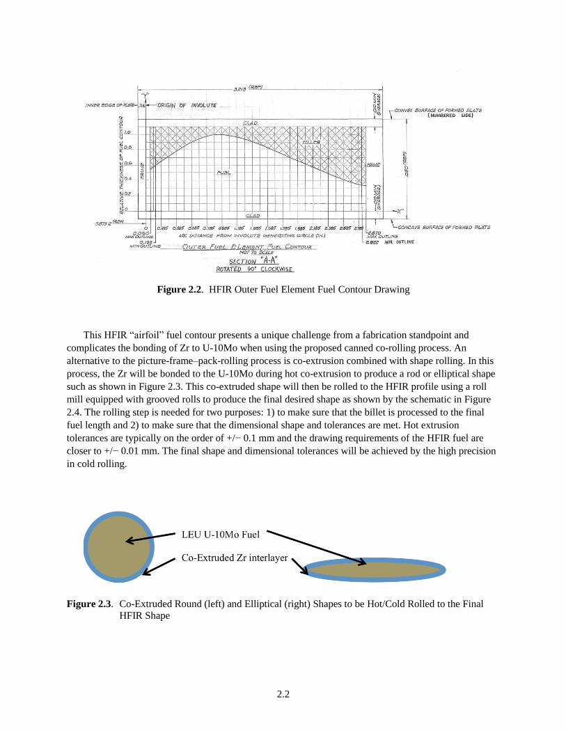
Figure 2.2. HFIR Outer Fuel Element Fuel Contour Drawing
This HFIR “airfoil” fuel contour presents a unique challenge from a fabrication standpoint and
complicates the bonding of Zr to U-10Mo when using the proposed canned co-rolling process. An
alternative to the picture-frame–pack-rolling process is co-extrusion combined with shape rolling. In this
process, the Zr will be bonded to the U-10Mo during hot co-extrusion to produce a rod or elliptical shape
such as shown in Figure 2.3. This co-extruded shape will then be rolled to the HFIR profile using a roll
mill equipped with grooved rolls to produce the final desired shape as shown by the schematic in Figure
2.4. The rolling step is needed for two purposes: 1) to make sure that the billet is processed to the final
fuel length and 2) to make sure that the dimensional shape and tolerances are met. Hot extrusion
tolerances are typically on the order of +/− 0.1 mm and the drawing requirements of the HFIR fuel are
closer to +/− 0.01 mm. The final shape and dimensional tolerances will be achieved by the high precision
in cold rolling.
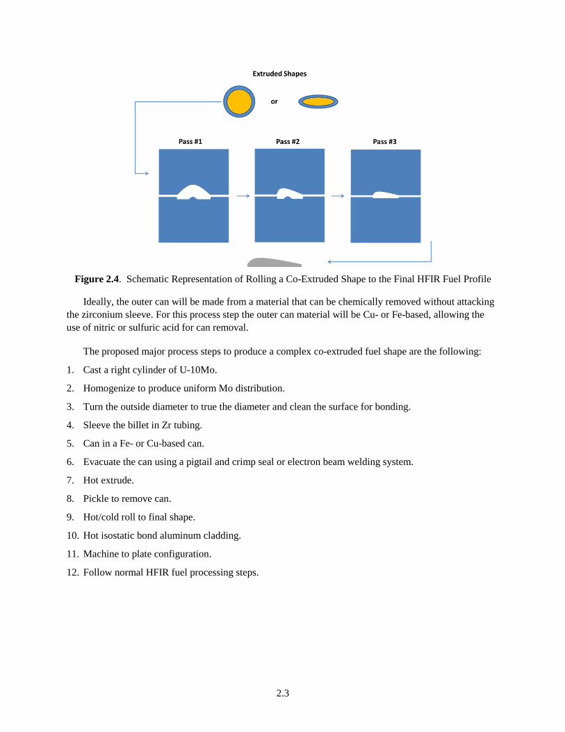
Figure 2.3. Co-Extruded Round (left) and Elliptical (right) Shapes to be Hot/Cold Rolled to the Final
HFIR Shape
Page 16
2.3
Figure 2.4. Schematic Representation of Rolling a Co-Extruded Shape to the Final HFIR Fuel Profile
Ideally, the outer can will be made from a material that can be chemically removed without attacking
the zirconium sleeve. For this process step the outer can material will be Cu- or Fe-based, allowing the
use of nitric or sulfuric acid for can removal.
The proposed major process steps to produce a complex co-extruded fuel shape are the following:
1. Cast a right cylinder of U-10Mo.
2. Homogenize to produce uniform Mo distribution.
3. Turn the outside diameter to true the diameter and clean the surface for bonding.
4. Sleeve the billet in Zr tubing.
5. Can in a Fe- or Cu-based can.
6. Evacuate the can using a pigtail and crimp seal or electron beam welding system.
7. Hot extrude.
8. Pickle to remove can.
9. Hot/cold roll to final shape.
10. Hot isostatic bond aluminum cladding.
11. Machine to plate configuration.
12. Follow normal HFIR fuel processing steps.
Page 17
3.1
3.0 Results
3.1 U-Mo Extrusion System Development Summary
The design objectives of the extrusion development task were to develop an extrusion press system
capable of direct extrusion of billets having elevated high-temperature flow stress. Included in this
category are the family of materials that are considered “difficult to extrude” such as stainless steels,
titanium, steels, and uranium (5). In order to develop a commercially feasible USHPRR fuel design and
production process it is necessary to demonstrate the ability to extrude a cast uranium-molybdenum
(U-Mo) ingot into a smaller rod or shape for cold rolling into a shaped product form. Although some
extrusion of alpha phase uranium fuels has been done on a large scale in the past (3), very limited
capability currently exists within industry or the DOE laboratory complex for the extrusion of uranium.
The design of the PNNL extrusion press system focused on being able to extrude U-Mo billets of less
than 1.0 inch in diameter using extrusion reduction ratios of between 3 and 16. This would enable PNNL
to produce a rod or elliptical product of suitable size for testing in the Advanced Test Reactor (ATR) at
Idaho National Laboratory. Extrusion temperatures of up to 900°C were used as the basis for tooling
material selection and operational requirements. Development of a bench-top extrusion system that is
designed around small diameter billets presents a number of technical challenges. Large commercial
extrusion presses process large-diameter metal billets having large thermal mass. In contrast, the PNNL
bench-top extrusion press system must be able to extrude at high temperatures small billets that have low
thermal mass and high surface area, both of which can lead to excessive temperature drop and contribute
to high friction. Key requirements of the process to overcome these challenges are the use of heated
tooling, a rapid billet loading process, and the selection of suitable high temperature lubricants.
During the course of FY12 and into FY13 the extrusion development task focused on a series of six
subtasks listed below. For brevity, more-detailed information on Subtasks 1 through 4 can be found in
PNNL-22730.1
1. Extrusion Equipment Design and Stress Analysis
2. Detailed Mechanical Design and Tooling Fabrication
3. Control System Development
4. Assembly and Functional Testing
5. Operational Development and Validation
6. Development of the Canned Extrusion Process
Forces required to extrude the “difficult to extrude” materials such as stainless steel and uranium
alloys are typically quite high. The project generated a finite element model for the main components of
the system and the resulting stress analysis was used to size and design the major extrusion system
components. For direct extrusion, the limiting stresses occur in the stem (which is the approximate
diameter of the inside of the container liner). The use of high quality hot working steels (such as H-13 and
H-21) provides a safe working stress of approximately 190,000 psi. This stress limit then determines the
1Bennett WD et al. 2013. FY-13 Status Report for the U-Mo Concept. PNNL-22730, Pacific Northwest National
Laboratory, Richland, Washington.
Page 18
3.2
size of the hydraulic ram and the design of the container. For the container, a three-part shrink fit design
provides for higher safe working pressures by introducing compressive stresses between each of the
cylinders, which acts to keep stress levels for the heated container temperature (450°C) at safe working
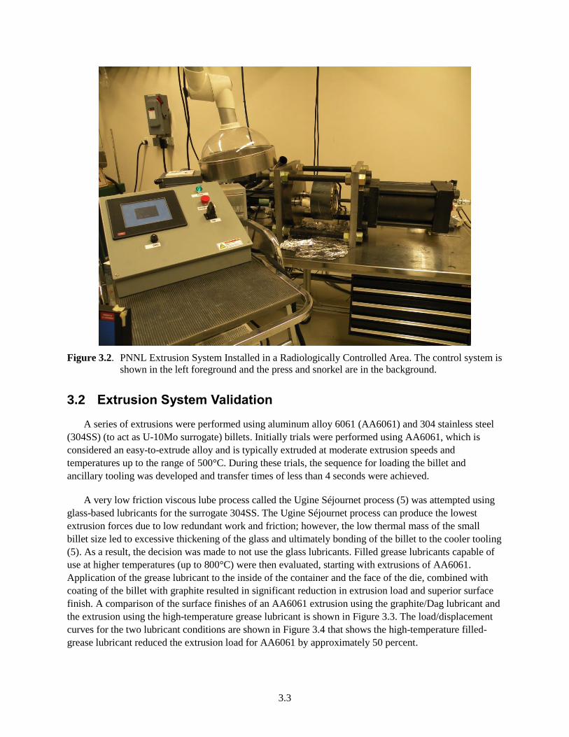
levels. A schematic of the key features is given in Figure 3.1.
Figure 3.1. Major Components of the Extrusion Press Developed for U-Mo Co-Extrusion
During FY13 a small-scale extrusion facility was designed and constructed and the extrusion press
was set up in a radiologically controlled area to begin extrusion of depleted uranium (DU)-10Mo billets.
The configuration of the complete bench-top extrusion press with supporting furnace and billet loading
system is shown in Figure 3.2 as installed in the radiologically controlled area. The PNNL system can be
summarized as follows: it has a variable and programmable ram speed, controllable tooling temperatures
up to 450°C, and a versatile die stack that allows conical, streamline, bridge, and shear die extrusion. The
extrusions can be tubular, shaped or rods and are not limited in length. Length is limited by the billet flow
stress that limits extrusion ratio and maximum ram stroke of approximately 12" with 6" of daylight. Billet
preheat is carried out in resistance furnaces and is limited to a maximum of 1100°C. Higher temperatures
would require different heating systems. Maximum extrusion force is 75 tons and maximum ram speed is
45 inches per minute.
Main hydraulic
cylinder and ram
Rear plate and tie rods
Extrusion container
with integral heaters Front plate with
die ring attached
Auxiliary hydraulic cylinders
Runout tray
Billet loading systems
Page 19
3.3
Figure 3.2. PNNL Extrusion System Installed in a Radiologically Controlled Area. The control system is
shown in the left foreground and the press and snorkel are in the background.
3.2 Extrusion System Validation
A series of extrusions were performed using aluminum alloy 6061 (AA6061) and 304 stainless steel
(304SS) (to act as U-10Mo surrogate) billets. Initially trials were performed using AA6061, which is
considered an easy-to-extrude alloy and is typically extruded at moderate extrusion speeds and
temperatures up to the range of 500°C. During these trials, the sequence for loading the billet and
ancillary tooling was developed and transfer times of less than 4 seconds were achieved.
A very low friction viscous lube process called the Ugine Séjournet process (5) was attempted using
glass-based lubricants for the surrogate 304SS. The Ugine Séjournet process can produce the lowest
extrusion forces due to low redundant work and friction; however, the low thermal mass of the small
billet size led to excessive thickening of the glass and ultimately bonding of the billet to the cooler tooling
(5). As a result, the decision was made to not use the glass lubricants. Filled grease lubricants capable of
use at higher temperatures (up to 800°C) were then evaluated, starting with extrusions of AA6061.
Application of the grease lubricant to the inside of the container and the face of the die, combined with
coating of the billet with graphite resulted in significant reduction in extrusion load and superior surface
finish. A comparison of the surface finishes of an AA6061 extrusion using the graphite/Dag lubricant and
the extrusion using the high-temperature grease lubricant is shown in Figure 3.3. The load/displacement
curves for the two lubricant conditions are shown in Figure 3.4 that shows the high-temperature filled-
grease lubricant reduced the extrusion load for AA6061 by approximately 50 percent.
Page 20
3.4
Figure 3.3. Extrusion Surface Finishes on AA6061 using Dag (top) and Filled Grease (bottom)
Lubricants
Figure 3.4. Load and Displacement Curves for AA6061 Extruded with Filled-Grease and Dag Lubricants
0
Forc
e
Displacement
AL6061 BullNose GreaseLubeAL6061 BullNose Oil BasedDag Lube
Page 21
3.5
3.3 Development of the Canned Extrusion Process
In order to make sure the interface between the Zr and the U-10Mo is clean, an outer can that acts as a
hermetic barrier is required to prevent oxidation of the U-10Mo and Zr during billet preheat and
extrusion. The challenge for canned extrusion is the selection of the can materials. The can must be
weldable for sealing, oxidation resistant and ideally has a flow stress that matches the material to be
extruded. Alternatively, the outer can may be used to provide a softer outer layer having lower flow stress
and low reactivity with the steel extrusion tooling. Copper canning of uranium extrusions was a standard
practice for extruding N-Reactor fuels (11). This canning process resulted in lower extrusion forces and
less oxidation of the DU billet. For simplicity in the initial trials, it was decided that canning of the billet
with copper-based alloys using the high-temperature grease lubricant should be the focus of further
extrusion process development.
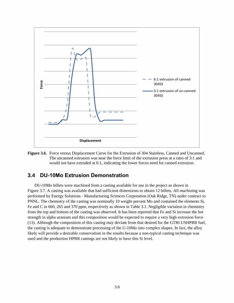
To validate the performance of the extrusion press at near-maximum stress levels, billets of 304SS
were machined and fitted to the copper-based alloys and extruded at temperatures up to 850°C using a
high-temperature filled-grease lubricant. Although generating significantly higher extrusion forces than
AA6061, the canned 304SS was extruded successfully at loads sufficiently below the extrusion press
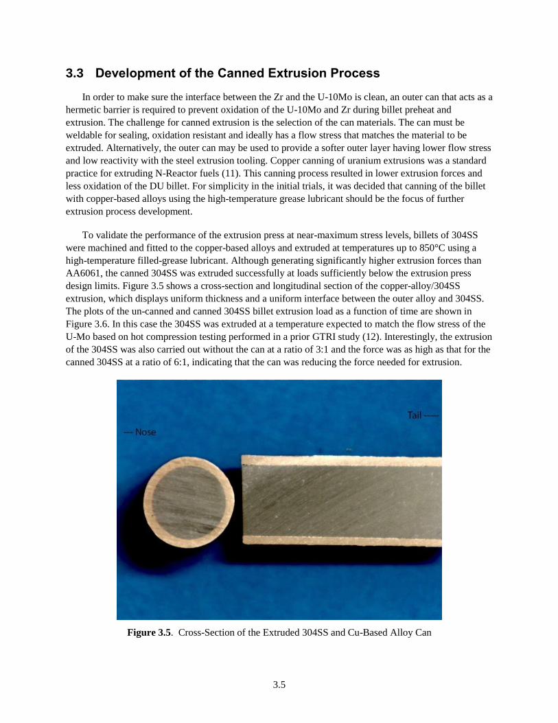
design limits. Figure 3.5 shows a cross-section and longitudinal section of the copper-alloy/304SS
extrusion, which displays uniform thickness and a uniform interface between the outer alloy and 304SS.
The plots of the un-canned and canned 304SS billet extrusion load as a function of time are shown in
Figure 3.6. In this case the 304SS was extruded at a temperature expected to match the flow stress of the
U-Mo based on hot compression testing performed in a prior GTRI study (12). Interestingly, the extrusion
of the 304SS was also carried out without the can at a ratio of 3:1 and the force was as high as that for the
canned 304SS at a ratio of 6:1, indicating that the can was reducing the force needed for extrusion.
Figure 3.5. Cross-Section of the Extruded 304SS and Cu-Based Alloy Can
Page 22
3.6
Figure 3.6. Force versus Displacement Curve for the Extrusion of 304 Stainless, Canned and Uncanned.
The uncanned extrusion was near the force limit of the extrusion press at a ratio of 3:1 and
would not have extruded at 6:1, indicating the lower forces need for canned extrusion.
3.4 DU-10Mo Extrusion Demonstration
DU-10Mo billets were machined from a casting available for use in the project as shown in
Figure 3.7. A casting was available that had sufficient dimensions to obtain 12 billets. All machining was
performed by Energy Solutions - Manufacturing Sciences Corporation (Oak Ridge, TN) under contract to
PNNL. The chemistry of the casting was nominally 10 weight percent Mo and contained the elements Si,
Fe and C in 660, 265 and 370 ppm, respectively as shown in Table 3.1. Negligible variation in chemistry
from the top and bottom of the casting was observed. It has been reported that Fe and Si increase the hot
strength in alpha uranium and this composition would be expected to require a very high extrusion force
(13). Although the composition of this casting may deviate from that desired for the GTRI USHPRR fuel,
the casting is adequate to demonstrate processing of the U-10Mo into complex shapes. In fact, the alloy
likely will provide a desirable conservatism in the results because a non-typical casting technique was
used and the production HPRR castings are not likely to have this Si level.
Forc
e
Displacement
6:1 extrusion of canned304SS
3:1 extrusion of un-canned304SS
Page 23
3.7
Figure 3.7. DU-10Mo Casting from Which the Extrusion Billets were Machined. The images of the
billets show their relative positions in the casting.
Table 3.1. As-Cast Chemistry for the Log Casting from Which the Extrusion Billets were Machined
Molybdenum Carbon Silicon Iron Total Others Uranium
Weight Percent ppm ppm ppm ppm
Top 10.4 370 650 250 <100 Balance
Bottom 10.3 370 670 280 <100 Balance
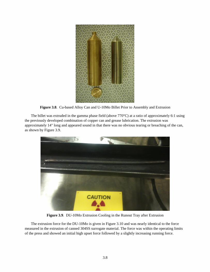
After machining, the DU-10Mo billets looked like the billet shown on the right side of Figure 3.8. No
gross flaws were found in any of the billets and the surfaces after machining were smooth and on the
order of 16 microinches of roughness. Initially, one DU-10Mo extrusion billet was canned using the can
shown on the left side of Figure 3.8. Because there was no attempt to bond in the initial extrusion, the can
lid was peened to hold the lid in place rather than welded.
Page 24
3.8
Figure 3.8. Cu-based Alloy Can and U-10Mo Billet Prior to Assembly and Extrusion
The billet was extruded in the gamma phase field (above 770°C) at a ratio of approximately 6:1 using
the previously developed combination of copper can and grease lubrication. The extrusion was
approximately 14" long and appeared sound in that there was no obvious tearing or breaching of the can,
as shown by Figure 3.9.
Figure 3.9. DU-10Mo Extrusion Cooling in the Runout Tray after Extrusion
The extrusion force for the DU-10Mo is given in Figure 3.10 and was nearly identical to the force
measured in the extrusion of canned 304SS surrogate material. The force was within the operating limits
of the press and showed an initial high upset force followed by a slightly increasing running force.
Page 25
3.9
Figure 3.10. Force–Displacement Diagram for the U-10Mo and canned 6:1 Stainless Steel Extrusion
Showing a Relatively High Upset Force Followed by a Relatively Constant Running Force
Microstructural characterization was performed on the casting from which the billets were machined
and on the extruded rods. The as-cast samples were cut along the transverse direction for microstructural
characterization and samples were obtained from the top, middle and bottom sections of the casting. The
as-extruded rods were cut along the extrusion axis (longitudinal section) for microstructural
characterization. Samples from the front, middle and tail of the extruded rods were used for the
microstructural characterization.
For the microstructural analysis, samples were cold mounted in an epoxy resin. The mounted samples
were successively polished to 600 grit with SiC polishing papers and were further polished using 6m
and 1m diamond slurries, followed by a final colloidal silica polish. Upon polishing, the samples were
gold coated for scanning electron microscopy (SEM) analysis. The detailed technique used to prepare the
samples for characterization can be found in Reference (12). Microstructural characterization was
performed using an optical microscope as well as using a JEOL JSM-7600F SEM equipped with an
Oxford Instruments X-Max 80 energy dispersive x-ray spectroscopy (EDS) detector. The EDS analysis
was performed using the INCA Microanalysis Suite software, version 4.15.
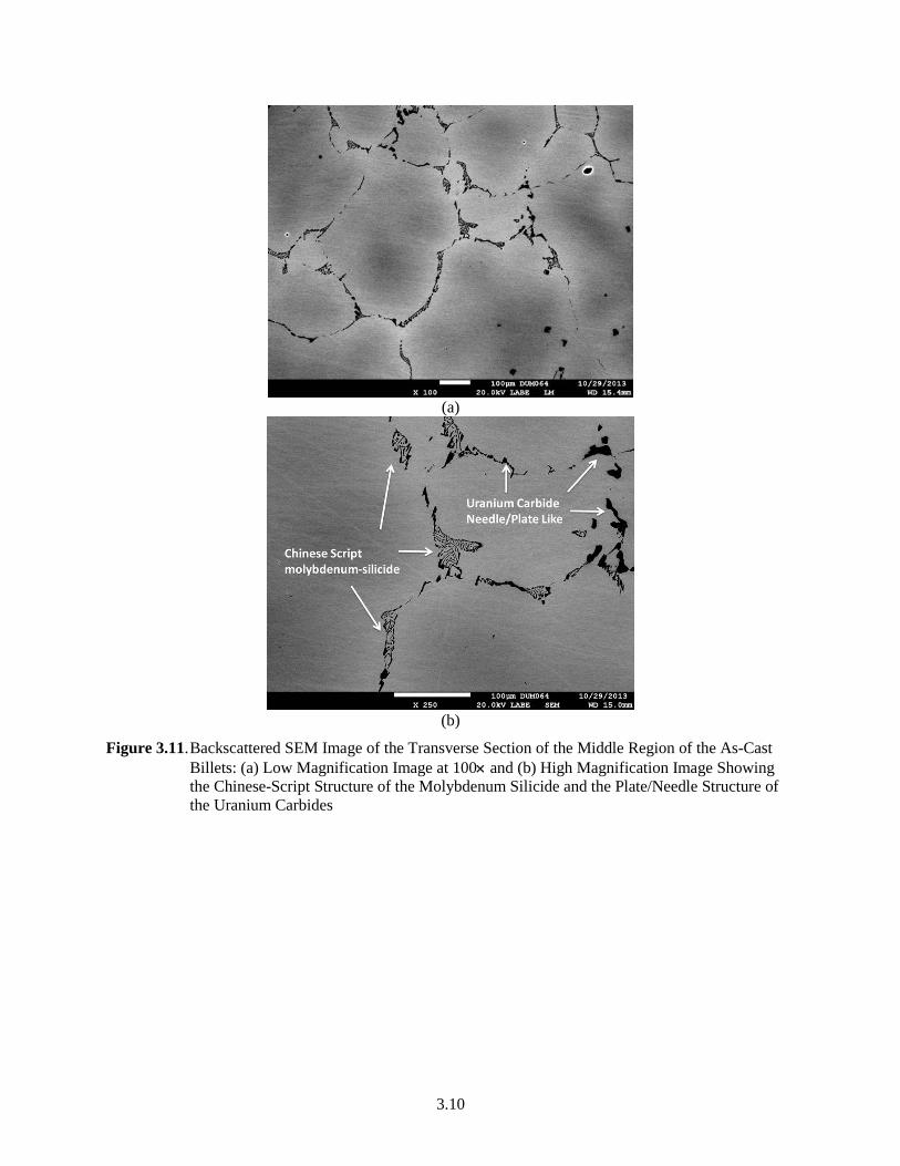
Figure 3.11a is the backscattered SEM image of the as-cast/as-received sample taken from the middle
section of the billet. The microstructure of the bottom and top regions (not shown) closely resembled that
of the middle section. It was observed that the grain size of the as-cast sample ranged between 300 and
500 m and was bimodal in distribution. The grain boundaries were decorated by Chinese-script
molybdenum silicide and plate/needle shaped uranium carbide as shown in Figure 3.11b. Based on the
backscattered electron (BSE) image (Z-contrast) and subsequent EDS analysis, given in Figure 3.12,
microsegregation of molybdenum was observed within the grains. Based on the EDS analysis, it was
determined that the difference in the molybdenum concentration within the grains and along the grain
boundaries was approximately 2–3 weight percent, i.e., the centers of the grains were rich in
molybdenum.
Forc
e
Displacement
DU-10Mo
Stainless Steel
Page 26
3.10
(a)
(b)
Figure 3.11. Backscattered SEM Image of the Transverse Section of the Middle Region of the As-Cast
Billets: (a) Low Magnification Image at 100 and (b) High Magnification Image Showing
the Chinese-Script Structure of the Molybdenum Silicide and the Plate/Needle Structure of
the Uranium Carbides
Page 27
3.11
Figure 3.12. EDS Map of the As-Cast Sample Indicating the Presence of Silicon and Molybdenum in the
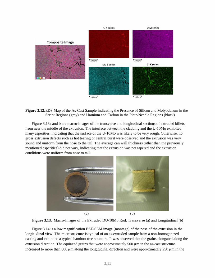
Script Regions (gray) and Uranium and Carbon in the Plate/Needle Regions (black)
Figure 3.13a and b are macro-images of the transverse and longitudinal sections of extruded billets
from near the middle of the extrusion. The interface between the cladding and the U-10Mo exhibited
many asperities, indicating that the surface of the U-10Mo was likely to be very rough. Otherwise, no
gross extrusion defects such as hot tearing or central burst were observed and the extrusion was very
sound and uniform from the nose to the tail. The average can wall thickness (other than the previously
mentioned asperities) did not vary, indicating that the extrusion was not tapered and the extrusion
conditions were uniform from nose to tail.
(a) (b)
Figure 3.13. Macro-Images of the Extruded DU-10Mo Rod: Transverse (a) and Longitudinal (b)
Figure 3.14 is a low magnification BSE-SEM image (montage) of the nose of the extrusion in the
longitudinal view. The microstructure is typical of an as-extruded sample from a non-homogenized
casting and exhibited a typical bamboo-tree structure. It was observed that the grains elongated along the
extrusion direction. The equiaxed grains that were approximately 500 m in the as-cast structure
increased to more than 800 m along the longitudinal direction and were approximately 250 m in the
Page 28
3.12
transverse direction. The smaller grains elongated to approximately 500 m along the extrusion axis
whereas the grain size was less than 50 m perpendicular to it. The segregation of the molybdenum
within the grains was retained and appeared to have formed bands. The silicides and carbides were
present at the grain boundaries. It was observed that the density of the intermetallics and carbides was
higher at the narrow ends of the coarse grains and fairly uniform around the finer grains, as shown in
Figure 3.14. There was no evidence of (macro) porosity across the entire cross-section.
Figure 3.14. Low Magnification BSE-SEM Montage of the Tip of an Extrusion along the Longitudinal
Direction of the Extrusion
(a) (b)
Figure 3.15. High Magnification BSE-SEM Images of the Region of Microstructure Showing the Effect
of the Extrusion Strain on the Particle Fracture
Figure 3.15a and b are high resolution BSE-SEM images that show the effect of extrusion on the
intermetallics and carbides, which were located at the grain boundaries in the as-cast structure. Figure
3.16 is the elemental EDS map of Figure 3.15 Based on the distribution of the silicides and carbides, as
shown in Figure 3.15, it was concluded that the extrusion process caused the Chinese-script molybdenum
silicides (black) and plate/needle-like carbides (gray) to be completely broken down and form isolated
clusters along the grain boundaries. These particles appeared to have fractured into two or more parts and
in certain cases voids were visible within the interparticle regions. The carbides in Figure 3.15a that had a
lower aspect ratio seemed to have remained intact during extrusion and were not fractured, as indicated
by the lack of porosity around the particles. Particle sizes of the intermetallics varied from 1–6 m in
length and 0.5–2 m in width.
Page 29
3.13
Figure 3.16. Elemental EDS Map of the As-Extruded Intermetallics and Carbides
The extrusion appeared to reduce the cast structure uniformly form nose to tail, indicating little
change in the condition of the extrusion from start to finish. Figure 3.17 shows an example of the
uniformity of the structure from start to finish, indicating a relatively homogeneous reduction occured
during extrusion.
(a) (b)
Figure 3.17. Low Magnification BSE-SEM Images of the Extrusion at the Middle (a) and Tail (b) of the
Sample along the Extrusion Direction
As expected from the asperities shown in the transverse cross-section of the extrusion in Figure 3.13a,
the surface of the U-10Mo was very rough after removal of the can. The roughness was not measured but
can be observed visually in Figure 3.18, which shows the inside surface of the can and the outside surface
of the U-10Mo extrusion.
Page 30
3.14
Figure 3.18. The DU-10Mo Extrusion (left) and the Peeled-Off Can (right) Showing the Rough Surfaces
3.5 Complex Shape Development
The primary advantage of the co-extrusion process is the ability to clad the U-10Mo in shapes other
than flat plates, as will be done with the baseline co-rolling process. During FY13, extrusion dies were
designed and fabricated to produce a Zr-clad “airfoil shape” of the HFIR fuel. Given the forces required
for U-10 Mo extrusion and the dimensional tolerances of the HFIR fuel, it would be impractical to
extrude to the final size. Therefore, the HFIR fuel shape must be made by combination of hot extrusion
for bonding and cold rolling to final shape.
For the studies in this project, a profile of a sub-sized “HFIR-like” fuel was designed to match the
maximum width of the current PNNL extrusion tooling (approximately 0.8 inches or 22 mm). This
“HFIR” fuel and an extrusion die were designed by back-calculating the profile from the HFIR profile
given in Figure 2.2. This back-calculation was made by assuming that the U-10Mo can be cold rolled
15% in a single pass and then increasing the cross-sectional area of the profile in multiple rolling steps by
15%. It is important to note that just “opening or closing” the rolls will not result in uniform reduction
and that each pass must have a unique profile as is illustrated by Figure 3.19. If a single profile were to be
used and the rolls opened or closed, the strain across the width of the fuel would not be uniform and the
foil shape would be heavily bowed. Therefore, each pass was calculated to produce a uniform strain
across the fuel width. In the resulting passes, shown in Figure 3.19, Pass 1 is a 15% reduction from the
3:1 extrusion, Pass 2 is a 15% reduction from Pass 1, Pass 3 is a 15% reduction from Pass 2, and so on
until the final pass, Pass 6, achieves the final fuel dimension.
Page 31
3.15
Figure 3.19. Roll Groove Profiles for the Roll Pockets Needed to Roll a Complex Shaped Extrusion to the
HFIR Profile Using a Reduction Ratio of 3:1
Another challenge associated with the complex profile is the impact of the increased surface area
when compared with a circular rod of similar cross-sectional area. This increased surface area may
increase the contribution of friction and raise the extrusion force substantially. In order to accommodate
this unknown force increase, the roll passes have been designed to accommodate a much lower extrusion
force at a 3:1 reduction ratio. From the first DU-10Mo extrusion, the capability was demonstrated to
safely extrude a rod at a reduction ratio of 6:1 and it is conservative to assume that the reduction may be
reduced by 50% due to the increased surface area. In addition to the 3:1 extrusion ratio, the roll pockets
have been designed to accept an extrusion at 4.5:1 (in Pass 3) and 6:1 (in Pass 5). Therefore, if the
extrusion at 3:1 has a lower-than-expected force, a new die can be fabricated and the U-10Mo can be
extruded at 4.5:1 or 6:1 and use the same reduction schedule built into the roll pockets.
The next issue with shaped components is the extrusion process along with the expected straightness
and forces. To minimize force and increase the probability of a straight extrusion, the concept of
streamline extrusion was used to design the extrusion dies (14). The as-designed die is shown in Figure
3.20 and describes how the material will flow through a curved surface rather than a straight surface. The
purpose of the curved flow line of the streamlined die is to minimize redundant work entailed in flat and
conical dies while making the strain across the cross-section of the extrusion as it “arrives” at the size
point as uniform as possible. If the material arrives at the size point of the die with uniform strain, the
extrusion will be straight; if the strain is not uniform the extrusion may be very bowed and difficult to
straighten prior to rolling. Ideal streamline flow cannot be achieved because it would require an infinitely
long die; however, the design approach is certainly far better than a conical or straight die face.
0
0.05
0.1
0.15
0.2
0.25
0.3
0.35
0.4
0 0.2 0.4 0.6 0.8 1
Dim
en
sio
n, i
nch
es
Dimension, inches
Final "HFIR" Fuel Sizeand Pass 6Pass 5
Pass 4
Pass 3
Pass 2
Pass 1
3 to 1 reduction
Page 32
3.16
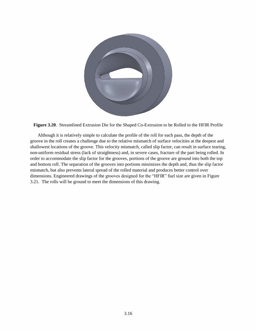
Figure 3.20. Streamlined Extrusion Die for the Shaped Co-Extrusion to be Rolled to the HFIR Profile
Although it is relatively simple to calculate the profile of the roll for each pass, the depth of the
groove in the roll creates a challenge due to the relative mismatch of surface velocities at the deepest and
shallowest locations of the groove. This velocity mismatch, called slip factor, can result in surface tearing,
non-uniform residual stress (lack of straightness) and, in severe cases, fracture of the part being rolled. In
order to accommodate the slip factor for the grooves, portions of the groove are ground into both the top
and bottom roll. The separation of the grooves into portions minimizes the depth and, thus the slip factor
mismatch, but also prevents lateral spread of the rolled material and produces better control over
dimensions. Engineered drawings of the grooves designed for the “HFIR” fuel size are given in Figure
3.21. The rolls will be ground to meet the dimensions of this drawing.
Page 33
3.17
Figure 3.21. Engineered Drawings of the Roll Pockets for Rolling the Shaped Extrusion to the HFIR
Profile
Page 34
4.1
4.0 Discussion
The approach to the development of a co-extruded complex-shaped fuel has been described and an
extrusion of DU-10Mo was made. The extrusion made during FY13 was valuable in process design
because the extrusion forces for the 6:1 extrusion were high and approached the limit for high volume
commercial production. It is important to assess at an early stage the viability of the process to meet the
production demands. Based on the experience of the first extrusion, it is likely that a billet 75 mm in
diameter and approximately 300 mm in length can be extruded to a profile that can be rolled to the HFIR
shape. Such a billet would weigh approximately 26 kg and would produce an extrusion from 900 mm to
1800 mm in length. This extrusion would produce approximately 30 HFIR fuel foils and the extrusion
cycle time for each extrusion would be about 2 minutes. Even at modest productivity, the co-extrusion
process could meet the approximately 3,300-piece fuel plate demand of HFIR in a few days of production
(10). In addition, the canning process would not require the extensive fit-up of the picture frame and
would likely be a simpler process. Therefore from the initial successful extrusion and a simple
calculation, it seems viable to consider co-extrusion as a method for production of the HFIR fuel,
assuming the technical challenges can be overcome.
The technical challenges of the co-extrusion process are being addressed now that a viable extrusion
system has been built and validated. The likely challenges will be the development of a better surface
finish of the U-10Mo to produce uniform Zr thickness and the ability of the Zr-clad extrusion to be rolled
while maintaining Zr integrity. Regarding the first point, this roughness was not unexpected and, in past
experience, has been addressed by billet chemistry, heat treatment and thermomechanical processing; in
fact, in N-Reactor fuels production the variation in clad thickness was a function of billet microstructure,
not of process parameters (6). In order to start to address the roughness issue, the next extrusion will be
homogenized and sleeved in Zr prior to extrusion and then canned in a copper-based alloy. The
homogenization will improve the uniformity of strength by eliminating the hard and soft bands of low and
high Mo content, reducing the bamboo structure, and the Zr sleeve will be stronger than the can and
should prevent the flow of the U-10Mo into the soft can.
The second technical challenge associated with the rolling of the Zr-clad U-10Mo while maintaining
Zr integrity is a difficult step to predict. However, the baseline process for the fuel foil production uses
cold reductions and does not appear to result in unbonding (15). It is reasonable to assume that the shaped
rolling processing would have similar reductions and not cause unbonding.
Although there are limited results, it seems reasonable to assume that the co-extrusion cold rolling
process should be viable as a method to meet the quality and productivity demands of fuel fabrication for
the HFIR. Co-extrusion is not a new process, so many of the technical challenges are only new to the U-
10Mo/Zr co-extrusion.
Page 35
5.1
5.0 Summary
A process path for the production of the HFIR shaped fuel has been identified using co-extrusion for
bonding Zr to U-10Mo and cold shape rolling to achieve final complex shape dimensions. The process
appears to be viable to meet USHPRR fuel fabrication demands for production.
An extrusion system was assembled, installed in a radiologically controlled area and used to
demonstrate the extrusion of a nominal U-10 Mo billet at a reduction ratio of 6:1.
As expected, the force was very high and approached the design limit of the extrusion press. Higher
forces could be used with the PNNL system, but have been restricted to make sure extrusion stresses are
commercially practical.
Suitable lubricants for the extrusion of a canned U-10Mo were identified and demonstrated. Glass
lubricants proved difficult for the small billets with a high surface-area-to-volume ratio and were not
used. To date, no can breaches have occurred and the extrusion system is uncontaminated.
Microstructural examination of the extrusion showed that the extrusion was sound and uniform from
nose to tail, but inhomogeneity of the Mo from the as-cast billet remained after extrusion. The extrusion
process fractured and homogenized the script structure Mo2Si phase but did not fracture the equiaxed
carbides.
The surface of the extrusion after can removal was far too rough for the GTRI fuel tolerances, and
paths forward have been identified and will be implemented in the FY14 test plan. The rough surfaces
will not prevent the ongoing development of the HFIR shape rolling process.
The alloy available for demonstration contained approximately 650, 320 and 260 ppm of Si, C and
Fe, respectively. The levels of Si and Fe likely contributed to the elevated flow stress and high extrusion
forces. This alloy likely will provide a desirable conservatism in the results as the production USHPRR
castings are not likely to have Si levels exhibited in this casting and thus these billets.
Extrusion dies based on the principle of streamlined die design have been designed and fabricated for
the HFIR shaped extrusion. The extrusion pressure for the U-10Mo was very high and, therefore, the dies
designed to produce the HFIR shape were fabricated for ratios of 3:1, 4.5:1 and 6:1. Maximum extrusion
ratio for the HFIR shape will be determined in FY14.
A series of roll grooves have been designed to roll the shaped extrusion to the final dimensions of the
HFIR fuel. The roll grooves were designed for 15% reductions and rolling can be done hot or cold and
will accept the extruded shapes using either 3:1, 4.5:1 or 6:1 reductions.
Page 36
6.1
6.0 References
1. Senor DJ and DE Burkes. 2013. Fuel Fabrication Capability Research and Development Plan.
Global Threat Reduction Initiative – Convert Program, PNNL-22528, Pacific Northwest National
Laboratory, Richland, Washington.
2. Woolstenhulme NE, et al. 2012. Recent Accomplishments in the Irradiation Testing of Engineering-
Scale Monolithic Fuel Specimens. RERTR 2012 – 34th International Meeting on Reduced
Enrichment for research and Test Reactors, Warsaw, Poland.
3. Lewis M, JE Minor and JT Stringer. 1965. Report to Working Committee from Hanford. RL-REA-
1025, Richland, Washington.
4. Taylor LL. 2000. N Reactor (U-metal) Fuel Characteristics for Disposal and Criticality Analysis,
DOE/SNF/REP-056 Rev. 0. Idaho National Engineering and Environmental Laboratory, Idaho Falls,
Idaho.
5. Laue, Kurt* and Helmut Stenger**. 1981. Extrusion. (Copyright in English). Published in U.S. by
American Society for Metals. *Formerly Director of Vereingte Deutsche Metallwerke, Frankfurt.
**Technical Director of Glyco do Brasil Industria Metallurgica, Ltda. Cataguases, Brazil.
6. Lewis M, JE Minor and JT Stringer. 1964. Fuel Development Committee: Annual report from The
General Electric Company, Hanford. Hw-83687, Richland, Washington.
7. Burkes DE, et al. 2009. Update on Fresh Fuel Characterization of U-Mo Alloys. INL/CON-09-
15633, Idaho National Laboratory, Idaho Falls, Idaho.
8. Waldron MB, RC Burnett and SF Pugh. 1955. The mechanical properties of U-Mo alloys. Atomic
Energy Research Establishment (AERE), Harwell, UK. PrePrint 115. Nuclear Engineering Science
and Congress, p. 630, December 1955.
9. Painter CL, DJ Senor, CJ Gesh, BE Schmitt, CA Lavender, KJ Geelhood, AL Doherty and RP
Omberg. 2010. LWR U-Mo Fuel Development Plan. PNNL-19722, Pacific Northwest National
Laboratory, Richland, Washington.
10. Per personal communication with DE Burkes, 2013
11. Gerber M.S., MS. 1993. “Characterization of Mixed Wastes Resulting from Fuel Fabrication at the
Hanford Site: Use of Historical Data,” In: Characterization of Mixed Wastes, p. 549.
http://www.wmsym.org/archives/1993/V1/108.pdf
12. Joshi VV, EA Nyberg, CA Lavender, D Paxton, H Garmestani, DE Burkes. 2013.
“Thermomechanical process optimization of U-10 wt% Mo – Part 1: high-temperature compressive
properties and microstructure.” Journal of Nuclear Materials,
http://dx.doi.org/10.1016/j.jnucmat.2013.10.065.
13. Kaufmann A. et al. 1957. “Uranium Silicon Alloys.” Transactions of the AIME, Journal of Metals,
January 1957, p. 23-27. http://iweb.tms.org/NM/FrP-NM-0710-5.pdf.
14. Srinivasan R et al. 1990. “Extrusion Through Controlled Strain Rate Dies.” J. Mater. Shaping
Technolog. (1990) 8:133-141. http://link.springer.com/article/10.1007/BF02833625#page-1.
15. Moore GA et al. 2009. Monolithic Fuel Fabrication Process Development at the Idaho National
Laboratory. INL/CON-09-17298, Idaho National Laboratory, Idaho Falls, Idaho.
Page 37
PNNL-23045
Distribution
No. of No. of
Copies Copies
Distr.1
1 Department of Energy
National Nuclear Security Administration
Global Threat Reduction Initiative
1000 Independence Ave.
Washington, D.C. 20002-USA
Mr. Christopher Landers
Dr. Natraj Iyer (PDF)
1 Idaho National Laboratory
P.O. Box 1625
Idaho Falls, ID 83415
Mr. Kenneth Rosenberg
Dr. Mitchell Meyer (PDF)
1 Argonne National Laboratory
9700 S. Cass Ave.
Argonne, IL 60439
Dr. John Stevens
6 Local Distribution
Pacific Northwest National Laboratory
D.E. Burkes K8-34
D.M. Paxton K2-03
M.T. Smith K2-03
C.A. Lavender K2-44
V.V. Joshi
A Soulami