Page 1
October 5, 2012
Mitchell Community College
MCC Aerospace Engineering and Technology
http://www.mitchellcc.edu/programs/rocket-projects/index.html
http://www.facebook.com/MCCA.E.T.team
CONCEPTUAL DESIGN REVIEW ROCKSAT-C
ROCKSAT-C 2013 1
Page 2
MCC Aerospace Engineering & Technology
Goal Statement:
The goal of Mitchell Community College’s
aerospace engineering and technology team is to
educate and prepare students for careers based in
science, technology, engineering, or math related
occupations. Through contextual and collaborative
projects, individuals will develop their teamwork and
organizational skills. These projects will foster
innovative thought through hands-on research and
development activities which will lead to improved
opportunities for success in the workforce.
ROCKSAT-C 2013 2
Page 3
ROCKSAT-C 2013 3
Mission Overview
Mission Overview Minimum Success Criteria
Theory and Concepts Concepts of Operations
Mission Requirements Expected Results
Systems Requirements
Conceptual Design Overview
Mechanical Shared Can Logistics
Electrical RockSat-C User’s Guide Compliance
Testing
Management
Team Organization Budget
Mentors Facilities
Schedule Legacy Plan
Conclusions
Page 4
Mission Overview
PEGASIS II
ROCKSAT-C 2013 4
Page 5
Mission Overview
Our goal is to power space-based instrumentation
systems by passively generating energy from transducers
of a proprietary design. Energy will be harvested from the
rocket flight, solar rays, and other sources. This will be
accomplished by building a more robust and simplistic
payload using transducers with increased efficiency and
improved design characteristics. Results may lower cost
and power requirements for space science by reducing the
weight of electrical components.
ROCKSAT-C 2013 5
Page 6
Theory and Concepts:
• Electromagnetic transducers will utilize Faraday’s
Law.
• Solar transducers will utilize Photoelectric effect.
• Peltier coolers will use solar transducer to act as a
heat sink for microprocessors
• Piezoelectric effect
ROCKSAT-C 2013 6
Page 7
Mission Overview
ROCKSAT-C 2013 7
Past Research
• Electrodynamic tethers tested with the Space Shuttle
• MEMS based micro-engineered motion energy harvesting
devices (Imperial College of London, 2007)
• MIDE out of Boston, Ma., founded in 1989, develops
vibration energy harvesting devices
• PEGASIS II is a continuation of our 2012 RockSat-C
Project, PEGASIS.
Page 8
Mission Requirements
Objectives:
• Harvest electrical energy from various sources
during flight.
• Measure various environmental factors
throughout flight such as humidity, magnetic field
and acceleration.
• Use energy harvested to power electronic device
ROCKSAT-C 2013 8
Page 9
Mission Overview
ROCKSAT-C 2013 9
System Requirements
• Energy generators
• Data collection & retention
• Electronic operation control
• Control & experiments (sensing board)
• Simplified structure design
Page 10
Mission Overview
ROCKSAT-C 2013 10
Minimum Success
• Voltages are successfully read from
each transducer and recorded to
memory
• Control sensing board records data of
various environmental aspects
Page 11
Concepts of Operations
ROCKSAT-C 2013 11
Page 12
Expected Results
CONTROL
A sensing board will be powered by a fixed battery. It will
record and save data of different environmental variables.
EXPERIMENT
A sensing board will be powered by energy gathering
devices. The energy used from both sensing boards will be
recorded and saved for comparison. Energy produced by
transducers will also be recorded and saved.
ROCKSAT-C 2013 12
Page 13
Conceptual Design Overview
PEGASIS II
ROCKSAT-C 2013 13
Page 14
Mechanical Design Overview
PEGASIS II
ROCKSAT-C 2013 14
Page 15
Design Overview
ROCKSAT-C 2013 15
Major Components
SUBSYSTEM DEFINITIONS
“EM Pendulum” Magnet suspended on a pendulum over
multiple copper coils will use horizontal
vibrations and angular velocity
“Aubade” Photovoltaic panel
“Jerk” Magnet surrounded by a copper coil will use
vertical vibrations
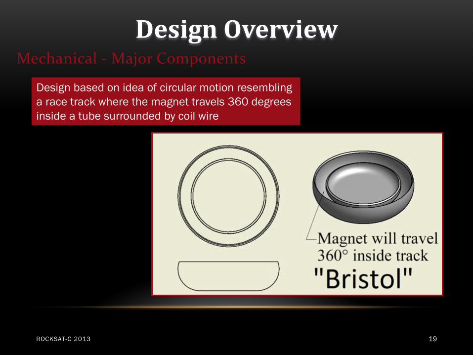
“Bristol” Magnets in a circular track will use angular
velocity
“Diving Board” Piezoelectric cantilever will use horizontal
vibrations
Page 16
Design Overview
ROCKSAT-C 2013 16
Mechanical - Major Components
Will have a pendulum mounted that rotates
with the rocket from the center rotation
surrounded by semispherical wire coils.
Page 17
Design Overview
ROCKSAT-C 2013 17
Mechanical - Major Components
Photovoltaic panel that will be constructed of
efficient solar cells
Solar Rays
N - type
P - type
Junction
Page 18
Design Overview
ROCKSAT-C 2013 18
Mechanical - Major Components
Will create energy through a copper wire coil
wrapped around a cylinder with a magnet
between two springs using the R axis.
Page 19
Design Overview
ROCKSAT-C 2013 19
Mechanical - Major Components
Design based on idea of circular motion resembling
a race track where the magnet travels 360 degrees
inside a tube surrounded by coil wire
Page 20
Design Overview
ROCKSAT-C 2013 20
Mechanical - Major Components
Will vibrate vertically on the z axis of the rocket;
composed of a piezoelectric cantilever
Page 21
Design Overview
ROCKSAT-C 2013 21
Mechanical - Major Components
• Other past transducers will receive further testing for
possible inclusion
• New transducer designs are being considered and will be
tested
• Other producers of energy will be considered for the
payload
Page 22
Design Overview
ROCKSAT-C 2013 22
Mechanical - Structure
• 2 Makrolon Plates, top & bottom
• Circular to match canister
• Components mounted on either the top of the bottom plate or the
bottom of the top plate.
• Aluminum hex standoffs, 4 or 5
• Components made of plastic using rapid prototype or of aluminum
using CNC machines
Page 23
Design Overview
ROCKSAT-C 2013 23
Mechanical - Structure
Green: Electronics Package
•Data Collection
•Data Retention
•Sensing Board (Controlled)
Grey Box: Battery
Grey Cylinder: Jerk
Blue & Red unit: EM Pendulum
Gold: Bristol
Yellow: Aubade
Purple: Diving Board
Pink: Sensing Board (Experiment)
Page 24
Design Overview
ROCKSAT-C 2013 24
Mechanical - Summary
Page 25
Electrical Design Overview
PEGASIS II
ROCKSAT-C 2013 25
Page 26
Design Overview
Electrical - Major Components
• The electrical system will use 1.SYS.1 activation
system at approximately T-5mins.
• An internal counter will begin for further on board
control.
• An Arduino will be used for main processing work and
data acquisition.
• Data will be collected until power is disconnected.
ROCKSAT-C 2013 26
Page 27
Design Overview
Electrical - Major Components
• Sensing board(SB) design form the 2012 mission will
be improved for the 2013 mission.
• Dual SB’s will be used for comparative data.
• One SB will be powered from battery, the control.
• One SB will be powered directly from transducers, the
experiment.
ROCKSAT-C 2013 27
Page 28
Design Overview
Electrical - Major Components
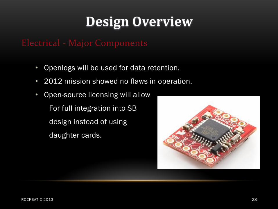
• Openlogs will be used for data retention.
• 2012 mission showed no flaws in operation.
• Open-source licensing will allow
For full integration into SB
design instead of using
daughter cards.
ROCKSAT-C 2013 28
Page 29
Design Overview
ROCKSAT-C 2013 29
Page 30
ROCKSAT-C 2013 30
Transducer
#1
#2 #3
#4
#5
Processor Sensing Board
Control
Battery
Sensing Board
Experiment
Page 31
Design Overview
ROCKSAT-C 2013 31
Electrical - Summary
Page 32
Test Design Overview
PEGASIS II
ROCKSAT-C 2013 32
Page 33
Design Overview
Testing
The goal of our testing plan is to ensure the payload
will perform to design and improve the efficiencies from
Pegasis 2012 transducers. Each test will be used to verify
the payload can withstand high G forces and strong
vibrational forces. Hardware mounts, electrical connectors,
circuit boards and transducers will need to remain
functional after testing.
ROCKSAT-C 2013 33
Page 34
Design Overview
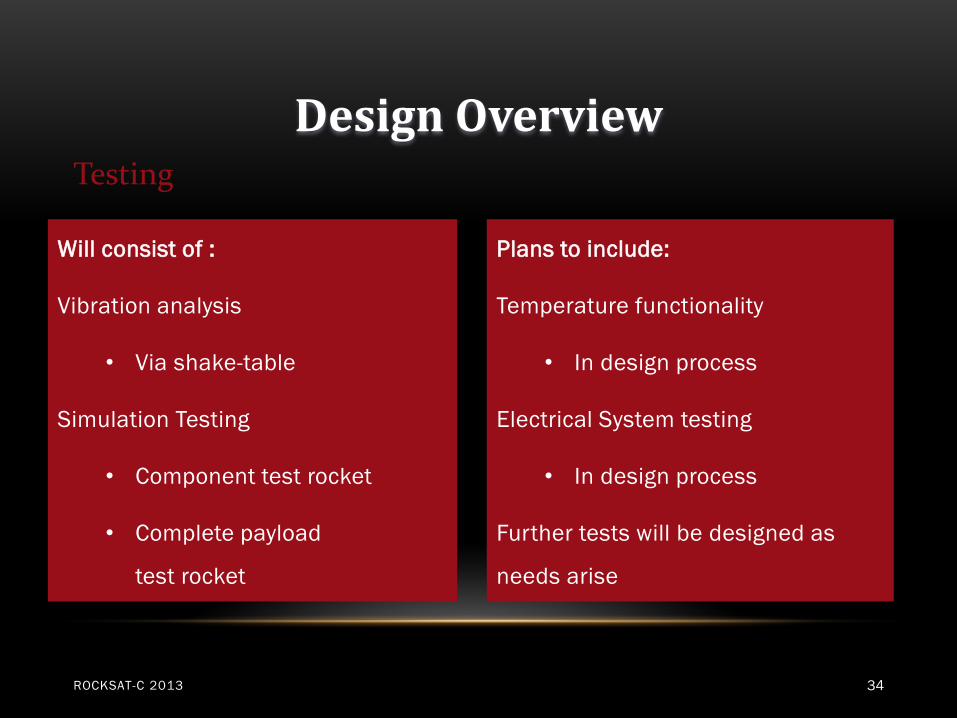
Will consist of :
Vibration analysis
• Via shake-table
Simulation Testing
• Component test rocket
• Complete payload
test rocket
Plans to include:
Temperature functionality
• In design process
Electrical System testing
• In design process
Further tests will be designed as
needs arise
Testing
ROCKSAT-C 2013 34
Page 35
Design Overview
Testing
Shake Table Specs
• Frequency: 200-3000Hz
• 0.1 inch amplitude
• 200-1750 RPM
• Functional spin table: 0-500RPM
ROCKSAT-C 2013 35
Page 36
Design Overview
Testing
Component Rocket Specs
• Length – 42 inches
• Diameter – 4 inches
• Cesaroni – H 400 Motor
• Max Acceleration – 26 (gees) (approx.)
• Max Altitude – 1600 ft (approx.)
• Equipment from last year
ROCKSAT-C 2013 36
Page 37
Design Overview Testing
Full Scale Rocket Specs
•Length – 93 inches
•Diameter – 10 inches
•Cesaroni – J 1520 Motor
•Max Acceleration – 25 (gees) (approx.)
•Max Altitude – 1900 ft (approx.)
•Equipment from last year.
ROCKSAT-C 2013 37
Page 38
Shared can logistics
• Project PEGASIS II will use half a canister and require a partner.
• The optic port will be used, but atmospheric port shall will not be needed.
• Center of mass and all other requirements shall be fulfilled in compliance with RockSat-C 2012-2013 Payload Canister User’s Guide.
• Communication will be done via email
• Solidworks files will be shared with canister partner using Dropbox
• Aluminum hex standoffs will be used to integrate with canister partner
ROCKSAT-C 2013 38
Page 39
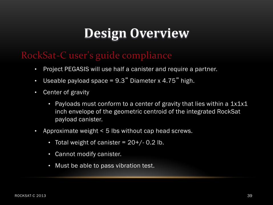
RockSat-C user's guide compliance
• Project PEGASIS will use half a canister and require a partner.
• Useable payload space = 9.3” Diameter x 4.75” high.
• Center of gravity
• Payloads must conform to a center of gravity that lies within a 1x1x1
inch envelope of the geometric centroid of the integrated RockSat
payload canister.
• Approximate weight < 5 lbs without cap head screws.
• Total weight of canister = 20+/- 0.2 lb.
• Cannot modify canister.
• Must be able to pass vibration test.
ROCKSAT-C 2013 39
Page 40
Design Overview
ROCKSAT-C 2013 40
Testing - Summary
Page 41
Management
Pegasis II
ROCKSAT-C 2013 41
Page 42
ROCKSAT-C 2013 42
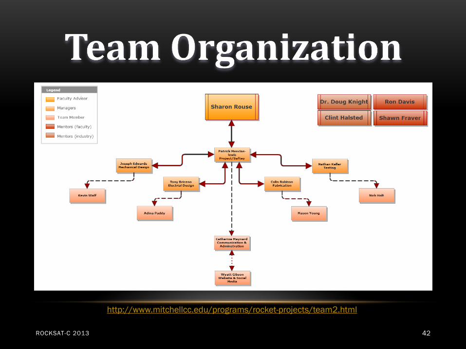
http://www.mitchellcc.edu/programs/rocket-projects/team2.html
Page 43
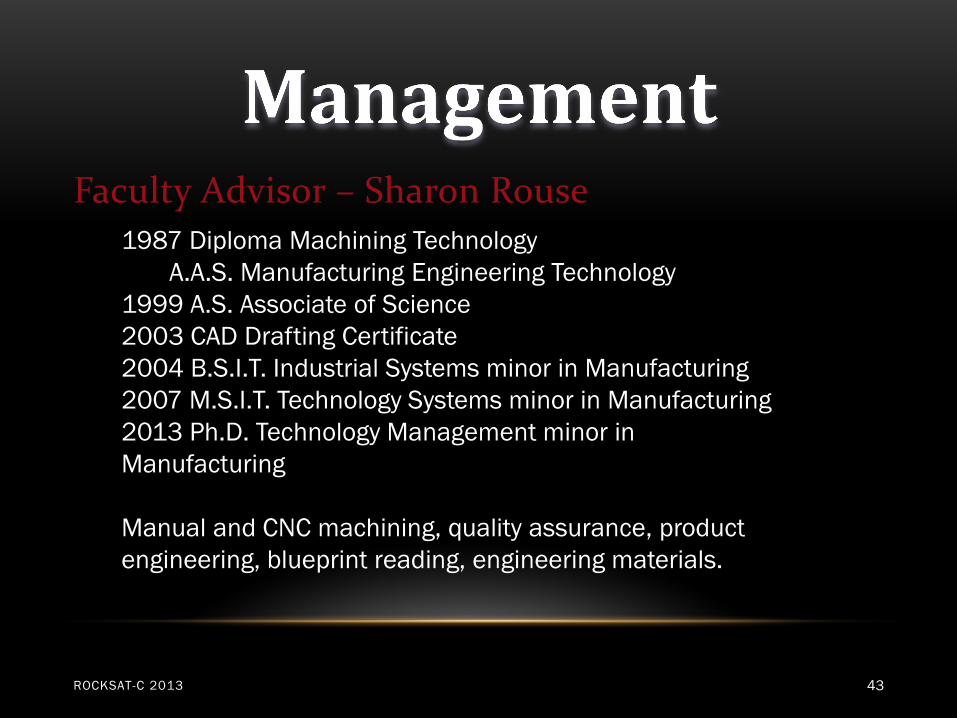
Faculty Advisor – Sharon Rouse
ROCKSAT-C 2013 43
1987 Diploma Machining Technology
A.A.S. Manufacturing Engineering Technology
1999 A.S. Associate of Science
2003 CAD Drafting Certificate
2004 B.S.I.T. Industrial Systems minor in Manufacturing
2007 M.S.I.T. Technology Systems minor in Manufacturing
2013 Ph.D. Technology Management minor in
Manufacturing
Manual and CNC machining, quality assurance, product
engineering, blueprint reading, engineering materials.
Page 44
Management
ROCKSAT-C 2013 44
Doug Knight Ph.D.
Clint Halsted
Shawn Fraver
Ron Davis
Mentors
Page 45
Schedule • 10/8 – RockSat-C meeting
• 10/15– RockSat-C meeting
• 10/17 – Payment and online progress report due
• 10/26-10/27 – PDR and PDR teleconference
• 10/29 – RockSat-C meeting
• 11/1– Small scale test flights begin
• 11/5 – RockSat-C meeting 11/14 – Online progress report due
• 11/18 – RockSat-C meeting
• 11/16 or 11/30 – CDR Due- discuses with team based on finals schedules
• 11/28 – CDR and then CDR teleconference
• 12/3 – RockSat-C meeting, begin legacy equipment testing
• 12/10 – RockSat-C meeting
ROCKSAT-C 2013 45
Page 46
ROCKSAT-C 2013 46
Page 47
Facilities
ROCKSAT-C 2013 47
Electronics Lab
Machine Shop
Rapid Prototyping Printer
Page 48
Management
ROCKSAT-C 2013 48
• A Safety officer will train team members on safe guidelines and
practices.
• A test will be administered to each team member to certify that each
member understands the proper procedure.
• Rocket test flights
• Materials- use non-flammable material.
• Motors- use certified motors.
• We will strictly follow the TRIPOLI HIGH POWER SAFETY CODES.
Safety
Page 49
Management
ROCKSAT-C 2013 49
Legacy Plan
It is a goal of this team to set up a plan to
where new members will join each year and
be taught by experienced members. Also, we
wish to create a long term financial plan to
support the team projects.
Page 50
Further considerations
• Software development
• Selection of transducers
• Individual or group voltage measurement
• Battery selection
• Possible replacement of Arduino with in-house built data
collection device
• Coil design
• Develop test methods as conditions change
ROCKSAT-C 2013 50
Page 51
CONCLUSION
ROCKSAT-C 2013 51
October 5, 2012
Mitchell Community College
MCC Aerospace Engineering and Technology
http://www.mitchellcc.edu/programs/rocket-projects/index.html
http://www.facebook.com/MCCA.E.T.team