52
BGE.COM Conduit construction guide For the installation of conduit, manholes and splice boxes
BGE.COM
Conduit construction guideFor the installation of conduit, manholes and splice boxes

One call to Miss Utility can savetime, money and lives.
Before you pick up any equipment, pick up the phone and call Miss Utility.
Miss Utility will notify all applicable utility companies and see to it that your job site is marked for all underground utility lines. One simple phone call can save you the time
and hassle of dealing with job site mistakes and delays. Not to mention decrease liability, prevent damage, reduce injuries and possibly save lives. After all, safety is everyone’s job.
Call Miss Utility, at least 48 hours prior to work, at 811 or 1.800.257.7777.
Dig Safely CHECKLIST
1. Call Miss Utility at 811 or 1.800.257.7777 at least 48 hours prior to work.2. Allow the required time for utilities to mark the underground lines.3. Respect and protect all marks/flags.4. Excavate with care. Take all reasonable actions to properly protect, support
and backfill underground utility lines.5. Immediately notify the utility if an underground utility line is damaged.6. If damage creates an emergency, take immediate steps to safeguard life,
health and property.
Please check with your individual jurisdictions with regard to waiting times and specific digging guidelines.
For more information, contact Miss Utility or check online at www.missutility.net.
Before you dig, every dig.MISS UTILITY 811 or 1.800.257.7777
It’s the law.

iiiiii
INTRODUCTION
The information in this manual provides general guidelines for the installation of conduit, manholes and splice/pull boxes as it relates to BGE gas and electric service. These guidelines assist developers, general contractors, builders, architects, engineers, licensed electricians and plumbers in the engineering, planning and construction of commercial, industrial and residential projects.
This addendum provides clear and more consistent guidelines on the requirements for conduit and manhole construction. This publication does not cover all the rules and regulations and is to be used in conjunction with the “Commercial, Industrial and Residential Customer Information Booklet”. For your convenience both booklets are available online at bge.com
BGE’s goal is to work with you to install gas and electric service promptly and safely while meeting all construction codes and safety standards. Now and in the future, we’re committed to providing safe and dependable natural gas and electric service.
We hope the information in this manual answers your questions and guides you through the process. If there’s anything we haven’t made clear, please call us at 800.233.1854

TABLE OF CONTENTS
GENERAL Guidelines . . . . . . . . . . . . . . . . . . . . . . . . . . . . . . . . . . . . . . . . . . . . . . . . . . . . . . . . . . . . . . . . . 2Customer responsibilities . . . . . . . . . . . . . . . . . . . . . . . . . . . . . . . . . . . . . . . . . . . . . . . . . . . . . 3
CONDUIT Specifications for Customer Installation . . . . . . . . . . . . . . . . . . . . . . . . . . . . . . . . . . . . . . . . 5–7Standard Duct Bank Arrangement/Installation . . . . . . . . . . . . . . . . . . . . . . . . . . . . . . . . . . . . . . . 8Plastic PVC Duct Spacers General Information . . . . . . . . . . . . . . . . . . . . . . . . . . . . . . . . . . . . . 9Road Crossing Specifications . . . . . . . . . . . . . . . . . . . . . . . . . . . . . . . . . . . . . . . . . . . . . . . . . 103-Phase Transformer Pad Dimensions Detail . . . . . . . . . . . . . . . . . . . . . . . . . . . . . . . . . . . . . 111-Phase Transformer Pad Dimensions Detail . . . . . . . . . . . . . . . . . . . . . . . . . . . . . . . . . . . . . 12Turning Conduit Into Transformer Pads . . . . . . . . . . . . . . . . . . . . . . . . . . . . . . . . . . . . . . . . . 13
SpLICE/pULL BOxESGeneral Information . . . . . . . . . . . . . . . . . . . . . . . . . . . . . . . . . . . . . . . . . . . . . . . . . . . . . . . . . 15Secondary (600V) Fiberglass Splice/Pull Box . . . . . . . . . . . . . . . . . . . . . . . . . . . . . . . . . . . . . 16Installation Instructions for 13 and 34 kV Boxes . . . . . . . . . . . . . . . . . . . . . . . . . . . . . . . . . . . 17Splice/Pull Box - 13kV (#2- 1/0 cables only) . . . . . . . . . . . . . . . . . . . . . . . . . . . . . . . . . . . . . . 18Splice/Pull Box - 13kV (#2- 500 cables only) . . . . . . . . . . . . . . . . . . . . . . . . . . . . . . . . . . . . . . 19Splice/Pull Box - 2-sets 13kV or 1- set 34kV (#2- 750 cables) . . . . . . . . . . . . . . . . . . . . . . 20–21
MANHOLESGeneral Information . . . . . . . . . . . . . . . . . . . . . . . . . . . . . . . . . . . . . . . . . . . . . . . . . . . . . . . . . 23Installation of Precast Concrete Manholes . . . . . . . . . . . . . . . . . . . . . . . . . . . . . . . . . . . . . . . 24Small Secondary Manhole 1 to 4 Services. . . . . . . . . . . . . . . . . . . . . . . . . . . . . . . . . . . . . 25–26Large Secondary Manhole 1 to 7 Services . . . . . . . . . . . . . . . . . . . . . . . . . . . . . . . . . . . . 27–28Precast Concrete Line Manholes . . . . . . . . . . . . . . . . . . . . . . . . . . . . . . . . . . . . . . . . . . . . 29–30Precast Concrete Slotted End Wall Manhole . . . . . . . . . . . . . . . . . . . . . . . . . . . . . . . . . . . 31 –33Installation Standards . . . . . . . . . . . . . . . . . . . . . . . . . . . . . . . . . . . . . . . . . . . . . . . . . . . . 34–40Materials Available from BGE Contractor Supplier . . . . . . . . . . . . . . . . . . . . . . . . . . . . . . . . . . 41
DEFINITIONS AND FREqUENTLy ASkED qUESTIONSDefinitions . . . . . . . . . . . . . . . . . . . . . . . . . . . . . . . . . . . . . . . . . . . . . . . . . . . . . . . . . . . . . . . . . 44Frequently Asked Questions . . . . . . . . . . . . . . . . . . . . . . . . . . . . . . . . . . . . . . . . . . . . . . . . . . 45
1
2
3
4
5

NOTES

1
1
GENERAL

2
1
GUIDELInES
GENERAL
BGE’s Underground Cable SystemsBGE’s underground cable systems are divided into three types:
1. Direct-Buried: (Cables/Gas Pipe installed directly in ground, not installed in any type of duct or sleeve)
This type of system is typically used in rural or suburban areas where:
• Load density is relatively light; a concentration of cables does not exist.• Circuits are not routinely added and front lot line installations.• Dirt digging with occasional paving is expected.• In these areas, the design principle used is loop feed primary and joint trenching with telephone and gas. • Sleeving (short duct lengths) may be used in advance of paving where BGE utilities are to be installed at a
later date (i.e. road crossings, parking lots, etc.).
2. Direct-Buried Conduit: (cables/gas pipe installed in PVC or flex polyethylene duct or sleeve that is installed directly in ground)
This type of system is typically used in rural or suburban areas where special situations exist such as:
• Extensive paved areas with concrete or macadam such as parking lots.• Secondary distribution through paved, limited access, congested or potentially congested areas, thus
preventing easy maintenance digging for repairs or replacement of the installed lines.• Rocky soil conditions which could damage the cable.
(note: Typically used in conjunction with splice/pull boxes and not concrete manholes.)
3. Concrete Encased Conduit: (Cables installed in concrete encased PVC duct)
This type of system is typically used in urban areas where:
• Load density is significant.• Concentration of circuits via the same route are planned or expected.• Additional circuits will be added routinely.• The concentration of circuits, limited Right-of-ways and an expected high number of circuits leaving distribution
or master substations.• Ducts are stacked on top each other.
(note: Typically used in conjunction with concrete manholes and not splice/pull boxes.)(note: Gas sleeves will not be concrete encased.)
3
1GENERAL
General
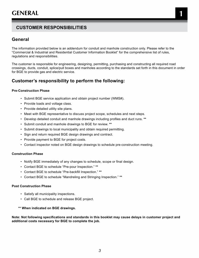
The information provided below is an addendum for conduit and manhole construction only. Please refer to the “Commercial & Industrial and Residential Customer Information Booklet” for the comprehensive list of rules, regulations and responsibilities.
The customer is responsible for engineering, designing, permitting, purchasing and constructing all required road crossings, ducts, conduit, splice/pull boxes and manholes according to the standards set forth in this document in order for BGE to provide gas and electric service.
Customer’s responsibility to perform the following:
Pre-Construction Phase
• Submit BGE service application and obtain project number (WMS#).• Provide loads and voltage class.• Provide detailed utility site plans.• Meet with BGE representative to discuss project scope, schedules and next steps.• Develop detailed conduit and manhole drawings including profiles and duct runs. **• Submit conduit and manhole drawings to BGE for review. **• Submit drawings to local municipality and obtain required permitting.• Sign and return required BGE design drawings and contract.• Provide payment to BGE for project costs.• Contact inspector noted on BGE design drawings to schedule pre-construction meeting.
Construction Phase
• Notify BGE immediately of any changes to schedule, scope or final design.• Contact BGE to schedule “Pre-pour Inspection.” **• Contact BGE to schedule “Pre-backfill Inspection.” **• Contact BGE to schedule “Mandreling and Stringing Inspection.” **
Post Construction Phase
• Satisfy all municipality inspections.• Call BGE to schedule and release BGE project.
** When indicated on BGE drawings.
Note: Not following specifications and standards in this booklet may cause delays in customer project and additional costs necessary for BGE to complete the job.
CUSTOMEr rESPOnSIBILITIES

4
2
CONDUIT

5
2CONDUIT
SPECIfICaTIOnS fOr CUSTOMEr InSTaLLaTIOn
Note: Conduit from the meter termination point to the secondary side of the transformer is the standard method of installation for most three-phase commercial and industrial secondary services. The direct-buried method is still a method of installation where conduit installation would be impractical. When required by BGE, the customer is responsible for designing and building ducts and conduit systems.
Direct-Buried Electric Conduit
Primary and Secondary Electric Conduit
1. Secondary conduit will be 4" minimum inside dimension I.P.S.
2. Primary conduit size varies, contact BGE representative for actual sizes.
3. BGE shall specify the number, size and configuration of ducts.
4. All direct-buried ducts shall be UL schedule 40.
5. All bends shall be no less than 36" in radius. A total of two (2) 90 degree bends are allowed in the conduit line (i.e., conduit turn up at transformer pad is one (1) 90-degree bend). One (1) additional, wide-radius bend (minimum radius of five feet for this additional bend) will be allowed. If this still will not be sufficient for the conduit design/construction, contact your BGE representative. A hand hole, splice/pull box or manhole may be required.
6. The customer shall pull a mandrel (1/2" smaller in diameter than the conduit and 6" long) through each duct prior to BGE cable installation, followed by a pulling line (1800 lb. minimum tensile strength mule line preferred) which shall remain in each duct.
7. Customers will connect all electric conduit with sealed/glue couplings and terminate their conduit with bell ends and plugs.
8. Electrical ducts should be sloped away from the customer's building whenever possible to reduce the potential for water intrusion into the building as a result of failed or missing duct seals.
9. Required depth of conduit from final grade to top of conduit/conduit bank: 30" for secondary, minimum 36" for primary, minimum 48" maximum
10. Backfill evenly around duct with clean dry earth and mechanically tamp in 12" lifts.
11. Lengths of secondary duct banks shall be minimized to limit pulling distances and electrical losses. Any secondary duct lengths over 100 feet shall be approved by BGE prior to construction.
12. The minimum longitudinal separation between foreign structures and conduit should be as follows: Telephone/Cable Television Conduit–3" of concrete or 12" of earth Gas, Water, Sanitary and Oil Mains–12" of earth
13. Splice/pull boxes or manholes may be required by BGE depending on the specific installation.
14. If electric service is being supplied from a new transformer, the customer's duct shall enter the transformer as shown on page titled "Turning Conduit into Transformer Pads" in section two (2) of this booklet.
15. If electric service is being supplied from an existing transformer, the customer shall end the secondary duct five feet from the secondary side of the transformer at a location determined by BGE. BGE will continue the duct into the transformer based on field conditions.
6
2CONDUIT
SPECIfICaTIOnS fOr CUSTOMEr InSTaLLaTIOn (COnT'D)
Direct-Buried Gas Sleeves
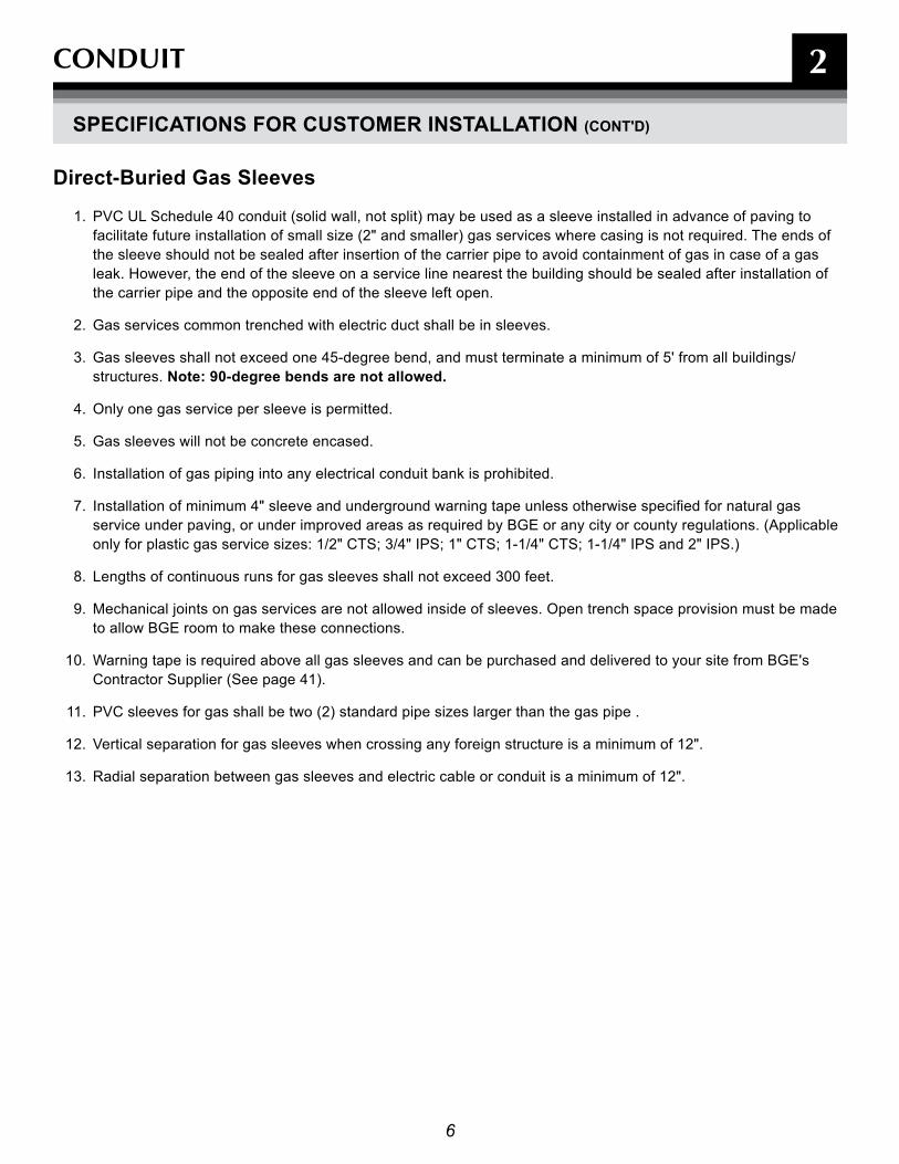
1. PVC UL Schedule 40 conduit (solid wall, not split) may be used as a sleeve installed in advance of paving to facilitate future installation of small size (2" and smaller) gas services where casing is not required. The ends of the sleeve should not be sealed after insertion of the carrier pipe to avoid containment of gas in case of a gas leak. However, the end of the sleeve on a service line nearest the building should be sealed after installation of the carrier pipe and the opposite end of the sleeve left open.
2. Gas services common trenched with electric duct shall be in sleeves.
3. Gas sleeves shall not exceed one 45-degree bend, and must terminate a minimum of 5' from all buildings/structures. note: 90-degree bends are not allowed.
4. Only one gas service per sleeve is permitted.
5. Gas sleeves will not be concrete encased.
6. Installation of gas piping into any electrical conduit bank is prohibited.
7. Installation of minimum 4" sleeve and underground warning tape unless otherwise specified for natural gas service under paving, or under improved areas as required by BGE or any city or county regulations. (Applicable only for plastic gas service sizes: 1/2" CTS; 3/4" IPS; 1" CTS; 1-1/4" CTS; 1-1/4" IPS and 2" IPS.)
8. Lengths of continuous runs for gas sleeves shall not exceed 300 feet.
9. Mechanical joints on gas services are not allowed inside of sleeves. Open trench space provision must be made to allow BGE room to make these connections.
10. Warning tape is required above all gas sleeves and can be purchased and delivered to your site from BGE's Contractor Supplier (See page 41).
11. PVC sleeves for gas shall be two (2) standard pipe sizes larger than the gas pipe .
12. Vertical separation for gas sleeves when crossing any foreign structure is a minimum of 12".
13. Radial separation between gas sleeves and electric cable or conduit is a minimum of 12".

7
2CONDUIT
Concrete Encased Electric Conduit
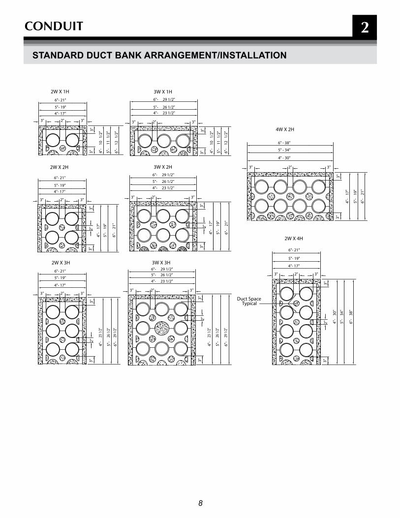
1. Duct banks must be concrete encased if any ducts are stacked vertically (one on top of the other). All 2x2 duct banks and greater must be concrete encased.
2. If ducts are within municipality Right-of-way, it may be required to concrete-encase. Check with local Department of Public Works for specific requirements.
3. BGE shall specify the number, size and configuration of ducts.
4. Schedule 20 PVC must be used for concrete encased ducts.
5. Bends shall be no less than 36” in radius. A total of two (2) 90-degree bends are allowed in the conduit line. If this still will not be sufficient for the conduit design/construction, contact your BGE representative. A manhole, splice/pull box or hand box may be required.
6. Duct spacers that maintain a 2” separation between ducts are required every 6 1/2 - 7'.
Required depth of conduit from final grade to top of conduit/conduit bank (unless otherwise approved by BGE): 30" for secondary, minimum 36" for primary, minimum 48" maximum
7. Only standard 2,500-psi ready-mix concrete with 1/2" pea gravel will be approved for encasement.
8. After concrete cures for 24 hours, backfill around duct bank with clean select soil and mechanically tamp in 8” lifts.
9. The customer shall pull a mandrel (1/2" smaller in diameter than the conduit and 6" long) through each duct prior to BGE cable installation, followed by a pulling line (1800 lb. mule line preferred), which shall remain in each duct.
10. Secondary customer switchgear installations that incorporate metering compartments that are supplied by eight or more ducts, require a pit to be installed under that compartment. The pit shall be 2' deep and measure 1" less than the width and depth of the compartment. Ducts must enter the pit from the bottom, not the sides. Refer to the BGE Gas & Electric Metering Manual under the New Construction Services section available at bge.com for more details.
11. If electric service is being supplied from a new transformer, the customer's duct shall enter the transformer as shown on page titled "Turning Conduit into Transformer Pads" in section two (2) of this booklet.
12. If electric service is being supplied from an existing transformer, the customer shall end the secondary duct five feet from the secondary side of the transformer at a location determined by BGE. BGE will continue the duct into the transformer based on field conditions.
SPECIfICaTIOnS fOr CUSTOMEr InSTaLLaTIOn (COnT'D)
8
CONDUIT 2
4W X 2H
2W X 4H
Duct SpaceTypical
2W X 3H
2W X 2H
2W X 1H
3W X 3H
3W X 2H
3W X 1H
5" - 34"
4" - 30"
6"- 21"
4"- 17"
5"- 19"
3"
3"
26 1/
2"
29 1/
2"
23 1/
2"
3"2"
4"-
5"-
6"-
23 1/
2"
3"
4"-
2"
26 1/
2"
29 1/
2"6"
-
5"-
6"-
5"-
4"-
3"
3"
3"
21"
19"
17"
3"
5"- 19"
6"- 21"
4"- 17"
2"
5"-
3"2"
4"-
6"-
3"
5"- 19"
2"
4"- 17"
6"- 21"
3"
3" 3"2"
4"- 17"
6"- 21"
5"- 19"
1/2"
3"
10
1/2"
1/2"
1211
6"-
5"-
4"-
2" 17"
29 1/2"26 1/2"
23 1/2"
3"
4"-
2"
5"- 6"-
3"
3"
4"-
29 1/2"
26 1/2"
23 1/2"4"-
3" 2"
6"-
5"-
3"3"
3"
21"
19"
6"-
5"-
3" 2"
3" 2"
1/2"
29 1/2"
23 1/2"26 1/2"
4"-
3" 2"
6"-
5"-
3"
10
3"
1/2"
1/2"
11 12 6" - 38"
34"
5"-
3"
4"-
2"
30"
6"-
38"
3"
3"
3"
3"
3"
5"-
19"
4"-
17"
6"-
21"
STanDarD DUCT BanK arranGEMEnT/InSTaLLaTIOn

9
CONDUIT
PLaSTIC PVC DUCT SPaCErS GEnEraL InfOrMaTIOn
Duct Spacers
(A) Duct spacers are used to hold PVC ducts in position and maintain a 2" separation between adjacent ducts while pouring concrete.
(B) There are 3 basic parts to the duct spacers -- the base, intermediate, and cap. If required, there are also pads/feetthat can be used with 5" and 6" spacers for extra supportin an unstable trench bottom.
6.5' to 7'
6.5' to 7'
6.5'to 7'
20' length
(F) To properly support multiple ducts in a trench, the duct spacers are separated approximately6-1/2’ to 7 ‘ apart. Since PVC duct is manufactured in 20’ lengths, this meansthere are three (3) spacers installed within one section of duct.
General Information
(D) Reinforcing bars are used to stabilize theduct and spacers when the concrete ispoured. Drive #4 reinforcing bars through the inside edges of the duct spacers and at least 6" into the trench bottom.
(E) The sides of the trench are used as retainingwalls when the concrete is poured. The distance from the outer duct diameter to the trench wall should be 3" wide. This in turn gives the required 3" apron around the wholeduct bank. Reinforcing bars
driven at least 6"
Final Grade
36" cover for primary30" cover for secondary
into trench bottom
Trench Wall
#4 Reinforcing Bars
3"3"
TrenchWall
(C) Standard cover for a primary conduit system is 36" and30" cover for a secondary conduit system. Both of thesedimensions are measured from �nal grade to the top ofthe concrete envelope of the duct.
Pads
Base
Intermediate
Cap
2
10
2
Final Grade of Road Surface
24” Minimum
49.5” Minimum - 60” Maximum
Electronic Marker
Gas MainConsult BGE if gas main is larger than 2” plastic
Telephone &CATV Cables
PrimaryElectricCable(s)
SecondaryElectricCable(s)
Street Light Cable
Allowance for Rock Bottom
ElectronicMarker
ElectronicMarker
12” 12”
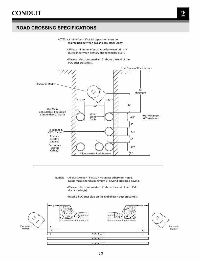
• A minimum 12” radial separation must be maintained between gas and any other utility.
• Allow a minimum 6” separation between primary ducts or between primary and secondary ducts.
• Place an electronic marker 12” above the end of the PVC duct crossing(s).
NOTES:
• All ducts to be 4” PVC SCH 40 unless otherwise noted. Ducts must extend a minimum 5’ beyond proposed paving.
• Place an electronic marker 12” above the end of each PVC duct crossing(s).
• Install a PVC duct plug on the end of each duct crossing(s).
NOTES:
CONDUIT
rOaD CrOSSInG SPECIfICaTIOnS

11
2CONDUIT
3-PHaSE TranSfOrMEr PaD DIMEnSIOn DETaIL/COnDUIT DETaIL
note:
A. The number of secondary 4" conduit shall not exceed 12 total.B. Approximate weight of precast pad is 2200 pounds for 500kVA and smaller transformers (No. 12-668) or 4120
pounds for 750kVA and larger (No. 12-790).C. Customer to install a ½’ x 8’ copper-clad ground rod as required, avoiding in-coming conduit.D. (No. 12-668 & No. 12-790) numbers refer to BGE Material Numbers.E. Pad No.12-790 has two knockouts that allow the 50" opening dimension to be increased to a maximum of 66".F. If the duct count exceeds nine, the ducts shall be banded together within the transformer pad opening to ensure all
ducts remain in their correct spaces within the transformer.G. Transformer pads can be purchased and delivered to your site from BGE's Contractor Supplier (See page 41).H. If electric service is being supplied from an existing transformer, the customer shall end the secondary duct five
feet from the secondary side of the transformer at a location determined by BGE. BGE will continue the duct into the transformer based on field conditions.

12
2CONDUIT
1-PHaSE TranSfOrMEr PaD DIMEnSIOn DETaIL/COnDUIT DETaIL
3
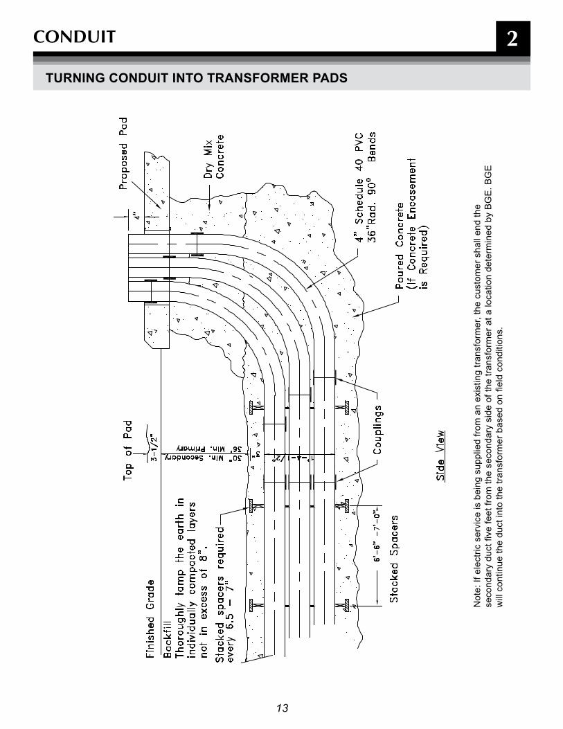
Note: If electric service is being supplied from an existing transformer, the customer shall end the secondary duct five feet from the secondary side of the transformer at a location determined by BGE. BGE will continue the duct into the transformer based on field conditions.
13
2CONDUIT
TUrnInG COnDUIT InTO TranSfOrMEr PaDS
Not
e: If
ele
ctric
ser
vice
is b
eing
sup
plie
d fro
m a
n ex
istin
g tra
nsfo
rmer
, the
cus
tom
er s
hall
end
the
seco
ndar
y du
ct fi
ve fe
et fr
om th
e se
cond
ary
side
of t
he tr
ansf
orm
er a
t a lo
catio
n de
term
ined
by
BG
E. B
GE
w
ill c
ontin
ue th
e du
ct in
to th
e tra
nsfo
rmer
bas
ed o
n fie
ld c
ondi
tions
.
14
3
SpLICE/pULL BOxES

15
3
notes
SpLICE/pULL BOxES
GEnEraL InfOrMaTIOn
Splice/pull boxes are primarily utilized on 13kV or 34kV direct-buried or directional bored polyethylene flex or PVC duct installations. For economic reasons, splice/pull boxes are not intended to be used for direct- buried or concrete encased duct systems. The intent of a splice/pull box is to provide an enclosure in which to install splices or assist in cable pulling operations when duct runs exceed the reel length of a certain cable, or the duct run exceeds the allowed number of bends. Splice/pull boxes can also be used to break into and extend from existing 13kV or 34kV duct systems to maintain the connectivity of the duct system.
Customers must only install BGE approved splice/pull boxes and should consult with a BGE representative prior to design and installation. When required, customers are responsible for purchasing, engineering, designing and constructing all ducts and splice/pull boxes.
There are various sizes and styles of splice/pull boxes. Depending on the specific situations and applications, there are approved splice/pull boxes for 600V, 13kV or 34kV systems and load bearing and non-load bearing applications.
With the exception of the secondary splice/pull box (12-647) all splice/pull boxes are rated for heavy vehicular traffic in parking lots and driveways. They are designed to safely support the weight of occasional, slow moving traffic. They are not rated for frequent, fast moving traffic in street or highway applications.

16
3
24" M
IN.
6"
32"
(Mat'l No. 12-647)Pro�le View
6" Minimum Pea Gravel
Fiberglass Splice/Pull Box
2"
Final Grade
SidewallOpening
6" x 6"
2"
PentaheadBolt
Up to a maximum of six4” diameter ducts canexit the box's extended
NOTE:
opening of 16"W x 10"H
10" 16"
SpLICE/pULL BOxES
SECOnDary (600V) fIBErGLaSS SPLICE/PULL BOx - PEDESTrIan (GraSSy) arEaS OnLy – 1 TO 7 SErVICES
Outside Dimensions: 50"W x 56"L x 32"H, approx. Weight: 100 lb. Mat'l no: 12-647Notes: This fiberglass splice/pull box cannot be used in Baltimore City. For Baltimore City and traffic rated secondary splice/pull boxes see concrete manhole section.
General Information
1. This fiberglass splice/pull box must be installed only in pedestrian (grassy) areas on level ground. It must not be installed on a hill or slope.
2. Stabilize the bottom of the excavation with 6” of pea gravel. The bottom flange of the splice/pull box must be on a firm level foundation.
3. Position the enclosure in the excavation so that the cover will be flush with final grade. See diagram below.
4. Ducts can only enter and exit the splice/pull box at opposite ends from each other. When necessary, the existing 6”x6” openings in the end walls can be enlarged to accommodate multiple ducts (maximum opening 16”W x 10”H). This enlarged opening will allow up to six 4” diameter ducts (3W x 2H configuration) to enter or exit this box. However, only a maximum of eight ducts can be joined to this splice/pull box at any time, one for the secondary main and up to seven for service cables.
5. Install the ducts no more than 2” into the splice/pull box. Use aerosol foam sealer or duct sealing compound around the ducts on the outside of the splice/pull box to seal openings.
6. Place a block of wood over side wall openings without ducts, on the outside, to prevent backfill from entering the confines of the splice/pull box.
7. Once the box and duct are installed, the cover should be securely fastened to the enclosure during backfill compaction. This action will prevent any distortion of the sidewalls while the box is being backfilled.
8. Backfill evenly around the splice/pull box with clean, dry earth and mechanically tamp in 8" layers.
17
3
notes
SpLICE/pULL BOxES
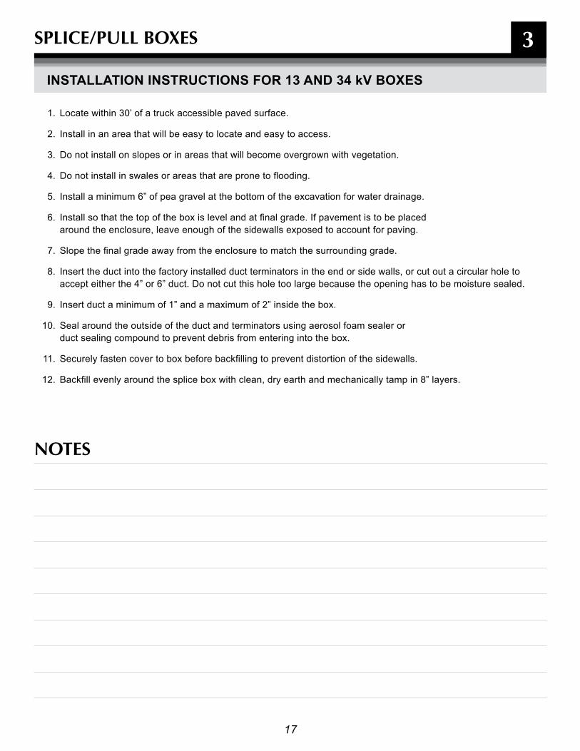
InSTaLLaTIOn InSTrUCTIOnS fOr 13 anD 34 kV BOxES
1. Locate within 30’ of a truck accessible paved surface.
2. Install in an area that will be easy to locate and easy to access.
3. Do not install on slopes or in areas that will become overgrown with vegetation.
4. Do not install in swales or areas that are prone to flooding.
5. Install a minimum 6” of pea gravel at the bottom of the excavation for water drainage.
6. Install so that the top of the box is level and at final grade. If pavement is to be placed around the enclosure, leave enough of the sidewalls exposed to account for paving.
7. Slope the final grade away from the enclosure to match the surrounding grade.
8. Insert the duct into the factory installed duct terminators in the end or side walls, or cut out a circular hole to accept either the 4” or 6” duct. Do not cut this hole too large because the opening has to be moisture sealed.
9. Insert duct a minimum of 1” and a maximum of 2” inside the box.
10. Seal around the outside of the duct and terminators using aerosol foam sealer or duct sealing compound to prevent debris from entering into the box.
11. Securely fasten cover to box before backfilling to prevent distortion of the sidewalls.
12. Backfill evenly around the splice box with clean, dry earth and mechanically tamp in 8” layers.
18
3
Fina
l Gra
deBo
x Co
ver a
t
Plac
e Sp
lice/
Pull
Box
in L
evel
Gro
und
Onl
y
Box
- Pla
n Vi
ew
ELEC
TRIC
Cove
r Han
dles
ELEC
TRIC Li
ftin
g Sl
ing
1/2"
Bol
t for
Two
Piec
e Co
ver
(Min
imum
6" P
ea G
rave
l for
Wat
er D
rain
age)
Box
& C
over
Sec
tion
End
View
36"
64-3
8"
64"
60"
30"
11"
34-1 2
"
34-1 4
"
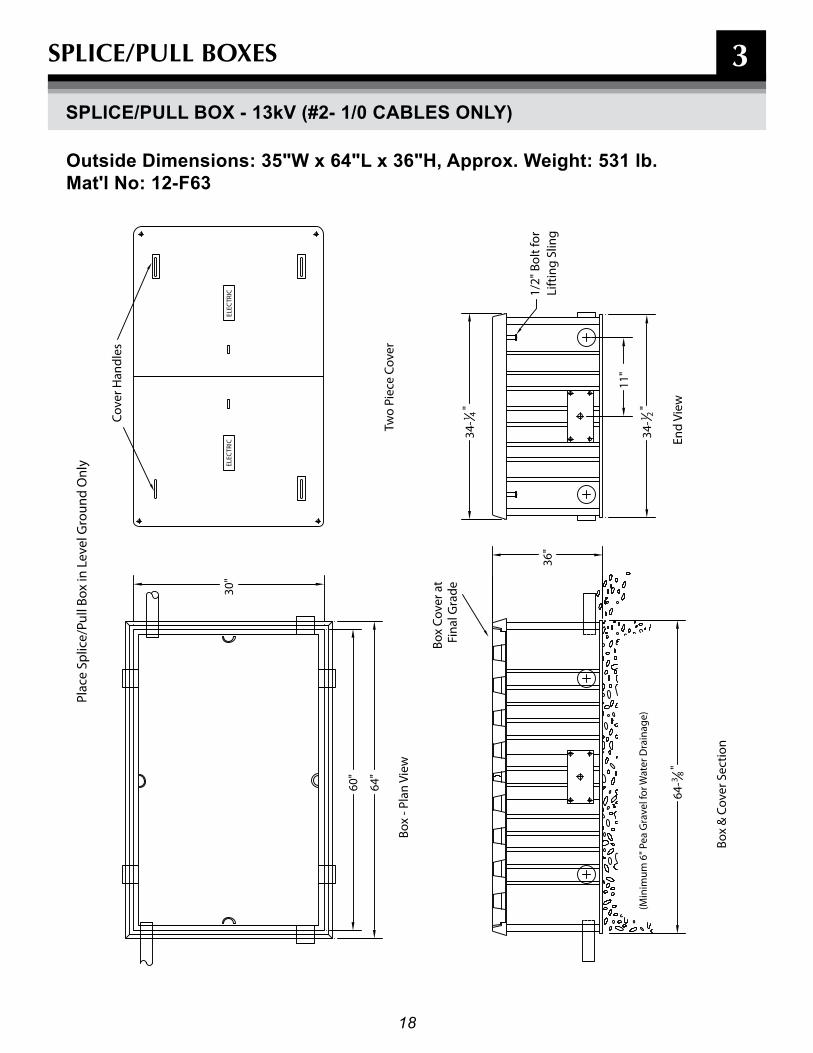
Outside Dimensions: 35"W x 64"L x 36"H, approx. Weight: 531 lb. Mat'l no: 12-f63
SpLICE/pULL BOxES
SPLICE/PULL BOx - 13kV (#2- 1/0 CaBLES OnLy)
19
3
55"
56"
85"
36"
81-3
/4"
86"
51-3
/4"
56"
Box
- Pla
n Vi
ew
(Min
imum
6" P
ea G
rave
l for
Wat
er D
rain
age)
Two
Piec
e Co
ver
Box
& C
over
Sec
tion
End
View
1/2"
Bol
t for
Lift
ing
Slin
g
Plac
e Sp
lice/
Pull
Box
in L
evel
Gro
und
Onl
y
Cove
r Han
dles
Box
Cove
r at
Fina
l Gra
de
ELEC
TRIC
ELECTRIC
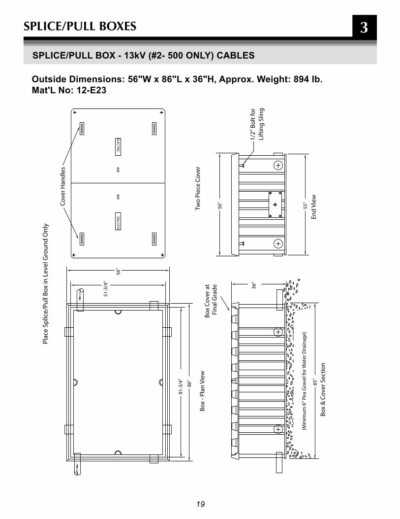
Outside Dimensions: 56"W x 86"L x 36"H, approx. Weight: 894 lb. Mat'L no: 12-E23
SpLICE/pULL BOxES
SPLICE/PULL BOx - 13kV (#2- 500 OnLy) CaBLES
20
3
97-1
/4”
102”
54-1
/4”
54”
2413
22
96-7
/8”
51-5
/8”
Thre
e pi
ece
cove
r
Box
Cov
er a
tFi
nal G
rade
Cov
er H
andl
es
1/2”
Bol
t for
Lifti
ng S
ling
PLAC
E SP
LIC
E/PU
LL B
OX
IN L
EVEL
GR
OU
ND
ON
LY
51-3
/4” 56
”
Box
– Pl
an V
iew
ELEC
TRIC
ELEC
TRIC
ELEC
TRIC
End
View
34”
Box
& C
over
Sec
tion
(Min
imum
6” P
ea G
rave
l for
Wat
er D
rain
age)
64-3
/8”
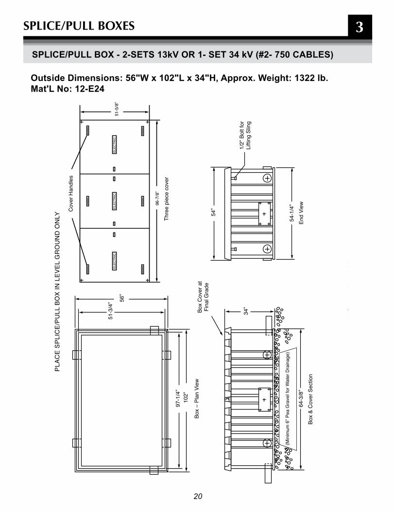
SpLICE/pULL BOxES
SPLICE/PULL BOx - 2-SETS 13kV Or 1- SET 34 kV (#2- 750 CaBLES)
Outside Dimensions: 56"W x 102"L x 34"H, approx. Weight: 1322 lb. Mat'L no: 12-E24

21
3
TOP
VIEW
SpLICE/pULL BOxES
SPLICE/PULL BOx - 2-SETS 13kV Or 1- SET 34kV (#2- 750 CaBLES) (COnT'D)

22
4
MANHOLES

23
4MANHOLES
GEnEraL InfOrMaTIOn
Precast concrete manholes are primarily utilized on 600V, 13kV or 34kV concrete encased conduit systems that require a heavy vehicular traffic rating. The intent of a manhole is to provide a housing in which to install splices or assist in cable pulling operations when duct runs exceed the reel length of a certain cable, or the duct run exceeds the allowed number of bends. Manholes can also be used to break into and extend from existing 13kV or 34kV conduit systems to maintain the connectivity of the system.
Manholes are typically used in urban areas where:
-The concentration of circuits, limited Right-of-way and municipality requirements necessitate the conduit system be in roadways and alleys. -Load density is significant. -Concentration of circuits via the same route are planned or expected. -Additional circuits will be added routinely.
(note: Manholes are typically used in conjunction with concrete encased ducts and not direct-buried PVC)
When required, customers are responsible for engineering, designing, permitting, purchasing, and constructing all ducts and manholes. Customers must purchase manholes from a BGE approved manufacturer. Consult with a BGE representative prior to design and installation for approved list of manufacturers.
Manholes are the most expensive item per foot in conduit construction, so design project to keep the number of manholes to a minimum.
Special Customer requirements for Manhole InstallationsCustomers are required to perform the following for manhole and conduit installations:
• Develop detailed conduit and manhole drawings including profiles and duct runs. ** • Submit conduit and manhole drawings to BGE for review. ** • Submit drawings to local municipality and obtain required permitting.• Contact inspector noted on BGE design drawings to schedule pre-construction meeting. • Contact BGE to schedule “Pre-pour Inspection”. ** • Contact BGE to schedule “Pre-backfill Inspection”. ** • Contact BGE to schedule “Mandreling and Stringing Inspection”. ** • Notify BGE immediately of any changes to schedule, scope or final design.
** When indicated on BGE drawings.

24
4MANHOLES
InSTaLLaTIOn Of PrECaST COnCrETE ManHOLES
The following instructions are to be utilized to install all Precast Concrete Manholes unless otherwise noted. This Section Includes:
• Standard Manholes Sizes • Installation Standards • Duct Terminations• Clearances • Depth (Cover)
Sizes
There are various sizes and styles of BGE approved Precast Concrete Manholes. Depending on the specific situations and applications, manhole types are usually determined by the voltage of the circuits and the proposed number of ducts entering the manhole. Generally your BGE representative will determine the size and type of manhole for your project.
Installation Standards
1. Determine as accurately as possible surface and subsurface obstructions to assure proper installation of manholes and the proper installation, alignment and interception of ducts.
2. Stabilize the bottom of the manhole excavation with 8 " of pea gravel.
3. The excavation bottom shall be dry and level to within 1 " side-to-side and end to end.
4. Position manholes in the excavation so that the rooftop is 1’ minimum – 5’ maximum below final grade. If the manhole has to be installed at a greater than 5’ depth, contact the BGE representative for authorization.
5. Backfill evenly around the manhole with clean, dry earth or sand. Mechanically tamp in 12 " layers.
6. Install 36 frame and cover. Check with local authority for proper cover if the manhole is installed in municipality right of way. On private property a frame and cover can be purchased and delivered to your site from BGE's Contractor Supplier (See page 41) .
7. Place black mastic sealant strips (provided from manufacturer) in the groove on the top of the wall prior to installing top to provide a water tight installation.
Location
1. The preferred manhole location is installed adjacent to, but not in, truck-accessible, H-20 rated roadways to provide access for personnel and construction equipment for the installation and maintenance of manholes, equipment and cables.
2. Second choice, locate manhole to one side of the road (in one traffic lane) and avoid gutter area with manhole cover.
3. Third choice, consider only when necessary. Locate manhole to one side of road (one traffic lane) and avoid gutter area with manhole cover.
4. Locating a manhole in a street intersection is the least desirable alternative because of accessibility and the impact to traffic and underground obstructions.
5. Avoid wet locations, swale areas and low points.
Clearances
1. A minimum of 15' overhead clearance is required for the installation and maintenance of existing and proposed manholes.
2. Maintain 2' minimum horizontal clearance from edge of curb or paving to manhole.
3. Maintain 2' minimum clearance from property line.
4. Minimum horizontal clearance from adjacent buildings is determined by maintaining a one foot horizontal separation for every foot the manhole floor extends below the basement floor elevation.
5. Minimum horizontal clearance from underground obstructions such as retaining walls, pole, foundations is determined by maintaining a one foot horizontal separation for every foot the manhole floor extends below the obstruction.
6. When clearances must be reduced, contact the responsible agency or local authority to negotiate an agreement.
25
4
SMaLL SECOnDary (<600V) ManHOLE 1 TO 4 SErVICES
General Information
1. This manhole can be used in any vehicular traffic area including but not limited to streets, roadways, alleyways,driveways, parking lots and sidewalks.
2. Because of the confined space inside this manhole, only one to four services can be spliced to the secondarymain inside this smaller manhole. (For five to seven services, the larger 6'W x 8'L x 7'H manhole must be used).
3. This 4' x 4' x 4' (inside dimension) manhole must be located on a level area. Do not install it on a hill or slope.
4. Stabilize bottom of excavation with 8" of pea gravel. The bottom shall be dry and level to within 1" side to side.
5. Position the manhole in excavation so that the roof slab is a minimum of 8" below finished grade and the coverends up at final grade.
6. Place black mastic strips (provided with the unit) in groove on top of the wall. Position the 6" concrete roofslab in the groove and compress to provide a watertight installation. See diagram on opposite page.
7. Install 36" frame and cover. Check with local authority for proper cover if the manhole is installed in municipality right of way. On private property a frame and cover can be purchased and delivered to your site from BGE's Contractor Supplier (See page 41).
8. The concrete encased ducts must enter and exit the manhole at opposite ends.
9. Position the ends of the ducts so they are flush with the inside wall.
10. The ducts must enter/exit the manhole 21" from the exterior sided wall and 12" from exterior bottom.
11. A maximum of five ducts can be connected to this manhole at any time, one duct for the secondary main and upto four ducts for the service cables.
12. Backfill evenly around the manhole with clean dry earth and mechanically tamp in 12" layers.
This concrete manhole can be purchased from a.C. Miller Concrete Products Spring City, Pa 19475, Phone 800.229.2922.
MANHOLES

26
Black Mastic
Secondary Main
Knock Out Area
ServiceServiceService
Service
Final Grade
8" Min.12” Max.
5'
5'
6" Pea Gravel
6"
36"
12"
21"
6"
48"
6"
5'
12"
4
note:The concrete encased ducts should enter the manhole 21" from the outside wall where the secondary bus connectors are located. (See diagram above). No more than five ducts shall be connected to this concrete box. One duct is used to install the secondary main. Up to four more ducts can be used for service cables.
SMaLL SECOnDary ManHOLE 1 TO 4 SErVICES (COnT'D)
MANHOLES
Manhole Inside Dimensions = 4’W x 4’L x 4’HOutside Dimensions: 5'W x 5'L x 5'Happrox. Weight: roof 1680 lb., Base 6560 lb.
27
4MANHOLES
LarGE SECOnDary (<600V) ManHOLE 1 TO 7 SErVICES
General Information/Installation instructions
1. Before installing manhole, you must ensure that the exterior top of the manhole is positioned 12" minimum and 5' maximum below final grade. If the manhole is to be installed at a greater depth, contact your BGE representative for approval.
2. This manhole can be used in any vehicular traffic area including but not limited to streets, roadways, alleyways, driveways, parking lots and sidewalks.
3. Because of the confined space inside this manhole, only one to seven services can be spliced to the secondary main inside this manhole.
4. This 6' x 8' x 7' (inside dimension) manhole must be located on a level area. Do not install it on a hill or slope.
5. Stabilize bottom of excavation with 8" of pea gravel. The bottom shall be dry and level to within 1" side to side.
6. Position the manhole in excavation so that the roof slab is a minimum of 12" below finished grade and the cover ends up at final grade.
7. Install the bottom half of the manhole in the excavation. Place black mastic strips (provided with the unit) in groove on top of the wall. Install top half on top of the bottom half and compress to provide a watertight installation.
8. Install 36" frame and cover. Check with local authority for proper cover if the manhole is installed in municipality right of way. On private property a frame and cover can be purchased and delivered to your site from BGE's Contractor Supplier (See page 41).
9. On each end wall of the manhole there are a total of 10-4" end wall duct terminations," six in the bottom half and four in the top half. These terminators are built into the manhole and allow for easier installation of the 4" PVC ducts into the manhole.
10. Install one duct for the secondary main and up to seven ducts for services.
11. Always install ducts in the bottom half of manhole first and leave spare openings in the top half for the future.
12. Backfill evenly around the manhole with clean dry earth. Mechanically tamp in 12" layers.
This concrete manhole can be purchased from a.C. Miller Concrete Products Spring City, Pa 19475, phone: 800.229.2922.

28
4
Bottom Floor Half
Top Roof Half
Six 4" End WallDuct Terminatorsin Bottom Half
in Top HalfWall Duct TerminatorsFour 4" Diameter EndFrame and Cover
36" Openingfor BGE Manhole
Sump
MANHOLE
LarGE SECOnDary ManHOLE 1 TO 7 SErVICES (COnT'D)
Outside Dimensions: 7'W x 9'L x 8'H Manhole Outside Dimensions: 7'W x 9'L x 8'HManhole Inside Dimensions: 6’W x 8’L x 7’Happrox Weight: Top 9200 lb., Bottom 9600 lb.
29
4
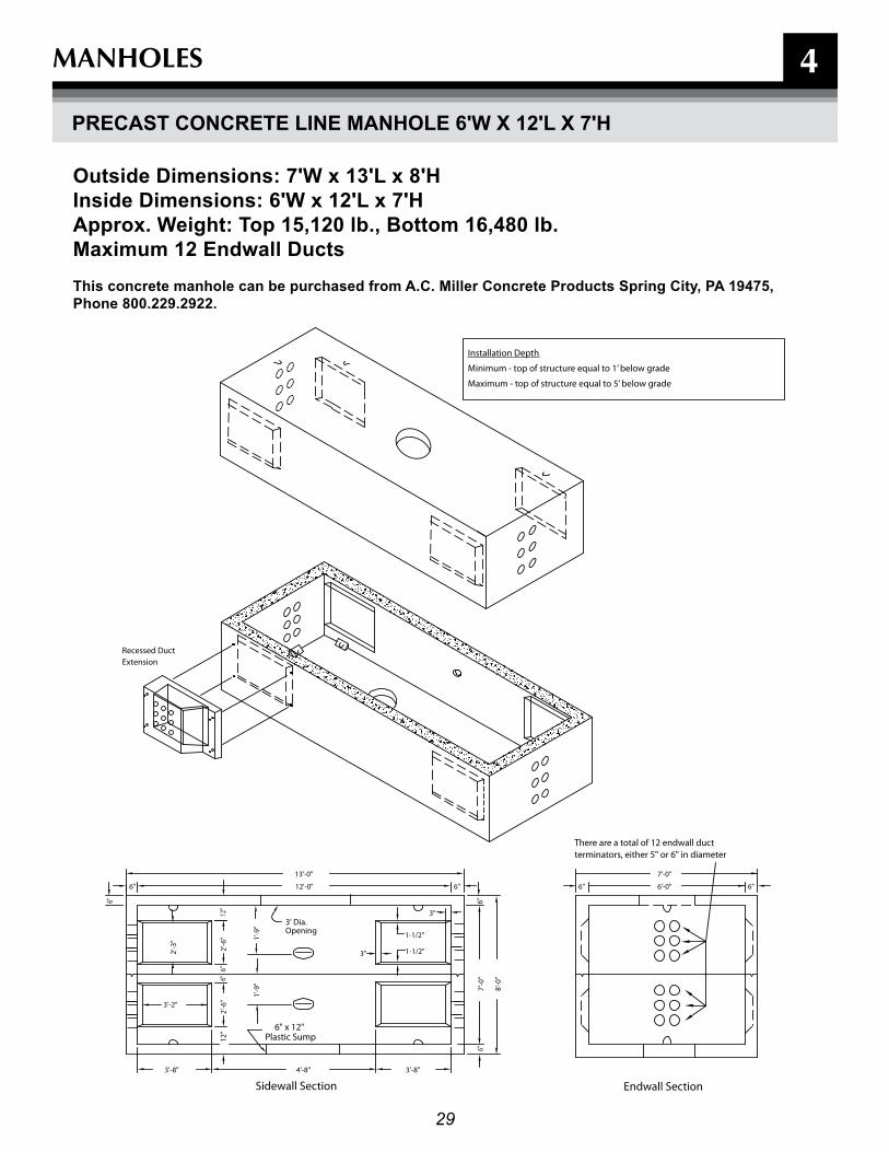
ExtensionRecessed Duct
6"
6"
6"
8'-0
"
7'-0
"
3"
6"
3"
1'-9
"
13'-0"
12'-0"
4'-8"
1'-9
"
3'-8"
1-1/2"
1-1/2"
2'-6
"6"
6"
2'-3
"
12"
6"
6"
12"
3'-2"
3'-8"
2'-6
"
6"6'-0"
7'-0"
3' Dia.Opening
Sidewall Section
Plastic Sump6" x 12"
Endwall Section
terminators, either 5" or 6" in diameter
Minimum - top of structure equal to 1’ below grade
Installation Depth
Maximum - top of structure equal to 5’ below grade
There are a total of 12 endwall duct
PrECaST COnCrETE LInE ManHOLE 6'W x 12'L x 7'H
Outside Dimensions: 7'W x 13'L x 8'HInside Dimensions: 6'W x 12'L x 7'Happrox. Weight: Top 15,120 lb., Bottom 16,480 lb.Maximum 12 Endwall DuctsThis concrete manhole can be purchased from a.C. Miller Concrete Products Spring City, Pa 19475, Phone 800.229.2922.
MANHOLES
30
4
6"7'-0"6'-0"6"
13'- 0"12'- 0" 6"6"
6"
9'-0
"
10'-0
"
6"
3"1-1/2"
3"
3'-8"4'-8"
12"
2'-6
"2'
-0"
1'-0
"
2'-3
"
3'-6
"1'
-6"
6"
12"
3'-8"
6"3'
-6" 3'-2" 2'-6
"
6"
1'-9
"
Opening3' Dia
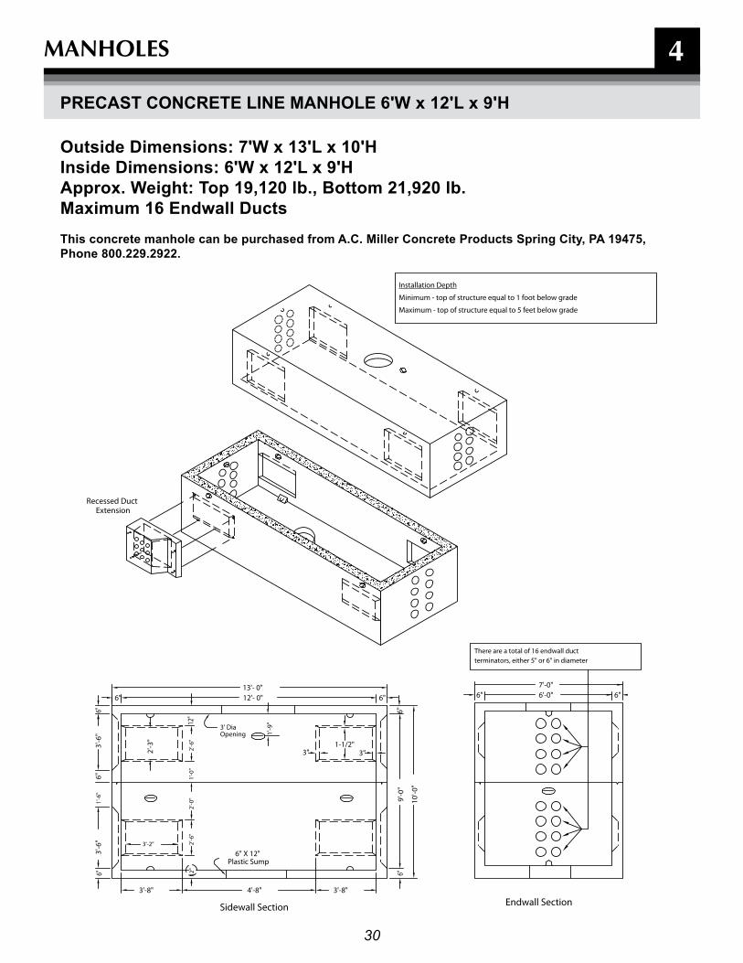
ExtensionRecessed Duct
6" X 12"Plastic Sump
Sidewall Section Endwall Section
There are a total of 16 endwall ductterminators, either 5" or 6" in diameter
Maximum - top of structure equal to 5 feet below grade
Installation Depth
Minimum - top of structure equal to 1 foot below grade
MANHOLES
PrECaST COnCrETE LInE ManHOLE 6'W x 12'L x 9'H
Outside Dimensions: 7'W x 13'L x 10'HInside Dimensions: 6'W x 12'L x 9'Happrox. Weight: Top 19,120 lb., Bottom 21,920 lb.Maximum 16 Endwall DuctsThis concrete manhole can be purchased from a.C. Miller Concrete Products Spring City, Pa 19475, Phone 800.229.2922.
31
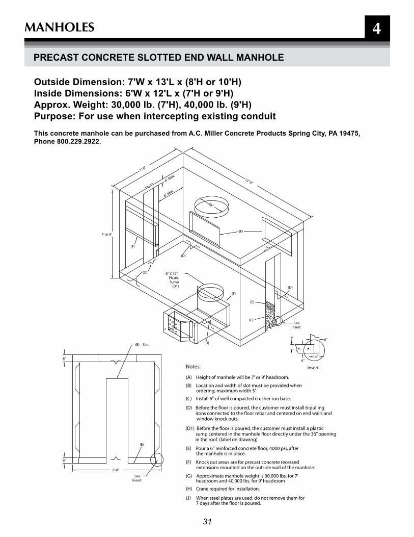
Notes:
(A) Height of manhole will be 7' or 9' headroom.
(B) Location and width of slot must be provided when ordering, maximum width 5'.
(C) Install 6" of well compacted crusher run base.
(E) Pour a 6" reinforced concrete �oor, 4000 psi, after the manhole is in place.
(F) Knock out areas are for precast concrete recessed
(G) Approximate manhole weight is 30,000 lbs. for 7'
(H) Crane required for installation.
(J) When steel plates are used, do not remove them for 7 days after the �oor is poured.
InsertSee
Slot
Insert
InsertSee
SumpPlastic
6" X 12"
(E)
(B)
(F)
(F)
(F)
(C)
(E)
headroom and 40,000 lbs. for 9' headroom
extensions mounted on the outside wall of the manhole.
8"
6"
7'-0"
4"
6"
6"
3"
6" MIN.
6" MIN.
36"
7'-0"
13'-0"
7' or 9'
(D)
(D)
(D1) (D)
(D)
(D) Before the �oor is poured, the customer must install 6-pulling irons connected to the �oor rebar and centered on end walls and window knock outs.
(D1) Before the �oor is poured, the customer must install a plastic sump centered in the manhole �oor directly under the 36” opening in the roof. (label on drawing)
4
Outside Dimension: 7'W x 13'L x (8'H or 10'H)Inside Dimensions: 6'W x 12'L x (7'H or 9'H)approx. Weight: 30,000 lb. (7'H), 40,000 lb. (9'H)Purpose: for use when intercepting existing conduitThis concrete manhole can be purchased from a.C. Miller Concrete Products Spring City, Pa 19475, Phone 800.229.2922.
MANHOLES
PrECaST COnCrETE SLOTTED EnD WaLL ManHOLE

32
4MANHOLES
PrECaST COnCrETE SLOTTED EnD WaLL ManHOLE (COnT'D)
Poured Concrete Floor Reinforcing Bar Detail
Note: Poured floor shall conform to ACI standard 318-71
Precut Rebar and PAI Inserts can be purchased from A.C. Miller Concrete Products, Spring City, PA 19475, phone: 800.229.2922.
MK-F
MK-F
BASE
ManholeWall
MK
-A
MK
-A
6”
36”
72”
3”
12”
MK-AØ 5” O.C. MK-AØ 5” O.C.
MK-K,LØ 3” O.C.
MK-K,LØ 3” O.C.
MK-FØ 12” O.C.
MK-FØ 12” O.C.
MK-MØ 12” O.C. MK-MØ 12” O.C.
Poured-In-Place FloorBill Of Materials:
(1) PAI Sump w/Lid(2) PAI Pulling Irons(1) Bundle Of Precut Non-Epoxy Coated Rebar For Poured-In-Place-Floor(Poured By Customer)
6” Reinforced 4000 PSI Concrete Floor
3”
5/8” Pai Insert
#4 Rebar

33
4MANHOLES
PrECaST COnCrETE SLOTTED EnD WaLL ManHOLE (COnT'D)
Plastic Sump
Pulling Irons
SIDE
TOP
BASE
LID
Rope (ties to lid)
Ø15.23
1-3/4”
1”
9”
27”
Ø13.25
Ø2.00 knock out for optional drainage pipe(pipe by others)
HYTREL TM POLYESTER ELASTOMER PLASTIC COVER BY DUPONT
SEVEN STRAND 1/2” DIA. STEEL CABLE - 270 KIPS (270,000 PSI)
CLIPS CONNECT PULLING IRONTO PA INSERT POCKET
4.03
Lip(locks base into concrete)
Plastic Sump and Pulling Irons can be purchased from A.C. Miller Concrete Products, Spring City, PA 19475, phone: 800.229.29227.
1.00
34
4
SURFACE OBSTRUCTION
PROPOSED END WALLTERMINATIONS
EXISTING DUCT TERMINATIONS IN ADJACENT SIDE WALL
EXISTING END WALLTERMINATIONS
MANHOLE
ZONE 1
ROOF
FLOOR
ENDWALL
SIDEWALL
ZONE 2
ZONE 3
FIG. 1
FIG. 2
2” MIN. SEPARATIONBETWEEN TERMINATIONS 8” MIN.
8” MIN.
MANHOLE WALLS
MANHOLE FLOOR
INSIDE MANHOLE ROOF
MANHOLES
InSTaLLaTIOn STanDarDS
General
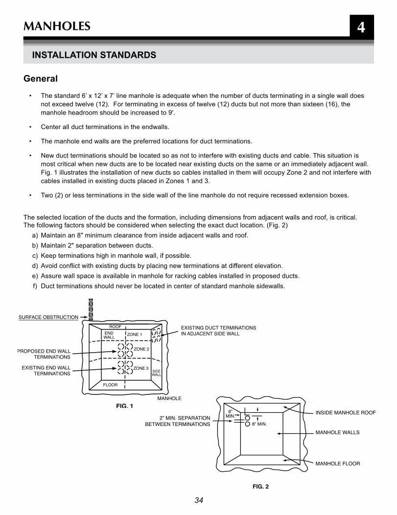
• The standard 6’ x 12’ x 7’ line manhole is adequate when the number of ducts terminating in a single wall does not exceed twelve (12). For terminating in excess of twelve (12) ducts but not more than sixteen (16), the manhole headroom should be increased to 9'.
• Center all duct terminations in the endwalls.
• The manhole end walls are the preferred locations for duct terminations.
• New duct terminations should be located so as not to interfere with existing ducts and cable. This situation is most critical when new ducts are to be located near existing ducts on the same or an immediately adjacent wall. Fig. 1 illustrates the installation of new ducts so cables installed in them will occupy Zone 2 and not interfere with cables installed in existing ducts placed in Zones 1 and 3.
• Two (2) or less terminations in the side wall of the line manhole do not require recessed extension boxes.
The selected location of the ducts and the formation, including dimensions from adjacent walls and roof, is critical. The following factors should be considered when selecting the exact duct location. (Fig. 2)
a) Maintain an 8" minimum clearance from inside adjacent walls and roof. b) Maintain 2" separation between ducts. c) Keep terminations high in manhole wall, if possible.d) Avoid conflict with existing ducts by placing new terminations at different elevation.e) Assure wall space is available in manhole for racking cables installed in proposed ducts.f) Duct terminations should never be located in center of standard manhole sidewalls.

35
4
GRADE
(PROFILE VIEW)
FIG. 1
CONDUIT LINE
AVOID LOCATING MANHOLES IN LOW POINT OF CONDUIT LINE
MANHOLEMANHOLE CONDUIT SYSTEM
(PLAN VIEW)
FIG. 26
STANDARD SECTION LENGTHBETWEEN MANHOLES
850’ FOR 13KV,AND 700’ FOR 34 KV
InSTaLLaTIOn STanDarDS (COnT'D)
Special Lengths
1. Standard distance between manholes must not exceed 850’ for 13kV cables and 700’ for 34kV cables.
2. If conduit design/construction requires spacing to be longer than maximum lengths, contact BGE’s Electric Distribution Engineering and Standards Unit.
MANHOLES
36
(WITH RECESS)PLAN VIEW
FIG. 3
MANHOLE MANHOLECABLE
RECESSSIDEWALL
CABLE SHAPEDQUICKLY TO WALL
(WITHOUT RECESS)PLAN VIEW
FIG. 4
SIDEWALL
(PLAN VIEW)
FIG. 5
SIDEWALL
MANHOLE
TERMINATED DUCTS IN RECESS
PRECAST RECESSED EXTENSION BOXMOUNTED TO OUTSIDE SIDEWALL
END WALL PORTION OF MANHOLEWALL TO BREAK OUT
4
Approx. Weight: 600 lbs.
MANHOLES
InSTaLLaTIOn STanDarDS (COnT'D)
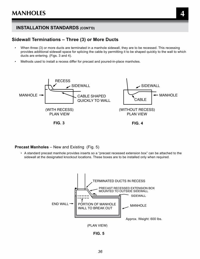
Sidewall Terminations – Three (3) or More Ducts• When three (3) or more ducts are terminated in a manhole sidewall, they are to be recessed. This recessing
provides additional sidewall space for splicing the cable by permitting it to be shaped quickly to the wall to which ducts are entering. (Figs. 3 and 4).
• Methods used to install a recess differ for precast and poured-in-place manholes.
Precast Manholes – New and Existing (Fig. 5)• A standard precast manhole provides inserts so a “precast recessed extension box” can be attached to the
sidewall at the designated knockout locations. These boxes are to be installed only when required.
fIG. 3 fIG. 4
fIG. 5
37
TERMINATED DUCT IN RECESSED EXTENSION
SIDE WALL
END WALL PORTION OF MANHOLE WALL TO BE BROKEN OUT
PRECAST RECESSED EXTENSION BOXMOUNTED TO OUTSIDE WALL
(PLAN VIEW)
FIG. 6
END WALL
SIDEWALL
8 - DUCT TERMINATIONS IN PRECAST RECESSED BOXCENTER DUCT POSITION - NOT TO BE USED 6 - DUCT TERMINATION
(ELEVATION VIEW)
FIG. 7
(ELEVATION VIEW)
FIG. 8
SIDEWALL
END WALL
4
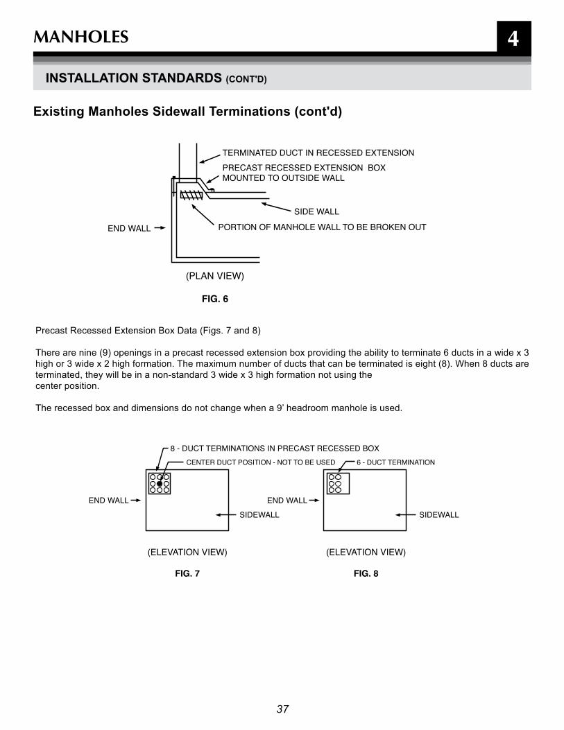
Existing Manholes Sidewall Terminations (cont'd)
Precast Recessed Extension Box Data (Figs. 7 and 8)
There are nine (9) openings in a precast recessed extension box providing the ability to terminate 6 ducts in a wide x 3 high or 3 wide x 2 high formation. The maximum number of ducts that can be terminated is eight (8). When 8 ducts are terminated, they will be in a non-standard 3 wide x 3 high formation not using the center position. The recessed box and dimensions do not change when a 9’ headroom manhole is used.
MANHOLES
InSTaLLaTIOn STanDarDS (COnT'D)

38
4MANHOLES
InSTaLLaTIOn STanDarDS (COnT'D)
recessed Extensions for Precast Manholes Recessed extensions can be purchased from A. C. Miller Concrete Products, Spring City, PA,
phone: 800.229.2922

39
4MANHOLES
InSTaLLaTIOn STanDarDS (COnT'D)
Standard Manhole frame and CoverThis manhole frame and cover can be purchased and delivered to your site from BGE's Contractor Supplier (See page 41). Check with local municipality for proper cover if manhole is located in public right of way.

40
MANHOLES
InSTaLLaTIOn STanDarDS (COnT'D)
Precast Manhole Cover Extension
Various Heights
Various Heights = 3, 6, 9, 12, 15 or 18”
FINAL GRADE
12” MIN. 12” MIN.
FINAL GRADE
PRECAST CHIME36” FRAME & COVER
MANHOLE
4
See A. C. Miller Precast Manholes for Purchasing Information

414141
4MATERIALS
MaTErIaLS aVaILaBLE frOM BGE COnTraCTOr SUPPLIEr
In order to make materials available and as easy as possible for you to obtain, the following materials are available for purchase through BGE’s Contractor supplier:
• Pad, Precast, Concrete 78 In. X 66 In. • Pad, Precast, Concrete 100 In. X 84 In. • Guard, Pipe 4 Inchs Std Galvanized• Guard, Removable Pipe Assembly• Tape, Marking, 3 In. Wide X 1000 Ft. • Cover, Manhole, 36 Inch• Frame, 6" Deep, Roadway, Used With 36'' Dia. Cover• Box, Splice, 15 KV• Box, Splice, 35 KV• Box, Splicing, 600 V, 16''W X 22"L X 30"D• Enclosure, Below Grade 600 V, 12"W X 12''L X 17''D • Enclosure, Below Grade 600 V, 20''w X 30''L X 16''D • Rod Ground• Box, Splice 15kv 30'' X 60'' X 36'' Deep• Pad Plastic Flat 42''x42''x4''• Pad Box 15kv For Pme Air Swgear • Gas Marking Tape
These materials are available by contacting: Choctaw-Kaul Distribution [email protected]
Direct on site delivery.
Variety of payment options are available.
All costs are fully disclosed and are subject to change without notice.

42
NOTES
43
5
DEFINITIONS & FREqUENTLy ASkED qUESTIONS

44
5
Following are definitions for various terms used in this manual and their source or sources where appropriate. Where no reference is provided, the definition given is that which is applicable to BGE’s practices.
BGE - Baltimore Gas & Electric Company or an employee properly qualified to represent Baltimore Gas & Electric Company.
C & I - Commercial & Industrial.
Concrete Encased Duct Bank - Structure consisting of duct(s) spaced at predetermined distance from each other and encased in concrete.
Conduit - A structure containing one or more ducts.
Conduit System - Any combination of duct, conduit, manholes, handholes, and vaults joined to form an integrated whole.
Customer - Any present or prospective user of BGE’s gas or electric service, or any person or entity representing him, such as the architect, engineer, electrical contractor, land developer, builder, etc.
Directional Bore - commonly called horizontal directional drilling, is a steerable trenchless method of installing underground pipes, conduit and cables in a shallow arc along a prescribed bore path by using a surface launched drilling rig.
Direct-Buried - Cables/Gas Pipe installed directly in ground, not installed in any type of duct.
Dry Mix Concrete – One part concrete to two parts gravel that when mixed with four parts water will provide a “Concrete 1-2-4 mix.”
Duct - A single enclosed raceway for conductors or cable.
Duct Coupling - A plastic fitting used to join together two non-belled duct ends.
Duct Terminator - A plastic fitting used to terminate one or more ducts in a manhole or splice/pull box wall.
Mandrel - A device pulled through a duct to ensure the duct has not collapsed, and is clear of debris and usable for cable installation.
Manhole - An underground concrete enclosure to provide housing in which to install cable splices or assist in cable pulling operations.
Preliminary routing Sketch - An engineering plan showing BGE’s proposed route of construction, and transformer and meter locations as drawn on the customer’s site/utility plan.
residential Service - Gas and/or electric service supplied exclusively for domestic purposes in individually metered dwelling units, where permanent residency is established, including the separately metered non-commercial use facilities of a residential customer (e.g., garages, water pumps, etc.).
Secondary Service - Service metered at nominal voltages of 600 volts or less.
Secondary Mains - Mains metered at nominal voltages of 600 volts or less.
Splice/pull box- A subsurface enclosure that is used for the purpose of installing, or maintaining underground cables and splices.
Staked Spacer – A plastic spacer used to hold PVC ducts in position and maintain a 2” separation between adjacent ducts while pouring concrete to encase ducts.
Sump - A pit at the lowest point of a manhole floor into which water is drained in order to be pumped out.
Temporary/Construction Service - A service intended to be used for a limited period, such as for construction, exhibit, or carnival purposes. The temporary facility will be removed at the completion of its use. This may also be referred to as Doubtful Permanency Service.
Transformer - Equipment that converts primary voltage to a lower secondary voltage.
Underground Distribution - A distribution system where the cables and pipes are buried with or without enclosing ducts. Transformers, switches and other equipment are normally above ground, or enclosed in vaults or other enclosures.
UrD (Underground residential Distribution) - An underground distribution system, primarily supplying single-phase, three wire service laterals to residential dwelling units. Most cables are buried. Transformers and primary switches are contained in above ground pad- mounted enclosures
WMS Job number - An identification number assigned to each job in the BGE Work Management System.
DEFINITIONS AND FREqUENTLy ASkED qUESTIONS
DEfInITIOnS
45
5DEFINITIONS AND FREqUENTLy ASkED qUESTIONS
frEqUEnTLy aSKED qUESTIOnS
1. Who is responsible for designing and building the conduit, splice/pull boxes and manholes?• The customer is responsible for engineering,
designing, permitting, purchasing and constructing all road crossings, ducts, conduit, splice/pull boxes and manholes according to the standards set forth in this document.
2. When will BGE require construction, conduit profiles and manhole detail drawings (blow downs)?• At a minimum, BGE will require a detailed site plan
for each project. Depending on the complexity of the project, your BGE representative may require you to provide detailed drawings, including plan views, conduit profiles and manhole blow downs.
3. What size ducts, splice/pull boxes, manholes are required and how many do I need?• BGE will determine the size and number of ducts,
splice/pull boxes or manholes and communicate this information to the customer on a BGE Final Design Plan. Check with the local municipality when installing this material in a public Right-of-way for additional requirements.
4. What is the minimum cover of duct or conduit?• Required minimum cover from final grade to top of
duct or conduit bank:• 30 " for secondary (<600V)• 36 " for primary (>600V)
Note: 48 " maximum depth for top of all duct or conduit unless authorized by BGE representative.
5. What is the minimum cover of a manhole?• Required minimum cover for manholes from final
grade to external top of manhole: - 12 " minimum, 60 " maximum (Excludes
5’x5’x5’ secondary manholes).Note: If requirements call to install manhole below 5’ maximum, contact BGE representative for authorization.
6. Do the ducts need to be stacked or can they be installed side by side?• The preferred method to install four or more parallel
ducts is to stack and concrete encase the duct run. Note: If requirements such as economics and underground obstructions require ducts to be installed side by side, contact BGE representative for authorization.
7. Do I need to have my work inspected by BGE?• All concrete encased duct and manhole installations
will have the following BGE inspections:• Pre-construction • Pre-pour• Pre-backfill • Mandreling and Stringing• Check with local municipalities for additional
requirements* All direct-buried duct, road crossings and splice/pull
boxes will have a BGE pre-site inspection.
8. Where do I purchase splice/pull boxes and manholes?• Splice boxes can be purchased from BGE's
Contractor Supplier (See page 41).• Manholes can be purchased from BGE
approved vendor
9. When do I need to concrete encase my ducts?• Duct banks must be concrete encased if any
ducts are stacked vertically (one on top of the other). All 2x2 duct banks and greater must be concrete encased.
• If ducts are within municipality Right-of-way, it may be required to concrete-encase. Check with local Department of Public Works for specific requirements.
10. Where do I stop the duct if the transformer or pole has not been set?
- Customer is to stop duct 5’ from pole, seal ends of duct and mark location with electronic marker or wooden 2”x 6” stake labeled “BGE”.
11. Is there a means to track my project on the internet?
• Yes…using your BGE WMS or reference number go to “BGE.com” and search:
• “Customer Service” • “Construction Remodeling” • “Check Your Job Status”
12. Who do I contact for conduit questions?
- With questions about conduit and manhole construction refer to this booklet or call your BGE project representative. If you have questions about any of our BGE New Business Services, please contact us on: 800.233.1854.

46
NOTES

47
P.O. Box 1475Baltimore, Maryland 21203


