ICEUBI2019 International Congress on Engineering — Engineering for Evolution Volume 2020 Conference Paper Designing an Eddy Current Brake for Engine Testing Alexandre José Rosa Nunes and Francisco Miguel Ribeiro Proença Brojo University of Beira Interior Abstract An Eddy Current Brake (ECB) has several advantages making it suitable for using in a dynamometer for testing engines. In this paper, a model is presented which considers the electromagnet’s core saturation to predict the performance of an ECB. A design is then proposed for a dual coil, single rotor ECB that meets the design requirement to dissipate a power of 30 kW at 3000 rpm. A comparison between the results obtained for a few different materials considered to be used in the rotating disc are also presented. Keywords: Antimagnetic force, Dynamometer, Eddy current brake, MATLAB Model 1. Introduction When developing a motor, it is necessary to test and characterize its performance for optimization and suitable rating and application. This can be done with a dynamometer by measuring and then drawing the torque and power output curves as well as its efficiency. A dynamometer is a device which absorbs the energy of the motor and measures the force produced therefore allowing to measure its torque and power output when the rotational speed is measured as well. In 1905, Morris presented several different methods to absorb this energy and measure such parameters. [1] Among these, the eddy current brake (ECB) presented itself as a promising device to use as a dynamometer. Wouterse [2] described an ECB, also known as electric retarder, as a machine which dissipates all the mechanically absorbed power as heat in the (thin) disk. It works on the principle that an eddy current is induced around the pole shoe of the coil core when the magnetic flux goes through a rotating conductive disk. The interaction between the magnetic induction and induced currents produce a retarding torque which can, therefore, be used as a brake for determining the torque-speed curves of a motor. This How to cite this article: Alexandre José Rosa Nunes and Francisco Miguel Ribeiro Proença Brojo, (2020), “Designing an Eddy Current Brake for Engine Testing” in International Congress on Engineering — Engineering for Evolution, KnE Engineering, pages 743–756. DOI 10.18502/keg.v5i6.7094 Page 743 Corresponding Author: Alexandre José Rosa Nunes [email protected]Received: 26 November 2019 Accepted: 13 May 2020 Published: 2 June 2020 Publishing services provided by Knowledge E Alexandre José Rosa Nunes and Francisco Miguel Ribeiro Proença Brojo. This article is distributed under the terms of the Creative Commons Attribution License, which permits unrestricted use and redistribution provided that the original author and source are credited. Selection and Peer-review under the responsibility of the ICEUBI2019 Conference Committee.
Transcript
ICEUBI2019International Congress on Engineering — Engineering for EvolutionVolume 2020
Conference Paper
Designing an Eddy Current Brake for EngineTestingAlexandre José Rosa Nunes and Francisco Miguel Ribeiro Proença Brojo
University of Beira Interior
AbstractAn Eddy Current Brake (ECB) has several advantages making it suitable for using in adynamometer for testing engines. In this paper, a model is presented which considersthe electromagnet’s core saturation to predict the performance of an ECB. A design isthen proposed for a dual coil, single rotor ECB that meets the design requirement todissipate a power of 30 kW at 3000 rpm. A comparison between the results obtainedfor a few differentmaterials considered to be used in the rotating disc are also presented.
Keywords: Antimagnetic force, Dynamometer, Eddy current brake, MATLAB Model
1. Introduction
When developing a motor, it is necessary to test and characterize its performance foroptimization and suitable rating and application. This can be done with a dynamometerby measuring and then drawing the torque and power output curves as well as itsefficiency.
A dynamometer is a device which absorbs the energy of the motor and measuresthe force produced therefore allowing to measure its torque and power output whenthe rotational speed is measured as well. In 1905, Morris presented several differentmethods to absorb this energy andmeasure such parameters. [1] Among these, the eddycurrent brake (ECB) presented itself as a promising device to use as a dynamometer.
Wouterse [2] described an ECB, also known as electric retarder, as a machine whichdissipates all the mechanically absorbed power as heat in the (thin) disk. It works on theprinciple that an eddy current is induced around the pole shoe of the coil core whenthe magnetic flux goes through a rotating conductive disk. The interaction betweenthe magnetic induction and induced currents produce a retarding torque which can,therefore, be used as a brake for determining the torque-speed curves of a motor. This
How to cite this article: Alexandre José Rosa Nunes and Francisco Miguel Ribeiro Proença Brojo, (2020), “Designing an Eddy CurrentBrake for Engine Testing” in International Congress on Engineering — Engineering for Evolution, KnE Engineering, pages 743–756.DOI 10.18502/keg.v5i6.7094
method of loading is particularly suitable for testing small motors with a high-speedrange since the entire retarding power is converted into heat. [2–4]
The ECB is widely used in several applications such as making high speed trains lev-itate, setting the different levels of resistance in an exercising bicycle, in dynamometersfor automotive testing and in industrial braking systems. [5]
The advantages of the ECB are: [1–7]
1. Simple and robust;
2. Compact size;
3. Less prone to malfunction as there are no moving parts except for the rotatingdisk;
4. Lack of wear due to no contact between moving components;
5. Noiseless;
6. Lower maintenance costs;
7. Very fast response time;
8. Easy to control;
9. Better performance for both low and high speeds;
10. Uniformity of load after final temperature conditions are reached;
11. Heat produced is not conducted to bearing.
However, it also has some disadvantages such as the braking torque dependingon the magnitude of the magnetic field and the velocity of motion. The first can becontrolled by varying the electric current that passes through the electromagnet andis limited by the coil core saturation whereas the second is directly proportional to thebraking torque available, i.e., the higher the velocity, the higher the braking torque. [5]If the velocity is zero, then so is the braking torque which means it cannot be used forimmobilization.
A typical ECB, in its most basic configuration (Figure 1), consists of an electric conduc-tive disk rotating through a magnetic field which induces eddy currents and produces abraking torque. The eddy currents induce a magnetic field which opposes the originalmagnetic field B.
Three distinct domains can be observed on an ECB at different speeds (Figure 2):[3, 8, 9]
DOI 10.18502/keg.v5i6.7094 Page 744
ICEUBI2019
Figure 1: (a) Configuration of an ECB system; (b) and (c) Cross section of the iron core and disk. [6]
1. Low-speed domain. At these speeds, the magnetic field induced by the eddycurrents is minimal compared to the original magnetic field thus, the magneticinduction B in the air gap is slightly lower than the one at zero speed B0. The brak-ing torque and rotating speed are proportional although this correlation diminishesas the speed increases;
2. Critical-speed domain. In this region, the magnetic field induced by the eddycurrents can no longer be disregarded when compared to 𝐵0 with the magneticinduction B in the air gap being considerably less than B0. The braking torquepeaks at its maximum value and the corresponding speed is taken as the demag-netization or critical speed;
3. High-speed domain. At these speeds, the braking torque becomes inverselyproportional to the rotating speed and shows an asymptotical behavior. In fact,for infinite speed, the induced eddy currents will completely cancel the originalmagnetic field B.
Figure 2: Torque-speed relation on an ECB [3] (left) and B-H curves for four materials (adapted from [10])(right).
DOI 10.18502/keg.v5i6.7094 Page 745
ICEUBI2019
Themagnetic field can be produced by either permanent magnets or electromagnets.Although permanent magnets don’t need any power to produce a magnetic field, itsintensity cannot be controlled. Conversely, electromagnets can quickly change themagnetic field produced by varying the electric current supplied to the coil.
By adding a demagnetized ferromagnetic material to the core of the electromagnet,the external magnetic field H produced by the coil will magnetize this material thereforegreatly increasing themagnetic flux density B produced by the electromagnet. However,there is a limit depending on the material properties after which increasing the magneticfield strength won’t magnetize the core any further and thus the magnetic flux densitywill increase linearly, behaving like an air core. In this case, it is said that the core issaturated.
Figure 2 also shows the correlation between themagnetic field strength andmagneticflux density for four materials often used as ferromagnetic cores and an air core.
1.1. Analytical models for predicting eddy brake performance
Over the years many approaches were taken in trying to develop analytical methodsto predict the eddy currents in a moving conductor, most of which focused on thelow-speed domain.
In 1906, Rudenberg [11] successfully pioneered the study of eddy currents by design-ing a brake energized by direct current with a cylindrical machine as its base. Histheory considered the poles were placed close to each other so sinusoidal functionswere accurate enough to describe both the magnetic fields and current patterns.
Following Rudenberg’s work, Smythe [12] presented a paper in 1942 where thedistribution of the eddy currents induced in a rotating conductive disk around thepole were studied. In his work, Smythe started by modelling the ECB by implyinga magnetic potential theory and then deriving the Maxwell’s equations to describethe demagnetization effects. His work was accurate for the low-speed domain butinaccurate for the high-speed domain.
Continuing Smythe’s work, in 1974 Schieber [13] presented a paper with the sameresults as Smythe but extended the theory to consider the case of a linearly movingstrip, although no work was done regarding the high-speed domain.
In 1991, Wouterse [2] followed the works presented by Smythe and Schieber tovalidate the results previously obtained for the low-speed domain as well as attempt tomodel the eddy currents induced in the high-speed domain.
DOI 10.18502/keg.v5i6.7094 Page 746
ICEUBI2019
Later in 1995, Simeu and George [8] were the first to apply the magnetic circletheory in order to model an ECB. This model calculated the amount of eddy currentsand braking torque by assuming that all the power dissipated by the eddy currentsgenerated braking torque. However, this model did not account for the eddy currentdemagnetization and thus was only suitable for describing the behavior of an ECB inthe low-speed domain.
In 1999, Lee [6] presented work where an ECB and its controller were developedto be used as an alternative to conventional hydraulic brake systems. An approximatetheoretical model was presented to perform a braking torque analysis, which was thenmodified based on experimental results.
Recently, Zhou et al [3] presented in 2015 a paper in which a mathematical modelbased on the magnetic circle theory was developed for an ECB design while introducingthe concept of antimagnetic force. Additionally, simulations based on the model devel-oped were carried out to predict the braking torque characteristics and investigate thefactors that influenced torque generation by variations of the parameters in the ECB’sstructures design. This model showed promising results in predicting the performancefor the low and high-speed domains since it accounted for the influence of both thedemagnetization and temperature effects on the braking torque attenuation.
2. Mathematical Model
The following mathematical model was developed based on the work of Zhou et al. [3]
2.1. Magnetic Circle Theory
The Ampere-Maxwell equation relates the electric currents and magnetic flux as
∮𝑙𝐻 𝑑𝑙 = 𝑁.𝐼 (1)
where l is the equivalent length of the magnetic circle, H is the magnetic field strength,N is the number of turns of the coil and I is the current applied to it. In a singleelectromagnet composed of one core and coil, the path of integration is a closed circleand so ∮𝑙𝐻 𝑑𝑙 = 𝐻.𝑙. The magnetic flux Φ can be calculated by
Φ = 𝐵.𝐴 = 𝜇.𝑁.𝐼.𝐴𝑙 (2)
DOI 10.18502/keg.v5i6.7094 Page 747
ICEUBI2019
where 𝐵 can be calculated by 𝐵 = 𝜇.𝐻 and represents the magnetic flux density, 𝐴 isthe crosssection area of the pole shoe and 𝜇 is the magnetic permeability. The basicmagnetic theory is then described by
Φ = 𝔉ℜ (3)
with 𝔉 = 𝑁.𝐼 and ℜ = 𝑙/(𝜇.𝐴) being defined as the magnetic force and reluctance,respectively. The combined magnetic force 𝔉 is the sum of the magnetic and antimag-netic forces and the overall reluctance ℜ is the overall resistance in electric circles.
2.2. Derivation of the ECB Model
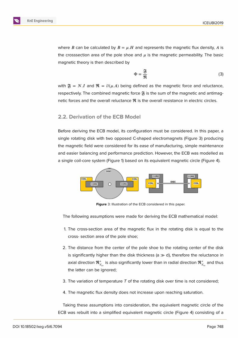
Before deriving the ECB model, its configuration must be considered. In this paper, asingle rotating disk with two opposed C-shaped electromagnets (Figure 3) producingthe magnetic field were considered for its ease of manufacturing, simple maintenanceand easier balancing and performance prediction. However, the ECB was modelled asa single coil-core system (Figure 1) based on its equivalent magnetic circle (Figure 4).
Figure 3: Illustration of the ECB considered in this paper.
The following assumptions were made for deriving the ECB mathematical model:
1. The cross-section area of the magnetic flux in the rotating disk is equal to thecross- section area of the pole shoe;
2. The distance from the center of the pole shoe to the rotating center of the diskis significantly higher than the disk thickness (a ≫ d), therefore the reluctance inaxial direction ℜ∗
𝑑𝑎𝑥 is also significantly lower than in radial direction ℜ∗𝑑𝑟𝑎 and thus
the latter can be ignored;
3. The variation of temperature T of the rotating disk over time is not considered;
4. The magnetic flux density does not increase upon reaching saturation.
Taking these assumptions into consideration, the equivalent magnetic circle of theECB was rebuilt into a simplified equivalent magnetic circle (Figure 4) consisting of a
DOI 10.18502/keg.v5i6.7094 Page 748
ICEUBI2019
magnetic circle with magnetic and antimagnetic forces as well as the air-gap, coil androtating disk magnetic reluctances, connected in series.
The first step was to model the variation of the electric conductivity σ of the rotatingdisk due to the increase in temperature. The electric conductivity σ can be calculatedas
𝜎 = 1𝜌0(1 + 𝛼.𝑇 ) (4)
where 𝜌0 is the electric resistivity of the disk at 20°C, 𝛼 is the temperature coefficient ofresistance and 𝑇 is the temperature of the disk.
Figure 4: Equivalent Magnetic Circle of the ECB (left) and Simplified Equivalent Magnetic Circle of the ECBwith coil, air-gap and disk reluctances (left) (adapted from [3]).
From the Simplified Equivalent Magnetic Circle (Figure 4) and (3), the magnetic fluxin one coilcore can be calculated by
Φ𝑐 =𝔉𝑖 − 𝔉𝑒𝑑𝑑𝑦
ℜ𝑐 +ℜ𝑎 +ℜ𝑑(5)
where 𝔉𝑖 is the magnetic force generated by the applied current in the coil and 𝔉𝑒𝑑𝑑𝑦 isthe defined antimagnetic force produced by the eddy currents induced in the rotatingdisk. The magnetic reluctances of the coil, air-gap and rotating disk areℜ𝑐 ,ℜ𝑎 andℜ𝑑 ,respectively, and can be calculated as
ℜ𝑐 =𝑙𝑐
𝜇𝑐 .𝜇0.𝐴(6)
ℜ𝑎 =𝑙𝑔 − 𝑑𝜇0.𝐴
(7)
ℜ𝑑 =𝑑
𝜇𝑟.𝜇0.𝐴(8)
where l𝑐 is the length of equivalent magnetic circle in the core, 𝜇𝑐 is the relativepermeability of the core, l𝑔 is the distance between the pole shoes, d is the thickness
DOI 10.18502/keg.v5i6.7094 Page 749
ICEUBI2019
of the rotating disk, 𝜇0 is the permeability of vacuum and 𝜇𝑟 is the relative permeabilityof the rotating disk.
The reluctance outside the core ℜ𝑔 can be defined as
ℜ𝑔 = ℜ𝑐 +ℜ𝑎 +ℜ𝑑 (9)
Since the relative permeability of a ferromagnetic core 𝜇𝑐 is several times higher thanthat of the vacuum, with a value of 5000 for iron [14], the reluctance of the core ℜ𝑐
is minimal. It can then be ignored and thus ℜ𝑔 = ℜ𝑎 + ℜ𝑑 . Equation (5) can now berewritten as
Φ𝑐 =𝔉𝑖 − 𝔉𝑒𝑑𝑑𝑦
ℜ𝑔(10)
The magnetic force 𝔉𝑖 can be calculated as
𝔉𝑖 = 𝑁.𝐼 (11)
where N is the number of turns of the coil and I is the current applied to it. Also, basedon Figure 1, the antimagnetic force 𝔉𝑒𝑑𝑑𝑦 generated by the eddy currents induced inthe rotating disk can be calculated by
𝔉𝑒𝑑𝑑𝑦 = ∮𝑠𝐽𝑒𝑑𝑆 = 𝐽𝑒.𝑑.𝑟 (12)
where d is the thickness of the rotating disk, r is the radius of the core’s cross-sectionand J𝑒 is the current density of the eddy currents induced at the center of the pole.These can be calculated by
𝐽𝑒 = 𝜎.𝑎.(𝜔 × 𝐵𝑐) (13)
In (13), a is the distance from the rotating center to the center of the pole shoe area,𝜔 is the angular speed of the rotating disk and B𝑐 is the magnetic flux density in onecoil-core which can be calculated by
𝐵𝑐 =Φ𝑐𝐴 (14)
Considering (12) and (13), the antimagnetic force 𝔉𝑒𝑑𝑑𝑦 can be calculated as
𝔉𝑒𝑑𝑑𝑦 = 𝜎.𝑎.𝑑.𝑟(𝜔 × Φ𝑐𝐴 ) (15)
From (5), 𝔉𝑒𝑑𝑑𝑦 can also be calculated as
𝔉𝑒𝑑𝑑𝑦 = 𝑁.𝐼. − Φ𝑐 .ℜ𝑔 (16)
Hence, from (15) and (16), Φ𝑐 can be calculated as
Φ𝑐 =𝑁.𝐼
ℜ𝑔 + 𝜎.𝑎.𝑑.𝑟.𝜔/𝐴 (17)
DOI 10.18502/keg.v5i6.7094 Page 750
ICEUBI2019
As seen before, the magnetic flux density in one coil-core was taken as𝐵𝑐 = Φ𝑐/𝐴. How-ever, the saturation of the ferromagnetic core was not considered. This was included byhaving 𝐵𝑐 ≤ 𝐵𝑠𝑎𝑡, with B𝑠𝑎𝑡 being the limit of magnetic saturation of the core. Therefore,when the core is not saturated, (13) can be rewritten as
𝐽𝑒 = 𝜎.𝑎.(𝜔 × 𝐵𝑐) = 𝜎.𝑎. (𝜔 × Φ𝑐𝐴 ) (18)
Otherwise, (13) can be rewritten as
𝐽𝑒 = 𝜎.𝑎.(𝜔 × 𝐵𝑠𝑎𝑡) (19)
The total power dissipated by the eddy currents induced by one coil-core can becalculated by integrating 𝜌.𝐽𝑒2 over the cylindrical volume 𝑉𝑐𝑦𝑙 = 𝐴.𝑑. The powerdissipated P𝑑 is then
𝑃𝑑 = 𝜌.𝐽 2𝑒 .𝑉𝑐𝑦𝑙 = 𝜌.𝐽 2
𝑒 .𝐴.𝑑 (20)
The braking torque T𝑏 can simply be calculated by
𝑇𝑏 =𝑃𝑑𝜔 (21)
The critical speed 𝜔𝑐 for which the torque is maximum can be calculated by
𝜔𝑐 =𝑙𝑔 − 𝑑
𝜇0.𝜎.𝑎.𝑑.𝑟+ 𝑑𝜇𝑟.𝜇0.𝜎.𝑎.𝑑.𝑟
(22)
A nonferromagnetic disk has a relative permeability close to that of vacuum, therefore(22) can be simplified to
𝜔𝑐 =𝑙𝑔
𝜇0.𝜎.𝑎.𝑑.𝑟(23)
From the power dissipated and the braking torque of each coil-core, the total powerdissipated and braking torque of the ECB can be calculated by multiplying P𝑑 and T𝑏 ofeach coil-core by the number of coils n𝑐𝑜𝑖𝑙.
2.3. Design requirements for the ECB
The ECB designed in this paper is intended to be applied to a dynamometer in anengine test stand. Consequently, the following design considerations were taken:
1. The material for the rotating disk was chosen to be nonferromagnetic to preventtorsion stresses on the disk;
2. It was decided to use an iron core with a saturation limit of around 2T. [5, 6, 9]However, a saturation limit of 1.5T was considered to account for any materialimpurities, manufacturing errors or further losses in the core;
DOI 10.18502/keg.v5i6.7094 Page 751
ICEUBI2019
3. To prevent coil saturation for the engine’s entire operating domain it was decidedthat the core should not be saturated at angular speeds over 750 rpm since mostsmall engines have idle speeds over this value;
4. It was considered a square shape for the iron core. Compared to a round poleshape, a rectangular pole shape increases the maximum brake torque while keep-ing the critical speed nearly unchanged. Furthermore, the total power dissipationat low and critical speeds is greater for rectangular than for round pole shapes.[14]
5. The main design requirement was a power dissipation of 20kW at 3000rpm dueto the performance of the engine intended to be tested. It is advised to increasethe power dissipation by 35-40 per cent to allow for hysteresis losses and higherharmonics.[4] Consequently, a 50 per cent increase was considered for a powerdissipation of 30 kW at 3000rpm as a requirement for designing the ECB.
2.4. MATLAB Development
The model previously presented was implemented in MATLAB according to theflowchart presented in Figure 5. An iterative process was then followed to find asuitable design that met the design requirements.
The resulting model parameters are defined in Table 1, where b is the side dimensionof the square pole shoe, n𝑐𝑜𝑖𝑙 is the number of coils considered in the simulation and T isthe temperature of the rotating disk. The temperature of the rotating disk was assumedto be 200°C since a forced-air convection cooling system is intended to be installed. InTable 2, the properties of the materials considered for the rotating disk in the simulationare presented. [15–18] The three ferromagnetic materials are for comparison only sincethe material intended to be used is nonferromagnetic.
3. Simulation Results
A maximum angular speed ω𝑚𝑎𝑥 of 6000 rpm was taken as a typical value for an engineat load. After the iterative process the torque, power dissipated and magnetic field fluxdensity curves were obtained and presented in Figure 6.
The maximum torque obtained for the nonferromagnetic materials was 96.41 N.mat a critical speed of 123 rpm for Copper, 99.41 N.m at a critical speed of 188 rpmfor Aluminum and 97.51 N.m at a critical speed of 3369 rpm for Stainless Steel. For
DOI 10.18502/keg.v5i6.7094 Page 752
ICEUBI2019
Figure 5: MATLAB Flowchart.
TABLE 1: Parameters for the ECB Model
Parameter Value Unit
A 150 mm
d 4 mm
b 40 mm
r 22,57 mm
A 1600 mm2
𝜔𝑚𝑎𝑥 6000 rpm
N 3350 -
n𝑐𝑜𝑖𝑙 2 -
l𝑔 7 mm
𝜇0 4𝜋 x 10−7 H/m
T 200 °C
I 3 A
B𝑠𝑎𝑡 1,5 T
the ferromagnetic materials it was 206.35 N.m, 206.30 N.m and 206.37 N.m at criticalspeeds, respectively, of 590 rpm for Iron, 681 rpm for Mild Steel and 2512 rpm forElectrical Steel.
At the design required angular speed of 3000 rpm, the power dissipated calculatedwas 4.60 kW, 6.74 kW and 30.53 kW for Copper, Aluminum and Stainless Steel, respec-tively. As for Iron, Mild Steel and Electrical Steel the results were a power dissipation of25.03 kW, 28.04 kW and 61.17 kW, respectively. Additionally, at the maximum angularspeed of 6000 rpm, a power dissipation of 4.79 kW, 7.15 kW, 56.43 kW, 27.68 kW, 31.46
DOI 10.18502/keg.v5i6.7094 Page 753
ICEUBI2019
TABLE 2: Properties of the Materials for the Rotating Disk
Material Parameter Value Unit
Copper ρ0 1,69 x 10⁻⁸ Ω/m
α 4,30 x 10⁻³ °C−1
μ𝑟 1 -
Aluminium ρ0 2,65 x 10⁻⁸ Ω/m
α 4,50 x 10⁻³ °C−1
μ𝑟 1 -
AusteniticStainless Steel
ρ0 73,00 x 10⁻⁸ Ω/m
α 0,94 x 10⁻³ °C−1
μ𝑟 1,02 -
Iron ρ0 9,70 x 10⁻⁸ Ω/m
α 5,00 x 10⁻³ °C−1
μ𝑟 5000 -
Mild Steel ρ0 14,00 x 10⁻⁸ Ω/m
α 3,00 x 10⁻³ °C−1
μ𝑟 2000 -
Electrical Steel ρ0 59,00 x 10⁻⁸ Ω/m
α 2,00 x 10⁻³ °C−1
μ𝑟 7000 -
Figure 6: Graphical representation of Braking Torque vs Rotating Speed.
kW and 86.36 kW were estimated for Copper, Aluminum, Stainless Steel, Iron, Mild Steeland Electrical Steel, correspondingly. Finally, the core is no longer saturated at angularspeeds of 26 rpm for Copper, 39 rpm for Aluminum and 730 rpm for Stainless Steel,590 rpm for Iron, 682 rpm for Mild Steel and 2513 rpm for Electrical Steel.
DOI 10.18502/keg.v5i6.7094 Page 754
ICEUBI2019
4. Conclusions
This paper presents a MATLAB model that predicts the performance on both low andhigh-speed domains of an ECB to be applied to an engine dynamometer. This model isuseful as a simple tool for predicting the performance of an ECB in a preliminary designprocess.
Following the work of Zhou et al [3], the model developed introduces the electro-magnet core saturation and its impact on the performance, as well as the influence ofusing several different materials for the rotating disk. The first is of utmost importanceto account for the limitation introduced by the material used as the core of the electro-magnet, while the latter is relevant to the speed domain intended to be optimized.
From the results, one can conclude that due to the high speeds achieved by therotating disk, a material with higher electrical resistivity is more adequate since it willincrease the critical speed.
As far as ferromagnetic materials are concerned, only Electrical Steel was able to per-form consistently better than Stainless Steel due to its high resistivity and permeability.However, the coil core remains saturated until an angular speed of 2513 rpm.
Acknowledgments
This work has been supported by the project Centro-01-0145-FEDER-000017 – EmaDeS– Energy, Materials and Sustainable Development, co-financed by the Portugal 2020Program (PT 2020), within the Regional Operational Program of the Center (CENTRO2020) and the European Union through the European Regional Development Fund(ERDF). The authors wish to thank the opportunity and financial support that permittedto carry on this project and C-MAST/ Centre for Mechanical and Aerospace Science andTechnologies.
References
[1] D. K. Morris and G. A. Lister, “The eddy current brake for testing motors”, in Journal
of the Institution of Electrical Engineers, vol. 35, no. 175, pp. 445-468, September1905
[2] J. H. Wouterse, “Critical torque and speed of eddy current brake with widelyseparated soft iron poles”, in IEE Proceedings B – Electric Power Applications, vol.138, no. 4, pp. 153-158, July 1991
DOI 10.18502/keg.v5i6.7094 Page 755
ICEUBI2019
[3] Q. Zhou, X. Guo, G. Tan, X. Shen, Y. Ye and Z. Wang, “Parameter Analysis onTorque Stabilization for the Eddy Current Brake: A Developed Model, Simulation,and Sensitive Analysis”, in Mathematical Problems in Engineering, 2015
[4] D. Gonen and S. Stricker, “Analysis of an Eddy-Current Brake”, in IEEE Transactions
on Power Apparatus and Systems, vol. 84, no. 5, pp. 357-361, May 1995
[5] D. J. T. Cruz, “Design of an Innovative Car Braking System using Eddy Currents”,Master Thesis, University of Victoria, 2005
[6] K. Lee and K. Park, “Optimal robust control of a contactless brake system using aneddy current”, in Mechatronics 9, pp. 615-631, 1999
[7] S. Sharif, J. Faiz and K. Sharif, “Performance analysis of a cylindrical eddy currentbrake”, in IET Electric Power Applications, vol. 6, no. 9, pp. 661-668, November 2012
[8] E. Simeu and D. Georges, “Modeling and control of eddy current brake”, in IFAC
Proceedings Volumes, vol. 28, no. 8, pp. 109-114, July 1995
[9] G. Sokolov, ”Analysis of electrodynamic brake for utilization in systems with rotatingshafts”, Thesis, Saimaa University of Applied Sciences, 2016
[10] J. Bird, ”Electrical Circuit Theory and Technology, Fifth Edition, Bell & Bain Ltd,Glasgow, Great Britain, 2014.
[11] R. Rüdenberg, “Energie der Wirbelströme in elektrischen Bremsen und Dynamo-maschinen”, Enke, 1906
[12] W. R. Smythe, “On eddy currents in a rotating disk”, in Electrical Engineering, vol. 61,no. 9, pp. 681-684, September 1942
[13] D. Schieber, “Braking torque on rotating sheet in stationary magnetic field”, inProceedings of the Institution of Electrical Engineers, vol. 121, no. 2, pp. 117-122,February 1974
[14] M. O. Gulbahce, D. A. Kocabas and F. Nayman, ”Investigation of the effect ofpole shape on braking torque for a low power eddy current brake by finiteelements method,” 2013 8th International Conference on Electrical and Electronics
Engineering (ELECO), Bursa, 2013, pp. 263-267
[15] http://www.nessengr.com/technical-data/resistivity/ (Accessed on 20/03/2019)
[16] J. D. Kraus and K. R. Carver, “Electromagnetics”, International Student Edition, 2ndEdition, McGraw-Hill, 1981
[17] C. Moosbrugger, “ASM Ready Reference: Electrical and Magnetic Properties ofMetals”, ASM International, 2000
[18] J. R. Barnes, “Robust Electronic Design Reference Book”, Volume 2: Appendices,Springer US, 2004