68
Houston, TX June 20, 2012

© 2012 ANSYS, Inc. June 21, 2012 1
Houston, TX June 20, 2012

© 2012 ANSYS, Inc. June 21, 2012 2
Confidence by Design Houston – June 20, 2012
Mike Smocer
Vice President, Central U.S. and Canada

© 2012 ANSYS, Inc. June 21, 2012 3
“How do we manage risk? We calculate it up front in simulation stages at both system
and component levels .”
Scott Parent Vice President of Technology at Baker Hughes,
Oil and Gas Industry Statistics
Global ANSYS Oil and Gas Customer Base
• All super major IOCs
• All oil and gas engineering service companies
• 50 of global top 100 oil and gas companies*
• Design and analysis of all oil/gas equipment
• Over 100+ different applications areas
• Platform for technology evaluation/development *By revenue

© 2012 ANSYS, Inc. June 21, 2012 4
Today’s Mission
The Confidence by Design workshops are designed to help you realize your product promise. The agenda is designed to teach you how to
leverage ANSYS’ tools to ensure that your designs will work the first time, before any prototypes are built and tested.
© 2012 ANSYS, Inc. June 21, 2012 5
Click to edit Master text styles
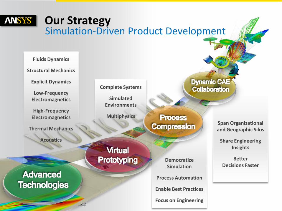
Simulation-Driven Product Development
Democratize Simulation
Process Automation
Enable Best Practices
Focus on Engineering
Complete Systems
Simulated Environments
Multiphysics
Fluids Dynamics
Structural Mechanics
Explicit Dynamics
Low-Frequency Electromagnetics
High-Frequency Electromagnetics
Thermal Mechanics
Acoustics
Span Organizational and Geographic Silos
Share Engineering Insights
Better Decisions Faster
Our Strategy

© 2012 ANSYS, Inc. June 21, 2012 6
Today, product performance is evaluated at the component level. Systems integration occurs at the lab, not on the computer.
Smart Products
What if there was a unified environment that enabled simulation of the complete systems while addressing all relevant components and physics?
Courtesy Baker Hughes

© 2012 ANSYS, Inc. June 21, 2012 7
Smart Products

© 2012 ANSYS, Inc. June 21, 2012 8
Today, design evaluations are done repeatedly (tediously), one physics at a time, to find an “acceptable” design.
Robust Design
What if you could quickly and accurately evaluate multiple designs, at the component and system levels, to pinpoint the best design both for performance and reliability?
Single
Design
Parametric
Simulation
Goal-Driven
Optimization
Probabilistic
Optimization
Courtesy T-Rex Engineering & Construction
Using systems modeling with ANSYS tools enables T-Rex to ensure design robustness of an in-line sled [ILS].
Source: ANSYS Advantage Magazine 2012
Initial Design
Final Design

© 2012 ANSYS, Inc. June 21, 2012 9
Today, analyses are mostly set up and performed by a few experts.
Amplifying Engineering
What if there was a simulation solution that was powerful enough for experts but easy to use and customizable for novices, without compromising on speed, accuracy and scope?
Design change cost
Design change cost
Development phase
Design change cost
ANSYS

© 2012 ANSYS, Inc. June 21, 2012 10
Today, simulation tools are deployed on desktops and sometimes on private, high-performance clusters.
Scalable and Cost-Effective IT Solutions
What if you could deploy simulation across private or public clouds and manage them remotely from a desktop, or even a smart phone or tablet?

© 2012 ANSYS, Inc. June 21, 2012 11
Today, simulations are done by few at a few sites.
Open Collaboration Platform
What if simulation collaboration were limitless (across all departments, geographies and complete systems)?

© 2012 ANSYS, Inc. June 21, 2012 12
Smart Products
Robust Design
Amplify Engineering
Scalable and Cost Effective IT Solutions
Open Collaboration Platform
Conference Guideposts

© 2012 ANSYS, Inc. June 21, 2012 13
Morning Agenda
© 2012 ANSYS, Inc. June 21, 2012 14
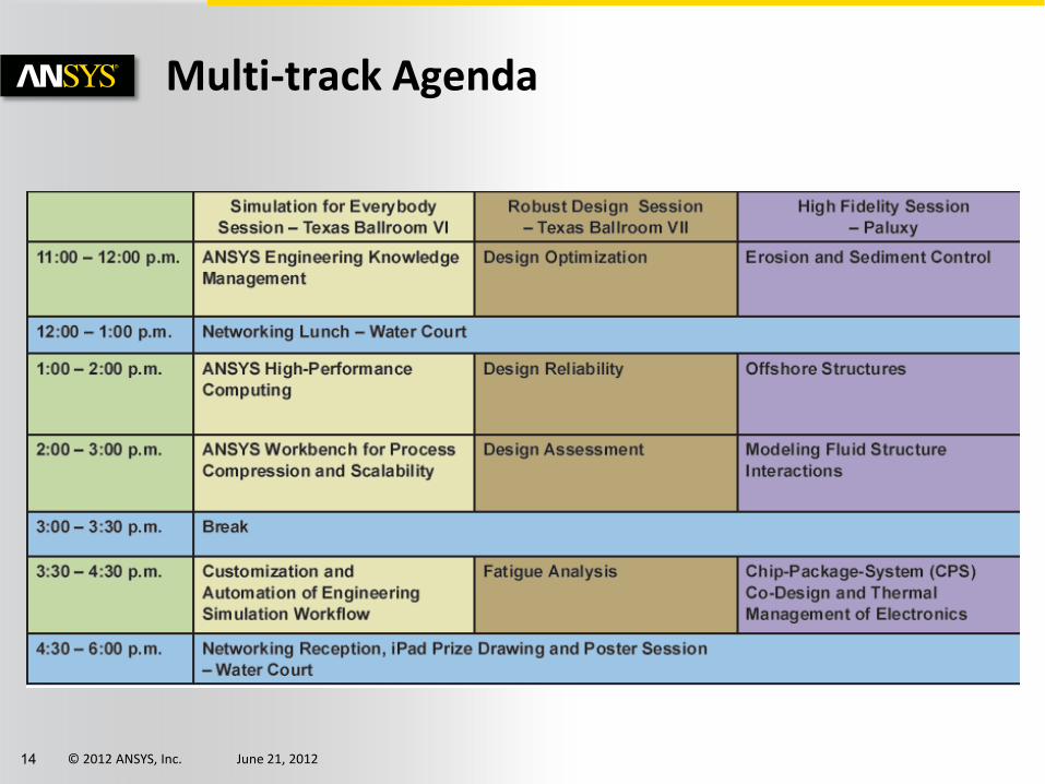
Multi-track Agenda

© 2012 ANSYS, Inc. June 21, 2012 15
Access to these presentations

© 2012 ANSYS, Inc. June 21, 2012 16
Follow us on Social Media
© 2012 ANSYS, Inc. June 21, 2012 17
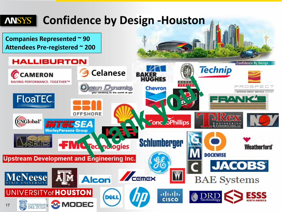
Companies Represented ~ 90 Attendees Pre-registered ~ 200
Confidence by Design -Houston
© 2012 ANSYS, Inc. June 21, 2012 18
“Confidence by Design”
Anirudh M. Technical Services
ANSYS Inc.

© 2012 ANSYS, Inc. June 21, 2012 19
Agenda
Key initiatives that are changing the simulation landscape (yours, ours)
Smart Products
Robust Design
Amplify Engineering
Scalable and Cost Effective IT Solutions
Open Collaboration Platform

© 2012 ANSYS, Inc. June 21, 2012 20
• Which Business drivers & Technology trends will have the greatest impact/influence on
• Process / Product Development Workflow
• Process Optimization / Product Performance Evaluation
Implications for ANSYS product strategy
Priority, Future vision / path to adoption
Key Initiatives
© 2012 ANSYS, Inc. June 21, 2012 21
Key initiatives
Smart Products
Robust Design
Amplify Engineering
Scalable and Cost Effective IT Solutions
Open Collaboration Platform

© 2012 ANSYS, Inc. June 21, 2012 22
• More electronics
• System of systems
1: Systems / Smart Products Products are Increasingly Instrumented and Interconnected
Shift from single to system innovation
ANSYS # 1 Depth & Breadth of Solutions – Your Partner to Enable Systems Approach to Simulation
Crash Sensors; ESP, Sunroof, Seat controls

© 2012 ANSYS, Inc. June 21, 2012 23
Complexity - evaluate product performance at the full system level
Systems
What if there was a unified environment that enabled simulation of the complete systems while addressing all relevant components and physics?
• Effective management (Configurations, reps, model size)
• Different physics environments - Connecting different physics still cumbersome
• High-fidelity (3-D) simulations and reduced-order models simulations can’t be connected easily
Key Challenges Today
© 2012 ANSYS, Inc. June 21, 2012 24
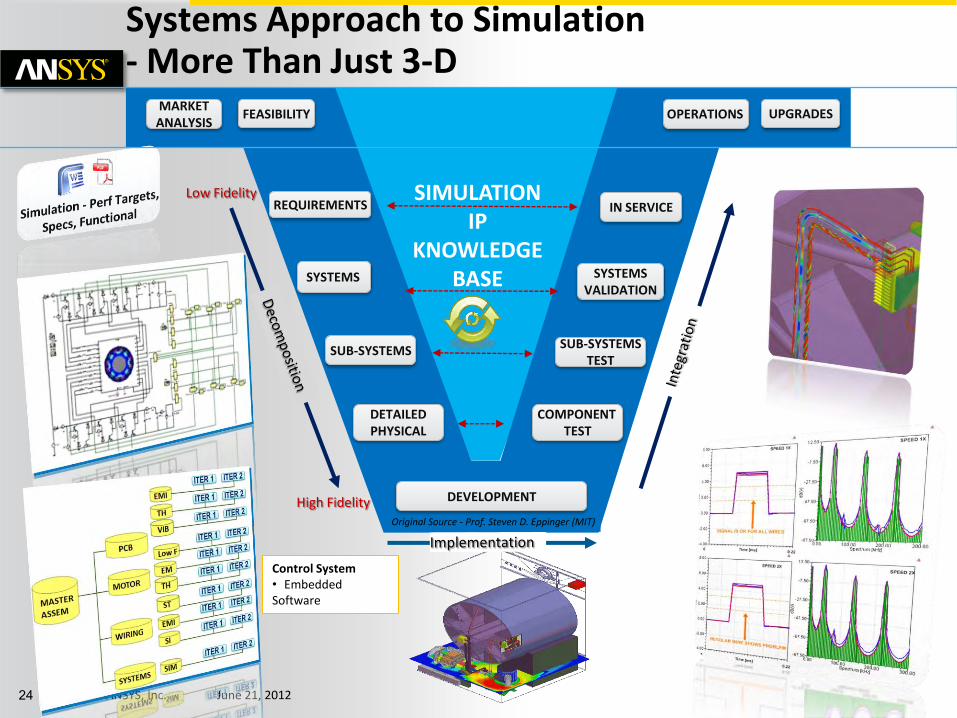
Click to edit Master text styles
MARKET ANALYSIS
FEASIBILITY
REQUIREMENTS
SYSTEMS
SUB-SYSTEMS
DETAILED PHYSICAL
COMPONENT TEST
SUB-SYSTEMS TEST
SYSTEMS VALIDATION
IN SERVICE
OPERATIONS UPGRADES
DEVELOPMENT
SIMULATION IP
KNOWLEDGE BASE
Original Source - Prof. Steven D. Eppinger (MIT)
Low Fidelity
High Fidelity
Control System • Embedded Software
Systems Approach to Simulation - More Than Just 3-D

© 2012 ANSYS, Inc. June 21, 2012 25
Systems – Multiphysics today in WB
Drag-and-drop multiphysics
Automated data transfer and solution mapping
Systems

© 2012 ANSYS, Inc. June 21, 2012 26
Click to edit Master text styles
Water Level
Auxiliary Power Reliability
Core Temperature
Reactor Containment Reliability
Safety of Operation
Variations in operating conditions, manufacturing processes and material properties create uncertainty in the overall success of a product design.
2: Robust Design Methods Building in Product Reliability
Confidence isn’t achieved through the sum of all component validations.
Aids in screening of new product ideas

© 2012 ANSYS, Inc. June 21, 2012 27
The Path to Robust Design
Single Physics Solution
•Accuracy, robustness, speed…
Multiphysics Solution
•Integration Platform
“What if” Study
•Parametric Platform
Design Exploration
•DOE, Response Surfaces, Correlation, Sensitivity, etc.
Optimization
•Algorithms
Robust Design
•Probabilistic Algorithms
Key Enablers/Dependencies - User Experience - IT Scalability & Licensing - Data Management - Process Automation

© 2012 ANSYS, Inc. June 21, 2012 28
• Determining the right parameters over a large number of combinations of design and environmental factors.
• Computational costs & Licensing
• Specialized tools and processes are needed for a full system level study – Not easy across domains
Key Challenges Today
What if you could accurately evaluate multiple designs with a set of easy to use process automation & optimization tools while addressing the bottlenecks with IT and big data.
Single
Design
Parametric
Simulation
Goal-Driven
Optimization
Probabilistic
Optimization
Robust Design

© 2012 ANSYS, Inc. June 21, 2012 29
• Parameters defined in the applications; managed at the project level
• Rapid what-if studies
Workbench Platform Parametric Studies
Robust Design

© 2012 ANSYS, Inc. June 21, 2012 30
• Drive parametric simulation with ANSYS DesignXplorer
• Easily advance from one-off simulation to DOE and optimization studies
• Gain dramatically more design insight with little additional engineering time
Workbench Platform, Integrated Optimization
Robust Design

© 2012 ANSYS, Inc. June 21, 2012 31
Click to edit Master text styles
• Pervasiveness of CAE – “Front Loading”
• Intense pressure – Do more with less
• New product development initiatives call for improved methodologies and tools
• Human Capital and Consistency challenges
• Amplify Existing Engineers’ Productivity and Scope
• Democratize Simulation to the Engineering Masses
3: “Amplifying” Engineering New Simulation Users, More Productive Users
© 2012 ANSYS, Inc. June 21, 2012 32
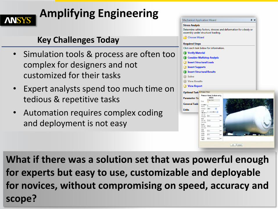
Amplifying Engineering
What if there was a solution set that was powerful enough for experts but easy to use, customizable and deployable for novices, without compromising on speed, accuracy and scope?
• Simulation tools & process are often too complex for designers and not customized for their tasks
• Expert analysts spend too much time on tedious & repetitive tasks
• Automation requires complex coding and deployment is not easy
Key Challenges Today

© 2012 ANSYS, Inc. June 21, 2012 33
Workbench Platform Automation and Re-use
Illustration: ► Change the geometry ► Update the project ► Entire project updates in batch mode
Amplify
Engineering
© 2012 ANSYS, Inc. June 21, 2012 34
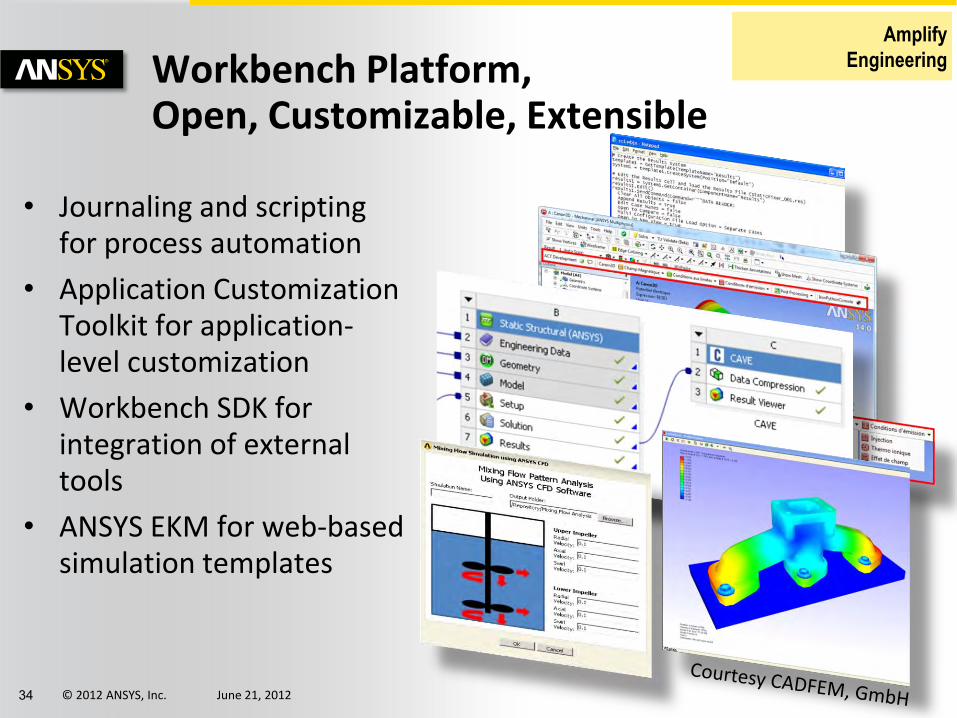
• Journaling and scripting for process automation
• Application Customization Toolkit for application-level customization
• Workbench SDK for integration of external tools
• ANSYS EKM for web-based simulation templates
Workbench Platform, Open, Customizable, Extensible
Amplify
Engineering

© 2012 ANSYS, Inc. June 21, 2012 35
Up Front Analysis Drives Productivity
Business Initiative: Analysis Led Design Cummins Analysis Led Design (ALD) strategy is a corporate-wide initiative to change the prevalent test-first culture
Significant benefits include:
• shorter development time,
• lower costs and
• improved products.
ALD can shorten product development time by getting designs right the first time.
“The idea is to place simplified analysis tools in the hands of our designers so they can make more intelligent decisions. Preliminary screening is done early, allowing for domain experts to spend more time on those design enhancements that are shown to hold the greatest promise.”
Francois Ntone Senior Technical Advisor, CEFD Cummins, Inc.
Amplify
Engineering

© 2012 ANSYS, Inc. June 21, 2012 36
“By embedding ANSYS technology in our engineering curriculum, Cornell is producing
students who can go into industry with a strong foundation in the application of
advanced simulation.”
Professor Rajesh Bhaskaran
Cornell University
ANSYS Academic Program
Presence • Academic products used at 2,400 institutions in
79 countries worldwide
Value to Industry • Students trained in ANSYS join industry with
experience in simulation • Research use of ANSYS helps tackle next-generation
industry challenges
Software Technology • Academic partnerships ensure our product
technology leadership
Dr. Rajesh Bhaskaran Cornell University ANSYS Academic Program
Amplify
Engineering

© 2012 ANSYS, Inc. June 21, 2012 37
• Scale-up of high performance computing
• Efficient centralized infrastructure (Cloud)
• Collaboration hubs with, remote, secure and scalable data access
• Support for platforms(mobile)
4: Cost-Effective and Scalable IT Critical Enabler & Trends
ON DEVICE
ON DEMAND
ON APPLICATION
ON PLATFORM
IT is the engine that enables the growth of simulation and therefore we have a strategic focus on the IT environment
PROCESSING POWER
WEIGHT
“Today’s Laptop is Yesterday’s supercomputer” So
urc
e: W
eb
© 2012 ANSYS, Inc. June 21, 2012 38
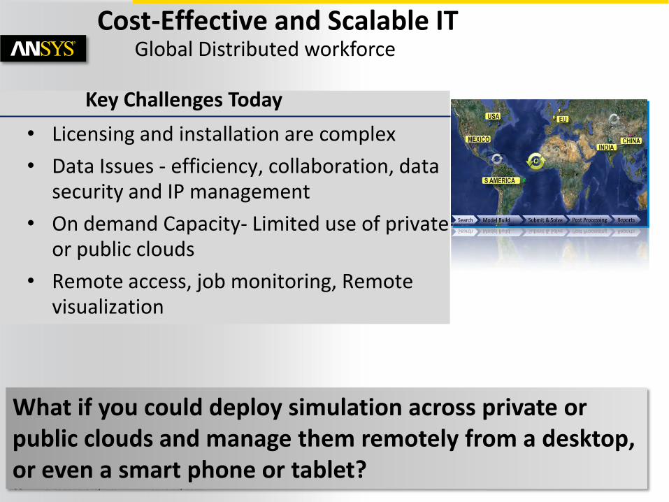
Cost-Effective and Scalable IT
What if you could deploy simulation across private or public clouds and manage them remotely from a desktop, or even a smart phone or tablet?
• Licensing and installation are complex
• Data Issues - efficiency, collaboration, data security and IP management
• On demand Capacity- Limited use of private or public clouds
• Remote access, job monitoring, Remote visualization
Key Challenges Today
Global Distributed workforce

© 2012 ANSYS, Inc. June 21, 2012 39
Click to edit Master text styles
5: Collaboration& Data/Knowledge Management
1960 2020
SIMULATION COSTS
NUMBER OF SIMULATIONS
DATA & COMPLEXITY
Component | Subsystem | System
Network Speed Computer Speed Hardware Parallel Computing
MULTIPHYSICS , ROBUST DESIGN & SYSTEMS APPROACH WILL CALL FOR BETTER IP MANAGEMENT
Traditional Growth – Linear Robust Design & Parametric Studies – Exponential
• What if we build a non intrusive system that brings CAE collaboration for systematic management of simulation data and its associated processes of creating, organizing and reusing.

© 2012 ANSYS, Inc. June 21, 2012 40
Mega
Bytes
Kilo
Bytes
Tera/Peta
Search Model Build Runs Archival Results/Reports
Test - Co-relation
Explosion of CAE Data

© 2012 ANSYS, Inc. June 21, 2012 41
EKM: Engineering Knowledge Management
Strategic Intent:
• Get the right CAE data
• to the right people
• at the right time
© 2012 ANSYS, Inc. June 21, 2012 42
Click to edit Master text styles
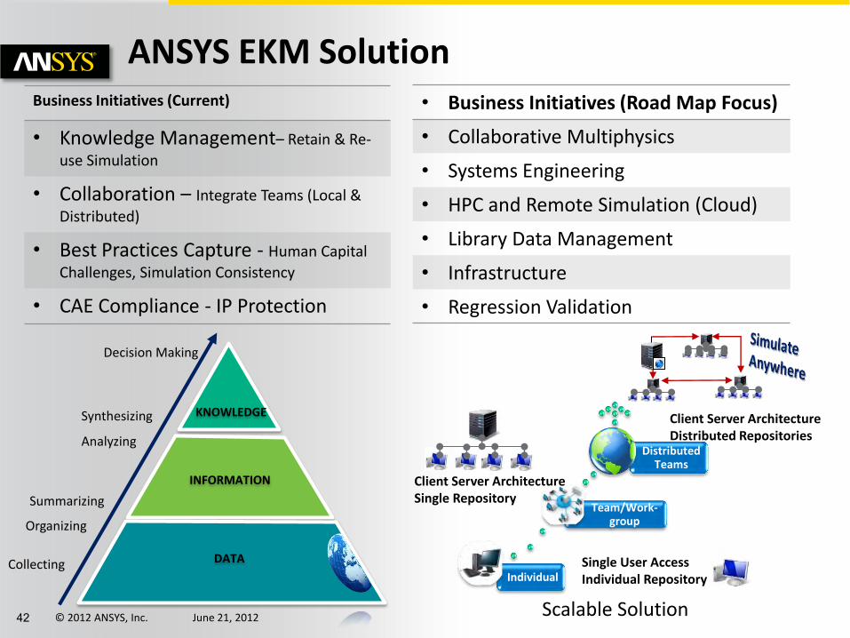
ANSYS EKM Solution Business Initiatives (Current)
• Knowledge Management– Retain & Re-
use Simulation
• Collaboration – Integrate Teams (Local &
Distributed)
• Best Practices Capture - Human Capital
Challenges, Simulation Consistency
• CAE Compliance - IP Protection
• Business Initiatives (Road Map Focus)
• Collaborative Multiphysics
• Systems Engineering
• HPC and Remote Simulation (Cloud)
• Library Data Management
• Infrastructure
• Regression Validation
KNOWLEDGE
INFORMATION
DATA Collecting
Organizing
Summarizing
Analyzing
Synthesizing
Decision Making
Individual
Team/Work-group
Distributed Teams
Single User Access Individual Repository
Client Server Architecture Single Repository
Client Server Architecture Distributed Repositories
Scalable Solution

© 2012 ANSYS, Inc. June 21, 2012 43
Value Drivers
Broadly Recognized
Evolving
Nascent – Emerging
Incremental Significant Transformational
Impact on Design Success
Challenge to Adopt
Lowest Moderate Highest
Multiphysics Simulation
Systems Simulation
Stochastic Simulation Complexity
Analysis
CAD Integration
Optimization Simulation Data Management
Analytics
Error Estimation and Control
Advanced Materials Modeling
Adapt Gaming
Technology
MEMS/Nano Simulation Multisensory
Feedback
Sou
rce:
NA
FEM
S
APPLICATION CLASSES WITH GREATEST VALUE
National Agency for Finite Element Methods and Standards

© 2012 ANSYS, Inc. June 21, 2012 44
Next
A Journey through these initiatives in the context of the Offshore Exploration and Operations
Smart Products
Robust Design
Amplify Engineering
Scalable and Cost Effective IT Solutions
Open Collaboration Platform

© 2012 ANSYS, Inc. June 21, 2012 45
System Simulation for Subsea Applications
Scott Stanton Technical Director
Ryan Magargle Lead Application Engineer

© 2012 ANSYS, Inc. June 21, 2012 46
Click to edit Master text styles
Subsea Power Distribution
Framo Engineering http://www.tekna.no/ikbViewer/Content/22993/Nils%20Arne%20S%C3%B8lvik.pdf

© 2012 ANSYS, Inc. June 21, 2012 47
Click to edit Master text styles
Voice of Customers Use Cases
List of Features Define Specifications
Functional Representation and Models
Component Selection and Sub-System Simulation

© 2012 ANSYS, Inc. June 21, 2012 48
Click to edit Master text styles CAD Physics Based Solvers Embedded*
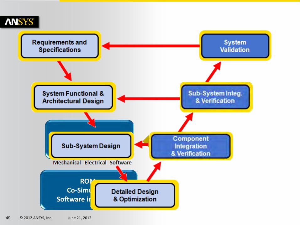
© 2012 ANSYS, Inc. June 21, 2012 49
Click to edit Master text styles
Virtual Prototyping
Subassembly integration
ROM Co-Simulation
Software integration

© 2012 ANSYS, Inc. June 21, 2012 50
Click to edit Master text styles
• Components: Rating and Sizing
– Power, Efficiency and Reliability
• Size and weight of power converters must be appropriate for intended application:
– E.g. Mobile ROV applications vs. fixed seafloor equipment
– System level decision: Choosing operating frequencies and voltages levels for distribution
Subsea Power Distribution: Engineering Challenges
http://www.schilling.com/products/ROVs/Pages/default.aspx http://images.pennnet.com/articles/os/cap/cap_0606offcep2.jpg http://abb.com

© 2012 ANSYS, Inc. June 21, 2012 51
Click to edit Master text styles
• Systems need to operate dependably within their rated lifetimes
– System level decision: Materials, dimensions, and electronic controls designed to minimize excess wear from steady state, transient, and fault conditions.
– Cable losses and overvoltage
– Transient startup inrush
– Short and open circuit events
Subsea Power Distribution: Engineering Challenges
http://www.schilling.com/products/ROVs/Pages/default.aspx http://images.pennnet.com/articles/os/cap/cap_0606offcep2.jpg http://abb.com

© 2012 ANSYS, Inc. June 21, 2012 52
Click to edit Master text styles
soft-starter
36kV600V 6000V
soft-starter0
0
0
0
0
0
0
0 0 0
0
0
000
0 0
+
V
VM1
EQU
FML3
id:=2/3*(cos(phiel)*WM1.I + cos(phiel - 2*pi/3)*WM2.I + cos(phiel - 4*pi/3)*WM3.I)iq:=2/3*(sin(phiel)*WM1.I + sin(phiel - 2*pi/3)*WM2.I + sin(phiel - 4*pi/3)*WM3.I)
W
+
WM1
W
+
WM2
W
+
WM3
ICA:
FML_INIT1
VSI_3ph_avg
VSI3ph_A1
A
B
C
N
ROT1
ROT2
+
F
SM_ROT1
w
+
VM_ROT1
MASS_ROT1
T
FM_ROT1
SIMPARAM1
T
F_ROT1
~
3PHAS
~
~
A * sin (2 * pi * f * t + PHI + phi_u)
PHI = 0°
PHI = -120°
PHI = -240°
THREE_PHASE1
B6U
D1 D3 D5
D2 D4 D6
B6U1R1
+
V
+
V
+
V
+
V
+
V
+
V
TWT
TWT1
TWT
TWT2
TWT
TWT3
U3Simplorer1
Generator Step-Up
Transformer
Cable Step-Down
Transformer
Rectifier Inverter Booster
Pump
Controller
Represent subsea network components with models
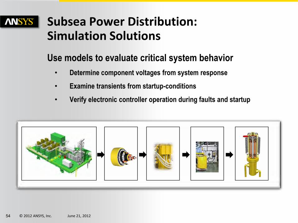
Subsea Power Distribution: Simulation Solutions
Topside Power Cable Umbilical Booster Pump Power Converter

© 2012 ANSYS, Inc. June 21, 2012 53
Click to edit Master text styles
Subsea Power Distribution: Simulation Solutions
FEA/Numerical Models
• Cable
• Electric Machine (Booster Pump)
Analytical Models
• Transformers
Behavioral Models
• Inverter
• Electronic Drive Controller
© 2012 ANSYS, Inc. June 21, 2012 54
Click to edit Master text styles
Use models to evaluate critical system behavior
• Determine component voltages from system response
• Examine transients from startup-conditions
• Verify electronic controller operation during faults and startup
Subsea Power Distribution: Simulation Solutions

© 2012 ANSYS, Inc. June 21, 2012 55
Click to edit Master text styles
Topside Power: Analytical Representation
© 2012 ANSYS, Inc. June 21, 2012 56
Click to edit Master text styles
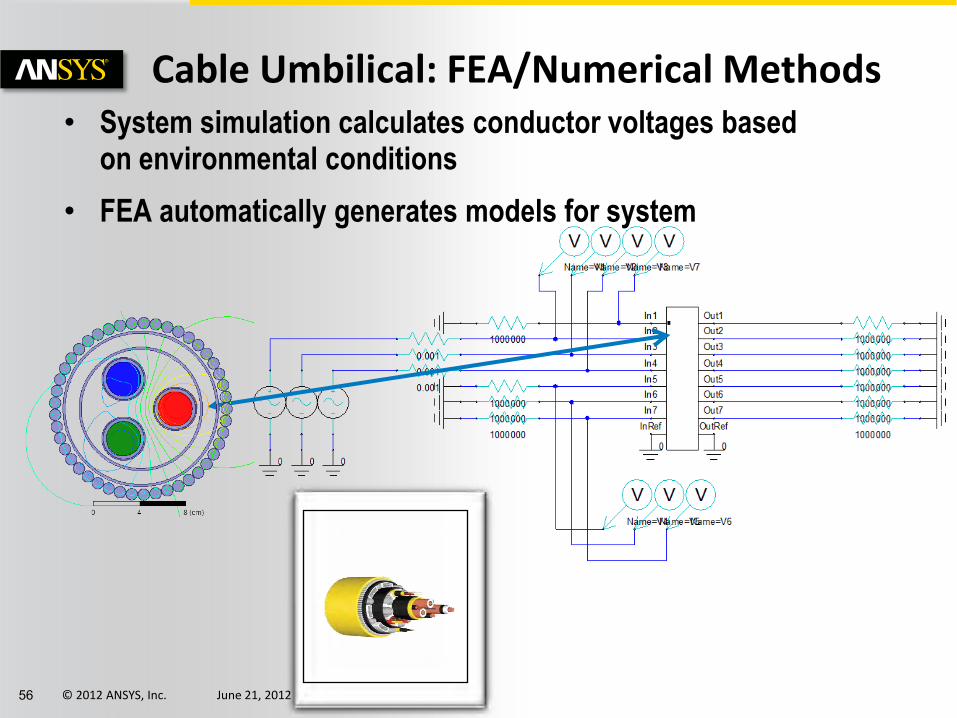
Cable Umbilical: FEA/Numerical Methods • System simulation calculates conductor voltages based
on environmental conditions
• FEA automatically generates models for system

© 2012 ANSYS, Inc. June 21, 2012 57
Click to edit Master text styles
Cable Umbilical: FEA/Numerical Methods Verify Material Breakdown for Reliability
• Map worst case voltage to FEM field simulation
• Observe electric field intensity for breakdown
0.00 10.00 20.00 30.00 40.00Time [ms]
-6.00
-4.00
-2.00
0.00
2.00
4.00
6.00
Vo
lta
ge
[k
V]
Core Phase Voltages ANSOFT
Curve InfoPhaseA
NexximTransientPhaseB
NexximTransientPhaseC
NexximTransient

© 2012 ANSYS, Inc. June 21, 2012 58
Click to edit Master text styles
Power Converter: Analytical Representation
© 2012 ANSYS, Inc. June 21, 2012 59
Click to edit Master text styles
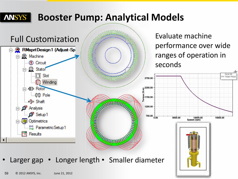
Booster Pump: Analytical Models
Full Customization
• Larger gap
Evaluate machine performance over wide ranges of operation in seconds
• Longer length
• Smaller diameter

© 2012 ANSYS, Inc. June 21, 2012 60
Click to edit Master text styles
Booster Pump: FEA/Numerical Models
Electrical Mechanical
Model for System 3D FEM Model
Automatically Generate System and 3D FEM Models for Simulation

© 2012 ANSYS, Inc. June 21, 2012 61
Click to edit Master text styles
Electric Drive Controller
Analog
Digital
Implement control algorithms in a natural way prior to hardware implementation

© 2012 ANSYS, Inc. June 21, 2012 62
Click to edit Master text styles
Bringing it all Together
0.00 2.50 5.00 7.50 10.00 12.50Time [s]
0.00
1500.00
3000.00
4500.00
6000.00
7000.00
Pu
mp
Sp
ee
d [
rpm
]
Pump Startup Speed ANSOFT
soft-starter
36kV600V 6000V
soft-starter0
0
0
0
0
0
0
0 0 0
0
0
000
0 0
+
V
VM1
EQU
FML3
id:=2/3*(cos(phiel)*WM1.I + cos(phiel - 2*pi/3)*WM2.I + cos(phiel - 4*pi/3)*WM3.I)iq:=2/3*(sin(phiel)*WM1.I + sin(phiel - 2*pi/3)*WM2.I + sin(phiel - 4*pi/3)*WM3.I)
W
+
WM1
W
+
WM2
W
+
WM3
ICA:
FML_INIT1
VSI_3ph_avg
VSI3ph_A1
A
B
C
N
ROT1
ROT2
+
F
SM_ROT1
w
+
VM_ROT1
MASS_ROT1
T
FM_ROT1
SIMPARAM1
T
F_ROT1
~
3PHAS
~
~
A * sin (2 * pi * f * t + PHI + phi_u)
PHI = 0°
PHI = -120°
PHI = -240°
THREE_PHASE1
B6U
D1 D3 D5
D2 D4 D6
B6U1R1
+
V
+
V
+
V
+
V
+
V
+
V
TWT
TWT1
TWT
TWT2
TWT
TWT3
U3Simplorer1
Generator Step-Up
Transformer
Cable Step-Down
Transformer
Rectifier Inverter Booster
Pump
Controller
Validate Components Behavior with Rapid Full System Simulation
© 2012 ANSYS, Inc. June 21, 2012 63
Click to edit Master text styles
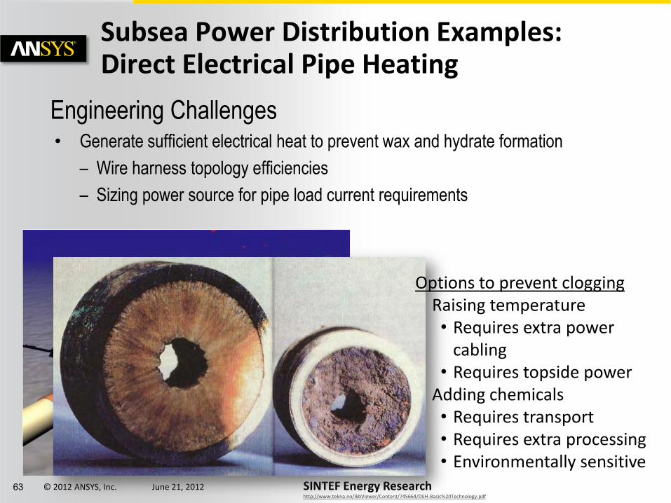
Subsea Power Distribution Examples: Direct Electrical Pipe Heating
Engineering Challenges • Generate sufficient electrical heat to prevent wax and hydrate formation
– Wire harness topology efficiencies
– Sizing power source for pipe load current requirements
SINTEF Energy Research http://www.tekna.no/ikbViewer/Content/745664/DEH-Basic%20Technology.pdf
Options to prevent clogging Raising temperature • Requires extra power
cabling • Requires topside power
Adding chemicals • Requires transport • Requires extra processing • Environmentally sensitive
© 2012 ANSYS, Inc. June 21, 2012 64
Click to edit Master text styles
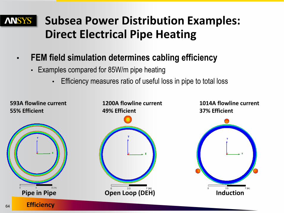
• FEM field simulation determines cabling efficiency
• Examples compared for 85W/m pipe heating
• Efficiency measures ratio of useful loss in pipe to total loss
Subsea Power Distribution Examples: Direct Electrical Pipe Heating
Pipe in Pipe Open Loop (DEH)
Efficiency
Induction
1200A flowline current 49% Efficient
1014A flowline current 37% Efficient
593A flowline current 55% Efficient
© 2012 ANSYS, Inc. June 21, 2012 65
Click to edit Master text styles
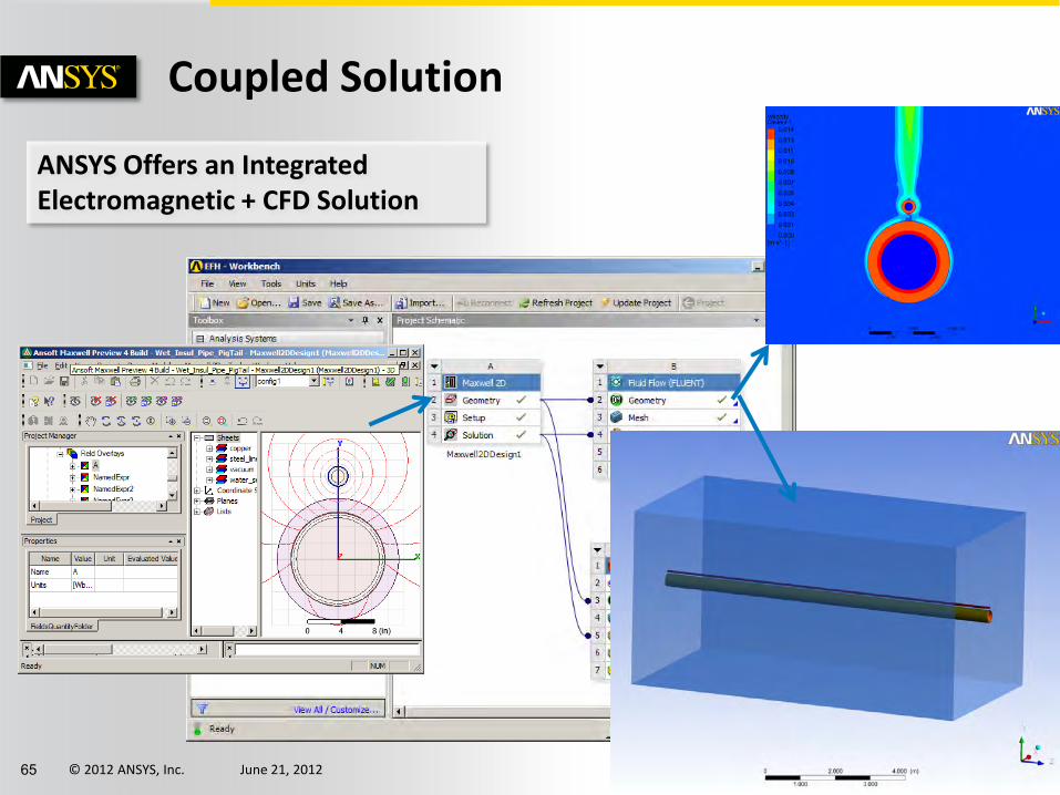
Coupled Solution
ANSYS Offers an Integrated Electromagnetic + CFD Solution

© 2012 ANSYS, Inc. June 21, 2012 66
0
0
R3
R4
R5
~
3PHAS
~
~
A * sin (2 * pi * f * t + PHI + phi_u)
PHI = 0°
PHI = -120°
PHI = -240°
THREE_PHASE1
TWT
TWT
TWT
C2
L3
C3
cable_copper_Acable_copper_B
Subsea Power Distribution Examples: Direct Electrical Pipe Heating
0.00 100.00 200.00 300.00 400.00Time [ms]
-0.20
0.00
0.20
0.40
0.60
0.80
1.00P
WR
_P
rob
e1
.PF
E
Power Factor ANSOFT
Optimize compensation capacitor
Automatically search and size capacitor for 0.9 PF
FEM simulation of cable
DEH Cable

© 2012 ANSYS, Inc. June 21, 2012 67
0
0
R3
R4
R5
~
3PHAS
~
~
A * sin (2 * pi * f * t + PHI + phi_u)
PHI = 0°
PHI = -120°
PHI = -240°
THREE_PHASE1
TWT
TWT
TWT
C2
L3
C3
cable_copper_Acable_copper_B
Subsea Power Distribution Examples: Powerline cabling
• Complex cable geometry electrical parasitics are extracted and dynamically linked to the System Simulator
• Increased cable lengths see greater signal delay and oscillation.
© 2012 ANSYS, Inc. June 21, 2012 68
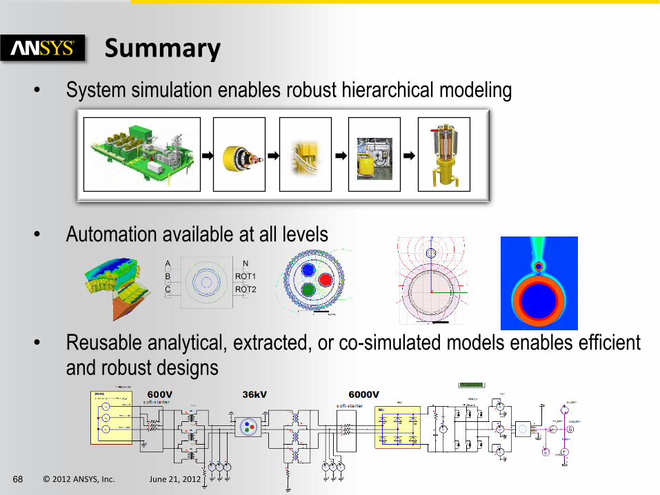
• System simulation enables robust hierarchical modeling
• Automation available at all levels
• Reusable analytical, extracted, or co-simulated models enables efficient and robust designs
Summary


