Congestion Driven Placement for VLSI Standard Cell Design Shawki Areibi and Zhen Yang School of Engineering, University of Guelph, Ontario, Canada December 2003 ([email protected], [email protected]) ICM 2003, Cairo
Transcript
Congestion Driven Placement for VLSI Standard
Cell Design
Shawki Areibi and Zhen Yang
School of Engineering, University of Guelph, Ontario, Canada
• The interconnect has become a critical determiner of circuit performance in the deep sub-micron regime.
• Circuit placement is starting to play an important role in today’s high performance chip designs.
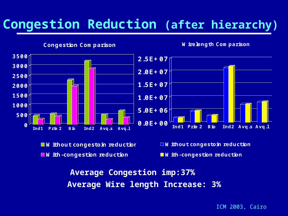
• In addition to wire length optimization, the issue of reducing excessive congestion in local regions such that the router can finish the routing successfully is becoming another important problem.
ICM 2003, Cairo
VLSI Design
Physical Design
Partitioning
Routing
Placement
4
Specification
Architectural design
Circuit design
Physical design
Test/Fabrication
Logic design
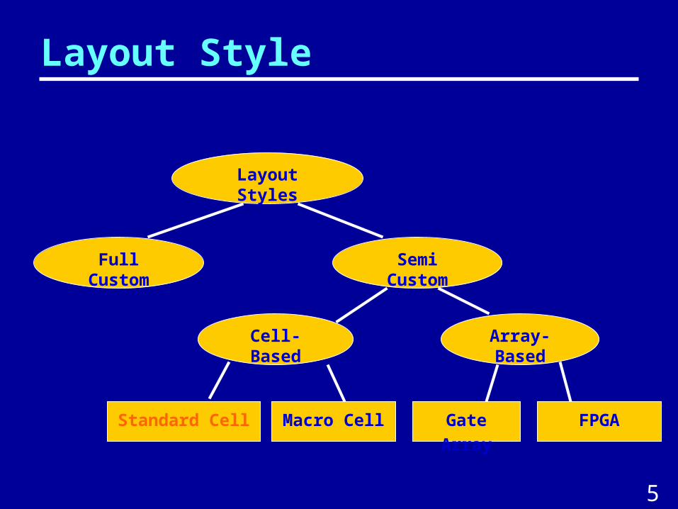
Layout Styles
Semi Custom
Full Custom
Standard Cell
Cell-Based Array-Based
Macro Cell Gate Array FPGA
Layout Style
5
Standard Cell Layout Style
Feature: Row based layout
Standard cells
Routing channel
Advantages: High productivity More efficient space Well-suited for automated design
Standard cell
Routing Channel
I/O PadsFeedthrough
6
Circuit Layout - Partitioning
8
Partition circuit into several sub-circuits.
Minimize the number of connections between the components.
Make the size of each
Objectives
component within prescribed ranges
Task
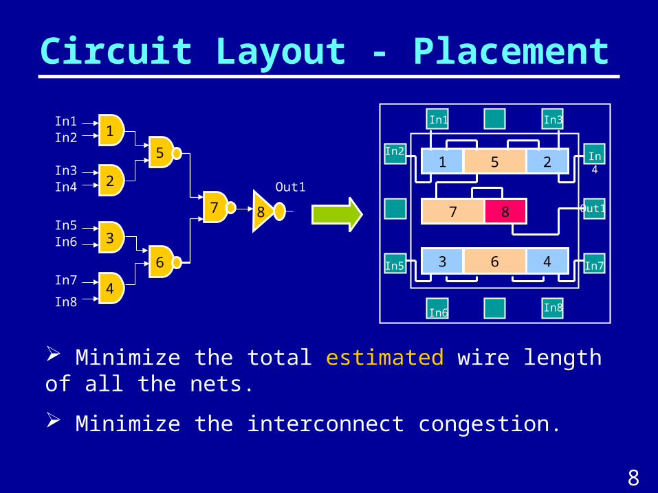
Circuit Layout - Placement
2
1
4
3
8
6
5
7
In8
In7
In6In5
In4In3
In2In1
Out1
8
1 5 2
3 6 4
7
In8
In5
In2
In1 In3
In4
In6
In7
Out1
Minimize the total estimated wire length of all the nets.
Minimize the interconnect congestion.
8
Circuit Layout – Global Routing
Minimize the total wire length and critical path delay.
10
Objectives
Circuit Layout
Typical Objectives
Minimize the chip area
Minimize the interconnect
delay
L
D W
H
OR
L
E
T
O
LH OLE
W LO R D
Determine the location of modules. Connect the modules inside the boundary of a VLSI chip.
10
Why Is Placement Important?
The first phase in the VLSI design that determines the physical layout of a chip.
- The quality of the attainable routing is highly determined by the placement.
11
- Circuit Placement becomes very critical in today’s high performance VLSI design.
The circuit delay, power dissipation and area are dominated by the interconnections.
1.0um 0.5um 0.25um
1.0
0.1
Minimum Feature Size
Dela
y
(ns0
Gate delay
Interconnect delay
Placement Techniques
Placement Algorithms
Constructive Placement
Iterative Improvemen
t
Partitioning Placement
NumericalOptimizatio
n
ClusterGrowth
Technique
SimulatedAnnealin
g
Force-directed
Placement
Genetic Placement
12
Traditional Placement Approach
Initial (global) Placement
by Constructive Algorithms
Initial (global) Placement
by Constructive Algorithms
Improve (detailed) Placement
by Iterative Algorithms
Improve (detailed) Placement
by Iterative Algorithms
Valid Coordinates for each cell
Produce a good initial placement in reasonable time