Connected Imaging-Performance and Management Design and Implementation Guide
This document is intended to provide information on the implementation and configuration of the Performance and Management solution, part of the Cisco Connected Imaging portfolio that delivers fast, effective image services across the healthcare workflow.
It is assumed that administrators of this solution will have experience with installation and acceptance of the products covered by this network design. In addition, it is assumed that the administrator understands the procedures required to upgrade and troubleshoot networks at a basic level.
Typical users of this guide include the follow groups:
• Customers with technical staff experienced enough to perform the installation and configuration of the elements required for this solution
• Cisco sales engineers and advanced services personnel assisting customers with the implementation of the elements required for this solution
• Service integrators and Cisco partners assisting customers with the implementation of the elements required for this solution
• System administrators who are responsible for installing and configuring internetworking equipment, and who are familiar with Cisco IOS
ContentsSolution Overview 3
Executive Summary 3Solution Description 3Target Market 4Solution Benefits 4Solution Features 4Scope of the Solution 5Process Flow 7
Cisco Systems, Inc., 170 West Tasman Drive, San Jose, CA 95134-1706 USA
Contents
Solution Architecture 8Performance and Management Architecture 8Normal Image Flow 10
Failover of a Switch and/or CSS 13
Solution Features and Components 15
Hardware and Components 15
Software 16
Features and Functionality 16
Features, Services, and Application Design Considerations 17
Scalability and Capacity Planning 17
High Availability 18
Security 18
Implementing and Configuring the Solution 18
Implementation or Testing Approach 18
Implementation Overview 18
What was Implemented/Tested 18
What was Not Implemented/Tested 19
Test Network Topology 19
Lab Components 21
Hardware Tested 21
Software Tested 22
Testing Tools 22
Configuration Task Lists 22
Configuration and Menus 25
Troubleshooting Configuration 26
Results and Conclusions 29
Caveats and Limitations 29
Appendix A—Equipment Configurations 30
4948A and 4948B (L2/L3 switches) 30
CSS1 and CSS2 (L4 Load-Balancer) 34
4948C and 4948D (Access Switch) 37
Appendix B—DICOM Header Information 41
2Connected Imaging-Performance and Management Design and Implementation Guide
OL-14454-01
Solution Overview
Solution Overview
Executive SummaryThe Connected Imaging-Performance and Management solution is based on Cisco and partner technologies to provide a highly available and scalable infrastructure to support the various Picture Archive Communication Systems (PACS) in use today. The Connected Imaging-Performance and Management solution addresses scalability, application, and storage performance challenges with advanced networking, image routing, and storage technologies. This end-to-end image management solution improves image availability, and provides superior storage performance at a lower cost by optimizing existing infrastructure and reducing additional, unnecessary investments. Through the Cisco Medical-Grade Network, the Connected Imaging-Performance and Management solution provides scalable imaging services and increases PACS performance, to manage modern high-bandwidth images. This solution supports centralized image storage for quick image access and retrieval across a distributed storage environment.
The applications of these products are produced through direct consultation with radiology or imaging services providers to address many key concerns as the growth and complexity of imaging services increases exponentially. By addressing these issues, the Connected Imaging-Performance and Management solution can provide direct value to clinical leadership and enable the clinical leadership to include advanced infrastructure technologies in imaging services budgets.
Solution DescriptionPACS is at the core of medical image management. PACS consists of a cluster of application, database, and web servers. Although the PACS architecture dictates the quantity and function of the servers, they all require high availability; typically greater than 99.99 percent. When more than a single PACS server and/or multiple modalities are present, it is often difficult to provide high availability and fault tolerance.
Coupling Cisco core technologies with DICOM Services GridTM software from Acuo Technologies® effectively enhances image management performance. The AcuoMed Image Manager is a secure, open-system software solution for transporting, storing, tracking, and retrieving digital images across an entire storage system network. AcuoMedTM Image Manager is a DICOM 3.0 Level 2-compliant solution that uses Microsoft Windows 2000, 2003 Server, or Microsoft Windows XP Professional on a recommended AMD platform. AcuoMed works in conjunction with AcuoStore, a digital asset manager. AcuoStore serves as a digital vault, communicating the instructions of AcuoMed with the diverse DICOM storage devices in which digital DICOM image and patient information is contained.
Each Acuo system works in concert with other DICOM devices to create local intelligent workflow using its dynamic router, enabling a single view of the entire DICOM network through its peer-aware collaboration feature. The next generation of Acuo technology offers local caching of image data, seamless integration of legacy data, and interoperability with the available information systems for real-time image reconciliation and RIS/PACS synchronization.
Located in front of these DICOM routers (also known as DICOM Services Grid), the Cisco Content Services Switch (CSS) dynamically load balances the traffic between the DICOM routers in the grid. This is accomplished through the use of the Acuo Load Optimizer, which monitors the work queues on each DICOM router and sends updates to the CSS when a particular router is loaded beyond a pre-defined threshold. When this happens, the CSS lowers the weight of that particular router and sends the data to one of the others in the configuration.
3Connected Imaging-Performance and Management Design and Implementation Guide
OL-14454-01
Solution Overview
This dynamic load balancing integration between the CSS and the Acuo DICOM routers makes this a unique solution in the healthcare market.
For more information on the Acuo solutions and software, see the Acuo website at the following URL: http://www.acuotech.com.
Target MarketThis phase of the solution targets small-to-midsize hospitals and radiology clinics. These are typically smaller institutions with single or minimal radiology departments and multiple modalities that would benefit from the high availability and extensibility of the solution.
The interested party at a customer site for this solution is most likely the CIO or CTO, as well as the IT management. Because it is primarily targeted at enhancing the backend storage, network, and imaging workflow solutions, as well as the availability and management of those products, they are most likely to understand the benefits of the solution.
It is not likely that radiologists or radiology departments will be the primary target, because the particulars of this solution deal with the availability of the storage device, as well as imaging workflow and network issues. However, because there are other functions that the Acuo DICOM Services Grid can provide (for example, image cache), and the solution does enhance the performance of the availability of the image in the overall workflow, they should not be ignored.
Solution Benefits The Connected Imaging-Performance and Management solution improves the performance and scalability of the multi-vendor PACS systems used by healthcare providers. Modern imaging requires large amounts of resources because of the size of the images, sometimes in the gigabit range. To complicate the issue, each vendor has their own proprietary protocol.
The CSS improves the overall scalability by intelligently load balancing the PACS/DICOM traffic to the Acuo DICOM Services Grid.
The Acuo DICOM Services Grid is an enabling open-systems software solution that facilitates a DICOM infrastructure built on a services-oriented architecture that can aggregate/federate DICOM objects and query results, virtualize and replicate storage assets, and is built on a collaborative and extensible grid computing model.
The Connected Imaging-Performance and Management solution provides the ability to connect proprietary PACS systems such that they operate together seamlessly. It also allows images to be routed based on metadata contained in the DICOM header. The Acuo DICOM Services Grid directs the image traffic based on a set of business rules, and provides image storage services by either placing into storage or forwarding to the diagnostic workstation.
Solution Features The Connected Imaging-Performance and Management solution addresses multiple challenges in healthcare today. It enables healthcare organizations to reduce patient scan times, effects a high availability application environment, and improves patient satisfactions.
The solution solves these challenges by configuring the components in the solution to allow for the following:
• Highly available single point of access for modalities
4Connected Imaging-Performance and Management Design and Implementation Guide
• Real-time adaptive load optimization through integration with the Acuo DICOM Services Grid
Scope of the SolutionThis solution is limited to the time in the workflow from image acquisition at the modality to storage, PACS, third-party DICOM workstations (for example, 3D), and long-term storage managed by the DICOM Services Grid.
This design guide is intended to provide information on the implementation and configuration of the components required to provide intelligent load balancing of DICOM images using CSS switches and Acuo DICOM routers. Although guidelines are offered related to extensibility, no specific scalability recommendations are provided. Also not included is capacity planning. Because the solution is easily extensible, care should be taken in the design to allow for baseline projections and then a gradual implementation to allow for adequate bandwidth and processing to support the imaging environment. More information can be obtained from Acuo Technologies related to sizing Acuo DICOM Services Grid implementations at the following URL: http://www.acuotech.com.
The radiology workflow is a multi-step process with large file transfers and multiple communications and is focused on the steps shown in Figure 1.
Figure 1 Radiology Workflow
The workflow can be made more efficient through the implementation of a DICOM services layer to more effectively route DICOM traffic. (See Figure 2.) This allows for intelligent routing of the images based on information in the DICOM header and business rules that are configured in the Acuo DICOM Services Grid software. Additional capabilities of the DICOM services layer, although not included in this phase of the solution, include caching, better performance on image retrievals, and allowing for expanded collaboration within the imaging environment.
TechnologistPerforms
Exam
Technologistassigned exam
Modalitylocated for
exam
Patient locatedand transported
to exam
Physicianordersimage
Examscheduled andcreated in RIS
Radiologistdictatesresults
Radiologistinterpretsimages
Imagesavailable forinterpretation
Patient Departs
Physiciantreatspatient
Resultsavailable tophysician
Resultstranscribed
Transportretrieves patient/waits for results
Stat Imageavailable for
specialist review
Radiologistprovides preliminary
consult
Techcompletes
exam, updates order status
Patient Arrives
2219
20
5Connected Imaging-Performance and Management Design and Implementation Guide
6Connected Imaging-Performance and Management Design and Implementation Guide
OL-14454-01
Solution Overview
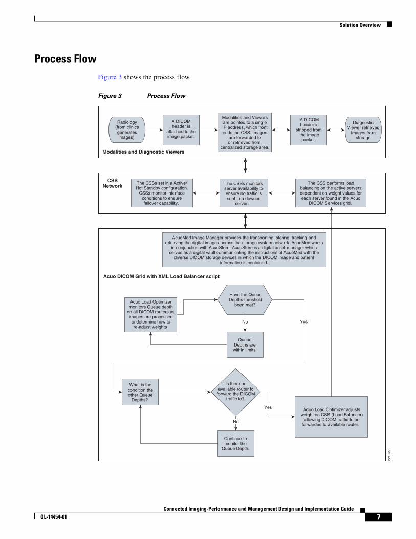
Process FlowFigure 3 shows the process flow.
Figure 3 Process Flow
Radiology(from clinicsgeneratesimages)
A DICOMheader is
attached to theimage packet.
Have the QueueDepths threshold
been met?
QueueDepths arewithin limits.
What is thecondition theother Queue
Depths?
Acuo Load Optimizermonitors Queue depth
on all DICOM routers asimages are processedto determine how tore-adjust weights
Continue tomonitor the
Queue Depth.
Is there anavailable router to
forward the DICOMtraffic to?
Acuo Load Optimizer adjustsweight on CSS (Load Balancer)
allowing DICOM traffic to beforwarded to available router.
Yes
Modalities and Viewersare pointed to a singleIP address, which frontends the CSS. Images
are forwarded toor retrieved from
centralized storage area.
DiagnosticViewer retrieves
Images fromstorage
A DICOMheader is
stripped from the imagepacket.
The CSS performs loadbalancing on the active serversdependant on weight values foreach server found in the Acuo
DICOM Services grid.
The CSSs set in a Active/Hot Standby configuration.
CSSs monitor interfaceconditions to ensurefailover capability.
The CSSs monitorsserver availability toensure no traffic issent to a downed
server.
AcuoMed Image Manager provides the transporting, storing, tracking andretrieving the digital images across the storage system network. AcuoMed works
in conjunction with AcuoStore. AcuoStore is a digital asset manager whichserves as a digital vault communicating the instructions of AcuoMed with the
diverse DICOM storage devices in which the DICOM image and patientinformation is contained.
Acuo DICOM Grid with XML Load Balancer script
CSSNetwork
Modalities and Diagnostic Viewers
No
No
Yes
2219
22
7Connected Imaging-Performance and Management Design and Implementation Guide
OL-14454-01
Solution Architecture
Solution Architecture
Performance and Management ArchitectureThe Cisco Service-Oriented Network Architecture (SONA) provides a foundation for performance and management. (See Figure 4.) This architecture identifies an end-to-end system offering to provide adaptive image routing to medical facilities that require better care for their patients. Connected Imaging-Performance and Management is an integrated solution of Cisco and partner products to provide a highly available foundation for image routing in the healthcare environment.
Figure 4 Performance and Management Architecture
The following three layers provide the architectural foundations of the Connected Imaging-Performance and Management solution that deliver an innovative solution offering to solve the challenges image routing in healthcare today:
• Network infrastructure layer—Covers the various network locations from which images may originate, are read, or are stored. These locations include specific locations inside a hospital where the design follows a campus or branch office design.
• Interactive services layer—Brings in the Acuo DICOM Services Grid to add the agent for the DICOM Services layer previously discussed.
• Application Layer—Combines the PACS systems, diagnostic stations, and modalities through the adaptive image routing provided by the Acuo DICOM Services Grid software.
2219
23
MeetingPlace
Healthcare Applications Cisco Collaborative Care
Security Services
Mobility Services
Storage Services
Compute Sevices
Identity Services
Unified CommunicationsServices
IntegratedNetwork Services
Network Infrastructure Virtualization
Data Center
Network Systems
Branch
HospitalCampus
RadiologyDepartments
EmergencyRoom
OperatingRoom
DiagnosticCenters
ImagingClinics
LIS/RISCIS
CallManagerPACSHealthcare
Applications
Man
ag
em
en
t S
erv
ices
Application Delivery Acuo DICOM Services Grid
WAN/MAN
8Connected Imaging-Performance and Management Design and Implementation Guide
OL-14454-01
Solution Architecture
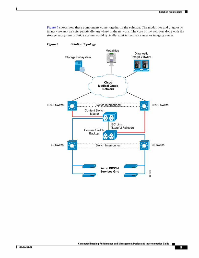
Figure 5 shows how these components come together in the solution. The modalities and diagnostic image viewers can exist practically anywhere in the network. The core of the solution along with the storage subsystem or PACS system would typically exist in the data center or imaging center.
Figure 5 Solution Topology
Storage Subsystem
ModalitiesDiagnostic
Image Viewers
L2/L3 Switch
Content SwitchMaster
Content SwitchBackup
Acuo DICOMServices Grid
CiscoMedical Grade
Network
ISC Link(Stateful Failover)
L2 Switch
L2/L3 Switch
L2 Switch Switch Interconnect
Switch Interconnect
2219
24
9Connected Imaging-Performance and Management Design and Implementation Guide
OL-14454-01
Solution Architecture
Normal Image FlowAs images are acquired by the modalities, the PACS image data is forwarded to the storage array for viewing at later time, as shown in Figure 6.
Figure 6 Normal Image Flow
The sequence is as follows:
1. The image data is formatted with a DICOM header (this is accomplished with Testman, a DICOM Generator used for testing purposes) that flows through the Cisco Medical-Grade Network (Cisco MGN) to the 4948A.
Cisco 4948 B
Cisco MGN
CSS Master
CSS Backup
Acuo DICOMServices Grid
DICOMGenerator
NAS StorageSubsystem
ISC Link(Stateful Failover)
Cisco 4948 C
Cisco 4948 A
Cisco Catalyst 3750
Cisco 4948 C 2 gb Etherchannel Trunk
SQL Server10.0.40.100/24
10.0.40.101/24
10.0.40.110/24
10.0.40.104/24
10.0.40.102/24
Redundant VIP10.0.20.5/24
Packets aresent via IP/TCPon Posrt 4321
HSRP IP 10.0.20.11/24
Redundant IF10.0.40.1/24
10.0.40.105/24
2 gb Etherchannel Trunk
2219
25
1
2
6
4
3
5
VLAN 20VLAN 40
10Connected Imaging-Performance and Management Design and Implementation Guide
OL-14454-01
Solution Architecture
2. The 4948A is matched with another 4948B to provide redundancy in case of unit failure via Hot Standby Routing Protocol (HSRP). The 4948A and 4948B provide Layer 3 and Layer 2 capabilities, where the Layer 3 side provides routing into the MGN and the Layer 2 side provides connectivity to the front-end of the CSS.
3. The modalities and diagnostic viewers connect to the CSSs via a single IP address (virtual) provided by the CSSs. Using the virtual IP address on the CSSs allows the modalities and diagnostic viewers to remain connected when the active CSS fails over to the hot standby CSS. The CSSs use an Inter-Switch Communications (ISC) link to allow the CSS peers to exchange flow state information in an Adaptive Session Redundancy (ASR) configuration. If the master CSS fails, the backup CSS already has the flow state information necessary to continue the current flows without interruption. Using ISC, CSSs exchange state information as follows:
– For existing flows, at boot-up time and at VIP redundancy failover
– For new flows, in real time (after the CSS receives a SYN/ACK from the server)
The CSSs monitor their respective interfaces to ensure redundancy as an interface/link fails.
4. A service is created on the CSS for each server found on the DICOM Services Grid. These services contain the following information regarding the servers:
– Server name
– Server IP address
– Server weight
– Server port
– Server keepalive
The service monitors the connectivity to the servers via an ICMP keepalive to ensure that traffic is not sent to a downed or inactive server. The CSS uses Weighted Round Robin (WRR) to forward the image traffic to the Acuo DICOM Services Grid. The Acuo Load Optimizer service running on the primary server in the Acuo DICOM Services Grid monitors the queue depth of each of the servers in the grid and updates the service on each of the CSSs based on the load on each server. As the queue depth of a server becomes longer, the Acuo Load Optimizer service connects to the CSS and changes the weight to a lower value for that server. This causes the incoming image traffic to connect and flow to other servers that have higher weight values in the CSS and shorter queues on the DICOM router.
Note Keepalives from CSS to Acuo servers may be ICMP type or TCP type with port number. ICMP type is recommended for keepalives. If TCP type is used, make sure the assigned port number does not conflict with Acuo active port numbers (i.e., use port 10000). Check with Acuo for specific port numbers to use.
5. The Acuo DICOM Services Grid consists of Windows 2003 Server with an internal SQL database or an external SQL database. The Acuo DICOM Services Grid is used to enhance image management performance. The AcuoMed Image Manager is a DICOM 3.0 Level 2-compliant solution that uses secure, open-system software for the transporting, storing, tracking, and retrieving of digital images across an entire storage system network. Each Acuo system works in concert with other DICOM devices to create local intelligent workflow using its dynamic router, enabling a single view of the entire DICOM network through its peer-aware collaboration feature. AcuoMed works in conjunction with AcuoStore, a digital asset manager. AcuoStore serves as a digital vault, communicating the instructions of AcuoMed with the diverse DICOM storage devices in which digital DICOM image and patient information is contained.
11Connected Imaging-Performance and Management Design and Implementation Guide
OL-14454-01
Solution Architecture
6. As the image traffic flows in or out of the Acuo DICOM Services Grid, AcuoMed ensures the transport of the image traffic from the storage device to the viewer, and from the modality to the storage device. AcuoStore ensures that the communications between AcuoMed and the storage device is properly maintained.
Redundancy in the Acuo Services Grid is dependant on the number of Acuo servers deployed in the solution. A minimum of two servers are required. The SQL server can be placed on the Acuo servers or on an independent server, which is the recommended topology.
The storage device can be a network-attached storage (NAS) device, or an independent storage device can be located in the following places:
• Off network. However, the data (image) traffic must be secured because of the sensitivity of the information. The Acuo servers and SQL databases must be able to communicate with the storage devices. Because of the image data re-traversing the CSS routes, this is not a recommended method because it can be a cause of congestion.
• On the same server that is running the AcuoMed and AcuoStore application. This configuration is not recommended because of the size of the images and the relative amount of internal hard drive space required.
• On the same network as the Acuo DICOM Services Grid (as shown in Figure 6). This is the recommended design because it alleviates congestion of image data traversing the CSS routes. This should be performed in the evening hours if offsite storage is required for the backup of data from the local storage device.
12Connected Imaging-Performance and Management Design and Implementation Guide
OL-14454-01
Solution Architecture
Failover of a Switch and/or CSSFigure 7 shows the sequence of events for a failover of a switch and/or a CSS.
Figure 7 Failover Sequence
The sequence is as follows:
1. The image data is formatted with a DICOM header (this accomplished with Testman, a DICOM Generator used for testing purposes) that flows through the MGN to the 4948B.
2. The 4948B is matched with another 4948A to provide redundancy in case of unit failure via HSRP. The follow failure scenarios determine the flow of traffic:
Cisco 4948 B
Cisco MGN
CSS Master
CSS Backup
Acuo DICOMServices Grid
DICOMGenerator
NAS StorageSubsystem
ISC Link(Stateful Failover)
Cisco 4948 C
Cisco 4948 A
Cisco Catalyst 3750
Cisco 4948 C 2 gb Etherchannel Trunk
SQL Server10.0.40.100/24
10.0.40.101/24
10.0.40.110/24
10.0.40.104/24
10.0.40.102/24
Redundant VIP10.0.20.5/24
Packets aresent via IP/TCPon Posrt 4321
HSRP IP 10.0.20.11/24
Redundant IF10.0.40.1/24
10.0.40.105/24
2 gb Etherchannel Trunk
2219
26
1
2
5 5
4
3
3
4
1
6 6
VLAN 20VLAN 40
13Connected Imaging-Performance and Management Design and Implementation Guide
OL-14454-01
Solution Architecture
a. 4948B MGN port connection failure—Because the link to the active CSS is operational, traffic is sent from the MGN to the redundant 4948A. The traffic then traverses across the EtherChannel to the 4948B (with the bad port) and flows to the active CSS.
b. 4948A CSS port failure or complete unit failure—Because the link to the active CSS master has failed, either by unit failure or port failure, the active CSS master goes into standby mode, forcing the CSS backup to become active. The traffic now flows from the MGN to the redundant 4948B and then to the CSS backup. Because this is a stateful connection, there is no loss of data or connection and the data flow continues from the point where it left off on the failed device.
3. The modalities and diagnostic viewers connect to the CSSs via a single IP address (virtual) provided by the CSSs. Using the virtual IP address on the CSSs allows the modalities and diagnostic viewers to remain connected when the active CSS fails over to the hot standby CSS. The CSSs use an ISC link to allow the CSS peers to exchange flow state information in an ASR configuration. If the master CSS fails, the backup CSS already has the flow state information necessary to continue the current flows without interruption. Using ISC, CSSs exchange state information as follows:
– For existing flows, at boot-up time and at VIP redundancy failover
– For new flows, in real time (after the CSS receives a SYN/ACK from the server)
The CSSs monitor their respective interfaces to ensure redundancy as an interface/link fails.
4. A service is created on the CSS that contains all the servers found in the Acuo DICOM Services Grid. This service contains the following server information:
– Server name
– Server IP address
– Server weight
– Server port
– Server keepalive
The service monitors the connectivity to the servers via an ICMP keepalive to ensure that traffic is not sent to a downed or inactive server. The CSS uses WRR to forward the image traffic to the Acuo DICOM Services Grid. The Acuo Load Optimizer service running on the primary server in the Acuo DICOM Services Grid monitors the queue depth of each of the servers in the grid and updates the service on the CSSs based on the load on each server. As the queue depth of a server becomes longer, the Acuo Load Optimizer service connects to the CSS and changes the weight to a lower value for that server. This causes the incoming image traffic to connect and flow to other servers that have higher weight values in the CSS and shorter queues on the DICOM router.
Note Keepalives from CSS to Acuo servers may be ICMP type or TCP type with port number. ICMP type is recommended for keepalives. If TCP type is used, make sure the assigned port number does not conflict with Acuo active port numbers (i.e., use port 10000). Check with Acuo for specific port numbers to use.
5. The Acuo DICOM Services Grid consists of a Windows 2003 Server with an internal SQL database or an external SQL database. The Acuo Services Grid is used to enhance image management performance. The AcuoMed Image Manager is a DICOM 3.0 Level 2-compliant solution that uses secure, open-system software for the transporting, storing, tracking, and retrieving digital images across an entire storage system network. Each Acuo system works in concert with other DICOM devices to create local intelligent workflow using its dynamic router, enabling a single view of the entire DICOM network through its peer-aware collaboration feature. AcuoMed works in
14Connected Imaging-Performance and Management Design and Implementation Guide
OL-14454-01
Solution Features and Components
conjunction with AcuoStore, a digital asset manager. AcuoStore serves as a digital vault, communicating the instructions of AcuoMed with the diverse DICOM storage devices in which digital DICOM image and patient information is contained.
6. As the image traffic flows in or out of the Acuo Services grid, AcuoMed ensures the transport of the image traffic from the storage device to the viewer and from modality to the storage device. AcuoStore ensures that the communications between AcuoMed and the storage device is properly maintained.
Solution Features and ComponentsThe solution contains the following equipment, software, and architectural designs:
• Cisco Data Center Infrastructure 2.1 Design Guide— http://www.cisco.com/univercd/cc/td/doc/solution/dcidg21.pdf
• Cisco Catalyst Ethernet switches
Cisco Catalyst Ethernet switches provide the Layer 3 to the MGN and the Layer 2 connectivity to the CSS and Acuo Servers supporting interface speeds ranging from 10 to 1000 Mbps. Catalyst Ethernet switches also provide segmentation of traffic via the use of VLANs and supported EtherChannel and HRSP for redundancy purposes.
The following Cisco Catalyst Ethernet switches are used for the Connected Imaging-Performance and Management solution:
– Cisco Catalyst 4948 Intelligent Ethernet switches—Supporting 24–48 ports that can range in speeds from 10 Mbps to 1 Gbps, Layer 2 and 3 functionality. The 4948 is a non-blocking switch, and provides wire rate forwarding on all ports.
• Cisco Content Services Switch—Provides the L4 WRR load balancing to the server grid.
The following Cisco Content Services Switches are used for the Connected Imaging-Performance and Management solution:
– Cisco Content Service Switch 11503—Supports four GE ports (two required for upstream and downstream connectivity and one for ISC connectivity), supports L4 WRR load balancing
• Third-party application software—Required for DICOM traffic transport, retrieval, tracking, storage and asset management:
– AcuoMed—The AcuoMed Image Manager is a DICOM 3.0 Level 2-compliant solution that uses secure, open-system software for transporting, storing, tracking, and retrieving digital images across an entire storage system network.
– AcuoStore—Digital asset manager that serves as a digital vault, communicating the instructions of AcuoMed with the diverse DICOM storage devices in which digital DICOM image and patient information is contained.
• Third-party database software—Required for AcuoMed and AcuoStore
• Microsoft SQL Server
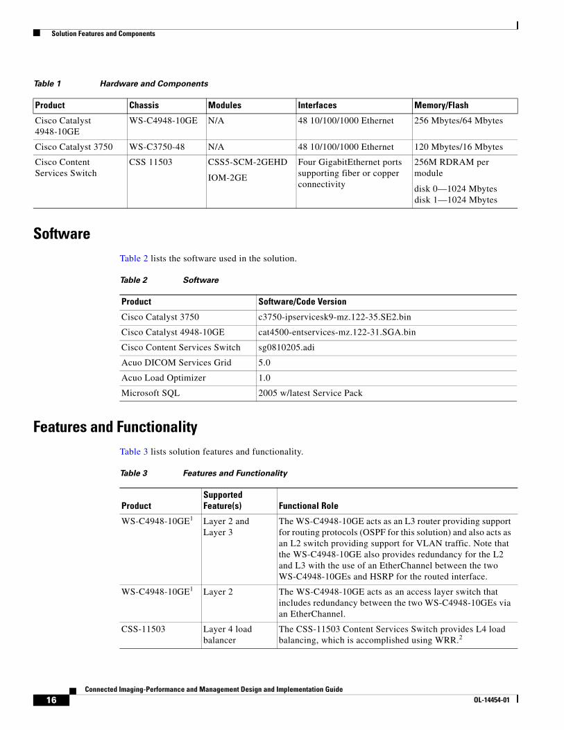
Hardware and ComponentsTable 1 lists the hardware and components used in the solution.
15Connected Imaging-Performance and Management Design and Implementation Guide
The WS-C4948-10GE acts as an L3 router providing support for routing protocols (OSPF for this solution) and also acts as an L2 switch providing support for VLAN traffic. Note that the WS-C4948-10GE also provides redundancy for the L2 and L3 with the use of an EtherChannel between the two WS-C4948-10GEs and HSRP for the routed interface.
WS-C4948-10GE1 Layer 2 The WS-C4948-10GE acts as an access layer switch that includes redundancy between the two WS-C4948-10GEs via an EtherChannel.
CSS-11503 Layer 4 load balancer
The CSS-11503 Content Services Switch provides L4 load balancing, which is accomplished using WRR.2
16Connected Imaging-Performance and Management Design and Implementation Guide
OL-14454-01
Solution Features and Components
Features, Services, and Application Design ConsiderationsNote the following considerations:
• Single point of access to any modality regardless of the location of the PACS system
• Dynamic adaptive load sharing across a DICOM Services Grid
• Easily extensible and expandable without an outage
• Provides a highly available environment
• Store and forward is supported in the case of a PACS or storage outage
Scalability and Capacity Planning Scalability and capacity planning is not part of the overall solution validation process. However, because the solution is based on the Cisco Medical-Grade Network, and a requirement of the solution includes extensibility, scalability is included in the design.
The design includes a pair of Cisco Content Services Switches (CS11503) and multiple Acuo DICOM routers for redundancy. The throughput of the solution is based on the throughput of the CSS and the ability of the Acuo DICOM routers to handle the load.
Total throughput of the CSS is based on the configuration deployed. More information on the throughput possible is available at the following URL: http://www.cisco.com/en/US/products/hw/contnetw/ps792/products_data_sheet0900aecd800f851e.html.
Total throughput of the Acuo DICOM router is based on the hardware platform on which it was deployed, and is affected by factors such as processor type and size, amount of memory, and so on. Additional information on sizing the Acuo DICOM router is available from Acuo Technologies.
AcuoMed Image Manager
DICOM 3.0 Level 2 compliant Image Manager
AcuoMed Manager provides transport, storing, tracking, and retrieving of digital images.
AcuoStore Asset Manager
Digital asset manager
AcuoStore communicates the instructions of AcuoMed with the diverse DICOM storage devices in which digital content is contained.
Acuo Load Optimizer
Monitor service for dynamic load optimization of Content Services Switch
During normal operations, the weights are set equally, usually at 5. From there, the service monitors the queue depth of the servers. As a server becomes congested, the service changes its weight on the CSS to lower than 5 but not lower than 1 (never zero). The value is determined by the amount of depth in the queue that the server is handling. At the same time, the service finds the least congested server and changes the weight value from 5 to 10, depending on the load.
1. Note that other Cisco switches support the listed features and functions similar to the WS-C4948-10GE and may be used, but testing and validation of the solution was performed with the WS-C4948-10GE.
2. Weighted Round Robin (WRR) works similarly to round robin. Round Robin treats all the endpoints (servers) as equals, regardless of the number of connections or response time. WRR uses the performance weight assigned to each endpoint (server) to determine the amount of traffic that is forwarded to each endpoint (server). Endpoints (servers) with a higher weight receive a larger percentage of connections (traffic) at any one time.
Table 3 Features and Functionality (continued)
17Connected Imaging-Performance and Management Design and Implementation Guide
If either of these devices is unable to handle the volume of images being produced by the modalities, the solution allows for the addition of one or more devices to handle the increased load.
High Availability Based on the Cisco Medical-Grade Network, the solution has been designed with high availability in mind.
The solution includes a pair of Cisco Content Services Switches configured in active/passive mode. If the primary fails, the secondary CSS continues directing traffic to the appropriate Acuo DICOM router.
The solution also includes multiple Acuo DICOM routers. The CSS routes traffic to the least-used Acuo DICOM router as determined by the Acuo Load Optimizer service. This service monitors the queues on each of the Acuo DICOM routers and adjusts the weight of each router accordingly in the CSS. If one of the Acuo DICOM routers becomes unavailable, the Load Optimizer removes that router from the rotation by lowering the weight of the device, allowing the others to consume the load.
SecurityAlthough security is not specifically covered in this phase of the solution, there are specific tests to validate that basic access security is in place on each of the devices. Additional security design including path isolation and QoS will be included in future phases.
Implementing and Configuring the Solution
Implementation or Testing Approach
Implementation Overview
This implementation will be used for small clinics, hospitals, image centers, or group cardiology clinics.
What was Implemented/Tested
The following key features and services were implemented:
• Weighted Round Robin L4 load balancing
• CSS XML CLI
• Acuo-to-CSS XML scripting
• HSRP
• L2 EtherChannel and Spanning Tree
• L3 Functionality of the WS-C4948-10GE
• DICOM transporting, tracking, storage, and retrieval
• Active to hot standby failover of the CSSs
18Connected Imaging-Performance and Management Design and Implementation Guide
OL-14454-01
Implementing and Configuring the Solution
What was Not Implemented/Tested
The following were not implemented in this solution:
• Capacity testing
• Performance testing
• CSS active/active (see Caveats and Limitations, page 29 for details)
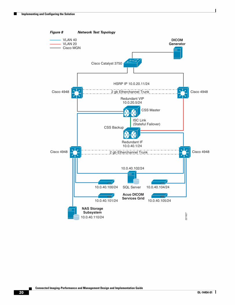
Test Network Topology The network topology is the Cisco Medical-Grade Network with dual connections to the main clinic test site that contains the L4 load balancer and the Acuo DICOM Services Grid. A single connection from the Cisco MGN goes to the remote clinic that contains the test server (acting as a modality or a diagnostic viewer.)
The main site contains the following:
• Redundant L2/L3 switches connected to the Cisco MGN and to the L4 load balancers
• Redundant L4 load balancers
• Redundant access layer switches
• Redundant Acuo services grid
Figure 8 shows the network test topology.
19Connected Imaging-Performance and Management Design and Implementation Guide
OL-14454-01
Implementing and Configuring the Solution
Figure 8 Network Test Topology
Cisco 4948
Cisco MGN
CSS Master
CSS Backup
Acuo DICOMServices Grid
DICOMGenerator
NAS StorageSubsystem
ISC Link(Stateful Failover)
Cisco 4948
Cisco 4948
Cisco Catalyst 3750
Cisco 4948 2 gb Etherchannel Trunk
SQL Server10.0.40.100/24
10.0.40.101/24
10.0.40.110/24
10.0.40.104/24
10.0.40.102/24
Redundant VIP10.0.20.5/24
HSRP IP 10.0.20.11/24
Redundant IF10.0.40.1/24
10.0.40.105/24
2 gb Etherchannel Trunk
2219
27
VLAN 20VLAN 40
20Connected Imaging-Performance and Management Design and Implementation Guide
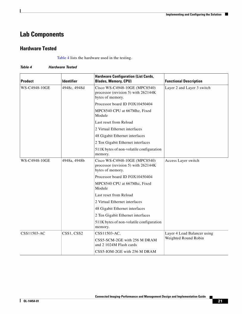
WS-C4948-10GE 4948c, 4948d Cisco WS-C4948-10GE (MPC8540) processor (revision 5) with 262144K bytes of memory.
Processor board ID FOX10450404
MPC8540 CPU at 667Mhz, Fixed Module
Last reset from Reload
2 Virtual Ethernet interfaces
48 Gigabit Ethernet interfaces
2 Ten Gigabit Ethernet interfaces
511K bytes of non-volatile configuration memory.
Layer 2 and Layer 3 switch
WS-C4948-10GE 4948a, 4948b Cisco WS-C4948-10GE (MPC8540) processor (revision 5) with 262144K bytes of memory.
Processor board ID FOX10450404
MPC8540 CPU at 667Mhz, Fixed Module
Last reset from Reload
2 Virtual Ethernet interfaces
48 Gigabit Ethernet interfaces
2 Ten Gigabit Ethernet interfaces
511K bytes of non-volatile configuration memory.
Access Layer switch
CSS11503-AC CSS1, CSS2 CSS11503-AC,
CSS5-SCM-2GE with 256 M DRAM and 2 1024M Flash cards
CSS5-IOM-2GE with 256 M DRAM
Layer 4 Load Balancer using Weighted Round Robin
21Connected Imaging-Performance and Management Design and Implementation Guide
OL-14454-01
Implementing and Configuring the Solution
Software Tested
Table 5 lists the software used in the testing.
Testing Tools
Table 5 lists the testing tools.
Configuration Task ListsThe following information was required before configuration of the equipment (see Table 7):
• Access VLAN for connectivity to the Acuo Services Grid and CSS.
• Upstream VLAN for the CSS.
• IP addresses required:
– IP range for the servers in the Acuo Services Grid and CSS downstream interface
– Default gateway address for the servers in the Acuo Services Grid (which is also the redundant interface IP address on the downstream connection of the CSS)
– IP address for the VIP on the CSS (should be on the VLAN 20 IP address subnet)
HP DL380 Server AcuoMed1, AcuoMed2, AcuoStore1, AcuoStore2, Test Server, SQL
4 Intel Xeon CPUs @ 3.00 Ghz
3.25 G of RAM
Four servers were used for the AcuoMed and AcuoStore tool. One server was used as a test server using only AcuoMed and one server used for the SQL database
22Connected Imaging-Performance and Management Design and Implementation Guide
OL-14454-01
Implementing and Configuring the Solution
– IP address for the redundant interface (in the VLAN 20 IP address subnet) for the upstream connection on the CSS
– IP addresses for the VLAN 20 connections (includes the CSS upstream interface, VLAN 20 interface)
– Obtain the IP addresses from the Cisco MGN
• TCP listening port that is used on the AcuoMed Manager.
• Install AcuoMed and AcuoStore according to the Acuo installation guide on the servers located in the Acuo DICOM Services Grid.
• Install SQL database according to Microsoft installation guide on the server dedicated for the SQL database found in the Acuo services grid. Note this server should be NIC teamed for connectivity to 4948c and 4948d.
Table 7 Configuration Task List
Equipment Configuration Task Command Line
4948a, 4948b Enable IP routing
Configure VLAN 20 interface including HSRP (note: ensure that the VLAN is in the VLAN database)
IP routingInterface vlan 20 Ip address x.x.x.x y.y.y.y Standby 1 ip x.x.x.x Standby 1 timers 1 3 Standby 1 priority 51 Standby 1 preempt delay min 120
Configure routing Router OSPF 10 Network x.x.x.x y.255.255.255 area 10
Configure interface to CSS Interface GE (or) FE x/y/z
Switchport access vlan 20Switchport mode access
Configure interfaces used for the EtherChannel
Interfaces GE or FE x/y/z (must be two interfaces)
Configure circuits Circuit VLAN 20 IP address x.x.x.x IP virtual-router 1 priority 200 IP redundant-interface 1 y.y.y.y Circuit VLAN 40 IP address x.x.x.x IP virtual-router 2 priority 200 IP redundant-interface 2 x.x.x.x
Configure reporter Reporter Farm Type vrid-peering Vrid y.y.y.y 1 Vrid x.x.x.x 2 ActiveReporter Links Type critical-phy-all-up PHY 1/1 PHY 1/2 Active
Configure services Service (name) – note should be a service per server IP address z.z.z.z Port (port number) Redundant-index xxxx Keepalive type tcp Keepalive port (port number) Weight 5 ActiveService upstream-access IP address y.y.y.y
Table 7 Configuration Task List (continued)
24Connected Imaging-Performance and Management Design and Implementation Guide
OL-14454-01
Implementing and Configuring the Solution
Configuration and Menus
Note See Appendix A—Equipment Configurations, page 30.
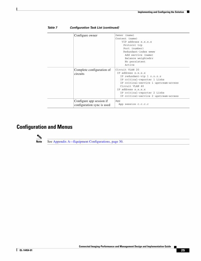
Configure owner Owner (name)Content (name) VIP address x.x.x.x Protocol tcp Port (number) Redundant-index wwww Add service (name) Balance weightedrr No persistent Active
Complete configuration of circuits
Circuit VLAN 20 IP address x.x.x.x IP redundant-vip 1 z.z.z.z IP critical-reporter 1 Links IP critical-service 1 upstream-access Circuit VLAN 40 IP address x.x.x.x IP critical-reporter 2 Links IP critical-service 2 upstream-access
Configure app session if configuration sync is used
App App session c.c.c.c
Table 7 Configuration Task List (continued)
25Connected Imaging-Performance and Management Design and Implementation Guide
OL-14454-01
Implementing and Configuring the Solution
Troubleshooting Configuration
Table 8 Troubleshooting Configuration
Description Command Results
Verify that the EtherChannel is up (4948c, 4948d, 4948a, 4948b)
show etherchannel summary Flags: D - down P - in port-channel I - stand-alone s - suspended H - Hot-standby (LACP only) R - Layer3 S - Layer2 U - in use f - failed to allocate aggregator u - unsuitable for bundling w - waiting to be aggregated d - default port
Number of channel-groups in use: 1Number of aggregators: 1
Group Port-channel Protocol Ports------+-------------+-----------+-----------------------------------------------3 Po3(SU) PAgP Fa1/0/22(P) Fa1/0/23(P)
Verify that HSRP is operational (4948a, 4948b)
sh standby Vlan 20 Vlan20 - Group 1 State is Active 2 state changes, last state change 6w0d Virtual IP address is 10.0.20.10 Active virtual MAC address is 0000.0c07.ac01 Local virtual MAC address is 0000.0c07.ac01 (v1 default) Hello time 1 sec, hold time 3 sec Next hello sent in 0.295 secs Preemption enabled, delay min 120 secs Active router is local Standby router is 10.0.20.12, priority 50 (expires in 2.505 sec) Priority 51 (configured 51) IP redundancy name is "hsrp-Vl20-1" (default)
26Connected Imaging-Performance and Management Design and Implementation Guide
OL-14454-01
Implementing and Configuring the Solution
Verify operational state of the virtual router on the CSS
Sh virtual Virtual-Routers:
Interface Address: 10.0.20.3 VRID: 1 Priority: 200 Config. Priority: 200 State: Master Master IP: 10.0.20.3 State Changes: 2 Last Change: 04/18/2007 09:06:13 Preempt: False Last Fail Reason: No Failure Last Clearing of Stat Counters: 04/18/2007 09:06:05
Critical-Services: upstream-access State: Alive Type: Local
Critical-Reporters: Links State: Up Type: critical-phy-all-up
Interface Address: 10.0.40.3 VRID: 2 Priority: 200 Config. Priority: 200 State: Master Master IP: 10.0.40.3 State Changes: 2 Last Change: 04/18/2007 09:06:13 Preempt: False Last Fail Reason: No Failure Last Clearing of Stat Counters: 04/18/2007 09:06:05 Critical-Services: upstream-access State: Alive Type: Local
Critical-Reporters: Links State: Up Type: critical-phy-all-up
Table 8 Troubleshooting Configuration (continued)
27Connected Imaging-Performance and Management Design and Implementation Guide
OL-14454-01
Implementing and Configuring the Solution
Verify rules and services are operational on the CSS
Sh rule Content Rules:
Name: L3_Rule Owner: L3_OwnerState: Active Type: HTTPBalance: Weighted Round Robin Failover: N/APersistence: Disabled Param-Bypass: DisabledSession Redundancy: Enabled Redundancy Global Index: 1102IP Redundancy: MasterL3: 10.0.20.5L4: TCP/4321Url: Redirect: ""TCP RST client if service unreachable: DisabledRule Services and Weights: 1: AcuoMed1-Alive, S-5 2: AcuoMed2-Alive, S-5 3: AcuoStore1-Alive, S-5 4: AcuoStore2-Alive, S-5
Verify app is operational on the CSS
Sh app APP CONFIGURATION: Enabled PortNumber: 5001 MaxFrameSize: 10240
Verify status of the reporter
Sh reporter Reporters (2 entries):
Name: Farm State: Master Type: vrid-peering State Transitions: 3 Last Clearing of Stat Counters: 04/18/2007 09:06:05
Circuit VRID State 10.0.20.3 1 Master 10.0.40.3 2 Master
Name: Links State: Up Type: critical-phy-all-up State Transitions: 2 Last Clearing of Stat Counters: 04/18/2007 09:06:05
Interface Link 1/1 Up 1/2 Up
Table 8 Troubleshooting Configuration (continued)
28Connected Imaging-Performance and Management Design and Implementation Guide
OL-14454-01
Implementing and Configuring the Solution
Results and ConclusionsThe testing verified the following:
• Traffic from modality was sent to the storage system using the Acuo DICOM Services Grid.
• Traffic connections were balanced by the integration of the CSS and the Acuo Load Optimizer service.
• The customer has to manually manage the destination address on all of their modalities. With the Connected Imaging-Performance and Management solution in place, that destination address is the same for all modalities, regardless of the location of the storage system. It effectively allows the modality to be updated a single time while destination changes can be managed centrally within the Acuo DICOM Services Grid.
• Without the implementation of the Connected Imaging-Performance and Management solution, there exist multiple single points of failure in an imaging environment. This effectively eliminates the single points of failure from a storage perspective.
Caveats and LimitationsCaveats, limitations, and workarounds are as follows:
• Component (hardware/software) limitation—The maximum concurrent connections per I/O module are 200,000 with 256 MB DRAM, and the maximum supported keepalives are 2048 when using the WebNS Software Version 8.10.
– Workaround or resolution—N/A
• The Acuo Load Optimizer can run only on a single Acuo DICOM router at a time. It typically runs on the primary router in the DICOM Services Grid; however, it can be installed on multiple routers at the same time.
– Workaround or resolution—If the router where the Acuo Load Optimizer is running fails, or if the service itself fails, it must be manually restarted on an alternate DICOM router.
• Inter-switch communications (ISC) link
– Workaround or resolution—Only one ISC link is allowed per paired CSS
• Weighted Round Robin algorithm on the Content Services Switch (11503) works in the following manner:
If Server A and Server B are weighted as 4, and server C is weighted as 3, the Content Services Switch sends 4 connections to Server A, 4 Connections to Server B, and 3 connections to Server C, then starts the process again. At the end of 11 connections, the connection count look like AAAABBBBCCC.
– Workaround or resolution—The algorithm does not evenly place the connections to the servers; instead, it follows the weights and sends the number of connections to the server based on the weight. Over time, this balances out and provides higher service levels to the overall radiology systems.
This is masked somewhat by the Acuo Load Optimize because it monitors the load on the server queues and updates the weight tables accordingly.
• Windows Server Network Interface Cards (NIC) and Cisco switches—Auto-negotiation between a Cisco switch and a NIC on a Windows Server may not always succeed or may cause delays in traffic response times. This is a known Windows issue.
29Connected Imaging-Performance and Management Design and Implementation Guide
OL-14454-01
Appendix A—Equipment Configurations
– Workaround or resolution—To work around this problem, leave either the Cisco switch or the Windows NIC to auto-negotiate and manually set the speed and the duplex values of the other component.
• Active/active configuration of the CSSs—The active/active design was not tested because of the issues that would arise in a customer environment if deployed. Active/active would require that the modalities either be pointed to both VIPs seen on the individual CSSs or use a masked IP with DNS match.
Pointing the modalities to both VIPs seen on the CSSs—The modalities could forward traffic to a downed VIP. To ensure traffic flow, manual intervention would be required by the user to change the target IP to the currently active VIP if the other was down.
Using a masked IP with DNS match—DNS would try to resolve a possible downed VIP until it ages out, which it will then forward traffic to the other supported VIP found in the DNS table
– Workaround or resolution—None.
Appendix A—Equipment ConfigurationsThe equipment configurations listed here are intended to serve as examples for the concepts relevant to this solution.
4948A and 4948B (L2/L3 switches)4948a#sh runBuilding configuration...
Current configuration : 3120 bytes!version 12.2no service padservice timestamps debug uptimeservice timestamps log uptimeno service password-encryptionservice compress-config!hostname 4948a!boot-start-markerboot-end-marker!!no aaa new-modelip subnet-zero!vtp domain ciscovtp mode transparent!!! power redundancy-mode redundantno file verify autospanning-tree mode pvstspanning-tree extend system-id!vlan internal allocation policy ascending!
30Connected Imaging-Performance and Management Design and Implementation Guide
OL-14454-01
Appendix A—Equipment Configurations
vlan 20 !interface Port-channel3Configuration for etherchannel switchport switchport trunk encapsulation dot1q switchport trunk allowed vlan 1,20 switchport mode trunk!interface GigabitEthernet1/1Connection to the Cisco MGN no switchport ip address 10.2.2.1 255.255.255.0!i!interface GigabitEthernet1/22etherchannel port switchport trunk encapsulation dot1q switchport trunk allowed vlan 1,20 switchport mode trunk channel-group 3 mode desirableThis is the only command line required the rest will populate with the port-channel config!interface GigabitEthernet1/23etherchannel port switchport trunk encapsulation dot1q switchport trunk allowed vlan 1,20 switchport mode trunk channel-group 3 mode desirableThis is the only command line required the rest will populate with the port-channel config!!interface GigabitEthernet1/47Connection to the CSS switchport access vlan 20 switchport mode access!interface GigabitEthernet1/48 switchport access vlan 5 switchport mode access!interface TenGigabitEthernet1/49!interface TenGigabitEthernet1/50!interface Vlan1 no ip address!interface Vlan20 description Clientside ip address 10.0.20.11 255.255.255.0 standby 1 ip 10.0.20.10HSRP configuration standby 1 timers 1 3 standby 1 priority 51 standby 1 preempt delay minimum 120!router ospf 10 log-adjacency-changes redistribute static metric 1 subnets network 10.0.0.0 0.255.255.255 area 10!ip route 10.0.40.0 255.255.255.0 10.0.20.5ip http server!!!!!!
31Connected Imaging-Performance and Management Design and Implementation Guide
OL-14454-01
Appendix A—Equipment Configurations
control-plane!!line con 0 stopbits 1line vty 0 4 no loginline vty 5 15 no login!
4948b#sh runBuilding configuration...
Current configuration : 3120 bytes!version 12.2no service padservice timestamps debug uptimeservice timestamps log uptimeno service password-encryptionservice compress-config!hostname 4948b!boot-start-markerboot-end-marker!!no aaa new-modelip subnet-zero!vtp domain ciscovtp mode transparent!!! power redundancy-mode redundantno file verify autospanning-tree mode pvstspanning-tree extend system-id!vlan internal allocation policy ascending!vlan 20 !interface Port-channel3Configuration for etherchannel switchport switchport trunk encapsulation dot1q switchport trunk allowed vlan 1,20 switchport mode trunk!interface GigabitEthernet1/1Connection to the Cisco MGN no switchport ip address 10.3.3.1 255.255.255.0!i!interface GigabitEthernet1/22etherchannel port switchport trunk encapsulation dot1q switchport trunk allowed vlan 1,20 switchport mode trunk
32Connected Imaging-Performance and Management Design and Implementation Guide
OL-14454-01
Appendix A—Equipment Configurations
channel-group 3 mode desirableThis is the only command line required the rest will populate with the port-channel config!interface GigabitEthernet1/23etherchannel port switchport trunk encapsulation dot1q switchport trunk allowed vlan 1,20 switchport mode trunk channel-group 3 mode desirableThis is the only command line required the rest will populate with the port-channel config!!interface GigabitEthernet1/47Connection to the CSS switchport access vlan 20 switchport mode access!interface GigabitEthernet1/48 switchport access vlan 5 switchport mode access!interface TenGigabitEthernet1/49!interface TenGigabitEthernet1/50!interface Vlan1 no ip address!interface Vlan20 description Clientside ip address 10.0.20.12 255.255.255.0 standby 1 ip 10.0.20.10HSRP configuration standby 1 timers 1 3 standby 1 priority 50 standby 1 preempt delay minimum 120!router ospf 10 log-adjacency-changes redistribute static metric 1 subnets network 10.0.0.0 0.255.255.255 area 10!ip route 10.0.40.0 255.255.255.0 10.0.20.5ip http server!!!!!!control-plane!!line con 0 stopbits 1line vty 0 4 no loginline vty 5 15 no login!
33Connected Imaging-Performance and Management Design and Implementation Guide
OL-14454-01
Appendix A—Equipment Configurations
CSS1 and CSS2 (L4 Load-Balancer)CSS1# sh run!Generated on 04/14/2007 05:16:16!Active version: sg0810205
configure
!*************************** GLOBAL *************************** no restrict xml Allows XML CLI commands no restrict web-mgmt global-portmap base-port 34000 range 30000
app app session 10.0.20.2 Allows for Configuration sync
ip address 10.0.20.3 255.255.255.0 ip virtual-router 1 priority 200 VRRP configuration ip redundant-interface 1 10.0.20.4 Physical interface redundancy ip redundant-vip 1 10.0.20.5 Virtual interface redundancy ip critical-reporter 1 Links Interface for tracking failover ip critical-service 1 upstream-access Interface for tracking failover
circuit VLAN40 Downstream interface
ip address 10.0.40.3 255.255.255.0 ip virtual-router 2 priority 200 VRRP configuration ip redundant-interface 2 10.0.40.1 Physical interface redundancy ip critical-service 2 upstream-access Interface for tracking failover ip critical-reporter 2 Links Interface for tracking failover !************************** REPORTER **************************reporter Farm type vrid-peering vrid 10.0.40.3 2 vrid 10.0.20.3 1 active
reporter Links type critical-phy-all-up phy 1/1 phy 1/2
34Connected Imaging-Performance and Management Design and Implementation Guide
OL-14454-01
Appendix A—Equipment Configurations
active
!************************** SERVICE **************************service AcuoMed1 ip address 10.0.40.100 port 4321 redundant-index 1001 keepalive type tcp keepalive port 4321 weight 5 active
service AcuoMed2 redundant-index 1003 ip address 10.0.40.104 port 4321 weight 5 keepalive type tcp keepalive port 4321 active
service AcuoStore1 redundant-index 1002 ip address 10.0.40.101 port 4321 weight 5 keepalive type tcp keepalive port 4321 active
service AcuoStore2 redundant-index 1004 ip address 10.0.40.105 port 4321 weight 5 keepalive type tcp keepalive port 4321 active
service upstream-access ip address 10.0.20.10 active
content L3_Rule vip address 10.0.20.5 protocol tcp port 4321 redundant-index 1102 add service AcuoMed1 add service AcuoMed2 add service AcuoStore1 add service AcuoStore2 balance weightedrr no persistent active
CSS2# sh run !Generated on 04/14/2007 06:16:29!Active version: sg0810205
35Connected Imaging-Performance and Management Design and Implementation Guide
OL-14454-01
Appendix A—Equipment Configurations
configure
!*************************** GLOBAL *************************** global-portmap base-port 34000 range 30000 no restrict xml no restrict web-mgmt
ip address 10.0.20.2 255.255.255.0 ip virtual-router 1 priority 200 ip redundant-vip 1 10.0.20.5 ip redundant-interface 1 10.0.20.4 ip critical-service 1 upstream-access ip critical-reporter 1 Links
circuit VLAN40
ip address 10.0.40.2 255.255.255.0 ip virtual-router 2 priority 200 ip redundant-interface 2 10.0.40.1 ip critical-service 2 upstream-access ip critical-reporter 2 Links !************************** REPORTER **************************reporter Farm type vrid-peering vrid 10.0.40.2 2 vrid 10.0.20.2 1 active
reporter Links type critical-phy-all-up phy 1/1 phy 1/2 active
!************************** SERVICE **************************service AcuoMed1 ip address 10.0.40.100 port 4321 redundant-index 1001
36Connected Imaging-Performance and Management Design and Implementation Guide
OL-14454-01
Appendix A—Equipment Configurations
weight 5 active
service AcuoMed2 redundant-index 1003 ip address 10.0.40.104 port 4321 weight 5 active
service AcuoStore1 redundant-index 1002 ip address 10.0.40.101 port 4321 weight 5 active
service AcuoStore2 redundant-index 1004 ip address 10.0.40.105 port 4321 weight 5 active
service upstream-access ip address 10.0.20.10 active
content L3_Rule vip address 10.0.20.5 protocol tcp port 4321 balance weightedrr add service AcuoMed1 add service AcuoMed2 add service AcuoStore1 add service AcuoStore2 redundant-index 1102 active
4948C and 4948D (Access Switch)4948c#sh runBuilding configuration...
Current configuration : 3370 bytes!version 12.2no service padservice timestamps debug uptimeservice timestamps log uptimeno service password-encryptionservice compress-config!hostname 4948c!boot-start-markerboot-end-marker!
37Connected Imaging-Performance and Management Design and Implementation Guide
38Connected Imaging-Performance and Management Design and Implementation Guide
OL-14454-01
Appendix A—Equipment Configurations
!interface GigabitEthernet1/47etherchannel port switchport trunk encapsulation dot1q switchport trunk allowed vlan 1,40 switchport mode trunk channel-group 5 mode desirable non-silentThis is the only command line required the rest will populate with the port-channel config!
interface Vlan1 no ip address!interface Vlan40 no ip address! ip default-gateway 10.0.40.1ip route 0.0.0.0 0.0.0.0 10.0.40.1ip http server!!control-plane!!line con 0 stopbits 1line vty 0 4 loginline vty 5 15 login!end
4948d#sh runBuilding configuration...
Current configuration : 3370 bytes!version 12.2no service padservice timestamps debug uptimeservice timestamps log uptimeno service password-encryptionservice compress-config!hostname 4948c!boot-start-markerboot-end-marker!!no aaa new-modelip subnet-zero!vtp domain ciscovtp mode transparent!!! power redundancy-mode redundantno file verify autospanning-tree mode pvstspanning-tree extend system-id!
39Connected Imaging-Performance and Management Design and Implementation Guide
OL-14454-01
Appendix A—Equipment Configurations
vlan internal allocation policy ascending!vlan 40,103 !interface Port-channel5Configuration for etherchannel switchport switchport trunk encapsulation dot1q switchport trunk allowed vlan 1,40 switchport mode trunk!interface GigabitEthernet1/1 switchport access vlan 40 switchport mode access speed 100 duplex full!interface GigabitEthernet1/2 switchport access vlan 40 switchport mode access speed 100 duplex full!interface GigabitEthernet1/3 switchport access vlan 40 switchport mode access speed 100 duplex full!interface GigabitEthernet1/4 switchport access vlan 40 switchport mode access speed 100 duplex full!interface GigabitEthernet1/5!interface GigabitEthernet1/6 switchport access vlan 40 switchport mode access!interface GigabitEthernet1/45Connection to the CSS switchport access vlan 40 switchport mode access!interface GigabitEthernet1/46etherchannel port switchport trunk encapsulation dot1q switchport trunk allowed vlan 1,40 switchport mode trunk channel-group 5 mode desirable non-silentThis is the only command line required the rest will populate with the port-channel config!interface GigabitEthernet1/47etherchannel port switchport trunk encapsulation dot1q switchport trunk allowed vlan 1,40 switchport mode trunk channel-group 5 mode desirable non-silentThis is the only command line required the rest will populate with the port-channel config!
interface Vlan1 no ip address!interface Vlan40 no ip address
40Connected Imaging-Performance and Management Design and Implementation Guide
Appendix B—DICOM Header InformationThe following information is from http://www.sph.sc.edu/comd/rorden/dicom.html and is provided for informational purposes.
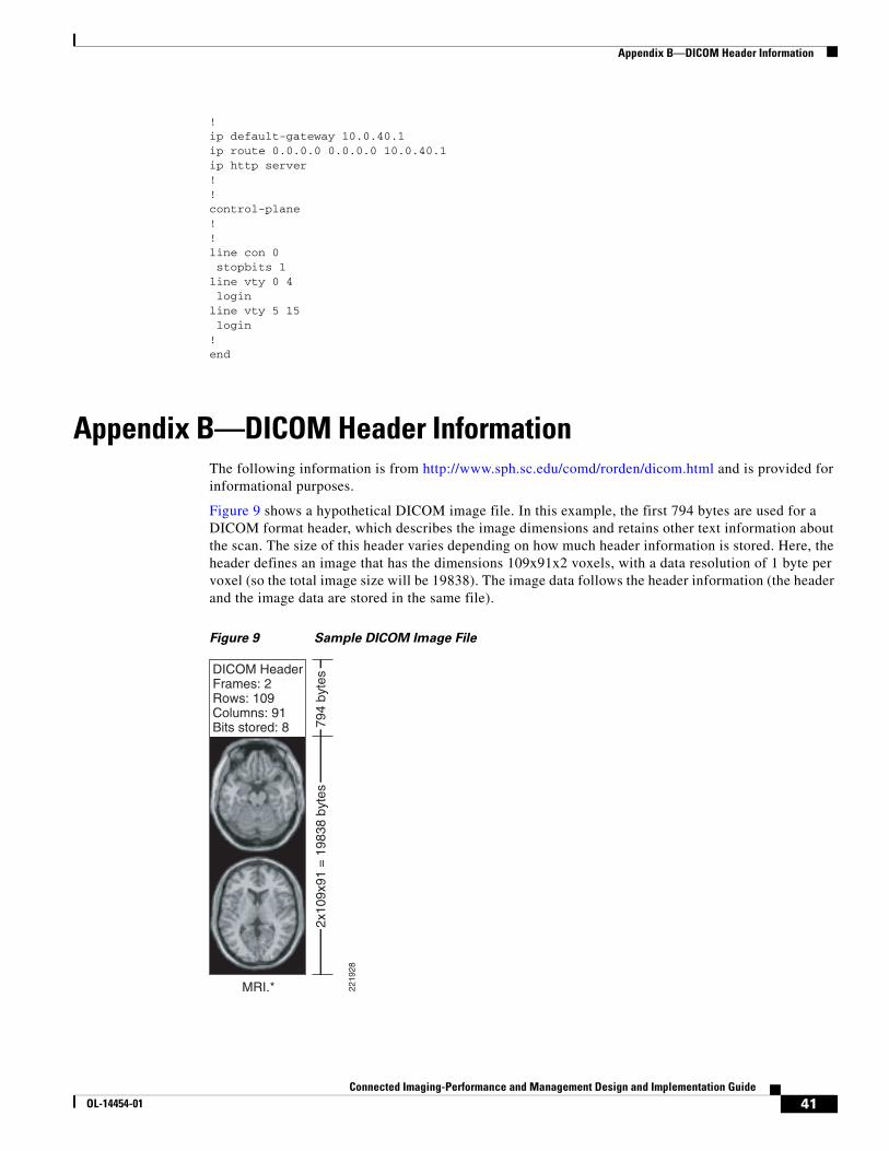
Figure 9 shows a hypothetical DICOM image file. In this example, the first 794 bytes are used for a DICOM format header, which describes the image dimensions and retains other text information about the scan. The size of this header varies depending on how much header information is stored. Here, the header defines an image that has the dimensions 109x91x2 voxels, with a data resolution of 1 byte per voxel (so the total image size will be 19838). The image data follows the header information (the header and the image data are stored in the same file).
Figure 9 Sample DICOM Image File
MRI.*
2x10
9x91
= 1
9838
byt
es79
4 by
tesDICOM Header
Frames: 2Rows: 109Columns: 91Bits stored: 8
2219
28
41Connected Imaging-Performance and Management Design and Implementation Guide
Figure 10 shows a more detailed list of the DICOM header, as displayed by the software. Note that DICOM requires a 128-byte preamble (these 128 bytes are usually all set to zero), followed by the letters “D”, “I”, “C”, and “M”. This is followed by the header information, which is organized in “groups”. For example, the group 0002hex is the file meta information group, and (in the example on the left) contains three elements: one defines the group length, one stores the file version, and the third stores the transfer syntax.
Figure 10 DICOM Header
The DICOM elements required depend on the image type, and are listed in Part 3 of the DICOM standard. For example, this image modality is “MR” (see group:element 0008:0060), so it should have elements to describe the MRI echo time. The absence of this information in this image is a violation of the DICOM standard. In practice, most DICOM format viewers (including MRIcro and ezDICOM) do not check for the presence of most of these elements, extracting only the header information that describes the image size.
The NEMA standard preceded DICOM, and the structure is very similar, with many of the same elements. The main difference is that the NEMA format does not have the 128-byte data offset buffer or the lead characters “DICM”. In addition, NEMA did not explicitly define multi-frame (3D) images, so element 0028,0008 was not present.
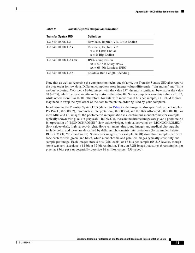
Of particular importance is group:element 0002:0010. This defines the Transfer Syntax Unique Identification (see Table 9). This value reports the structure of the image data, revealing whether the data has been compressed. Note that many DICOM viewers can handle only uncompressed raw data. DICOM images can be compressed both by the common lossy JPEG compression scheme (where some high frequency information is lost) as well as a lossless JPEG scheme that is rarely seen outside of medical imaging (this is the original and rare Huffman lossless JPEG, not the more recent and efficient JPEG-LS algorithm). These codes are described in Part 5 of the DICOM standard (ftp://medical.nema.org/medical/dicom/2000/draft/). A nice introduction to this transfer syntax is provided at http://www.barre.nom.fr.
First 128 bytes: unused by DICOM formatFollowed by the characters ‘D’,’I’,’C’,’M’This preamble is followed by extra information e.g.:
0002,0000,File Meta Elements Group Len: 1320002,0001,File Meta Info Version: 2560002,0010, Transfer Syntax UID: 1.2.840.10008.1.2.1.0008,0000,Identifying Group Length: 1520008,0060,Modality: MR0008,0070,Manufacturer: MRIcro0018,0000,Acquisition Group Length: 280018,0050,Slice Thickness: 2.000018,1020,Software Version: 46\64\370028,0000,Image Presentation Group Length: 1480028,0001,Samples Per Pixel: 10028,0004,Photometric Interpretation: MONOCHROME2.0028,0008,Number of Frames: 20028,0010,Rows: 1090028,0011,Columns: 910028,0030,Pixel Spacing: 2.00\2.000028,0100,Bits Allocated: 80028,0101,Bits Stored: 80028,0102,High Bit: 70028,0103,Pixel Representation: 00028,1052,Rescale Intercept: 0.000028,1053,Rescale Slope: 0.003921577FE0,0000,Pixel Data Group Length: 198507FE0,0010,Pixel Data: 19838 22
1929
42Connected Imaging-Performance and Management Design and Implementation Guide
Note that as well as reporting the compression technique (if any), the Transfer Syntax UID also reports the byte order for raw data. Different computers store integer values differently: “big endian” and “little endian” ordering. Consider a 16-bit integer with the value 257: the most significant byte stores the value 01 (=255), while the least significant byte stores the value 02. Some computers save this value as 01:02, while others store it as 02:01. Therefore, for data with more than 8 bits per sample, a DICOM viewer may need to swap the byte order of the data to match the ordering used by your computer.
In addition to the Transfer Syntax UID (shown in Table 9), the image is also specified by the Samples Per Pixel (0028:0002), Photometric Interpretation (0028:0004), and the Bits Allocated (0028:0100). For most MRI and CT images, the photometric interpretation is a continuous monochrome (for example, typically shown with pixels in grayscale). In DICOM, these monochrome images are given a photometric interpretation of “MONOCHROME1” (low values=bright, high values=dim) or “MONOCHROME2” (low values=dark, high values=bright). However, many ultrasound images and medical photographs include color, and these are described by different photometric interpretations (for example, Palette, RGB, CMYK, YBR, and so on). Some color images (for example, RGB) store three samples per pixel (one each for red, green, and blue), while monochrome and paletted images typically store only one sample per image. Each images store 8 bits (256 levels) or 16 bits per sample (65,535 levels), though some scanners save data in 12-bit or 32-bit resolution. Thus, an RGB image that stores three samples per pixel at 8 bits per can potentially describe 16 million colors (256 cubed).
Table 9 Transfer Syntax Unique Identification
Transfer Syntax UID Definition
1.2.840.10008.1.2 Raw data, Implicit VR, Little Endian
1.2.840.10008.1.2.x Raw data, Explicit VR x = 1: Little Endian x = 2: Big Endian
1.2.840.10008.1.2.4.xx JPEG compression xx = 50-64: Lossy JPEG xx = 65-70: Lossless JPEG
1.2.840.10008.1.2.5 Lossless Run Length Encoding
43Connected Imaging-Performance and Management Design and Implementation Guide
OL-14454-01
Appendix B—DICOM Header Information
44Connected Imaging-Performance and Management Design and Implementation Guide