University of Kentucky University of Kentucky UKnowledge UKnowledge Center for Applied Energy Research Faculty Patents Center for Applied Energy Research 1-27-2015 Contaminant-Tolerant Solvent and Stripping Chemical and Contaminant-Tolerant Solvent and Stripping Chemical and Process for Using Same for Carbon Capture from Combustion Process for Using Same for Carbon Capture from Combustion Gases Gases Kunlei Liu University of Kentucky, [email protected]James K. Neathery University of Kentucky Joseph E. Remias University of Kentucky Follow this and additional works at: https://uknowledge.uky.edu/caer_patents Part of the Engineering Commons Right click to open a feedback form in a new tab to let us know how this document benefits you. Right click to open a feedback form in a new tab to let us know how this document benefits you. Recommended Citation Recommended Citation Liu, Kunlei; Neathery, James K.; and Remias, Joseph E., "Contaminant-Tolerant Solvent and Stripping Chemical and Process for Using Same for Carbon Capture from Combustion Gases" (2015). Center for Applied Energy Research Faculty Patents. 5. https://uknowledge.uky.edu/caer_patents/5 This Patent is brought to you for free and open access by the Center for Applied Energy Research at UKnowledge. It has been accepted for inclusion in Center for Applied Energy Research Faculty Patents by an authorized administrator of UKnowledge. For more information, please contact [email protected].
Transcript
University of Kentucky University of Kentucky
UKnowledge UKnowledge
Center for Applied Energy Research Faculty Patents Center for Applied Energy Research
1-27-2015
Contaminant-Tolerant Solvent and Stripping Chemical and Contaminant-Tolerant Solvent and Stripping Chemical and
Process for Using Same for Carbon Capture from Combustion Process for Using Same for Carbon Capture from Combustion
Follow this and additional works at: https://uknowledge.uky.edu/caer_patents
Part of the Engineering Commons
Right click to open a feedback form in a new tab to let us know how this document benefits you. Right click to open a feedback form in a new tab to let us know how this document benefits you.
Recommended Citation Recommended Citation Liu, Kunlei; Neathery, James K.; and Remias, Joseph E., "Contaminant-Tolerant Solvent and Stripping Chemical and Process for Using Same for Carbon Capture from Combustion Gases" (2015). Center for Applied Energy Research Faculty Patents. 5. https://uknowledge.uky.edu/caer_patents/5
This Patent is brought to you for free and open access by the Center for Applied Energy Research at UKnowledge. It has been accepted for inclusion in Center for Applied Energy Research Faculty Patents by an authorized administrator of UKnowledge. For more information, please contact [email protected].
The Engineering ToolBox, “WateriThermal Properties.” (no date) Viewed on May 5, 2014 at http://WWW.engineeringt001b0xcom/wa ter-thermal-properties-di162 .html.* Dawson, Jr, et al., “Volumetric Behavior, Vapor Pressures, and Criti cal Properties of Neopentane.” J. Chem. Eng. Data, v01. 18, N0. 1 (1973), pp. 7-15.*
* cited by examiner
Primary Examiner * Stanley Silverman
Assistant Examiner * Daniel Berns
(74) Attorney, Agent, or Firm * King & Schickli, PLLC
(57) ABSTRACT
A contaminant-tolerant hybrid scrubbing solvent is provided for post-combustion CO2 capture and removal, the scrubbing solvent including an amine and a low fraction of ammonia. A stripping carrier having a low latent energy is included for solvent regeneration. In one embodiment, the amine is MEA and the stripping chemical having low latent energy is pen tane or an isomer thereof. Processes and apparatus for CO2 removal from post-combustion gases and for solvent regen eration are described.
m8 “M2 \lim ............ I . l- ............ l \w,
4% km
1,35 .0ng 6:30 & .... .. $21 1%! 1w ,,,, ., C E E Ql\h 3%
US 8,940,261 B2 1
CONTAMINANT-TOLERANT SOLVENT AND STRIPPING CHEMICAL AND PROCESS FOR USING SAME FOR CARBON CAPTURE
FROM COMBUSTION GASES
This application claims priority to US. Provisional Patent Application Ser. No. 61/388,340 ?led 30 Sep. 2010, the entire disclosure of which is incorporated herein by reference.
TECHNICAL FIELD
The present disclosure relates to a contaminant-tolerant solvent/stripping chemical hybrid, i.e. a scrubbing solvent, and to a process for its use. In particular, the disclosure relates to use of a solvent mixture of an amine and a low concentra
tion of ammonia (NH3) for CO2 removal, and a chemical having a low latent energy as a stripping carrier within a desorber for solvent regeneration. The process and solvent ?nd utility in post-combustion carbon dioxide (CO2) capture, such as from utility ?ue gases in coal-?red power plants.
BACKGROUND OF THE INVENTION
In a typical coal-?red power plant, coal is burned in a boiler to make high temperature and pres sure steam to drive a steam turbine and electricity generator. For the steam-side process, the initial superheated steam drives the high-pressure turbine ?rst for power generation, before returning to the boiler for reheating to bring steam temperature back to over 540° C. (according to the steam cycle speci?cations and boiler design). The reheated steam then enters intermediate-pres sure and low-pressure turbines to generate additional elec tricity. The steam pipe connecting the intermediate-pressure turbine exhaust and the low-pressure turbine inlet is called the cross-over section, where the steam for solvent regeneration in the CO2 capture process is extracted. The exiting saturated steam from the low-pressure turbine is condensed in a water to-steam heat exchanger (or condenser). The condensate is pressurized via feedwater pumps, heated via feedwater heat ers and economizers, and fed back to the boiler to complete the steam cycle.
For the gas-side process, typically after combustion of the coal in low NOx burners the combustion gases leave the boiler and are treated in a NOx removal device called a Selective Catalytic Reduction (SCR). After the SCR treatment, the gas is further treated in a ?y ash removal device, such as an electrostatic precipitator, to remove particulates. After this treatment, the gas is routed through an SO2 removal device (SO2 scrubber). At this point, the carbon capture process begins.
It is known in the art to use scrubbing solvents for capturing CO2 from post-combustion gases, such as from utility ?ue gases. As an example, a conventional solvent often used is 30 weight percent monoethanolamine (MEA). Likewise, it is known to use solvents comprising KZCO3/KHCO3 or NH3. Such conventional solvents, while generally effective for their intended purpose, can be markedly improved in terms of CO2 adsorption and recovery, required operating tempera tures, energy requirements, and the like.
To solve the aforementioned and other problems, the present disclosure provides a mixed solvent including an amine and a low fraction of ammonia for CO2 removal, and further provides a stripping carrier having a low latent energy for solvent regeneration. Likewise, herein is disclosed a pro cess for using the mixed solvent/stripping carrier in post combustion CO2 capture. This mixed solvent provides mul tiple advantages, including: (1) higher mass-transfer ?ux
20
25
30
35
40
45
50
55
60
65
2 which results in a smaller absorber to capture the same amount of CO2 from the ?ue gas stream; (2) higher carbon capacity, which reduces the liquid recycling rate between the absorber and the stripper, increases CO2 dissociated partial pressure and reduces the stripper size; and (3) less energy demand for CO2 stripping. The ammonia (i) reduces sulfur dioxide (S02) levels in the pre-treatment tower to a suitable concentration to minimize MEA degradation; (ii) acts (in vapor form) as a carrier gas which reduces CO2 vapor pres sure in the stripper; and (iii) enhances reaction kinetics and increases the solvent capacity.
SUMMARY OF THE INVENTION
In accordance with the purposes and advantages of the present invention as described herein, in one aspect of the present disclosure a contaminant-tolerant solvent/stripping chemical hybrid process is described. The process uses a mixture of an amine and a low fraction of ammonia as reagents for C2 removal, and also uses a chemical with a low latent energy as a stripping carrier for solvent regeneration, all for post-combustion CO2 capture. In one embodiment, the amine is MEA. Other suitable amines are contemplated, including without limitation 2-Amino-2-methylpropanol (AMP), methyldiethanolamine (MDEA), Piperazine (PZ), Diglycolamine (DGA), Ethylenediamine (EDA), Tri(Hy droxymethyl)Aminomethane (THAM), Diethanolamine (DEA), DIPA (di-isopropanolamine), and amino acids.
Inclusion of a low fraction of ammonia minimizes ammo nia slip, for example in scrubber and stripper exhaust streams. Ammonia reduces SO2 levels in pretreatment processes to a suitable concentrations, minimizing MEA degradation according to the reaction:
The resulting solution can then be cooled, whereby the sulfate solids precipitate and can be removed. In turn, ammonia vapor acts as a carrier gas. Since the stripper temperature is above 60° C., ammonium carbon-compounds will dissociate into NH3, CO2 and H20 which will reduce the CO2 vapor pressure in a stripper.
Broadly, any suitable stripping carrier having low latent energy is contemplated, with the proviso that stripping carri ers having the properties of immiscibility in water and a latent heat/heat of vaporization less than that of water are contem plated. Generally, such compounds having a normal boiling point range less than 90° C. are contemplated. In one embodi ment, pentane or isomers thereof, including without limita tion n-pentane and iso-pentane, and/or n-hexane are used as the stripping carrier. Compared to conventional solvents for CO2 capture, the present hybrid solvent provides a higher mass-transfer ?ux in the conventional working carbon load ing range; an increased actual carbon capacity, and a reduced energy demand for CO2 stripping.
In turn, in another aspect of the present disclosure, a pro cess for stripping CO2 from post-combustion gases, for example from utility ?ue gases emanating from coal-?red power plants, is provided utilizing the above mixed solvent. Advantageously, the present technology readily incorporates into existing infrastructure.
In the following description there are shown and described several different embodiments, simply by way of illustration of some of the modes best suited to carry out the invention. As
US 8,940,261 B2 3
it will be realized, the described subject matter is capable of other different embodiments and its several details are capable of modi?cation in various, obvious aspects all with out departing from the invention. Accordingly, the drawings and descriptions will be regarded as illustrative in nature and not as restrictive.
BRIEF DESCRIPTION OF THE DRAWINGS
The accompanying drawings incorporated herein and forming a part of the speci?cation, illustrate several aspects of the present invention and together with the description serve to explain certain principles of the invention. In the drawings:
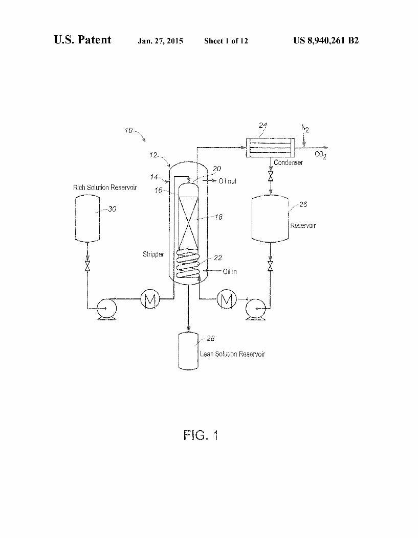
FIG. 1 schematically shows a laboratory scale CO2 strip ping apparatus according to the present disclosure;
FIG. 2 graphically depicts carbon loading for successive CO2 stripping cycles using 5 M MEA solvent at 90° C.;
FIG. 3 graphically depicts carbon loading for successive CO2 stripping cycles using 5 M MEA solvent at 100° C.;
FIG. 4 graphically depicts carbon loading for successive CO2 stripping cycles using 5 M MEA solvent at 82° C. and 90° C. for carrier and control experiments;
FIG. 5 graphically percentage of CO2 stripped from 5 M MEA solvent as a function of loading (a) at the end of the stripping cycles at 82° C. and 90° C., with the starting solvent a being 0.45 for each experiment;
FIG. 6 shows kinetics of CO2 adsorption by four solvent compositions;
FIG. 7 presents comparison data from conventional MEA solvent (30 wt %) versus a solvent composition according to the present disclosure under varying operating conditions;
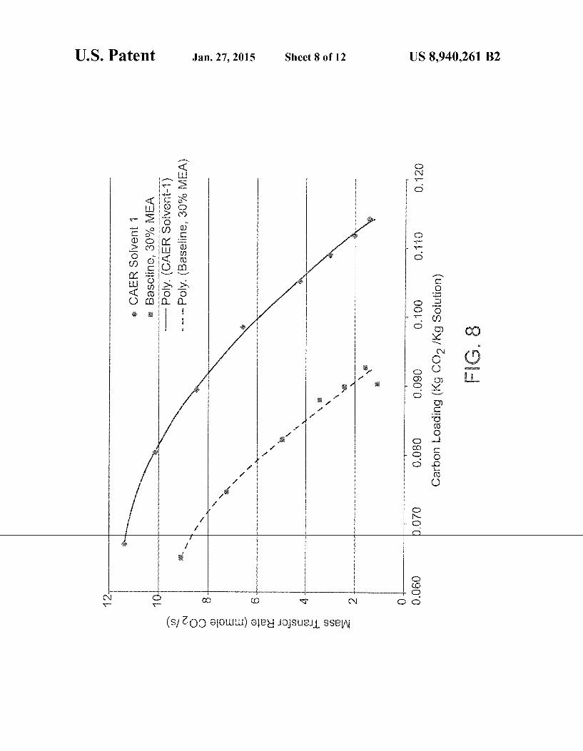
FIG. 8 presents comparison data for CO2 adsorption with conventional MEA solvent versus a solvent composition according to the present disclosure in a bench-scale scrubber;
FIG. 9 shows the impact of inclusion of pentane as a strip ping gas in a solvent composition according to the present disclosure compared to a reference solvent;
FIG. 10 depicts a comparison of solvent degradation rate for a conventional MEA solvent and a solvent according to the present disclosure; and
FIG. 11 schematically depicts integration of a CO2 strip ping system (FIG. 11B) according to the present disclosure into a pulverized coal-?red power plant (FIG. 11A).
Reference will now be made in detail to the present pre ferred embodiment of the invention, examples of which are illustrated in the accompanying drawings.
DETAILED DESCRIPTION OF THE INVENTION
In more detail, the proposed mixed solvent involves reac tions with CO2 and individual amines (as stripping carriers) and/ or NH3 as a promoter to increase carbon capacity of the solvent. Advantageously, ammonia is readily available, rela tively inexpensive, and is already used in power plants for NO,C reduction. In turn, an additional bene?t is provided for SO2 removal, potentially producing fertilizer and eliminating the need for the current practice of ?ue gas polishing prior to entering an amine scrubber.
The reactions involving CO2 with stand-alone amines or NH3 operate via known mechanisms. As an example, the mechanism for CO2 capture using MEA alone (as is conven tional in the art) involves three steps: (1) MEA hydrolyzing to form MEA+ and OH'; (2) gaseous CO2 dissolving into aque ous phase COZ; and (3) MEA+ reaction with aqueous CO2 to form MEA carbamate. The controlling step is the diffusivity of gaseous CO2 into liquid.
20
25
30
35
40
45
50
55
60
65
4 However, with the present mixed amine/ ammonia solvent,
the controlling step is shifted to amine hydrolysis due to the catalytic reaction with ammonia and gaseous CO2 to form, for example, ammonia carbamate (in the case where the amine is MEA) through the following fast reaction: 2NH3+ CO2:NH7COONH4. Subsequently, the transfer of the car bamate ion to MEA forms MEA-COO at a relatively high pH. At a lower pH, ammonia will react with CO2 to form ammo nium bicarbonate which will result in higher carbon loading in the carbon-rich solution exiting the scrubber. High carbon loading results in high CO2 partial pressure in the stripper, advantageously reducing the carrying gas demand for CO2 desorption. As will be described, the present hybrid solvent increases CO2 mass-transfer ?ux between solvent and ?ue gas by 70% compared to conventional solvents. The presently described solvent and processes for its use
include also the use of an additional stripping carrier which is immiscible in water and possesses a latent heat/heat of vapor ization less than that of water. Typically, stripping carriers having a normal boiling point of less than 90° C. are contem plated. In particular embodiments, pentane or isomers thereof are provided as an additional stripping carrier. As an example, the low boiling point of pentane (36° C.) allows further heat integration to utilize the abundant low-quality energy which, in conventional processes, is currently rejected into the envi ronment through power plant cooling towers. Pentane may be used as the coolant to recover rejected heat from the steam turbine condenser, which accounts for an energy penalty of more than 35% for electricity generation in existing utility power plants.
In one embodiment, the scrubbing solvent of the present disclosure for use in the foregoing process comprises approximately 30 wt % MEA and less than 3 wt % of NH3. Advantageously, the reduced fraction of NH3 in the solvent minimizes ammonia slip at the scrubber and stripper exhaust streams. In particular, ammonia reduces SO2 levels to a suit able concentration to minimize MEA degradation, through the reaction of
The resulting solution can then be cooled, precipitating sul fate solids for removal. Ammonia vapor acts also as a carrier gas. Since tempera
tures in a stripper are typically above 60° C., ammonium carbon-compounds will dissociate into NH3, CO2 and HZO which will reduce the CO2 vapor pressure in the stripper. As well, ammonia enhances reaction kinetics and acts also as a reagent to increase solvent capacity. Gaseous CO2 will quickly react with ammonia to form ammonia carbamate through the reaction 2:NH3+CO2+:NH2COONH4 then transfer the carbamate ion to MEA to form MEA-COO. Later, at low pH ammonia will react with CO2 to form ammonium bicarbonate which will result higher carbon loading in the solution. High carbon loading results in high CO2 partial pressure in stripper dropping the carrying gas demand for CO2 desorption. Further, a high carbon capacity results in smaller equipment and less capital investment. Ammonia acts also as a proton donor in the form of NH4+ through the hydrolysis to balance MEA-COO charge and free another MEA for CO2 capture.
According to the present disclosure, a low latent energy chemical such as pentane or an isomer thereof is used, for example in a desorber, as an additional stripping gas for
US 8,940,261 B2 5
solvent regeneration, and may be recycled internally within the stripper to eliminate foaming concerns in the scrubber. At ambient pressure (1 atm), the boiling point of pentane is 36° C. (100° C. for water); and the latent heat of vaporization is 26 kJ/mole (40 kJ/mole for water). At same time, a few pentane isomers have boiling points of less than 10° C. The solubility of pentane in water is s0.004%. The low boiling point of pentane thus provides a possible opportunity for further heat integration to utilize the abundant low-quality energy which is currently rejected into the environment through power plant cooling towers. Pentane or other such chemicals could then also be the coolant to recover rejected heat from the steam turbine condenser, which accounts for a more than 35% energy penalty for electricity generation in existing utility power plants. That is, the use of low latent energy chemicals such as pentane or isomers thereof for solvent regeneration (to displace steam as is conventional) will allow recovery of low-temperature heat from steam turbine condensers and other low-quality heat sources which are currently simply diverted to cooling towers as waste energy. A conservative estimate is that approximately 40% of the heat requirement of the presently described CO2 capture system could be derived from power plant waste energy.
Example 1
Experiments were carried out using a bench scale labora tory stripping apparatus 10 (FIG. 1). Five (5) M monoetha nolamine (MEA) solutions were loaded with CO2 at levels typical of emissions from a commercial CO2 capture system absorber (Table 1). Pentane was used as a stripping gas. A dual-shell stripper 12 was provided, with an outer shell
14 and an internal shell 16 including an internal, packed reaction column 18 tilled with mesh metal rings (not shown). The shell side of the stripper 12 was heated by means of circulating oil. CO2 loaded amine solution was preheated and pumped to a top 20 of the stripper 12. Liquid stripping carrier (5 M MEA) was pre-heated and pumped through a bottom of the packed reaction column 18, and therefrom through a set of heating coils (evaporator 22) disposed at a bottom of the stripper 12. The vaporized carrier, the CO2 gas stripped from the solvent, and water vapor from the solvent exited the top 20 of the stripper 12 into a condenser 24 where the carrier and water vapor were condensed back into a reservoir 26.
The stripped CO2 gas was sent to a gas analyzer (not shown). For analysis, nitrogen (N 2) gas was used as a sweep gas to dilute the pure product CO, to a level that could be analyzed (<20 vol %). Carbon-lean solution was collected in a lean solution reservoir 28 disposed downstream of the strip per 12. The immiscibility of the carrier with water resulted in a two phase solution which allowed for easy separation. Sepa rated water was mixed together with pre-steady, steady state and residual solutions, weighed, and transferred to a carbon rich solution reservoir 30 prior to beginning another cycle. The cycles were repeated until there was no signi?cant dif ference in the carbon loading of the pre- and post-stripped samples. The impact of the stripping carrier was examined at differ
ent temperatures by comparing with control conditions when no carrier was used. The temperature was measured by an in-line thermocouple for the solution exiting a bottom of the stripper 12. The experiments were performed at volumetric ?ow ratios of 1:3 of carrierzMEA solution. The ?ow rate of the carrier was also increased to determine its impact on strip ping.
Table 1 summarizes the experimental conditions used. In Table 1, experiments designated with pre?xes N and C rep
20
25
30
35
40
45
50
55
60
65
6 resent those conducted without carrier and with carrier, respectively. The numbers at the designation end are tempera tures of solution exiting the scrubber.
TABLE 1
Experimental Conditions for COZ Stripping in 5M MEA solution.
Initial carbon loading (mol C02/
kg sln.)
Temperature MEA Carrier Scrubber ?ow rate ?ow rate
Experiment Bottom (° C.) (ml/min) (ml/min)
2.26 2.26 2.26 2.26 2.16
20 20
20
To compare stripping ef?ciency, the carbon analysis of the liquid samples for the various cycles was used. The carbon loading was compared for the control and carrier experiments at 90 and 100° C. for successive stripping experiments (see FIGS. 2 and 3, respectively). In the 90° C. experiments (FIG. 2), the two control (no carrier) experiments shown did not show any appreciable difference in carbon loading for the successive cycles. The presence of the carrier, however, led to the sequential lowering of carbon loading. It was therefore shown that the present carrier enhanced the stripping of CO2 from the MEA solution. Similarly, for the 100° C. experiment (FIG. 3), the presence of the carrier resulted in increased CO2 stripping compared to the control. The presence of the additional carrier resulted in higher
temperatures at the top 20 of the stripper 12 compared to the control experiments. This was due to the need for additional heat input in order to maintain the stripper 12 bottom tem perature. In order to further demonstrate the effectiveness of the volatile stripping carrier an experiment was conducted where the same energy input was maintained resulting in a lower stripper 12 bottom temperature (depicted as C-82, see FIG. 4). As shown in FIG. 4, even at the lower temperature the carrier improved stripping of C02. The amount of CO2 stripped from the solution was esti
mated for each cycle of the low temperature experiments. For each run, the initial weight of the solution and the carbon loading (mol CO2/kg solution) was used to obtain the initial total amount of CO2 present in the solution. The weights and carbon loading of the pre-steady solution and solution col lected at the end of the cycle were similarly used to approxi mate CO2 retained in solution. This CO2 balance was used to estimate the percentage of CO2 stripped from the solution at the end of each cycle and the results are shown in FIG. 5. The initial solution loading 0t (ratio of moles of CO2 to moles of amine) was 0.45 mol COZ/mol MEA for each experiment. A minimal amount of CO2 was stripped for the control experi ment at 90° C. compared to the experiments with the carrier as previously noted. The general decrease of the percentage stripped from the solution with successive cycles corresponds to lowered driving force with decreasing CO2 loading.
With the observed impact of the carrier at 90° C., the ?ow rate of the carrier was increased from 20 to 30 ml/min (a volumetric ?ow ratio of 1:2 of carrier to solution) to deter mine its effect. The percentage of CO2 stripped from the solution for different initial carbon loadings are compared for the two different carrier ?ow rates for experiments at 82° C. (Table 2). The results show that increasing the ?ow rate of the carrier improved stripping by further lowering the partial pressure of CO2 in the gas phase and contributing to increased driving force for stripping from the solution.
US 8,940,261 B2 7
TABLE 2
Percentage of C02 stripped from 5M MEA solution for different flow rates of carrier at 82° C.
8 at the same carbon loading the CO2 partial pressure of the present hybrid solvent was 0.2 kPa, which was comparable to that of 30 wt % MEA.
(ml/min) m°l C/kg S°ln fr°m S°hm°n Further comparisons using a mini-scrubber system sub
20 226 16 stantially as described in Example (see FIG. 8) showed that 2.06 13 the present hybrid solvent exhibited signi?cantly higher
30 2-02 21 10 adsorption rates of CO2 than an MEA-only solvent over the 1.76 15 . . .
entire carbon loadlng spectrum wh1ch was evaluated. For instance, at a carbon loading of 0.09 kg COz/kg solution,
An overall regeneration ratio was estimated for the strip- under the same operating conditions (i.e., similar gas residen ping experiments to estimate the relative overall improve- tial time, liquid/ gas (L/G) ratio and column temperature), the mem Obtained due to the carrier and the potential energy 15 mass-transfer rate of the present solvent was 8.2 mmole savings that could be derived. This overall regeneration ratio cog/5 compared to 2-_1 mmele C_Oz/5 eta 30% SOhltiOh was estimated as the percentage decrease between the initial The worklhg eaPaelty for thls Paltlethetr _ hyhnd selveht carbon loading and the carbon loading at the end of 3cycles reaehed0~1_14 kg coz/hg SOhlthh Oh the mlhl'serhhher aPPa' (used for most of the experiments) for the 90° C. experiments ratus used 1h the eXPehmeht which had the same initial carbon loadings for both carrier 20 and control experiments. The relative improvement in strip- Example 5 ping due to the carrier was about 20% for the 90° C. experi ment Next, the added impact of inclusion of a low latent energy
chemical as a stripping carrier was evaluated. As shown in Example 2 25 FIG. 9, at the same column operating temperature, inclusion
of pentane vapor stripped an additional 25% CO2 compared A wetted wan column (WWC) experiment was used to to areference experiment without inclusion of pentane.Addi
evaluate kinetics of CO2 absorption in various solvents. The nonany’ the energy needed for C02 dISSOCIanOn Was results are presented in FIG. 6. Rates of absorption of CO2 in decreased between 29% and 35% (see Table 3) The Power four solvents (5% NH3, MEA, the hybrid solvent designated 30 consumed per run Was Calculated for the Present hybnd 501' “UK-CAER” solvent in the drawing ?gure, and KZCO3/ Vent, and compared to 30 Wt % MEA alone KHCOz) were measured. During the experiments, the gas ?ow rate was kept constant while a concentration of 14 vol % TABLE 3 CO2 was maintained, with the balance as N2. Compared to , , , MEA, NH3 and 1(2CO3/I(HCO3 solvents, the hybrid solvent 3 5 Energy Required for CO? Stripping provided a signi?cant advantage of mass transfer at the tested Solution Pm Stripper Energy R?quired carbon loading. Additionally, the hybrid solvent achieved heating Operating of CAER Solvent 60% higher capacity (0.13 kg CO2/kg solution) compared to Ternper?tur6 temperature referred to that of 30% MEA (0.09 kg CO2/kg solution) while maintain- Test NO- (0 e) (O C) 30% MEA ing a reasonable mass-transfer coef?cient which remained 40 1 70 90 0648 still much higher than that obtained from the solution mixed 2 71 101 0535 by K2CO3/KHCO3. 3 84 99.5 0.707
Example 3 . . . . As shown in Table 4, the present solvent prowdes slgm?
A Vapor_Liquid Equilibrium (VLE) experiment was com 45 cant advantages in theoretical and actual carbon capacity, . . . solvent cyclic capacity, and reactlon rate constant compared
ducted to determme the maXImum carb0n_comem 1n tohe car' to that of a conventional solvent (30 wt % MEA). Further, the 13911-162“? SOlunon (See Example 1) reqPIFed for 90 e?i' heat reaction for the present solvent, one of the energies Clency In a 'Scruhber’ am? also the mlmmum Canter gas required for solvent regeneration, is 30% less than that of ?owrate required 1n the str1pper for solvent regeneratlon at a 50 MBA AS Shown also in Table 4’ the present hybrid solvent given Operating temperature The r e5111t5 for tWO selveht5> the also exhibits reduced viscosity and surface tension compared Present hybrid selveht and 30 Wt % MEA, are PTOVided in to 30 wt % MEA. In turn, the degradation rate of the present FIG- 7-AIaI1 Operating temperature 0f80° 0,1116 CO2 Partial hybrid solvent is expected to be slower than that of 30 wt % pressure of the hybrid solvent was 18.6 kPa, 2.5 times higher MEA because of the stabilizing effect of the included ammo than that of 30 wt % MEA. At a lower temperature (40° C.), nia. This is shown in FIG. 10.
TABLE 4
Comparison of Solvent Properties between the hybrid solvent and commercial solvents
Surface Theoretical Tension Rate Max. Cost
Molecular Boiling Heat Vis- dynes/ Constant Capacity $/lb Weight Point Density Capacity cosity cm @ AHabS at 25° C. kg COZ/kg Working Range Chem—
Narne Forrnula g/mole Celsius gcrn3 J/rnol - k rnPa - s 20.7° C. kJ/grnol Mels’l Solvent kg COZ/kg Solvent ical
Comparison of Solvent Properties between the hybrid solvent and commercial solvents
Surface Theoretical Tension Rate Max. Cost
Molecular Boiling Heat Vis- dynes/ Constant Capacity $/lb Weight Point Density Capacity cosity cm @ AHabS at 250 C. kg COZ/kg Working Range Chem—
Name Formula gmole Celsius gcm3 J/mol - k mPa - s 20.70 C. kJ/gmol M’ls’l Solvent kg COZ/kg Solvent ical
30% wt MEA 3.21 61.85 0.108 0.064 (L) - 0.09 (R) in water CAER Solvent 48.43 0.967 2.80 60.14 70 12000 0.186 0.074 (L) - 0.124 (R)
* under solid state, **data from bubbing gas-liquid contactor, ***data from packed column contactor
LiCarbon Lean Solution, RiCarbon Rich Solution Densities at 20 degrees Celsius, all other properties at 25 degrees Celsius Solvent physical properties (from CRC). All substances in the liquid phase unless otherwise noted
Example 6
The present technology, including the described hybrid solvent, can integrate readily into existing systems for strip ping CO2 from combustion gases. FIG. 11 illustrates a typical existing coal-?red power plant 32, and further depicts incor poration of a system 34 and method for carbon capture from combustion gases from such a power plant utilizing the above-described hybrid solvent. For the steam-side process, superheated steam 36 drives a high-pressure turbine 38 ?rst for power generation, before returning to a reheater 40 to bring steam temperature back to over 540° C. depending on the steam cycle speci?cations and boiler design. The reheated steam then enters one or more intermediate-pressure turbines
42 and low-pressure turbines 44 for additional electricity generation. The steam pipe connecting intermediate-pressure turbine 42 exhaust and low-pressure turbine 44 inlet, cross over section 46, is where the steam for solvent regeneration in the CO2 capture process is extracted. The exiting saturated steam from low-pressure turbine 44 is condensed in a water to-steam heat exchanger (condenser 48). The condensate is pressurized via feedwater pumps 50, heated up via feedwater heaters 52 and economizers 54, and subsequently fed back to the reheater 40 completing the steam cycle.
For the gas-side process, after the coal is combusted in low-NOx burners, the combustion gases leave the boiler and are treated in a NOx removal device called a Selective Cata lytic Reducer (SCR) 56. After the SCR, the gas is further treated in the ?y ash removal device, in this case an Electro static Precipitator (ESP) 58, to remove particulate matter. After this, the gas will travel through an SO2 removal device
process begins. The proposed process includes an in-duct ?ue gas cooler, a
pre-treatment tower, a packed column scrubber with solvent recovery column, a packed-bed stripper with reboiler and reclaimer, several heat exchangers for sensible heat recovery, several pumps for liquid recirculation, and a ?ltration device to remove entrained slurry droplets from the S02 scrubber and solids formed during the process. Speci?cally, after exit ing the S02 scrubber 60, ?ue gas G enters a forced draft fan 62, which boosts its pressure to overcome the pressure drop occurring inside the downstream scrubbing components. At this point, the ?ue gas G is saturated with water at a tempera ture of about 55° C. The pressurized ?ue gas G proceeds through an in-duct direct water contactor 64 to cool the ?ue gas G to 30° C. The cooled ?ue gas G then enters a counter ?ow pre-treatment tower 66 which uses diluted ammonia solution for S02 removal. The pretreatment tower 66 will polish the ?ue gas G to less than 10 ppm SO2 to minimize the
20
30
35
40
55
60
65
formation of amine heat-stable salts. Subsequently, the S02 polished ?ue gas G enters a C02 scrubber 68 where it is contacted in a counter-current manner with a scrubbing car
bon-lean solution from a stripper 70. The gaseous CO2 reacts with aqueous hybrid solvent according to the present disclo sure to form ionic carbon species in the scrubber 68. As described above, this hybrid solvent includes a low fraction of an ammonia additive to enhance CO2 capture mass-transfer ?ux and increase the carbon carrying capacity. The scrubber 68 is equipped with an intermediate cooler and a water-cooled bottom tank which is used to remove the heat generated during CO2 capture process.
Prior to the stack, CO2 depleted ?ue gas from the CO2 absorber will be treated by ammonia-free condensate from an in-duct ?ue gas cooler 72 for ammonia removal. After the gaseous CO2 is converted into aqueous carbon species, the carbon-rich solution travels from the bottom of the scrubber 68, is pressurized, and is sent to a rich-lean solution heat exchanger 74 for sensible heat recovery prior to going to the stripper 70 for solution regeneration. Once the carbon-rich solution exits the heat exchanger 74, it is sent to the stripper 70. The solution is sprayed in the top of the stripper 70 with stripping gas to strip the CO2 to form a carbon-lean solution which is recycled back to the scrubber 68. At the stripper 70 exhaust, two heat recovery units 76, 78 are installed to recover the water vapor and carrier gas while their sensible heat is fully recovered by carbon-rich solution pumped from the CO2 scrubber 68. A majority of the steam and other chemicals from the stripper 70 is condensed in the ?rst heat recovery unit 76 and the condensate is returned to the top of the stripper 70
mm? as a re?ux stream. The second heat recovery unit 78 con
denses the proposed chemical additives for the next stripping cycle. Subsequently, the CO2 enriched gas stream is pressur ized, intercooled and compressed for downstream utilization or sequestration (depicted as reference numeral 80).
Thus, it is shown that the presently described hybrid sol vent and process for using it provide, compared to conven tional solvents for CO2 re-capture, increased carbon capacity, CO2 capture reaction rate, reduced stripper energy due to higher volatility in the stripper, and reduced SO2 emissions levels in pretreatment due to pre-treatment. Signi?cant advantages are provided by the described hybrid solvent com pared to conventional CO2 re-capture technology, i.e., 30 wt % MEA. For example, the hybrid solvent provides a mass transfer ?ux 2 times faster than 30% MEA. High mass-trans fer ?ux will allow use of a smaller CO2 absorber to capture the same amount of CO2 from a ?ue gas stream. Overall, the present hybrid solvent is expected to reduce the volume of the
US 8,940,261 B2 11
required CO2 absorber by 70% as compared to the reference case of the 30% MEA system, resulting in a 50% savings on the absorber capital cost.
The hybrid solvent also provides a high test-con?rmed carbon capacity (0.12 kg COz/kg solvent as compared to 0.09 kg CO2/kg for 30% MEA). This higher capacity results in at least three direct bene?ts:
a) Reduction of liquid recycling rate between the absorber and stripper by at least 50%. This is projected to have a 30% saving on balance of plant (BOP) capital cost including smaller heat exchangers, and pumps. The low liquid recycling rate also is expected to result in at least 25% electricity saving for BOP operations.
b) Increasing CO2 dissociated partial pressure by 40%, which will require less carrying gas to strip the same amount of CO2 at the top of the desorber. It is projected to reduce the gas required for stripping by 15%.
c) Reducing stripper size. It is projected that the present hybrid solvent could save 35% on capital cost of stripper fabrication and construction.
The decomposition enthalpy of ammonia bicarbonate is approximately 1/3 that of MBA carbamate. In the present hybrid solvent, approximately 15% of the carbon in the car bon-rich solution prior to passage through a stripper is in the form of bicarbonate. Therefore, the projected energy require ment for carbon-compound decomposition could be reduced by 10% according to the calculation [15%><(1—1/3)].
Moreover, the low viscosity and surface tension of the present hybrid solvent also may reduce the demand placed on a ?ue gas booster fan power prior to CO2 scrubber due to less pressure head required. It is estimated this could save 10% of auxiliary electricity around CO2 capture system. In turn, while net power output is likely to remain unchanged, the baseline PC plant using the present hybrid solvent as a post combustion CO2 reagent is expected to emit 15% less carbon dioxide into the atmosphere due to less auxiliary power and energy required for CO2 capture.
In turn, the inclusion of a low latent energy chemical as a solvent-regenerating stripping gas reduces stripping energy due to its higher volatility. For example, the application of pentane as an additional stripping gas can save 25% energy for evaporation due to the low latent energy according to the calculation
40 kJ—26 k]
[40 kJ]
Such inclusion of pentane or isomers thereof also allows for the recovery of low-temperature heat from the steam tur bine’s condenser and other low-quality heat sources currently rejected to the cooling towers.
20
25
30
35
40
45
50
12 The foregoing description of preferred embodiments of the
invention has been presented for purposes of illustration and description. They are not intended to be exhaustive or to limit the invention to the precise form disclosed. Obvious modi? cations or variations are possible in light of the above teach ings. The embodiments were chosen and described to provide the best illustration of the principles of the invention and its practical application to thereby enable one of ordinary skill in the art to utilize the invention in various embodiments and with various modi?cations as are suited to the particular use contemplated. All such modi?cations and variations are within the scope of the invention as determined by the appended claims when interpreted in accordance with the breadth to which they are fairly, legally and equitably entitled. In turn, the drawings and preferred embodiments do not and are not intended to limit the ordinary meaning of the claims in their fair and broad interpretation in any way when inter preted in accordance with the breadth to which they are fairly, legally and equitably entitled. What is claimed: 1. A process for removal of CO2 from a post-combustion
gas, including: a scrubbing step comprising contacting said post-combus
tion gas with a scrubbing solvent comprising an amine and up to 3 wt % of ammonia to absorb CO2 and provide a carbon-rich scrubbing solvent; and
a stripping step comprising contacting said carbon-rich scrubbing solvent with a stripping carrier having a low latent heat energy to provide a carbon-lean scrubbing solvent;
wherein the stripping carrier is one of n-pentane, iso-pen tane, or n-hexane.
2. The process of claim 1, wherein the stripping carrier is n-hexane.
3. The process of claim 1, wherein said carbon-rich scrub bing solvent is contacted with said stripping carrier in a strip ping column.
4. The process of claim 3, further including subjecting the carbon-rich scrubbing solvent to a plurality of stripping steps prior to a step of returning the carbon-lean scrubbing solvent to the scrubbing step.
5. The process of claim 1, wherein the amine is selected from the group consisting of monoethanolamine (MEA), 2-Amino-2-methylpropanol (AMP), methyldiethanolamine (MDEA), piperaZine (PZ), diglycolamine (DGA), ethylene diamine (EDA), tri(Hydroxymethyl)aminomethane (THAM), diethanolamine (DEA), di-isopropanolamine (DIPA), and an amino acid.
6. The process of claim 5, wherein the amine is monoetha nnlqminp
7. The process of claim 6, wherein the scrubbing solvent includes substantially 30 wt % MBA and up to 3 wt % of ammonia.