Emission System Description, Operation and Component Location 3·1
TITLE ENGINE APPLICATION BASIC PART NO.
Barometric Pressure (BP) Sensor
All Engines
DESCRIPTION
The Barometric Pressure (BP) Sensor is used to sense changes in barometric pressure, allowing the Electronic Control Assembly (ECA) to compensate for the altitude at which the vehicle is operating.
3·2 Emission System Description, Operation and Component Location
TITLE ENGINE APPLICATION BASIC PART NO.
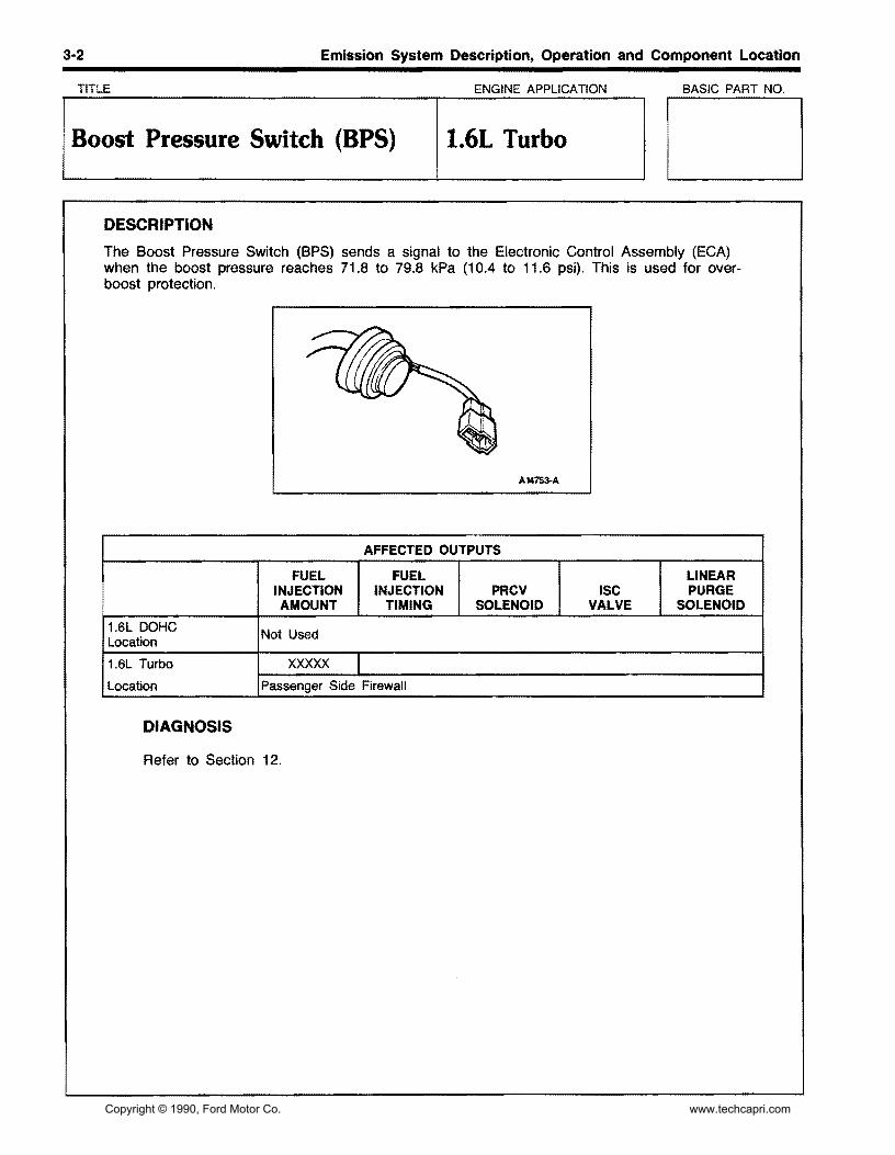
Boost Pressure Switch (BPS) 1.6L Turbo
DESCRIPTION
The Boost Pressure Switch (BPS) sends a signal to the Electronic Control Assembly (ECA) when the boost pressure reaches 71.8 to 79.8 kPa (10.4 to 11.6 psi). This is used for overboost protection.
3·4 Emission System Description, Operation and Component Location
TITLE ENGINE APPLICATION BASIC PART NO.
Canister Purge (CANP) Solenoid
All Engines
DESCRIPTION
The Canister Purge (CANP) Solenoid regulates the amount of evaporative vapors drawn from the Carbon Canister into the engine. The CANP Solenoid is controlled by the Electronic Control Assembly (ECA) and opens a passage between the Carbon Canister and the Intake Manifold.
3-5 Emission System Description, Operation and Component Location
TITLE ENGINE APPLICATION BASIC PART NO.
ICarbon Canister IAll Engines
DESCRIPTION
The Carbon Canister stores fuel vapors from the fuel tank until the vehicle is operated. During vehicle operation the Electronic Control Assembly (ECA) operates the CANP valve to purge the vapors from the canister.
3·6 Emission System Description, Operation and Component Location
TITLE ENGINE APPLICATION BASIC PART NO.
ICatalytic Converter IAll Engines
DESCRIPTION
The Catalytic Converter is a muffler-like component in the exhaust system that promotes a chemical reaction which converts certain air pollutants in the exhaust gases into harmless substances.
ENGINE LOCATION
1.6L DOHC Between the Exhaust Manifold and Muffler
1.6L Turbo Between the Exhaust Manifold and Muffler
3-8 Emission System Description, Operation and Component Location
TITLE ENGINE APPLICATION BASIC PART NO.
loashpot IAll Engines
DESCRIPTION
The Dashpot allows the Throttle Plate to gradually close during deceleration. This action prevents hesitation during the transition from deceleration to sudden acceleration and prevents engine stalling on sudden deceleration.
3-9 Emission System Description, Operation and Component Location
TITLE ENGINE APPLICATION BASIC PART NO.
Electronic Control Assembly (ECA)
All Engines
DESCRIPTION
The Electronic Control Assembly (ECA) receives signals from various inputs (VAT, VAF, EGO. TP, BP, and others). It takes the information received from the inputs and compares it with calibration information that is stored inside the ECA. The results of these comparisons produce changes on the states of ECA controlled devices (Fuel Injectors, !SC, CANP, and others). These changes are used to maintain proper Emission Levels, Fuel Economy and Driveability.
ENGINE LOCATION
1.6L DOHC Behind Center Console, Mounted to Firewall
1.6L Turbo Behind Center Console, Mounted to Firewall
3·10 Emission System Description, Operation and Component Location
TITLE ENGINE APPLICATION BASIC PART NO.
Engine Coolant Temperature (ECT) Sensor
All Engines
DESCRIPTION
The Engine Coolant Temperature (ECT) Sensor constantly supplies the Electronic Control Assembly (ECA) with a signal reflecting engine coolant temperature.
A14043-A
AFFECTED OUTPUTS
FUEL INJECTION AMOUNT
FUEL INJECTION
TIMING PRCV
SOLENOID ISC
VALVE
LINEAR PURGE
SOLENOID
1.6L DOHC
Location
xxxxx xxxxx xxxxx xxxxx Under-side of the Intake Manifold
1.6L Turbo
Location
xxxxx XXXXX XXXXX xxxxx Under-side of the Intake Manifold
3-11 Emission System Description, Operation and Component Location
TITLE ENGINE APPLICATION BASIC PART NO.
Exhaust Gas Oxygen (EGO) Sensor
All Engines
DESCRIPTION
The Exhaust Gas Oxygen (EGO) Sensor generates and supplies a signal to the Electronic Control Assembly (ECA) which reflects oxygen content in the exhaust system. The oxygen content in the exhaust gas reflects whether the fuel mixture is rich or lean. The ECA uses this information to regulate the air/fuel mixture.
3-12 Emission System Description, Operation and Component Location
TITLE ENGINE APPLICATION BASIC PART NO.
IFuel Filter IAll Engines
DESCRIPTION
The Fuel Filter is a high pressure paper element type that removes solid particles from the fuel that may clog the small orifices inside the fuel injectors.
FUEL FUEL FILTER INLET
A1461o-A
ENGINE LOCATION
1.6L DOHC Mounted Near the Center of the Firewall
1.6L Turbo Mounted Near the Center of the Firewall
3-13 Emission System Description, Operation and Component Location
TITLE ENGINE APPLICATION BASIC PART NO.
Fuel Injector All Engines
DESCRIPTION
The Fuel Injector is a solenoid operated valve that meters fuel flow into the engine. The amount of fuel that is injected into the engine is controlled by how long the Electronic Control Assembly (ECA) turns the injector on and the fuel pressure.
3-14 Emission System Description, Operation and Component Location
TITLE ENGINE APPLICATION BASIC PART NO.
Fuel Pressure Regulator All Engines
DESCRIPTION
The Fuel Pressure Regulator is attached to the Fuel Rail downstream from Fuel Injectors. The regulator uses a spring loaded diaphragm that is exposed to manifold vacuum to maintain constant fuel pressure across the injectors.
VACUUM SOURCE FROM PRESSURE REGULATOR CONTROL SOLENOID VALVE (EXCEPT 1.3L)
A14041-B
ENGINE LOCATION
1.6L DOHC Mounted on the Drivers Side of the Fuel Rail
1.6L Turbo Mounted on the Drivers Side of the Fuel Rail
3-17 Emission System Description, Operation and Component Location
TITLE ENGINE APPUCA TION BASIC PART NO.
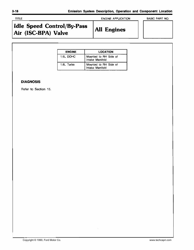
Idle Speed Control/By-Pass Air (ISC-BPA) Valve
All Engines
DESCRIPTION
The Idle Speed Control By·Pass Air (ISC·BPA) Valve controls idle speed by regulating air that by·passes the throttle plate.
There are two parts to the (ISC·BPA), The By·Pass Air Valve (BPA) and the Idle Speed Control Solenoid (lSC). The BPA Valve is thermally controlled and functions only during cold engine conditions (below 60°C [140°F]). The ISC Valve is controlled by the Electronic Control Assembly (ECA) and operates under all engine speed and temperature conditions.
The ISC·BPA valve controls:
• Cold Engine Fast Idle • Hot Engine Idle Speed
• No Touch Start • Engine Idle Load Corrections
TO INTAKE MANIFOLD
THERMO WAX
..
BYPASS AIR CHARACTERISTICS OF AIR VALVE AMOUNT LARGE
3-19 Emission System Description, Operation and Component Location
TITLE ENGINE APPLICATION BASIC PART NO.
IIdle Switch (lOLl IAll Engines
DESCRIPTION
The Idle Switch (IDL) sends an input to the Electronic Control Assembly (ECA) based on the throttle being at idle or off idle. The Idle Switch is integrated with the Throttle Position (TP) Sensor.
3·20 Emission System Description, Operation and Component Location
TITLE ENGINE APPLICATION BASIC PART NO.
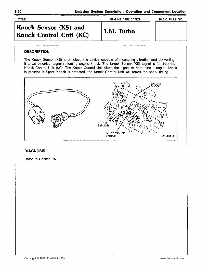
Knock Sensor (KS) and Knock Control Unit (KC)
1.6L Turbo
DESCRIPTION
The Knock Sensor (KS) is an electronic device capable of measuring vibration and converting it to an electrical signal reflecting engine knock. The Knock Sensor (KS) signal is fed into the Knock Control Unit (KC). The Knock Control Unit filters the signal to determine if engine knock is present. If Spark Knock is detected, the Knock Control Unit will retard the spark timing.
Emission System Description, Operation and Component Location 3·21
TITLE ENGINE APPLICATION BASIC PART NO.
Malfunction Indicator Light (MIL)
All Engines
DESCRIPTION
The Malfunction Indication Light (MIL) provides a visual warning to the driver in the event of an Engine Control failure. The MIL light also flashes codes during the Quick Test.
Emission System Description, Operation and Component Location 3·23
TITLE ENGINE APPLICATION BASIC PART NO.
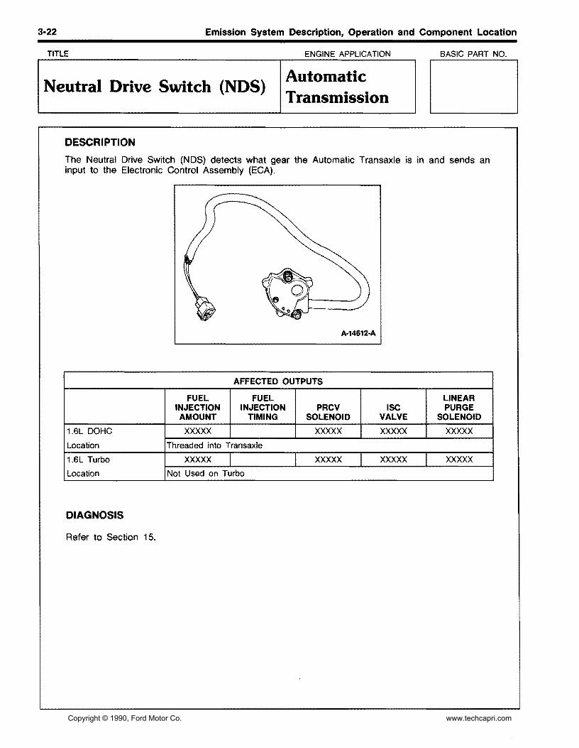
Neutral Gear Switch (NGS) Manual Transmission
DESCRIPTION
The Neutral Gear Switch (NGS) detects when the Manual Transaxle is in the In-Gear or Neutral position and sends an input to the Electronic Control Assembly (ECA).
3-24 Emission System Description, Operation and Component Location
TITLE ENGINE APPLICATION BASIC PART NO.
Positive Crankcase Ventilation (PCV) Valve
All Engines
DESCRIPTION
The Positive Crankcase Ventilation (PCV) Valve controls the amount of blow-by gas (vapors) pulled into the intake manifold from the crankcase. It also acts as a check valve by preventing the air from entering the crankcase in the opposite direction.
TO INTAKE PLENUM
INSERTED IN VALVE COVER
A-14614-A
ENGINE LOCATION
1.6L DOHC Connects to the Right Location Rear of the Valve Cover
1.6L Turbo Connects to the Right Location Rear of the Valve Cover
3-25 Emission System Description, Operation and Component Location
TITLE ENGINE APPLICATION BASIC PART NO.
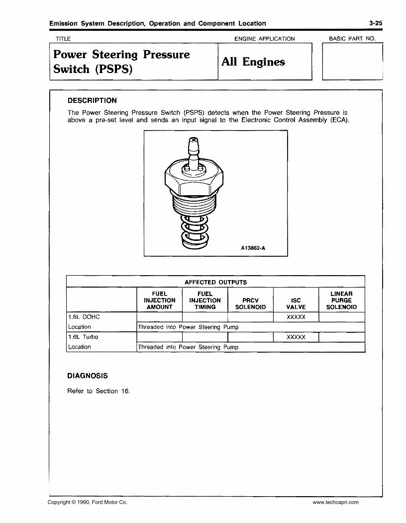
Power Steering Pressure Switch (PSPS)
All Engines
DESCRIPTION
The Power Steering Pressure Switch (PSPS) detects when the Power Steering Pressure is above a pre-set level and sends an input signal to the Electronic Control Assembly (ECA).
3-26 Emission System Description, Operation and Component Location
TITLE ENGINE APPLICATION BASIC PART NO.
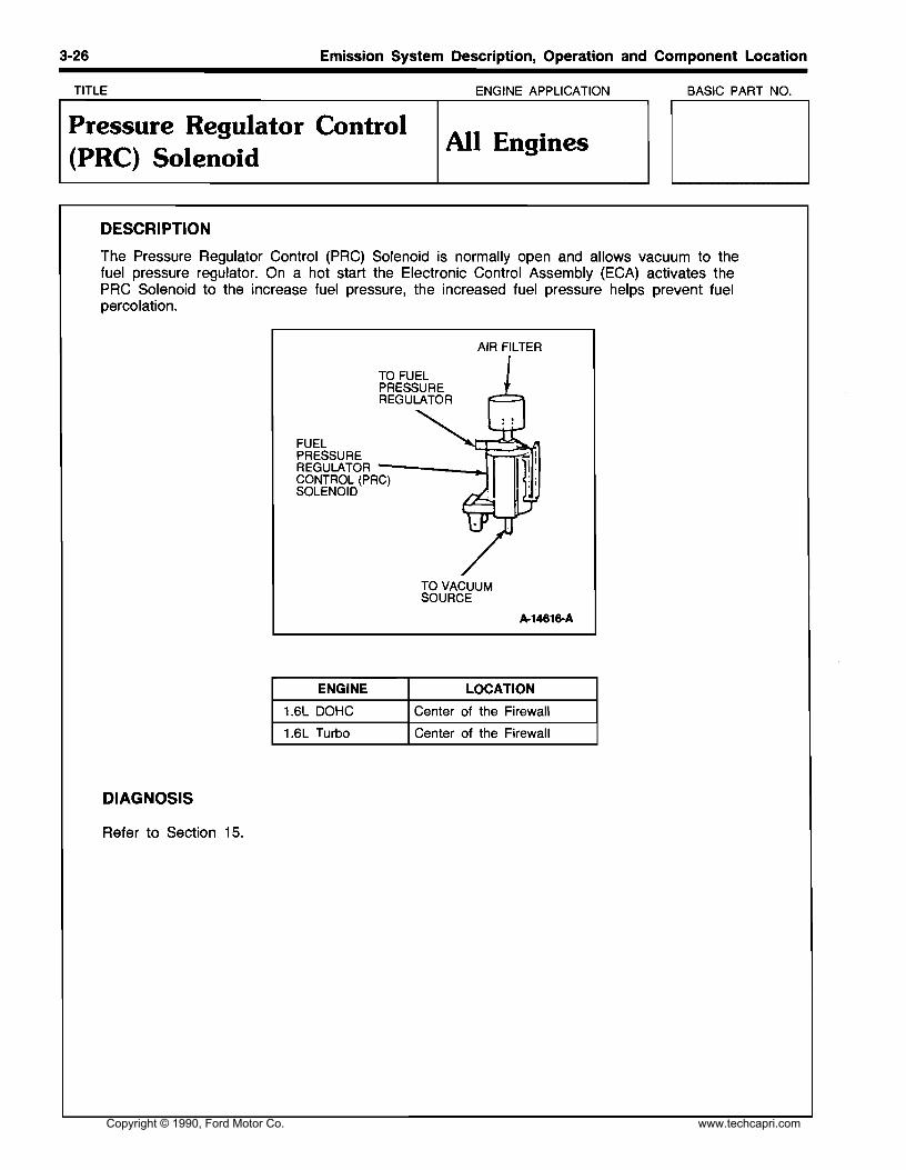
Pressure Regulator Control (PRC) Solenoid
All Engines
DESCRIPTION
The Pressure Regulator Control (PRC) Solenoid is normally open and allows vacuum to the fuel pressure regulator. On a hot start the Electronic Control Assembly (ECA) activates the PRC Solenoid to the increase fuel pressure, the increased fuel pressure helps prevent fuel percolation.
AIR FILTER
J
FUEL PRESSURE REGULATOR ----_..1 CONTROL (PRC) SOLENOID
3-27 Emission System Description, Operation and Component Location
TITLE ENGINE APPLICATION BASIC PART NO.
Self-Test Output/Self-Test Input (STO/STI)
All Engines
DESCRIPTION
The Self-Test Output (STO) and Self-Test Input (STI) connectors are used to perform engine control tests.
When the STI connector is jumped to ground, a signal is sent to the Electronic Control Assembly (ECA) activating the Self-Test mode. Information is sent from the ECA to the STO connector, this information can be read by using an Analog Voltmeter or a Super STAR II tester.
3-28 Emission System Description, Operation and Component Location
TITLE ENGINE APPLICATION BASIC PART NO.
Throttle Position Sensor (TP) All Engines
DESCRIPTION
The Throttle Position (TP) Sensor detects Throttle Plate opening angle and supplies the Electronic Control Assembly (ECA) with an input signal indicating throttle position.
3-29 Emission System Description, Operation and Component Location
TITLE ENGINE APPLICATION BASIC PART NO.
Vane Airflow (VAF) Meter All Engines
DESCRIPTION
The Vane Airflow (VAF) Meter measures air flow into the engine and is mounted between the Air Cleaner and The Throttle Body Assembly. The V AF Meter contains a movable vane which connects to a potentiometer. As air flows through the V AF Meter the Vane position is converted to a signal that is sent to the Electronic Control Assembly (ECA).
There are several components located inside the Vane Flow Meter Assembly. The Vane Air Temperature (VAT) Sensor and a Fuel Pump Switch which provides a ground for the Fuel Pump Circuit after the engine has started.
3·30 Emission System Description, Operation and Component Location
TITLE ENGINE APPLICATION BASIC PART NO.
Vane Air Temperature (VAT) Sensor
All Engines
DESCRIPTION
The Vane Air Temperature (VAT) Sensor is an integral part of the Vane Airflow Meter. The VAT Sensor measures the inlet air temperature and sends an input signal to the Electronic Control Assembly (ECA) based on the air temperature.