162
User Guide Rack Power Distribution Unit Metered-by-Outlet with Switching AP86XX 990-5570A-001 Publication Date: April, 2015
User GuideRack Power Distribution UnitMetered-by-Outlet with Switching
AP86XX
990-5570A-001
Publication Date: April, 2015

Schneider Electric IT Corporation Legal DisclaimerThe information presented in this manual is not warranted by the Schneider Electric IT Corporation to be authoritative, error free, or complete. This publication is not meant to be a substitute for a detailed operational and site specific development plan. Therefore, Schneider Electric IT Corporation assumes no liability for damages, violations of codes, improper installation, system failures, or any other problems that could arise based on the use of this Publication.
The information contained in this Publication is provided as is and has been prepared solely for the purpose of evaluating data center design and construction. This Publication has been compiled in good faith by Schneider Electric IT Corporation. However, no representation is made or warranty given, either express or implied, as to the completeness or accuracy of the information this Publication contains.
IN NO EVENT SHALL SCHNEIDER ELECTRIC IT CORPORATION, OR ANY PARENT, AFFILIATE OR SUBSIDIARY COMPANY OF SCHNEIDER ELECTRIC IT CORPORATION OR THEIR RESPECTIVE OFFICERS, DIRECTORS, OR EMPLOYEES BE LIABLE FOR ANY DIRECT, INDIRECT, CONSEQUENTIAL, PUNITIVE, SPECIAL, OR INCIDENTAL DAMAGES (INCLUDING, WITHOUT LIMITATION, DAMAGES FOR LOSS OF BUSINESS, CONTRACT, REVENUE, DATA, INFORMATION, OR BUSINESS INTERRUPTION) RESULTING FROM, ARISING OUT, OR IN CONNECTION WITH THE USE OF, OR INABILITY TO USE THIS PUBLICATION OR THE CONTENT, EVEN IF SCHNEIDER ELECTRIC IT CORPORATION HAS BEEN EXPRESSLY ADVISED OF THE POSSIBILITY OF SUCH DAMAGES. SCHNEIDER ELECTRIC IT CORPORATION RESERVES THE RIGHT TO MAKE CHANGES OR UPDATES WITH RESPECT TO OR IN THE CONTENT OF THE PUBLICATION OR THE FORMAT THEREOF AT ANY TIME WITHOUT NOTICE.
Copyright, intellectual, and all other proprietary rights in the content (including but not limited to software, audio, video, text, and photographs) rests with Schneider Electric It Corporation or its licensors. All rights in the content not expressly granted herein are reserved. No rights of any kind are licensed or assigned or shall otherwise pass to persons accessing this information.
This Publication shall not be for resale in whole or in part.
Contents
Introduction ..................................................................... 1Product Features. . . . . . . . . . . . . . . . . . . . . . . . . . . . . . . . . . . . . . . . . . 1
Types of User Accounts . . . . . . . . . . . . . . . . . . . . . . . . . . . . . . . . . . . . 2
Watchdog Features. . . . . . . . . . . . . . . . . . . . . . . . . . . . . . . . . . . . . . . . 3Overview . . . . . . . . . . . . . . . . . . . . . . . . . . . . . . . . . . . . . . . . . . . 3
Network interface watchdog mechanism . . . . . . . . . . . . . . . . . . 3
Resetting the network timer . . . . . . . . . . . . . . . . . . . . . . . . . . . . 3
Network Port Sharing (NPS). . . . . . . . . . . . . . . . . . . . . . . . . . . . . . . . . 4About the Network Port Sharing Feature . . . . . . . . . . . . . . . . . . 4
Display ID . . . . . . . . . . . . . . . . . . . . . . . . . . . . . . . . . . . . . . . . . . 4
Installation Instructions . . . . . . . . . . . . . . . . . . . . . . . . . . . . . . . . 4
Specific assignment of Display IDs . . . . . . . . . . . . . . . . . . . . . . . 4
Firmware Upgrade with NPS . . . . . . . . . . . . . . . . . . . . . . . . . . . . . . . . 5
RF Tag . . . . . . . . . . . . . . . . . . . . . . . . . . . . . . . . . . . . . . . . . . . . . . . . . . 5
EnergyWise . . . . . . . . . . . . . . . . . . . . . . . . . . . . . . . . . . . . . . . . . . . . . . 5
EnergyWise and NPS . . . . . . . . . . . . . . . . . . . . . . . . . . . . . . . . . . . . . . 6
Getting Started . . . . . . . . . . . . . . . . . . . . . . . . . . . . . . . . . . . . . . . . . . . 6
Establish Network Settings . . . . . . . . . . . . . . . . . . . . . . . . . . . . . . . . . 7IPv4 initial setup . . . . . . . . . . . . . . . . . . . . . . . . . . . . . . . . . . . . . 7
IPv6 initial setup . . . . . . . . . . . . . . . . . . . . . . . . . . . . . . . . . . . . . 7
TCP/IP configuration methods . . . . . . . . . . . . . . . . . . . . . . . . . . 7
.ini file utility . . . . . . . . . . . . . . . . . . . . . . . . . . . . . . . . . . . . . . . . 7
DHCP and BOOTP configuration . . . . . . . . . . . . . . . . . . . . . . . . 7
Network Management with Other Applications . . . . . . . . . . . . . . 8
Command Line Interface (CLI) . . . . . . . . . . . . . . . . . . . . . . . . . . 9
Recovering from a Lost Password . . . . . . . . . . . . . . . . . . . . . . . . . . 10
Rack PDU Front Panel ................................................. 11Network Status LED . . . . . . . . . . . . . . . . . . . . . . . . . . . . . . . . . 13
10/100 LED . . . . . . . . . . . . . . . . . . . . . . . . . . . . . . . . . . . . . . . . 13
Load indicator LED . . . . . . . . . . . . . . . . . . . . . . . . . . . . . . . . . . 13
Display Tree Example 1 . . . . . . . . . . . . . . . . . . . . . . . . . . . . . . 14
Display Tree Example 2 . . . . . . . . . . . . . . . . . . . . . . . . . . . . . . 15
Metered-by-Outlet with Switching Rack PDU i
Command Line Interface .............................................. 16About the Command Line Interface (CLI) . . . . . . . . . . . . . . . . . . . . . 16
Log on to the CLI. . . . . . . . . . . . . . . . . . . . . . . . . . . . . . . . . . . . . . . . . 16Remote access to the command line interface . . . . . . . . . . . . . 16
Telnet for basic access . . . . . . . . . . . . . . . . . . . . . . . . . . . . . . . 17
SSH for high-security access . . . . . . . . . . . . . . . . . . . . . . . . . . 17
Local access to the command line interface . . . . . . . . . . . . . . . 17
About the Main Screen . . . . . . . . . . . . . . . . . . . . . . . . . . . . . . . . . . . . 18
Using the CLI . . . . . . . . . . . . . . . . . . . . . . . . . . . . . . . . . . . . . . . . . . . . 19
Command Syntax . . . . . . . . . . . . . . . . . . . . . . . . . . . . . . . . . . . . . . . . 20
Command Response Codes . . . . . . . . . . . . . . . . . . . . . . . . . . . . . . . 20
Network Management Card Command Descriptions . . . . . . . . . . . 21? or help . . . . . . . . . . . . . . . . . . . . . . . . . . . . . . . . . . . . . . . . . . 21
about . . . . . . . . . . . . . . . . . . . . . . . . . . . . . . . . . . . . . . . . . . . . . 22
alarmcount . . . . . . . . . . . . . . . . . . . . . . . . . . . . . . . . . . . . . . . . 22
boot . . . . . . . . . . . . . . . . . . . . . . . . . . . . . . . . . . . . . . . . . . . . . . 23
bye . . . . . . . . . . . . . . . . . . . . . . . . . . . . . . . . . . . . . . . . . . . . . . 23
cd . . . . . . . . . . . . . . . . . . . . . . . . . . . . . . . . . . . . . . . . . . . . . . . 24
clrrst . . . . . . . . . . . . . . . . . . . . . . . . . . . . . . . . . . . . . . . . . . . . . 24
console . . . . . . . . . . . . . . . . . . . . . . . . . . . . . . . . . . . . . . . . . . . 25
date . . . . . . . . . . . . . . . . . . . . . . . . . . . . . . . . . . . . . . . . . . . . . . 26
delete . . . . . . . . . . . . . . . . . . . . . . . . . . . . . . . . . . . . . . . . . . . . 26
dir . . . . . . . . . . . . . . . . . . . . . . . . . . . . . . . . . . . . . . . . . . . . . . . 27
dns . . . . . . . . . . . . . . . . . . . . . . . . . . . . . . . . . . . . . . . . . . . . . . 27
email . . . . . . . . . . . . . . . . . . . . . . . . . . . . . . . . . . . . . . . . . . . . . 28
eventlog . . . . . . . . . . . . . . . . . . . . . . . . . . . . . . . . . . . . . . . . . . 29
exit or quit . . . . . . . . . . . . . . . . . . . . . . . . . . . . . . . . . . . . . . . . . 30
firewall . . . . . . . . . . . . . . . . . . . . . . . . . . . . . . . . . . . . . . . . . . . 30
format . . . . . . . . . . . . . . . . . . . . . . . . . . . . . . . . . . . . . . . . . . . . 30
ftp . . . . . . . . . . . . . . . . . . . . . . . . . . . . . . . . . . . . . . . . . . . . . . . 31
help . . . . . . . . . . . . . . . . . . . . . . . . . . . . . . . . . . . . . . . . . . . . . . 31
lang . . . . . . . . . . . . . . . . . . . . . . . . . . . . . . . . . . . . . . . . . . . . . . 31
lastrst . . . . . . . . . . . . . . . . . . . . . . . . . . . . . . . . . . . . . . . . . . . . 32
ledblink . . . . . . . . . . . . . . . . . . . . . . . . . . . . . . . . . . . . . . . . . . . 32
logzip . . . . . . . . . . . . . . . . . . . . . . . . . . . . . . . . . . . . . . . . . . . . 32
netstat . . . . . . . . . . . . . . . . . . . . . . . . . . . . . . . . . . . . . . . . . . . . 33
ntp . . . . . . . . . . . . . . . . . . . . . . . . . . . . . . . . . . . . . . . . . . . . . . . 33
ping . . . . . . . . . . . . . . . . . . . . . . . . . . . . . . . . . . . . . . . . . . . . . . 34
portSpeed . . . . . . . . . . . . . . . . . . . . . . . . . . . . . . . . . . . . . . . . . 35
Metered-by-Outlet with Switching Rack PDU ii
prompt . . . . . . . . . . . . . . . . . . . . . . . . . . . . . . . . . . . . . . . . . . . 35
pwd . . . . . . . . . . . . . . . . . . . . . . . . . . . . . . . . . . . . . . . . . . . . . . 36
radius . . . . . . . . . . . . . . . . . . . . . . . . . . . . . . . . . . . . . . . . . . . . 36
reboot . . . . . . . . . . . . . . . . . . . . . . . . . . . . . . . . . . . . . . . . . . . . 37
resetToDef . . . . . . . . . . . . . . . . . . . . . . . . . . . . . . . . . . . . . . . . 37
session . . . . . . . . . . . . . . . . . . . . . . . . . . . . . . . . . . . . . . . . . . . 38
smtp . . . . . . . . . . . . . . . . . . . . . . . . . . . . . . . . . . . . . . . . . . . . . 38
snmp . . . . . . . . . . . . . . . . . . . . . . . . . . . . . . . . . . . . . . . . . . . . . 39
snmpv3 . . . . . . . . . . . . . . . . . . . . . . . . . . . . . . . . . . . . . . . . . . . 40
snmptrap . . . . . . . . . . . . . . . . . . . . . . . . . . . . . . . . . . . . . . . . . . 40
system . . . . . . . . . . . . . . . . . . . . . . . . . . . . . . . . . . . . . . . . . . . 41
tcpip . . . . . . . . . . . . . . . . . . . . . . . . . . . . . . . . . . . . . . . . . . . . . 41
tcpip6 . . . . . . . . . . . . . . . . . . . . . . . . . . . . . . . . . . . . . . . . . . . . 42
user . . . . . . . . . . . . . . . . . . . . . . . . . . . . . . . . . . . . . . . . . . . . . . 43
userdflt . . . . . . . . . . . . . . . . . . . . . . . . . . . . . . . . . . . . . . . . . . . 44
web . . . . . . . . . . . . . . . . . . . . . . . . . . . . . . . . . . . . . . . . . . . . . . 45
whoami . . . . . . . . . . . . . . . . . . . . . . . . . . . . . . . . . . . . . . . . . . . 45
xferINI . . . . . . . . . . . . . . . . . . . . . . . . . . . . . . . . . . . . . . . . . . . . 46
xferStatus . . . . . . . . . . . . . . . . . . . . . . . . . . . . . . . . . . . . . . . . . 46
Device Command Descriptions . . . . . . . . . . . . . . . . . . . . . . . . . . . . . 47Network Port Sharing Commands . . . . . . . . . . . . . . . . . . . . . . 47
AssignUsr . . . . . . . . . . . . . . . . . . . . . . . . . . . . . . . . . . . . . . . . . 47
bkLowLoad . . . . . . . . . . . . . . . . . . . . . . . . . . . . . . . . . . . . . . . . 48
bkNearOver . . . . . . . . . . . . . . . . . . . . . . . . . . . . . . . . . . . . . . . 49
bkOverLoad . . . . . . . . . . . . . . . . . . . . . . . . . . . . . . . . . . . . . . . 49
bkReading . . . . . . . . . . . . . . . . . . . . . . . . . . . . . . . . . . . . . . . . 50
bkRestrictn . . . . . . . . . . . . . . . . . . . . . . . . . . . . . . . . . . . . . . . . 50
devLowLoad . . . . . . . . . . . . . . . . . . . . . . . . . . . . . . . . . . . . . . . 51
devNearOver . . . . . . . . . . . . . . . . . . . . . . . . . . . . . . . . . . . . . . 51
devOverLoad . . . . . . . . . . . . . . . . . . . . . . . . . . . . . . . . . . . . . . 51
devReading . . . . . . . . . . . . . . . . . . . . . . . . . . . . . . . . . . . . . . . 52
devStartDly . . . . . . . . . . . . . . . . . . . . . . . . . . . . . . . . . . . . . . . . 52
dispID . . . . . . . . . . . . . . . . . . . . . . . . . . . . . . . . . . . . . . . . . . . . 53
energyWise . . . . . . . . . . . . . . . . . . . . . . . . . . . . . . . . . . . . . . . . 53
humHyst . . . . . . . . . . . . . . . . . . . . . . . . . . . . . . . . . . . . . . . . . . 55
humLow . . . . . . . . . . . . . . . . . . . . . . . . . . . . . . . . . . . . . . . . . . 55
humMin . . . . . . . . . . . . . . . . . . . . . . . . . . . . . . . . . . . . . . . . . . . 56
humReading . . . . . . . . . . . . . . . . . . . . . . . . . . . . . . . . . . . . . . . 56
lcd . . . . . . . . . . . . . . . . . . . . . . . . . . . . . . . . . . . . . . . . . . . . . . . 56
lcdBlink . . . . . . . . . . . . . . . . . . . . . . . . . . . . . . . . . . . . . . . . . . . 57
olAssignUsr . . . . . . . . . . . . . . . . . . . . . . . . . . . . . . . . . . . . . . . 57
olCancelCmd . . . . . . . . . . . . . . . . . . . . . . . . . . . . . . . . . . . . . . 58
Metered-by-Outlet with Switching Rack PDU iii
i
olDlyOff . . . . . . . . . . . . . . . . . . . . . . . . . . . . . . . . . . . . . . . . . . . 58
olDlyOn . . . . . . . . . . . . . . . . . . . . . . . . . . . . . . . . . . . . . . . . . . . 59
olDlyReboot . . . . . . . . . . . . . . . . . . . . . . . . . . . . . . . . . . . . . . . 59
olGroups . . . . . . . . . . . . . . . . . . . . . . . . . . . . . . . . . . . . . . . . . . 60
olLowLoad . . . . . . . . . . . . . . . . . . . . . . . . . . . . . . . . . . . . . . . . 61
olName . . . . . . . . . . . . . . . . . . . . . . . . . . . . . . . . . . . . . . . . . . . 62
olNearOver . . . . . . . . . . . . . . . . . . . . . . . . . . . . . . . . . . . . . . . . 62
olOff . . . . . . . . . . . . . . . . . . . . . . . . . . . . . . . . . . . . . . . . . . . . . 63
olOffDelay . . . . . . . . . . . . . . . . . . . . . . . . . . . . . . . . . . . . . . . . . 63
olOn . . . . . . . . . . . . . . . . . . . . . . . . . . . . . . . . . . . . . . . . . . . . . 64
olOnDelay . . . . . . . . . . . . . . . . . . . . . . . . . . . . . . . . . . . . . . . . . 64
olOverLoad . . . . . . . . . . . . . . . . . . . . . . . . . . . . . . . . . . . . . . . . 65
olRbootTime . . . . . . . . . . . . . . . . . . . . . . . . . . . . . . . . . . . . . . . 66
olReading . . . . . . . . . . . . . . . . . . . . . . . . . . . . . . . . . . . . . . . . . 67
olReboot . . . . . . . . . . . . . . . . . . . . . . . . . . . . . . . . . . . . . . . . . . 67
olStatus . . . . . . . . . . . . . . . . . . . . . . . . . . . . . . . . . . . . . . . . . . . 68
olType . . . . . . . . . . . . . . . . . . . . . . . . . . . . . . . . . . . . . . . . . . . . 68
olUnasgnUsr . . . . . . . . . . . . . . . . . . . . . . . . . . . . . . . . . . . . . . . 69
phLowLoad . . . . . . . . . . . . . . . . . . . . . . . . . . . . . . . . . . . . . . . . 69
phNearOver . . . . . . . . . . . . . . . . . . . . . . . . . . . . . . . . . . . . . . . 70
phOverLoad . . . . . . . . . . . . . . . . . . . . . . . . . . . . . . . . . . . . . . . 70
phReading . . . . . . . . . . . . . . . . . . . . . . . . . . . . . . . . . . . . . . . . 71
phRestrictn . . . . . . . . . . . . . . . . . . . . . . . . . . . . . . . . . . . . . . . . 71
phTophVolts . . . . . . . . . . . . . . . . . . . . . . . . . . . . . . . . . . . . . . . 72
prodInfo . . . . . . . . . . . . . . . . . . . . . . . . . . . . . . . . . . . . . . . . . . 72
sensorName . . . . . . . . . . . . . . . . . . . . . . . . . . . . . . . . . . . . . . . 73
tempHigh . . . . . . . . . . . . . . . . . . . . . . . . . . . . . . . . . . . . . . . . . 74
tempHyst . . . . . . . . . . . . . . . . . . . . . . . . . . . . . . . . . . . . . . . . . 74
tempMax . . . . . . . . . . . . . . . . . . . . . . . . . . . . . . . . . . . . . . . . . . 75
tempReading . . . . . . . . . . . . . . . . . . . . . . . . . . . . . . . . . . . . . . 75
userAdd . . . . . . . . . . . . . . . . . . . . . . . . . . . . . . . . . . . . . . . . . . 76
userDelete . . . . . . . . . . . . . . . . . . . . . . . . . . . . . . . . . . . . . . . . 76
userList . . . . . . . . . . . . . . . . . . . . . . . . . . . . . . . . . . . . . . . . . . . 77
userPasswd . . . . . . . . . . . . . . . . . . . . . . . . . . . . . . . . . . . . . . . 78
Web Interface................................................................. 79Supported Web Browsers . . . . . . . . . . . . . . . . . . . . . . . . . . . . . . . . . 79
Log On to the Web Interface . . . . . . . . . . . . . . . . . . . . . . . . . . . . . . . 79Overview . . . . . . . . . . . . . . . . . . . . . . . . . . . . . . . . . . . . . . . . . . 79
URL address formats . . . . . . . . . . . . . . . . . . . . . . . . . . . . . . . . 79
Web Interface Features. . . . . . . . . . . . . . . . . . . . . . . . . . . . . . . . . . . . 80Tabs . . . . . . . . . . . . . . . . . . . . . . . . . . . . . . . . . . . . . . . . . . . . . 80
Device status icons . . . . . . . . . . . . . . . . . . . . . . . . . . . . . . . . . . 81
Quick Links . . . . . . . . . . . . . . . . . . . . . . . . . . . . . . . . . . . . . . . . 81
Metered-by-Outlet with Switching Rack PDUv
Network Port Sharing (NPS) on the Web User Interface (UI) . . . . . 82Group Control using Network Port Sharing . . . . . . . . . . . . . . . 82
About Home. . . . . . . . . . . . . . . . . . . . . . . . . . . . . . . . . . . . . . . . . . . . . 83The Overview view . . . . . . . . . . . . . . . . . . . . . . . . . . . . . . . . . . 83
Status Tab...................................................................... 84About the Status Tab . . . . . . . . . . . . . . . . . . . . . . . . . . . . . . . . . . . . . 84
View the Load Status and Peak Load . . . . . . . . . . . . . . . . . . . 85
View the Network Status . . . . . . . . . . . . . . . . . . . . . . . . . . . . . 85
Current IPv4 Settings . . . . . . . . . . . . . . . . . . . . . . . . . . . . . . . . 85
Current IPv6 Settings . . . . . . . . . . . . . . . . . . . . . . . . . . . . . . . . 85
Domain Name System Status . . . . . . . . . . . . . . . . . . . . . . . . . 86
Ethernet Port Speed . . . . . . . . . . . . . . . . . . . . . . . . . . . . . . . . . 86
Control ........................................................................... 87Controlling RPDU Outlets . . . . . . . . . . . . . . . . . . . . . . . . . . . . . . . . . 88
To control the outlets on your Rack PDU . . . . . . . . . . . . . . . . . 88
Control actions you can select . . . . . . . . . . . . . . . . . . . . . . . . . 88
Managing User Sessions . . . . . . . . . . . . . . . . . . . . . . . . . . . . . . . . . . 89
Resetting the Network Interface . . . . . . . . . . . . . . . . . . . . . . . . . . . . 89
Configuration................................................................. 90About the Configuration Tab . . . . . . . . . . . . . . . . . . . . . . . . . . . . . . . 90
Configure Load Thresholds . . . . . . . . . . . . . . . . . . . . . . . . . . . . . . . . 91To configure load thresholds . . . . . . . . . . . . . . . . . . . . . . . . . . 91
Configure RPDU Name and Location . . . . . . . . . . . . . . . . . . . . . . . . 91
Set the Coldstart Delay for the Rack PDU . . . . . . . . . . . . . . . . . . . . 91
Reset Peak Load and kWh . . . . . . . . . . . . . . . . . . . . . . . . . . . . . . . . . 91
Set the Overload Outlet Restrictions . . . . . . . . . . . . . . . . . . . . . . . . 92To set Overload Outlet Restrictions: . . . . . . . . . . . . . . . . . . . . . 92
Configure and Control Outlet Groups. . . . . . . . . . . . . . . . . . . . . . . . 92Outlet group terminology . . . . . . . . . . . . . . . . . . . . . . . . . . . . . 92
Purpose and benefits of outlet groups . . . . . . . . . . . . . . . . . . . 92
System requirements for outlet groups . . . . . . . . . . . . . . . . . . . 93
Rules for configuring outlet groups . . . . . . . . . . . . . . . . . . . . . . 93
Enable outlet groups . . . . . . . . . . . . . . . . . . . . . . . . . . . . . . . . . 94
Create a local outlet group . . . . . . . . . . . . . . . . . . . . . . . . . . . . 94
Create a global outlet group . . . . . . . . . . . . . . . . . . . . . . . . . . . 95
Metered-by-Outlet with Switching Rack PDU v
v
Edit or delete an outlet group . . . . . . . . . . . . . . . . . . . . . . . . . . 95
Typical outlet group configurations . . . . . . . . . . . . . . . . . . . . . . 96
Verify your setup and configuration for global outlet groups . . . 97
Outlet Settings. . . . . . . . . . . . . . . . . . . . . . . . . . . . . . . . . . . . . . . . . . . 97Configure outlet settings and the outlet name . . . . . . . . . . . . . 97
Schedule Outlet Actions. . . . . . . . . . . . . . . . . . . . . . . . . . . . . . . . . . . 98Actions you can schedule . . . . . . . . . . . . . . . . . . . . . . . . . . . . . 98
Schedule an outlet event . . . . . . . . . . . . . . . . . . . . . . . . . . . . . 99
Edit, disable, enable, or delete a scheduled outlet event . . . . . 99
Outlet User Manager . . . . . . . . . . . . . . . . . . . . . . . . . . . . . . . . . . . . . 100Configure an outlet user . . . . . . . . . . . . . . . . . . . . . . . . . . . . . 100
Outlet Manager and Network Port Sharing . . . . . . . . . . . . . . . 100
Configure Temperature and Humidity Sensors . . . . . . . . . . . . . . . 101
Security . . . . . . . . . . . . . . . . . . . . . . . . . . . . . . . . . . . . . . . . . . . . . . . 102Session Management screen . . . . . . . . . . . . . . . . . . . . . . . . . 102
Ping Response . . . . . . . . . . . . . . . . . . . . . . . . . . . . . . . . . . . . 102
Local Users . . . . . . . . . . . . . . . . . . . . . . . . . . . . . . . . . . . . . . . 102
Remote Users . . . . . . . . . . . . . . . . . . . . . . . . . . . . . . . . . . . . . 104
Configure the RADIUS Server . . . . . . . . . . . . . . . . . . . . . . . . 105
Supported RADIUS servers . . . . . . . . . . . . . . . . . . . . . . . . . . 105
RADIUS and Network Port Sharing . . . . . . . . . . . . . . . . . . . . 105
Firewall Menus . . . . . . . . . . . . . . . . . . . . . . . . . . . . . . . . . . . . 106
Network Features . . . . . . . . . . . . . . . . . . . . . . . . . . . . . . . . . . . . . . . 107TCP/IP and Communication Settings . . . . . . . . . . . . . . . . . . . 107
Port Speed . . . . . . . . . . . . . . . . . . . . . . . . . . . . . . . . . . . . . . . 109
DNS . . . . . . . . . . . . . . . . . . . . . . . . . . . . . . . . . . . . . . . . . . . . 110
Web . . . . . . . . . . . . . . . . . . . . . . . . . . . . . . . . . . . . . . . . . . . . 111
Console . . . . . . . . . . . . . . . . . . . . . . . . . . . . . . . . . . . . . . . . . 112
SNMP . . . . . . . . . . . . . . . . . . . . . . . . . . . . . . . . . . . . . . . . . . . 114
SNMPv1 . . . . . . . . . . . . . . . . . . . . . . . . . . . . . . . . . . . . . . . . . 115
SNMPv3 . . . . . . . . . . . . . . . . . . . . . . . . . . . . . . . . . . . . . . . . . 116
FTP Server . . . . . . . . . . . . . . . . . . . . . . . . . . . . . . . . . . . . . . . 117
Notifications . . . . . . . . . . . . . . . . . . . . . . . . . . . . . . . . . . . . . . . . . . . 118Event Actions . . . . . . . . . . . . . . . . . . . . . . . . . . . . . . . . . . . . . 118
Configure event actions . . . . . . . . . . . . . . . . . . . . . . . . . . . . . 118
E-mail notification screens . . . . . . . . . . . . . . . . . . . . . . . . . . . 120
SNMP trap receiver screen . . . . . . . . . . . . . . . . . . . . . . . . . . 122
SNMP traps test screen . . . . . . . . . . . . . . . . . . . . . . . . . . . . . 123
Remote Monitoring Service . . . . . . . . . . . . . . . . . . . . . . . . . . 123
Metered-by-Outlet with Switching Rack PDUi
General Menu . . . . . . . . . . . . . . . . . . . . . . . . . . . . . . . . . . . . . . . . . . 124Identification screen . . . . . . . . . . . . . . . . . . . . . . . . . . . . . . . . 124
Date/Time screen . . . . . . . . . . . . . . . . . . . . . . . . . . . . . . . . . . 124
Creating and importing settings with the config file . . . . . . . . 126
Configure Links . . . . . . . . . . . . . . . . . . . . . . . . . . . . . . . . . . . . 126
Logs in the Configuration Menu . . . . . . . . . . . . . . . . . . . . . . . . . . . 127Identifying Syslog servers . . . . . . . . . . . . . . . . . . . . . . . . . . . . 127
Syslog settings . . . . . . . . . . . . . . . . . . . . . . . . . . . . . . . . . . . . 127
Syslog test and format example . . . . . . . . . . . . . . . . . . . . . . . 128
Tests Tab ..................................................................... 129Setting the RPDU LCD or LED Lights to Blink . . . . . . . . . . . . . . . . 129
Logs Tab ...................................................................... 130Event, Data and Firewall Logs . . . . . . . . . . . . . . . . . . . . . . . . . . . . . 130
Event log . . . . . . . . . . . . . . . . . . . . . . . . . . . . . . . . . . . . . . . . . 130
Data log . . . . . . . . . . . . . . . . . . . . . . . . . . . . . . . . . . . . . . . . . 132
Firewall Logs . . . . . . . . . . . . . . . . . . . . . . . . . . . . . . . . . . . . . 134
Use FTP or SCP to retrieve log files . . . . . . . . . . . . . . . . . . . . 134
About Tab .................................................................... 136About the Rack PDU . . . . . . . . . . . . . . . . . . . . . . . . . . . . . . . . . . . . . 136
Device IP Configuration Wizard................................. 137Capabilities, Requirements, and Installation . . . . . . . . . . . . . . . . . 137
How to use the Wizard to configure TCP/IP settings . . . . . . . 137
System requirements . . . . . . . . . . . . . . . . . . . . . . . . . . . . . . . 137
Installation . . . . . . . . . . . . . . . . . . . . . . . . . . . . . . . . . . . . . . . 137
How to Export Configuration Settings...................... 138Retrieving and Exporting the .ini File . . . . . . . . . . . . . . . . . . . . . . . 138
Summary of the procedure . . . . . . . . . . . . . . . . . . . . . . . . . . . 138
Contents of the .ini file . . . . . . . . . . . . . . . . . . . . . . . . . . . . . . 138
.ini and Network Port Sharing . . . . . . . . . . . . . . . . . . . . . . . . . 138
Detailed procedures . . . . . . . . . . . . . . . . . . . . . . . . . . . . . . . . 139
The Upload Event and Error Messages . . . . . . . . . . . . . . . . . . . . . 140The event and its error messages . . . . . . . . . . . . . . . . . . . . . 140
Messages in config.ini . . . . . . . . . . . . . . . . . . . . . . . . . . . . . . 141
Errors generated by overridden values . . . . . . . . . . . . . . . . . 141
Related Topics. . . . . . . . . . . . . . . . . . . . . . . . . . . . . . . . . . . . . . . . . . 141
Metered-by-Outlet with Switching Rack PDU vii
File Transfers ............................................................... 142Upgrading Firmware. . . . . . . . . . . . . . . . . . . . . . . . . . . . . . . . . . . . . 142
Benefits of upgrading firmware . . . . . . . . . . . . . . . . . . . . . . . .142
Firmware module files (Rack PDU) . . . . . . . . . . . . . . . . . . . . .142
Firmware File Transfer Methods . . . . . . . . . . . . . . . . . . . . . . . . . . . 143Using the Firmware Upgrade Utility . . . . . . . . . . . . . . . . . . . .143
Use FTP or SCP to upgrade one Rack PDU . . . . . . . . . . . . .144
Use XMODEM to upgrade one Rack PDU . . . . . . . . . . . . . . .145
Use a USB drive to transfer and upgrade the files . . . . . . . . .145
How to upgrade multiple RPDUs . . . . . . . . . . . . . . . . . . . . . .146
Using the Firmware Upgrade Utility for multiple upgrades . . .146
Updating firmware for Network Port Sharing (NPS) Groups . .146
Verifying Upgrades and Updates . . . . . . . . . . . . . . . . . . . . . . . . . . 147Verify the success or failure of the transfer . . . . . . . . . . . . . . .147
Last Transfer Result codes . . . . . . . . . . . . . . . . . . . . . . . . . . .147
Verify the version numbers of installed firmware. . . . . . . . . . .147
Troubleshooting .......................................................... 148Rack PDU Access Problems . . . . . . . . . . . . . . . . . . . . . . . . . . . . . . 148
SNMP Issues . . . . . . . . . . . . . . . . . . . . . . . . . . . . . . . . . . . . . . . . . . . 150
Metered-by-Outlet with Switching Rack PDUviii
Introduction
Product FeaturesThe Schneider Electric Metered-by-Outlet with Switching Rack Power Distribution Unit (PDU) may be used as a stand-alone, network-manageable power distribution device or up to four devices can be connected together using one network connection. The Rack PDU provides real-time remote monitoring of connected loads. User-defined alarms warn of potential circuit overloads. The Rack PDU provides full control over outlets through remote commands and user interface settings.
Your Rack PDU comes with a terminator installed in the display In or Out port. In stand-alone operation of AP86XX Metered-by-Outlet with Switching models, one terminator must be installed in the display In or Out port. To use Network Port Sharing between up to four units, a terminator must be installed in the In port at one end of the group and another on the Out port at the other end of the group.
You can manage a Rack PDU through its web interface (UI), its command line interface (CLI), StruxureWare, or Simple Network Management Protocol (SNMP). (To use the PowerNet MIB with an SNMP browser, see the PowerNet SNMP Management Information Base (MIB) Reference Guide, available at www.schneider-electric.com.) Rack PDUs have these additional features:
• Device power, peak power, apparent power, power factor and energy.
• Phase voltage, current, peak current, power, apparent power and power factor.
• Bank current and peak current (for models that support breaker banks).
• Outlet current, energy, and power monitoring.
• Configurable alarm thresholds that provide network and visual alarms to help avoid overloaded circuits.
• Various levels of access: Super User, Administrator, Device User, Read-Only, Outlet User, and Network-Only User (These are protected by user name and password requirements).
• Multiple user login feature which allows up to four users to be logged in simultaneously.
• Individual outlet control.
• Configurable power delays.
• Event and data logging. The event log is accessible by Telnet, Secure CoPy (SCP), File Transfer Protocol (FTP), serial connection, or web browser (using HTTPS access with SSL, or using HTTP access). The data log is accessible by web browser, SCP, or FTP.
• E-mail notifications for Rack PDU and Network Management Card (NMC) system events.
• SNMP traps, Syslog messages, and e-mail notifications based on the severity level or category of the Rack PDU and NMC system event.
• Security protocols for authentication and encryption.
• Network Port Sharing (NPS). Up to four Rack PDUs of any model can be connected using the In and Out ports so that only one network connection is necessary.
• NPS guest firmware auto-update feature allows the NPS host to automatically pass a firmware update to its connected guests. This feature will be functional for all guests that have AOS firmware version 6.1.3 or later.
• RF Code wireless monitoring support via serial port connection
• Cisco EnergyWise certified.
Note: The Rack PDU does not provide power surge protection. To ensure that the device is protected from power failure or power surges, connect the Rack PDU to a Schneider Electric Uninterruptible Power Supply (UPS).
1Metered-by-Outlet with Switching Rack PDU
Types of User AccountsThe Rack PDU has various levels of access (Super User, Administrator, Device User, Read-Only User, Outlet User, and Network-Only User), which are protected by user name and password requirements. Up to four users are allowed to login to the same Rack PDU simultaneously (available in AOS version 6.1.3 or later).
• An Administrator or the Super User can use all of the menus in the UI and all of the commands in the CLI. Administrator user types can be deleted, but the Super User cannot be deleted. The default user name and password for the Super User are both apc.
– The Super User or Administrator can manage another Administrator's account (enable, disable, change password, etc).
• A Device User has read and write access to device-related screens. Administrative functions like session management under the Security menu and Firewall under Logs are grayed out.
• A Read-Only User has the following restricted access:
– Access to the same menus as a Device User, but without the capability to change configurations, control devices, delete data, or use file transfer options. Links to configuration options are visible but disabled. The event and data logs display no button to clear the log.
• An Outlet User has the following restricted access:
– Access through the web interface and command line interface.
– Access to the same menus as a Device User, but with limited capability to change configurations, control devices, delete data, or use file transfer options. Links to configuration options are visible but are disabled. The Outlet User has access to the Outlet Control menu option that allows the user to control only the outlets assigned by the Administrator. Outlet Users cannot clear the event or data logs. The user name and password are defined by the Administrator during the process of adding a new Outlet User.
• A Network-Only User can only log on using the Web UI and CLI (telnet, not serial). A network-only user has read/right access to the network related menus only.
Metered-by-Outlet with Switching Rack PDU2
Watchdog FeaturesOverviewTo detect internal problems and recover from unanticipated inputs, the Rack PDU uses internal, system-wide watchdog mechanisms. When it restarts to recover from an internal problem, a Network Interface Restarted event is recorded in the event log.
Network interface watchdog mechanismThe Rack PDU implements internal watchdog mechanisms to protect itself from becoming inaccessible over the network. For example, if the Rack PDU does not receive any network traffic for 9.5 minutes (either direct traffic, such as SNMP, or broadcast traffic, such as an Address Resolution Protocol [ARP] request), it assumes that there is a problem with its network interface and restarts. The network interface watchdog mechanism is only enabled on a PDU that discovers and active network interface connection at start-up. This allows guest PDUs in a Network Port Sharing chain to function normally without rebooting every 9.5 minutes.
Resetting the network timerTo ensure that the Rack PDU does not restart if the network is quiet for 9.5 minutes, the Rack PDU attempts to contact the default gateway every 4.5 minutes. If the gateway is present, it responds to the Rack PDU, and the response restarts the 9.5-minute timer. If your application does not require or have a gateway, specify the IP address of a computer that is running on the network and is on the same subnet. The network traffic of that computer will restart the 9.5-minute time frequently enough to prevent the Rack PDU from restarting.
3Metered-by-Outlet with Switching Rack PDU
Network Port Sharing (NPS)About the Network Port Sharing FeatureYou can use the Network Port Sharing feature to view the status of and configure and manage up to four Rack PDUs using only one network connection. This is made possible by connecting the Rack PDUs via the In and Out ports on the Rack PDU front panel.
Note: All Rack PDUs in the group must be using the same Rack PDU firmware revision, 5.1.5 or later (excluding v6.0.5 EnergyWise), in order to support the Network Port Sharing Feature.
Display IDThe display ID is a number, 1 to 4, used to uniquely identify the Rack PDUs in a group. After two or more Rack PDUs are connected to one another in an NPS group, they can be identified on the various interfaces by the use of this "Display ID". This Display ID is viewable in the top left corner of the display. Alternatively, a larger Display ID “shadow” can be enabled on the LCD by selecting the Display Settings > Display ID > Show option on the LCD keypad.
Installation InstructionsConnect up to four Rack PDUs via the In and Out ports on the Rack PDU. Insert an RJ45 terminator (included) in the unused In/Out ports on each end of the chain.
Note: Failure to use terminators may cause a loss of communication on the Rack PDUs.
Note: To reduce the possibility of communication issues, the maximum total length of cabling connecting Rack PDUs in a group should not exceed 10 meters. All Rack PDUs in a NPS group should reside in the same rack enclosure.
Connect the "Network" port of one of the grouped Rack PDUs to a network hub or switch. This unit will be the Host for the Rack PDU group. Guest PDU data will be viewable on the Host PDU. Set up network functionality for this Host Rack PDU as specified in the Establish Network Settings section. The Host will automatically discover any Guest PDUs connected via In/Out ports. The Rack PDU group is now available via the Host's IP address.
Note: Only one Rack PDU in an NPS group is allowed to be the host. If two host Rack PDUs are connected together, one will automatically be chosen to be the single host for the NPS group. The user also has the option to select a particular guest to be the host as long as that guest has an active network link.
The host Rack PDU supports many features that are not supported by NPS guests. These include, but are not limited to:
• SNMP rPDU2Group OIDs• EnergyWise support• Initiating AOS/App firmware updates for guest Rack PDUs• Time synchronization for guest Rack PDUs• Data logging for the guest Rack PDUs
Specific assignment of Display IDsFollow the instructions below before powering up any of the Rack PDUs in the group.
If it is desired to have a specific assignment of Display IDs, this can be achieved by powering up the units for the first time in the desired order, 1 to 4. For example, before powering up any of the Rack PDUs connected in a group, determine the Display ID order that you would like. Then, first power up the unit that you would like to have Display ID 1. After that unit has initialized and the LCD has started displaying its screens, power on the unit that you would like to have Display ID 2. Continue in the same way for units 3 and 4, if applicable for your setup.
Note: The Display ID can be configured from the web interface via the "Configuration > RPDU > Device > Display ID" field. The Display ID can also be configured from the CLI interface via the dispID command.
Metered-by-Outlet with Switching Rack PDU4
Firmware Upgrade with NPSAt start-up and routinely during operation, the rPDU2g NPS host compares its own AOS and application versions with the versions found on each guest. In the event of a version difference, the host copies its AOS and then its application to the non-complying guests via the NPS chain.
Note: Automatic firmware upgrade is only available for Rack PDUs running AOS version v6.1.3 or later as this functionality requires resident firmware support in the NPS host and guests. This functionality requires that any replacement Rack PDUs also be running AOS version v6.1.3 or later to maintain correct operation of the NPS chain.
RF TagThe Rack PDU supports the RF Code sensor tag for Schneider Electric Rack PDUs. The tag enables data center managers to wirelessly monitor power consumption and utilization with the enterprise-class Asset RF Code Zone Manager. The Zone Manager middleware consumes information about power attribute values as reported by the Rack PDU. The RF Code sensor tag for Schneider Electric works in concert with the AP8XXX Rack PDUs with firmware v6.0.9 or later. To implement an RF Code sensor tag solution, plug the tag into the RJ-12 socket labeled Serial Port. Scroll the LCD menu to highlight the RF Code Control entry, press the Select button. Press the select button again to enable. The Rack PDU will immediately reboot and start serial communication with the tag. When an NPS guest RF tag is removed, the NPS host will signal an alarm. In order to clear this alarm, one must replace the tag and disable the tag in the LCD menu. Then the error will be cleared and the NPS guest will auto reboot.
The RF Tag reports per-phase load voltage/amperage/power readings every 10 minutes and device power/energy use, per-outlet watt-hour/switch state/RMS current, and phase outlet voltages/bank overload state readings every hour. Outlet and bank readings are Rack PDU model dependent as all models do not support monitoring. The complete RF solution requires an RF Code reader, an RF Code Zone Manager, or RF Code Asset Manager. For more information see: www.rfcode.com.
EnergyWiseThe Rack PDU has the capability of becoming a Cisco EnergyWise Entity. This entity reports power usage and alarms in the EnergyWise Domain.
To exercise this capability, plug the Rack PDU network port into a Cisco switch/router that supports the EnergyWise Domain. Log into the web interface of the Rack PDU and navigate to the Configuration/RPDU/EnergyWise web page. Click on the enable radio button to initiate the task. The task will generate unique parent and children names, default roles, keywords and importance values that comply with EnergyWise requirements. Customization of the aforementioned is supported by clicking on any of the underlined entities to navigate to a configuration web page.
The EnergyWise port, domain name and shared secret may also be modified, but must be coordinated with the same parameters in the Cisco gear.
The Rack PDU implementation supports a single parent, multiple children hierarchy. The parent may exist as a standalone Rack PDU or as the host Rack PDU for an NPS chain of Rack PDUs. The parent usage reports the power consumed by the Rack PDUs themselves, including any NPS guest Rack PDUs. The children report either inlet power or, in the case of monitored outlets, the power consumed at the outlet. Both parent and children report a usage level (0-10 scale). The parent and inlet usage are always reported as 10 or “On”. In the case of switched outlets the actual state of the switch is reported and may also be altered by the Cisco device.
When the parent is the host Rack PDU of an NPS chain, the reported parent power is the sum of the parent and each of the NPS guests. The parent also reports an inlet entity for itself and for each guest as well as an outlet entity for each host outlet and each outlet of every guest.
The remaining configurable items are string variables that may be modified as needed and are retained across power cycles or reboots.
5Metered-by-Outlet with Switching Rack PDU
EnergyWise and NPSAP8XXX RPDUs support Cisco EnergyWise with Rack PDU v6.0.9 firmware or later. The Rack PDU EnergyWise application generates a family tree at startup. This tree is reported to Cisco hardware during the discovery process.
For an initial installation, either establish the NPS chain and enable EnergyWise on the host or enable EnergyWise on the host and then disable and re-enable EnergyWise after the NPS communication is established. Clearly, the first option is simpler.
For Rack PDU replacement, the following procedure should be followed. Power down the PDU – any children associated with this PDU will report EW levels and usage as zero. On the Status/Rack PDU/Group web page, there should be a check box to allow the user to remove the now non-functioning PDU from the NPS chain. Once removed from the chain, any children associated with that PDU will report “.0.” in the display identifier portion of the EW name field. At this time, one can replace the PDU with another of the same model and expect the EnergyWise to function properly again once communication is established. If for some reason the replacement model is different, EnergyWise will have to be disabled and re-enabled after NPS communication is established, to update the family tree and the order of data reported. For more information see: www.cisco.com/en/us/products/ps10195/index.html.
Getting StartedTo start using the Rack PDU:
1. Install the Rack PDU using the Rack Power Distribution Unit Installation Instructions that were shipped with your Rack PDU.
2. Apply power and connect to your network. Follow the directions in the Rack Power Distribution Unit Installation Instructions.
3. Establish network settings
4. Begin using the Rack PDU by way of one of the following:
– “Web Interface” on page 79
– “Command Line Interface” on page 16
– “Rack PDU Front Panel” on page 11
Metered-by-Outlet with Switching Rack PDU6
Establish Network SettingsIPv4 initial setupYou must define three TCP/IP settings for the Rack PDU before it can operate on the network:
• The IP address of the Rack PDU
• The subnet mask of the Rack PDU
• The IP address of the default gateway (only needed if you are going off segment)
Note: Do NOT use the loopback address (127.0.0.1) as the default gateway. Doing so disables the card. To enable again, you must log on using a serial connection and reset the TCP/IP settings to their defaults.
For detailed information on how to use a DHCP server to configure the TCP/IP settings at an Rack PDU, see.“DHCP response options” on page 108
IPv6 initial setupIPv6 network configuration provides flexibility to accommodate your requirements. IPv6 can be used anywhere an IP address is entered on this interface. You can configure manually, automatically, or using DHCP.
TCP/IP configuration methodsUse one of the following methods to define the TCP/IP settings needed by the Rack PDU:
• “Device IP Configuration Wizard” on page 137
• “DHCP and BOOTP configuration”
• “Command Line Interface” on page 16
.ini file utilityYou can use the .ini file export utility to export .ini file settings from configured Rack PDUs to one or more unconfigured Rack PDUs. For more information, see “Creating and importing settings with the config file” on page 126.
DHCP and BOOTP configurationThe default TCP/IP configuration setting, DHCP, assumes that a properly configured DHCP server is available to provide TCP/IP settings to Rack PDU. You can also configure the setting for BOOTP.
A user configuration (INI) file can function as a BOOTP or DHCP boot file. For more information, see “Creating and importing settings with the config file” on page 126.
If neither of these servers is available, see “Device IP Configuration Wizard” on page 137 or “Device IP Configuration Wizard” on page 137.
BOOTPFor the Rack PDU to use a BOOTP server to configure its TCP/IP settings, it must find a properly configured RFC951-compliant BOOTP server.
In the BOOTPTAB file of the BOOTP server, enter the Rack PDU’s MAC address, IP address, subnet mask, and default gateway, and, optionally, a bootup file name. Look for the MAC address on the bottom of the Rack PDU or on the Quality Assurance slip included in the package.
When the Rack PDU reboots, the BOOTP server provides it with the TCP/IP settings.
• If you specified a bootup file name, the Rack PDU attempts to transfer that file from the BOOTP server using TFTP or FTP. The Rack PDU assumes all settings specified in the bootup file.
• If you did not specify a bootup file name, you can configure the other settings of the Rack PDU remotely through its “Web Interface” on page 79 or “Command Line Interface” on page 16; the user name and password are both apc, by default. To create a bootup file, see your BOOTP server documentation.
7Metered-by-Outlet with Switching Rack PDU
DHCP You can use an RFC2131/RFC2132-compliant DHCP server to configure the TCP/IP settings for the Rack PDU.
This section summarizes the Rack PDU’s communication with a DHCP server. For more detail about how a DHCP server can configure the network settings for a Rack PDU, see “DHCP response options” on page 108.
1. The Rack PDU sends out a DHCP request that uses the following to identify itself:
– A Vendor Class Identifier (APC by default)
– A Client Identifier (by default, the MAC address of the Rack PDU)
– A User Class Identifier (by default, the identification of the application firmware installed on the Rack PDU)
– A Host Name (by default, apcXXYYZZ with XXYYZZ being the last six digits of the PDU). This is known as DHCP Option 12.
2. A properly configured DHCP server responds with a DHCP offer that includes all the settings that the Rack PDU needs for network communication. The DHCP offer also includes the Vendor Specific Information option (DHCP option 43). The Rack PDU can be configured to ignore DHCP offers that do not encapsulate the APC cookie in DHCP option 43 using the following hexadecimal format. (The Rack PDU does not require this cookie by default.)
Option 43 = 01 04 31 41 50 43
Where:
– The first byte (01) is the code.
– The second byte (04) is the length.
– The remaining bytes (31 41 50 43) are the APC cookie.
See your DHCP server documentation to add code to the Vendor Specific Information option.Note: By selecting the Require vendor specific cookie to accept DHCP Address check box in the web interface, you can require the DHCP server to provide an “APC” cookie, which supplies information to the Rack PDU: Configuration > Network >TCP/IP > IPv4 Settings.
Network Management with Other ApplicationsThese applications and utilities work with a Rack PDU which is connected to the network.
• PowerNet® Management Information Base (MIB) with a standard MIB browser — Perform SNMP SETs and GETs and use SNMP traps
• StruxureWare — Provide enterprise-level power management and management of agents, Rack PDUs, and environmental monitors.
• Device IP Configuration Utility — Configure the basic settings of one or more Rack PDU over the network, see “Device IP Configuration Utility”
• Security Wizard — Create components needed to help with security for the Rack PDUs when you are using Secure Sockets Layer (SSL) and related protocols and encryption routines Access priority for logging on
Metered-by-Outlet with Switching Rack PDU8
Command Line Interface (CLI)1. Log on to the CLI. See “Log on to the CLI” on page 16.
2. Contact your network administrator to obtain the IP address, subnet mask, and default gateway for the Rack PDU.
3. Use these three commands to configure network settings. (Text in italics indicates a variable.)
tcpip -i yourIPaddress
tcpip -s yourSubnetMask
tcpip -g yourDefaultGateway
For each variable, type a numeric value that has the format xxx.xxx.xxx.xxx. For example, to set a system IP address of 156.205.14.141, type the following command and press ENTER:tcpip -i 156.205.14.141
4. Type exit. The Rack PDU restarts to apply the changes.
9Metered-by-Outlet with Switching Rack PDU
Recovering from a Lost PasswordYou can use a local computer (a computer that connects to the Rack PDU or other device through the serial port) to access the command line interface.
1. Select a serial port at the local computer, and disable any service that uses that port.
2. Connect the serial cable (Schneider Electric part number 940-0144A) to the selected port on the computer and to the Serial port at the Rack PDU.
3. Run a terminal program (such as HyperTerminal®) and configure the selected port for 9600 bps, 8 data bits, no parity, 1 stop bit, and no flow control.
4. Press ENTER, repeatedly if necessary, to display the User Name prompt. If you are unable to display the User Name prompt, verify the following:
– The serial port is not in use by another application.
– The terminal settings are correct as specified in step 3.
– The correct cable is being used as specified in step 2.
5. Press the Reset button. The Status LED will flash alternately orange and green within 5 to 7 seconds of pressing the Reset button. Press the Reset button a second time immediately when the LED begins flashing to reset the user name and password to their defaults temporarily.
6. Press ENTER, repeatedly if necessary, to display the User Name prompt again, then use the default, apc, for the user name and password. (If you take longer than 30 seconds to log on after the User Name prompt is re-displayed, you must repeat step 5 and log on again.)
7. At the command line interface, use the following commands to change the Password setting, which is apc at this stage:
user -n <user name> -pw <user password>
For example, to change the Super User password to XYZ type:
user -n apc -cp apc -pw XYZ
8. Type quit or exit to log off, reconnect any serial cable you disconnected, and restart any service you disabled.
Metered-by-Outlet with Switching Rack PDU10
Rack PDU Front Panel
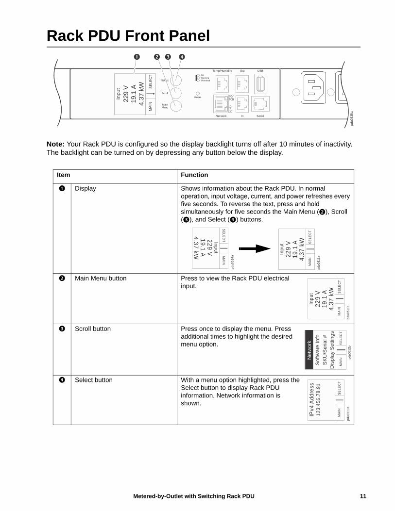
Note: Your Rack PDU is configured so the display backlight turns off after 10 minutes of inactivity. The backlight can be turned on by depressing any button below the display.
Item Function
Display Shows information about the Rack PDU. In normal operation, input voltage, current, and power refreshes every five seconds. To reverse the text, press and hold simultaneously for five seconds the Main Menu (), Scroll (), and Select () buttons.
Main Menu button Press to view the Rack PDU electrical input.
Scroll button Press once to display the menu. Press additional times to highlight the desired menu option.
Select button With a menu option highlighted, press the Select button to display Rack PDU information. Network information is shown.
pdu0
535
a
SerialNetwork In
OutTemp/Humidity USB
Reset
MainMenu
Select
Scroll
- Warning- OK
- Overload
x
SE
LE
CT
MA
IN
Inpu
t
229
V19
.1 A
4.3
7 kW
SE
LE
CT
MA
IN
Input
229
V19.1
A4.3
7kW
pdu0
514
a
SE
LEC
TM
AIN
Inp
ut22
9 V
19.1
A4.
37 k
W
pdu
051
1a
SE
LEC
TM
AIN
Inp
ut22
9 V
19.1
A4.
37 k
W
pdu
051
1a
pdu
0512b
SE
LE
CT
MA
IN
Dis
pla
y S
etti
ng
s
So
ftwa
re I
nfo
Ne
two
rk
SK
U/S
eria
l #
SE
LEC
TM
AIN
IPv4
Add
ress
12
3.4
56.7
8.91
pdu
051
3a
11Metered-by-Outlet with Switching Rack PDU
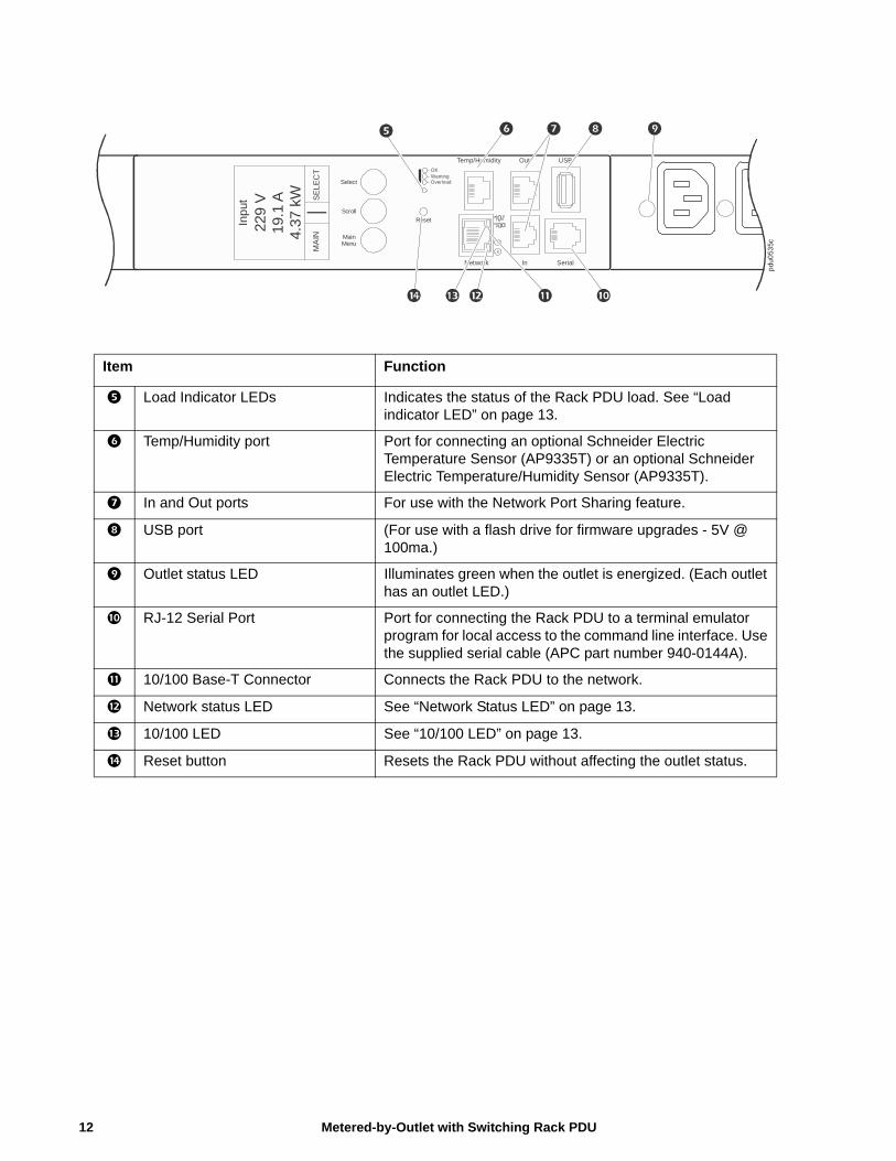
Item Function
Load Indicator LEDs Indicates the status of the Rack PDU load. See “Load indicator LED” on page 13.
Temp/Humidity port Port for connecting an optional Schneider Electric Temperature Sensor (AP9335T) or an optional Schneider Electric Temperature/Humidity Sensor (AP9335T).
In and Out ports For use with the Network Port Sharing feature.
USB port (For use with a flash drive for firmware upgrades - 5V @ 100ma.)
Outlet status LED Illuminates green when the outlet is energized. (Each outlet has an outlet LED.)
RJ-12 Serial Port Port for connecting the Rack PDU to a terminal emulator program for local access to the command line interface. Use the supplied serial cable (APC part number 940-0144A).
10/100 Base-T Connector Connects the Rack PDU to the network.
Network status LED See “Network Status LED” on page 13.
10/100 LED See “10/100 LED” on page 13.
Reset button Resets the Rack PDU without affecting the outlet status.p
du0
535c
SerialNetwork In
OutTemp/Humidity USB
Reset
MainMenu
Select
Scroll
- Warning- OK
- Overload
x
SE
LE
CT
MA
IN
Inp
ut
229
V19
.1 A
4.37
kW
Metered-by-Outlet with Switching Rack PDU12
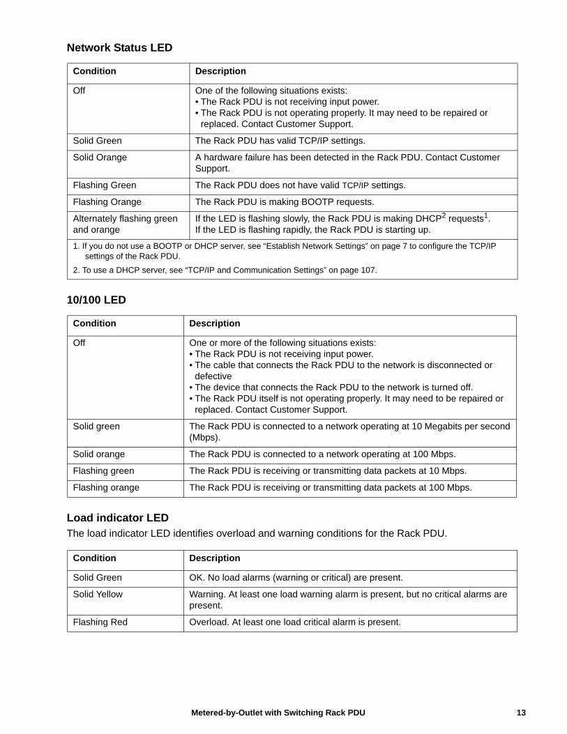
Network Status LED
10/100 LED
Load indicator LEDThe load indicator LED identifies overload and warning conditions for the Rack PDU.
Condition Description
Off One of the following situations exists:• The Rack PDU is not receiving input power.• The Rack PDU is not operating properly. It may need to be repaired or
replaced. Contact Customer Support.
Solid Green The Rack PDU has valid TCP/IP settings.
Solid Orange A hardware failure has been detected in the Rack PDU. Contact Customer Support.
Flashing Green The Rack PDU does not have valid TCP/IP settings.
Flashing Orange The Rack PDU is making BOOTP requests.
Alternately flashing green and orange
If the LED is flashing slowly, the Rack PDU is making DHCP2 requests1.If the LED is flashing rapidly, the Rack PDU is starting up.
1. If you do not use a BOOTP or DHCP server, see “Establish Network Settings” on page 7 to configure the TCP/IP settings of the Rack PDU.
2. To use a DHCP server, see “TCP/IP and Communication Settings” on page 107.
Condition Description
Off One or more of the following situations exists:• The Rack PDU is not receiving input power.• The cable that connects the Rack PDU to the network is disconnected or
defective• The device that connects the Rack PDU to the network is turned off.• The Rack PDU itself is not operating properly. It may need to be repaired or
replaced. Contact Customer Support.
Solid green The Rack PDU is connected to a network operating at 10 Megabits per second (Mbps).
Solid orange The Rack PDU is connected to a network operating at 100 Mbps.
Flashing green The Rack PDU is receiving or transmitting data packets at 10 Mbps.
Flashing orange The Rack PDU is receiving or transmitting data packets at 100 Mbps.
Condition Description
Solid Green OK. No load alarms (warning or critical) are present.
Solid Yellow Warning. At least one load warning alarm is present, but no critical alarms are present.
Flashing Red Overload. At least one load critical alarm is present.
13Metered-by-Outlet with Switching Rack PDU
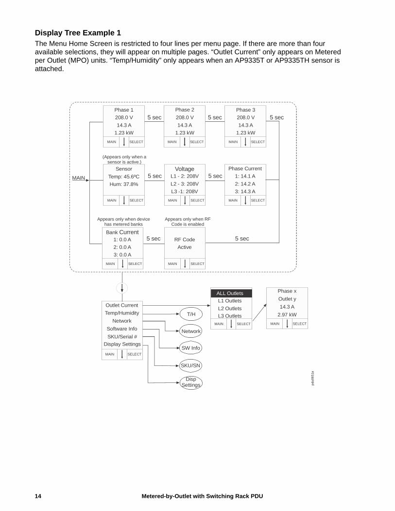
Display Tree Example 1The Menu Home Screen is restricted to four lines per menu page. If there are more than four available selections, they will appear on multiple pages. “Outlet Current” only appears on Metered per Outlet (MPO) units. “Temp/Humidity” only appears when an AP9335T or AP9335TH sensor is attached.
Phase x
Outlet y
14.3 A
2.97 kW
SELECTMAIN
pdu
065
1aTemp/Humidity
Software Info
SKU/Serial #
SELECTMAIN
Outlet Current
Display Settings
T/H
Network
SW Info
SKU/SN
Network
L1 Outlets
L2 Outlets
SELECTMAIN
L3 Outlets
ALL Outlets
5 sec 5 sec
5 sec
(Appears only when a sensor is active.)
SELECTMAIN
Phase 1 208.0 V
14.3 A
1.23 kW
Phase 2 208.0 V
14.3 A
1.23 kW
SELECTMAIN
Phase 3
208.0 V
14.3 A
1.23 kW
SELECTMAIN
Sensor
Temp: 45.6ºC
Hum: 37.8%
SELECTMAIN
Phase Current 1: 14.1 A
2: 14.2 A
3: 14.3 A
SELECTMAIN
VoltageL1 - 2: 208V
L2 - 3: 208V
L3 -1: 208V
SELECTMAIN
5 secMAIN
RF Code
Active
SELECTMAIN
Bank Current 1: 0.0 A
2: 0.0 A
3: 0.0 A
SELECTMAIN
5 sec
Appears only when device has metered banks
Appears only when RF Code is enabled
Disp Settings
5 sec
5 sec
Metered-by-Outlet with Switching Rack PDU14
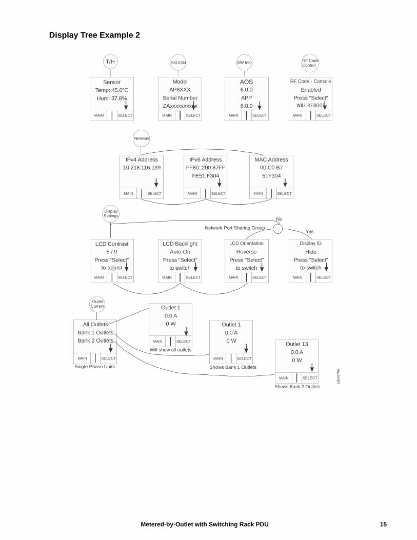
Display Tree Example 2
IPv4 Address 10.218.116.139
SELECTMAIN
All Outlets
Bank 1 Outlets
Bank 2 Outlets
SELECTMAIN
Network
DisplaySettings
pdu
067
9a
OutletCurrent
Sensor
Temp: 45.6ºC
Hum: 37.8%
SELECTMAIN SELECTMAIN
Model
AP8XXX
Serial Number
ZAxxxxxxxxxx
RF CodeControl
SW InfoSKU/SNT/H
SELECTMAIN
AOS6.0.0
APP
6.0.0
RF Code - Console
Enabled
SELECTMAIN
Press “Select”WILL REBOOT
IPv6 Address FF80::200:87FF
FE51:F304
SELECTMAIN
MAC Address 00 C0 B7
51F304
SELECTMAIN
LCD Contrast
5 / 9
Press “Select”
SELECTMAIN SELECTMAIN
LCD Backlight
Auto-On
Press “Select”
to switch
SELECTMAIN
LCD Orientation
Reverse
Press “Select”
to switch
Display ID
Hide
SELECTMAIN
Press “Select”
to switchto adjust
No
YesNetwork Port Sharing Group
Outlet 1
0.0 A
0 W
SELECTMAIN
Outlet 1
0.0 A
0 W
SELECTMAIN
Outlet 13
0.0 A
0 W
SELECTMAIN
Will show all outlets
Shows Bank 1 Outlets
Shows Bank 2 Outlets
Single Phase Units
15Metered-by-Outlet with Switching Rack PDU
Command Line Interface
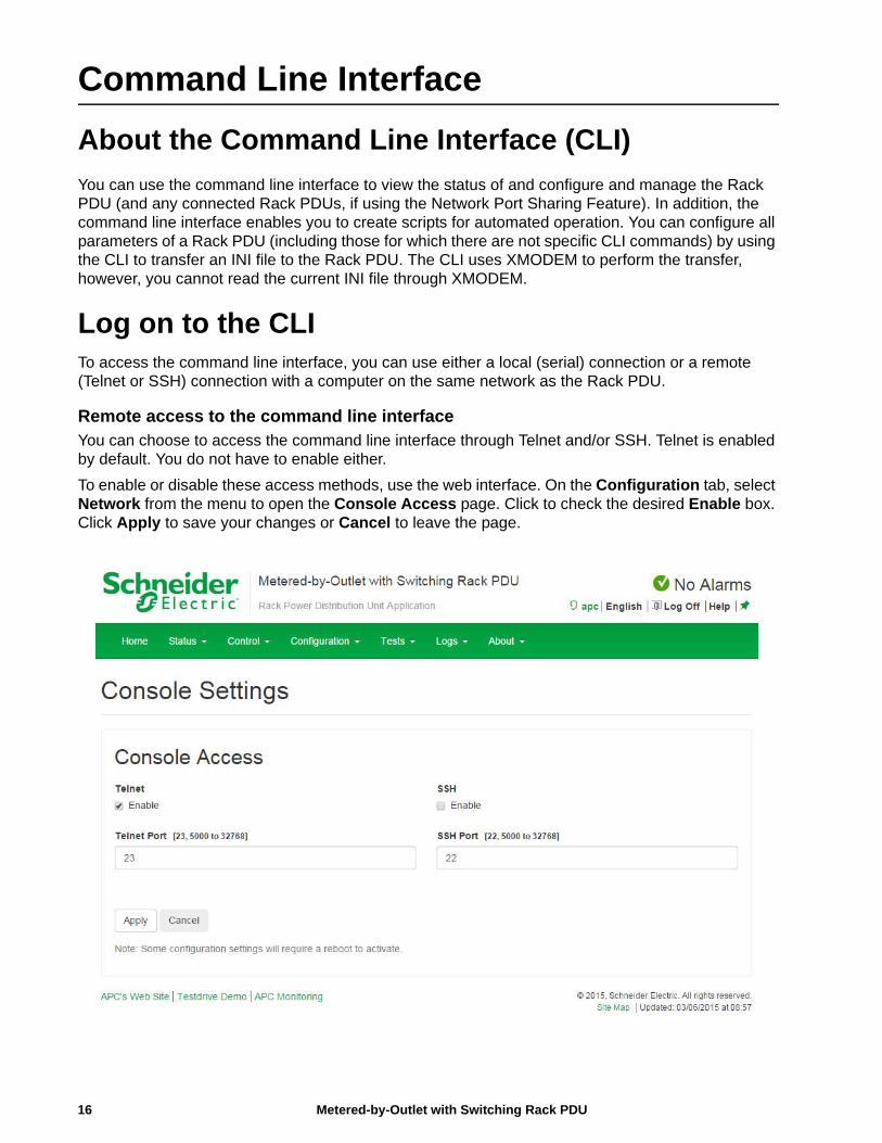
About the Command Line Interface (CLI)
You can use the command line interface to view the status of and configure and manage the Rack PDU (and any connected Rack PDUs, if using the Network Port Sharing Feature). In addition, the command line interface enables you to create scripts for automated operation. You can configure all parameters of a Rack PDU (including those for which there are not specific CLI commands) by using the CLI to transfer an INI file to the Rack PDU. The CLI uses XMODEM to perform the transfer, however, you cannot read the current INI file through XMODEM.
Log on to the CLITo access the command line interface, you can use either a local (serial) connection or a remote (Telnet or SSH) connection with a computer on the same network as the Rack PDU.
Remote access to the command line interfaceYou can choose to access the command line interface through Telnet and/or SSH. Telnet is enabled by default. You do not have to enable either.
To enable or disable these access methods, use the web interface. On the Configuration tab, select Network from the menu to open the Console Access page. Click to check the desired Enable box. Click Apply to save your changes or Cancel to leave the page.
Metered-by-Outlet with Switching Rack PDU16
Telnet for basic accessTelnet provides the basic security of authentication by user name and password, but not the high-security benefits of encryption.
To use Telnet to access the command line interface:
1. From a computer that has access to the network on which the Rack PDU is installed, at a command prompt, type telnet and the IP address for the Rack PDU (for example, telnet 139.225.6.133, when the Rack PDU uses the default Telnet port of 23), and press ENTER.
If the Rack PDU uses a non-default port number (from 5000 to 32768), you must include a colon or a space, depending on your Telnet client, between the IP address (or DNS name) and the port number. (These are commands for general usage: Some clients do not allow you to specify the port as an argument and some types of Linux might want extra commands).
2. Enter the user name and password (by default, apc and apc for the Super User).
If you cannot remember your user name or password, see “Recovering from a Lost Password” on page 10.
SSH for high-security accessIf you use the high security of SSL for the Web interface, use SSH for access to the command line interface. SSH encrypts user names, passwords, and transmitted data. The interface, user accounts, and user access rights are the same whether you access the command line interface through SSH or Telnet, but to use SSH, you must first configure SSH and have an SSH client program installed on your computer.
Local access to the command line interface
For local access, use a computer that connects to the Rack PDU through the serial port to access the command line interface:
1. Select a serial port at the computer and disable any service that uses that port.
2. Connect the serial cable (Schneider Electric part number 940-0144A) from the selected serial port on the computer to the Serial port on the Rack PDU.
3. Run a terminal program (e.g., HyperTerminal) and configure the selected port for 9600 bps, 8 data bits, no parity, 1 stop bit, and no flow control.
4. Press ENTER. At the prompts, enter your user name and password.
17Metered-by-Outlet with Switching Rack PDU
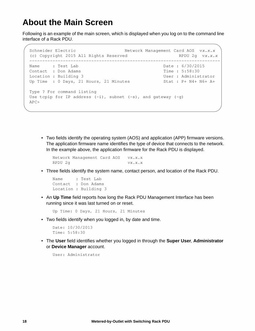
About the Main ScreenFollowing is an example of the main screen, which is displayed when you log on to the command line interface of a Rack PDU.
• Two fields identify the operating system (AOS) and application (APP) firmware versions. The application firmware name identifies the type of device that connects to the network. In the example above, the application firmware for the Rack PDU is displayed.
Network Management Card AOS vx.x.xRPDU 2g vx.x.x
• Three fields identify the system name, contact person, and location of the Rack PDU.
Name : Test LabContact : Don AdamsLocation : Building 3
• An Up Time field reports how long the Rack PDU Management Interface has been running since it was last turned on or reset.
Up Time: 0 Days, 21 Hours, 21 Minutes
• Two fields identify when you logged in, by date and time.
Date: 10/30/2013Time: 5:58:30
• The User field identifies whether you logged in through the Super User, Administrator or Device Manager account.
User: Administrator
Schneider Electric Network Management Card AOS vx.x.x(c) Copyright 2015 All Rights Reserved RPDU 2g vx.x.x--------------------------------------------------------------------------Name : Test Lab Date : 6/30/2015Contact : Don Adams Time : 5:58:30Location : Building 3 User : AdministratorUp Time : 0 Days, 21 Hours, 21 Minutes Stat : P+ N4+ N6+ A+
Type ? For command listingUse tcpip for IP address (-i), subnet (-s), and gateway (-g)APC>
Metered-by-Outlet with Switching Rack PDU18
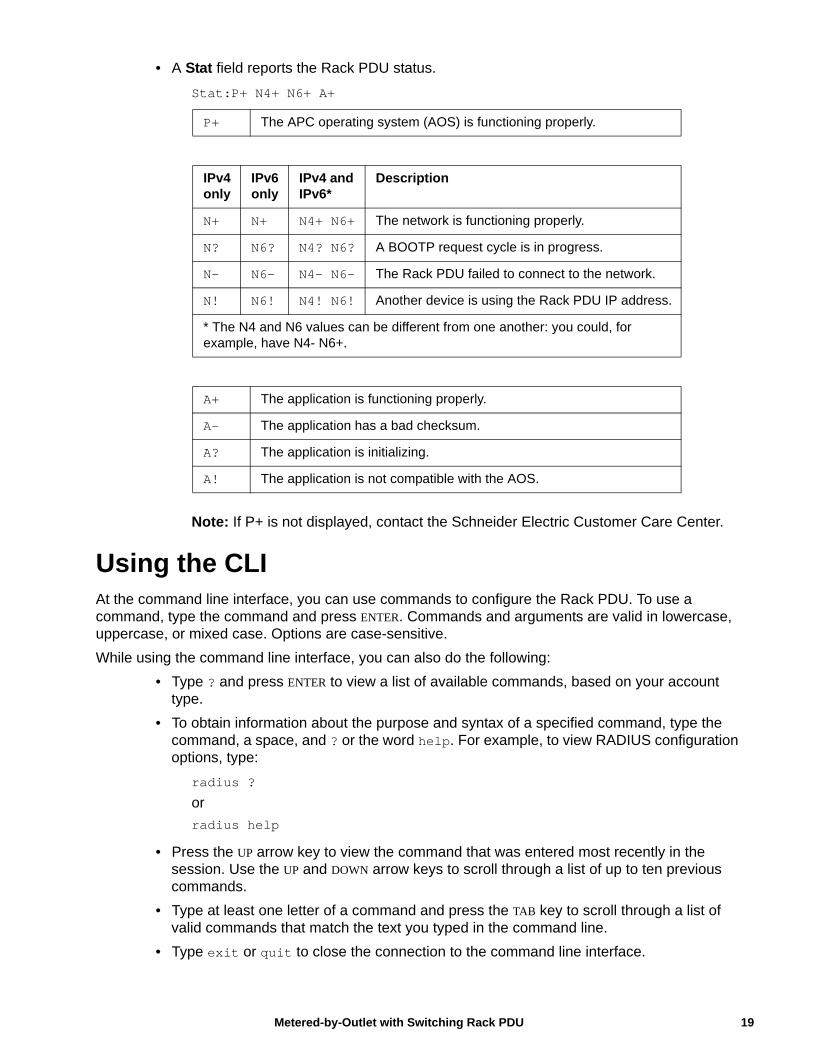
• A Stat field reports the Rack PDU status.
Stat:P+ N4+ N6+ A+
Note: If P+ is not displayed, contact the Schneider Electric Customer Care Center.
Using the CLIAt the command line interface, you can use commands to configure the Rack PDU. To use a command, type the command and press ENTER. Commands and arguments are valid in lowercase, uppercase, or mixed case. Options are case-sensitive.
While using the command line interface, you can also do the following:
• Type ? and press ENTER to view a list of available commands, based on your account type.
• To obtain information about the purpose and syntax of a specified command, type the command, a space, and ? or the word help. For example, to view RADIUS configuration options, type:
radius ?
or
radius help
• Press the UP arrow key to view the command that was entered most recently in the session. Use the UP and DOWN arrow keys to scroll through a list of up to ten previous commands.
• Type at least one letter of a command and press the TAB key to scroll through a list of valid commands that match the text you typed in the command line.
• Type exit or quit to close the connection to the command line interface.
P+ The APC operating system (AOS) is functioning properly.
IPv4 only
IPv6 only
IPv4 and IPv6*
Description
N+ N+ N4+ N6+ The network is functioning properly.
N? N6? N4? N6? A BOOTP request cycle is in progress.
N– N6- N4- N6- The Rack PDU failed to connect to the network.
N! N6! N4! N6! Another device is using the Rack PDU IP address.
* The N4 and N6 values can be different from one another: you could, for example, have N4- N6+.
A+ The application is functioning properly.
A– The application has a bad checksum.
A? The application is initializing.
A! The application is not compatible with the AOS.
19Metered-by-Outlet with Switching Rack PDU
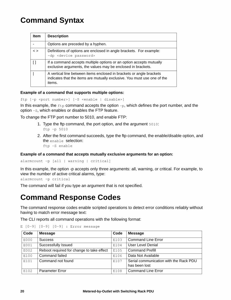
Command Syntax
Example of a command that supports multiple options:
ftp [-p <port number>] [-S <enable | disable>]
In this example, the ftp command accepts the option -p, which defines the port number, and the option -S, which enables or disables the FTP feature.
To change the FTP port number to 5010, and enable FTP:
1. Type the ftp command, the port option, and the argument 5010:ftp -p 5010
2. After the first command succeeds, type the ftp command, the enable/disable option, and the enable selection:ftp -S enable
Example of a command that accepts mutually exclusive arguments for an option:
alarmcount -p [all | warning | critical]
In this example, the option -p accepts only three arguments: all, warning, or critical. For example, to view the number of active critical alarms, type:alarmcount -p critical
The command will fail if you type an argument that is not specified.
Command Response CodesThe command response codes enable scripted operations to detect error conditions reliably without having to match error message text:
The CLI reports all command operations with the following format:
E [0-9] [0-9] [0-9] : Error message
Item Description
- Options are preceded by a hyphen.
< > Definitions of options are enclosed in angle brackets. For example: -dp <device password>
[ ] If a command accepts multiple options or an option accepts mutually exclusive arguments, the values may be enclosed in brackets.
| A vertical line between items enclosed in brackets or angle brackets indicates that the items are mutually exclusive. You must use one of the items.
Code Message Code Message
E000 Success E103 Command Line Error
E001 Successfully Issued E104 User Level Denial
E002 Reboot required for change to take effect E105 Command Prefill
E100 Command failed E106 Data Not Available
E101 Command not found E107 Serial communication with the Rack PDU has been lost
E102 Parameter Error E108 Command Line Error
Metered-by-Outlet with Switching Rack PDU20
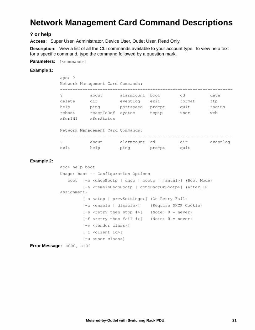
Network Management Card Command Descriptions? or helpAccess: Super User, Administrator, Device User, Outlet User, Read Only
Description: View a list of all the CLI commands available to your account type. To view help text for a specific command, type the command followed by a question mark.
Parameters: [<command>]
Example 1:
apc> ?Network Management Card Commands:---------------------------------------------------------------------? about alarmcount boot cd datedelete dir eventlog exit format ftphelp ping portspeed prompt quit radiusreboot resetToDef system tcpip user webxferINI xferStatus
Network Management Card Commands:---------------------------------------------------------------------? about alarmcount cd dir eventlogexit help ping prompt quit
Example 2: apc> help boot
Usage: boot -- Configuration Options
boot [-b <dhcpBootp | dhcp | bootp | manual>] (Boot Mode)
[-a <remainDhcpBootp | gotoDhcpOrBootp>] (After IP Assignment)
[-o <stop | prevSettings>] (On Retry Fail)
[-c <enable | disable>] (Require DHCP Cookie)
[-s <retry then stop #>] (Note: 0 = never)
[-f <retry then fail #>] (Note: 0 = never)
[-v <vendor class>]
[-i <client id>]
[-u <user class>]
Error Message: E000, E102
21Metered-by-Outlet with Switching Rack PDU
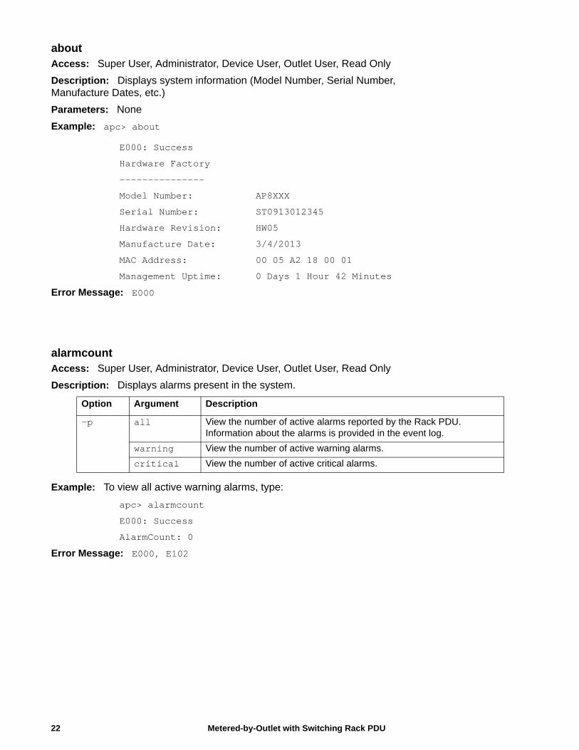
aboutAccess: Super User, Administrator, Device User, Outlet User, Read Only
Description: Displays system information (Model Number, Serial Number, Manufacture Dates, etc.)
Parameters: None
Example: apc> about
E000: Success
Hardware Factory
---------------
Model Number: AP8XXX
Serial Number: ST0913012345
Hardware Revision: HW05
Manufacture Date: 3/4/2013
MAC Address: 00 05 A2 18 00 01
Management Uptime: 0 Days 1 Hour 42 Minutes
Error Message: E000
alarmcountAccess: Super User, Administrator, Device User, Outlet User, Read Only
Description: Displays alarms present in the system.
Example: To view all active warning alarms, type:
apc> alarmcount
E000: Success
AlarmCount: 0
Error Message: E000, E102
Option Argument Description
-p all View the number of active alarms reported by the Rack PDU. Information about the alarms is provided in the event log.
warning View the number of active warning alarms.
critical View the number of active critical alarms.
Metered-by-Outlet with Switching Rack PDU22
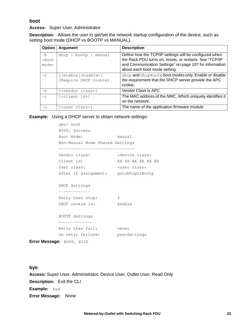
bootAccess: Super User, Administrator
Description: Allows the user to get/set the network startup configuration of the device, such as setting boot mode (DHCP vs BOOTP vs MANUAL).
Example: Using a DHCP server to obtain network settings:
apc> boot
E000: Success
Boot Mode: manual
Non-Manual Mode Shared Settings
-------------------------------
Vendor class: <device class>
Client id: XX XX XX XX XX XX
User class: <user class>
After IP assignment: gotoDhcpOrBootp
DHCP Settings
-------------
Retry then stop: 4
DHCP cookie is: enable
BOOTP Settings
--------------Retry then fail: never
On retry failure: prevSettings
Error Message: E000, E102
byeAccess: Super User, Administrator, Device User, Outlet User, Read Only
Description: Exit the CLI
Example: bye
Error Message: None
Option Argument Description
-b<boot mode>
dhcp | bootp | manual Define how the TCP/IP settings will be configured when the Rack PDU turns on, resets, or restarts. See “TCP/IP and Communication Settings” on page 107 for information about each boot mode setting.
-c [<enable | disable>] (Require DHCP Cookie)
dhcp and dhcpBootp boot modes only. Enable or disable the requirement that the DHCP server provide the APC cookie.
-v [<vendor class>] Vendor Class is APC
-i [<client id>] The MAC address of the NMC, Which uniquely identifies it on the network.
-u [<user class>] The name of the application firmware module.
23Metered-by-Outlet with Switching Rack PDU
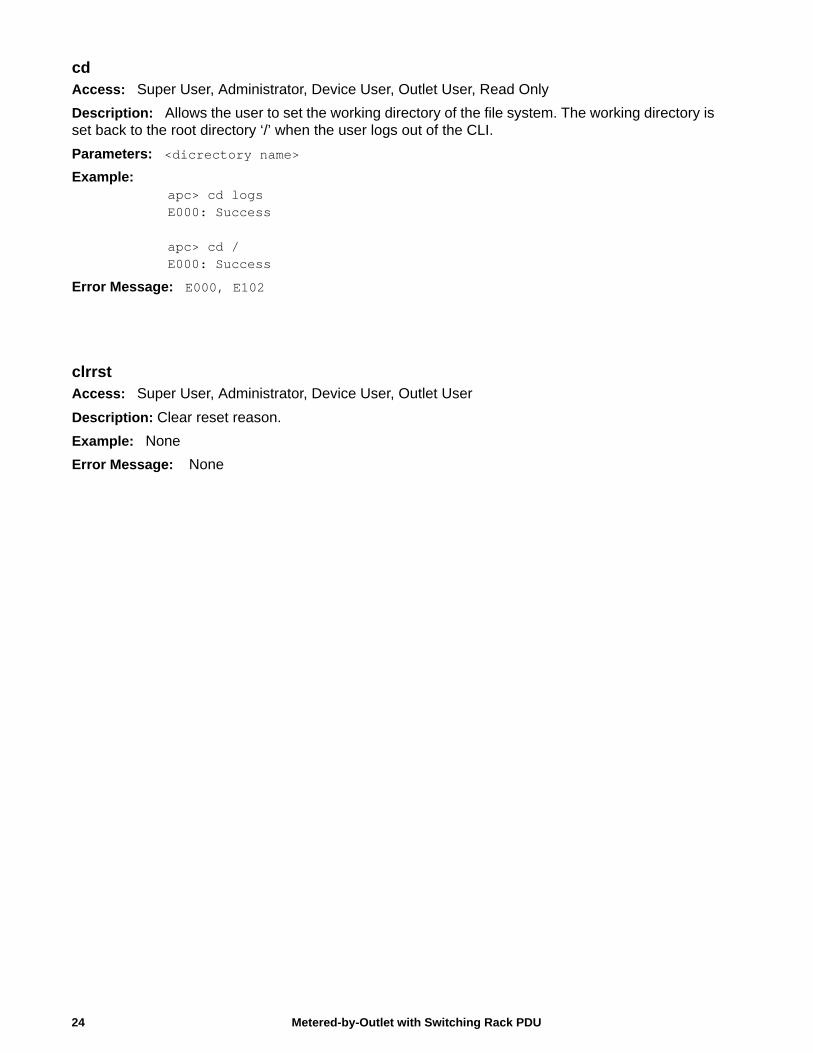
cdAccess: Super User, Administrator, Device User, Outlet User, Read Only
Description: Allows the user to set the working directory of the file system. The working directory is set back to the root directory ‘/’ when the user logs out of the CLI.
Parameters: <dicrectory name>
Example: apc> cd logsE000: Success
apc> cd /E000: Success
Error Message: E000, E102
clrrst Access: Super User, Administrator, Device User, Outlet User
Description: Clear reset reason.
Example: None
Error Message: None
Metered-by-Outlet with Switching Rack PDU24
25Metered-by-Outlet with Switching Rack PDU
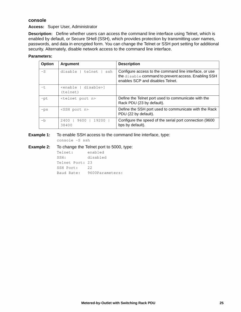
consoleAccess: Super User, Administrator
Description: Define whether users can access the command line interface using Telnet, which is enabled by default, or Secure SHell (SSH), which provides protection by transmitting user names, passwords, and data in encrypted form. You can change the Telnet or SSH port setting for additional security. Alternately, disable network access to the command line interface.
Parameters:
Example 1: To enable SSH access to the command line interface, type: console -S ssh
Example 2: To change the Telnet port to 5000, type: Telnet: enabledSSH: disabledTelnet Port: 23SSH Port: 22Baud Rate: 9600Parameters:
Option Argument Description
-S disable | telnet | ssh Configure access to the command line interface, or use the disable command to prevent access. Enabling SSH enables SCP and disables Telnet.
-t <enable | disable>] (telnet)
-pt <telnet port n> Define the Telnet port used to communicate with the Rack PDU (23 by default).
-ps <SSH port n> Define the SSH port used to communicate with the Rack PDU (22 by default).
-b 2400 | 9600 | 19200 | 38400
Configure the speed of the serial port connection (9600 bps by default).
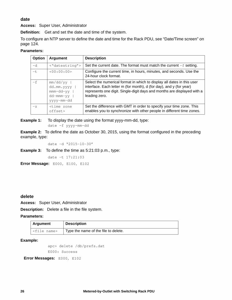
dateAccess: Super User, Administrator
Definition: Get and set the date and time of the system.
To configure an NTP server to define the date and time for the Rack PDU, see “Date/Time screen” on page 124.
Parameters:
Example 1: To display the date using the format yyyy-mm-dd, type:date -f yyyy-mm-dd
Example 2: To define the date as October 30, 2015, using the format configured in the preceding example, type:
date -d “2015-10-30”
Example 3: To define the time as 5:21:03 p.m., type:
date -t 17:21:03
Error Message: E000, E100, E102
deleteAccess: Super User, Administrator
Description: Delete a file in the file system.
Parameters:
Example: apc> delete /db/prefs.dat
E000: Success
Error Messages: E000, E102
Option Argument Description
-d <“datestring”> Set the current date. The format must match the current -f setting.
-t <00:00:00> Configure the current time, in hours, minutes, and seconds. Use the 24-hour clock format.
-f mm/dd/yy | dd.mm.yyyy | mmm-dd-yy | dd-mmm-yy | yyyy-mm-dd
Select the numerical format in which to display all dates in this user interface. Each letter m (for month), d (for day), and y (for year) represents one digit. Single-digit days and months are displayed with a leading zero.
-z <time zone offset>
Set the difference with GMT in order to specify your time zone. This enables you to synchronize with other people in different time zones.
Argument Description
<file name> Type the name of the file to delete.
Metered-by-Outlet with Switching Rack PDU26
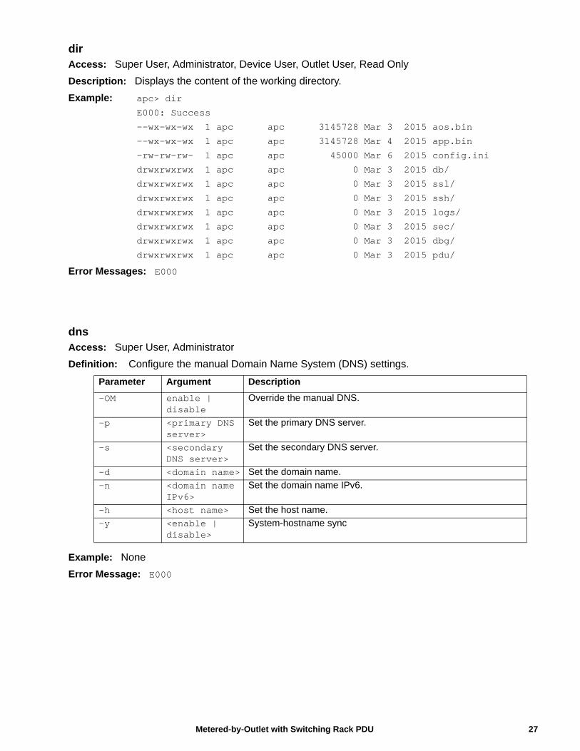
dirAccess: Super User, Administrator, Device User, Outlet User, Read Only
Description: Displays the content of the working directory.
Example: apc> dir
E000: Success
--wx-wx-wx 1 apc apc 3145728 Mar 3 2015 aos.bin
--wx-wx-wx 1 apc apc 3145728 Mar 4 2015 app.bin
-rw-rw-rw- 1 apc apc 45000 Mar 6 2015 config.ini
drwxrwxrwx 1 apc apc 0 Mar 3 2015 db/
drwxrwxrwx 1 apc apc 0 Mar 3 2015 ssl/
drwxrwxrwx 1 apc apc 0 Mar 3 2015 ssh/
drwxrwxrwx 1 apc apc 0 Mar 3 2015 logs/
drwxrwxrwx 1 apc apc 0 Mar 3 2015 sec/
drwxrwxrwx 1 apc apc 0 Mar 3 2015 dbg/
drwxrwxrwx 1 apc apc 0 Mar 3 2015 pdu/
Error Messages: E000
dnsAccess: Super User, Administrator
Definition: Configure the manual Domain Name System (DNS) settings.
Example: None
Error Message: E000
Parameter Argument Description
-OM enable | disable
Override the manual DNS.
-p <primary DNS server>
Set the primary DNS server.
-s <secondary DNS server>
Set the secondary DNS server.
-d <domain name> Set the domain name.
-n <domain name IPv6>
Set the domain name IPv6.
-h <host name> Set the host name.
-y <enable | disable>
System-hostname sync
27Metered-by-Outlet with Switching Rack PDU
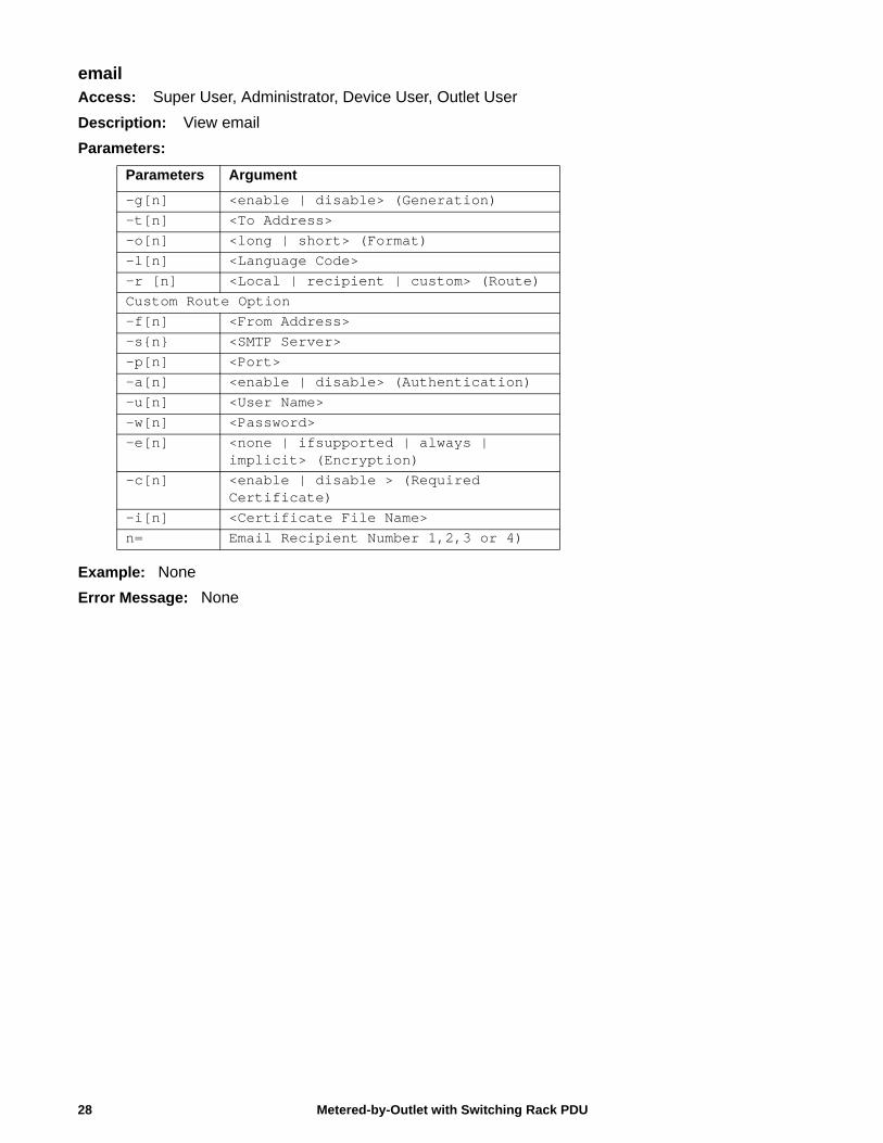
emailAccess: Super User, Administrator, Device User, Outlet User
Description: View email
Parameters:
Example: None
Error Message: None
Parameters Argument
-g[n] <enable | disable> (Generation)-t[n] <To Address>-o[n] <long | short> (Format)-l[n] <Language Code>-r [n] <Local | recipient | custom> (Route)Custom Route Option-f[n] <From Address>-s{n} <SMTP Server>-p[n] <Port>-a[n] <enable | disable> (Authentication)-u[n] <User Name>-w[n] <Password>-e[n] <none | ifsupported | always |
implicit> (Encryption)-c[n] <enable | disable > (Required
Certificate)-i[n] <Certificate File Name>n= Email Recipient Number 1,2,3 or 4)
Metered-by-Outlet with Switching Rack PDU28
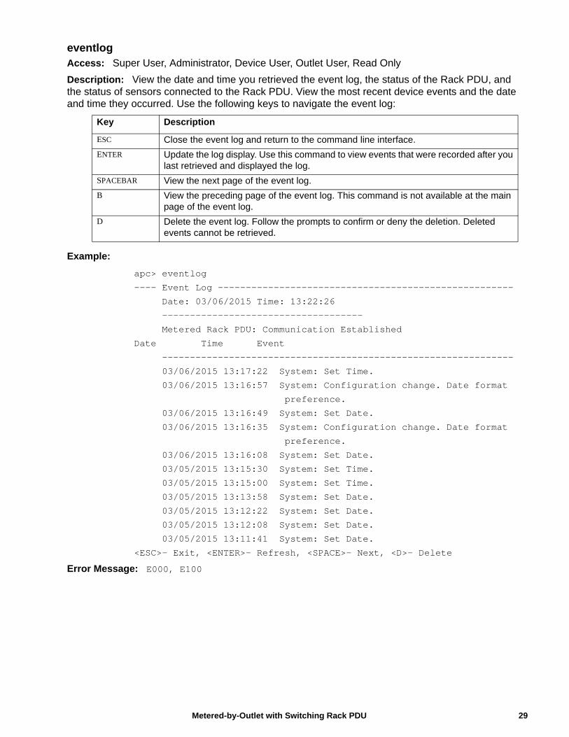
eventlogAccess: Super User, Administrator, Device User, Outlet User, Read Only
Description: View the date and time you retrieved the event log, the status of the Rack PDU, and the status of sensors connected to the Rack PDU. View the most recent device events and the date and time they occurred. Use the following keys to navigate the event log:
Example:
apc> eventlog
---- Event Log -----------------------------------------------------
Date: 03/06/2015 Time: 13:22:26
------------------------------------
Metered Rack PDU: Communication Established
Date Time Event
---------------------------------------------------------------
03/06/2015 13:17:22 System: Set Time.
03/06/2015 13:16:57 System: Configuration change. Date format
preference.
03/06/2015 13:16:49 System: Set Date.
03/06/2015 13:16:35 System: Configuration change. Date format
preference.
03/06/2015 13:16:08 System: Set Date.
03/05/2015 13:15:30 System: Set Time.
03/05/2015 13:15:00 System: Set Time.
03/05/2015 13:13:58 System: Set Date.
03/05/2015 13:12:22 System: Set Date.
03/05/2015 13:12:08 System: Set Date.
03/05/2015 13:11:41 System: Set Date.
<ESC>- Exit, <ENTER>- Refresh, <SPACE>- Next, <D>- Delete
Error Message: E000, E100
Key Description
ESC Close the event log and return to the command line interface.
ENTER Update the log display. Use this command to view events that were recorded after you last retrieved and displayed the log.
SPACEBAR View the next page of the event log.
B View the preceding page of the event log. This command is not available at the main page of the event log.
D Delete the event log. Follow the prompts to confirm or deny the deletion. Deleted events cannot be retrieved.
29Metered-by-Outlet with Switching Rack PDU
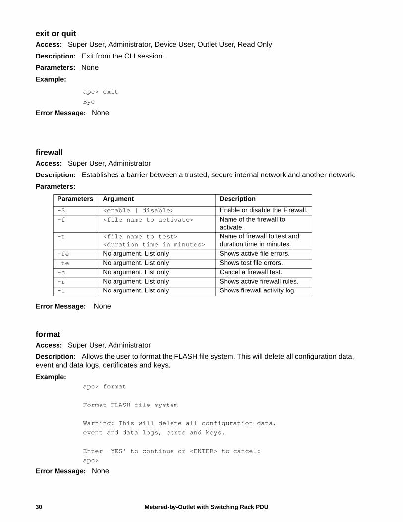
exit or quitAccess: Super User, Administrator, Device User, Outlet User, Read Only
Description: Exit from the CLI session.
Parameters: None
Example:
apc> exit
Bye
Error Message: None
firewallAccess: Super User, Administrator
Description: Establishes a barrier between a trusted, secure internal network and another network.
Parameters:
Error Message: None
formatAccess: Super User, Administrator
Description: Allows the user to format the FLASH file system. This will delete all configuration data, event and data logs, certificates and keys.
Example: apc> format
Format FLASH file system
Warning: This will delete all configuration data,event and data logs, certs and keys.
Enter 'YES' to continue or <ENTER> to cancel:apc>
Error Message: None
Parameters Argument Description
-S <enable | disable> Enable or disable the Firewall.
-f <file name to activate> Name of the firewall to activate.
-t <file name to test> <duration time in minutes>
Name of firewall to test and duration time in minutes.
-fe No argument. List only Shows active file errors.
-te No argument. List only Shows test file errors.
-c No argument. List only Cancel a firewall test.
-r No argument. List only Shows active firewall rules.
-l No argument. List only Shows firewall activity log.
Metered-by-Outlet with Switching Rack PDU30
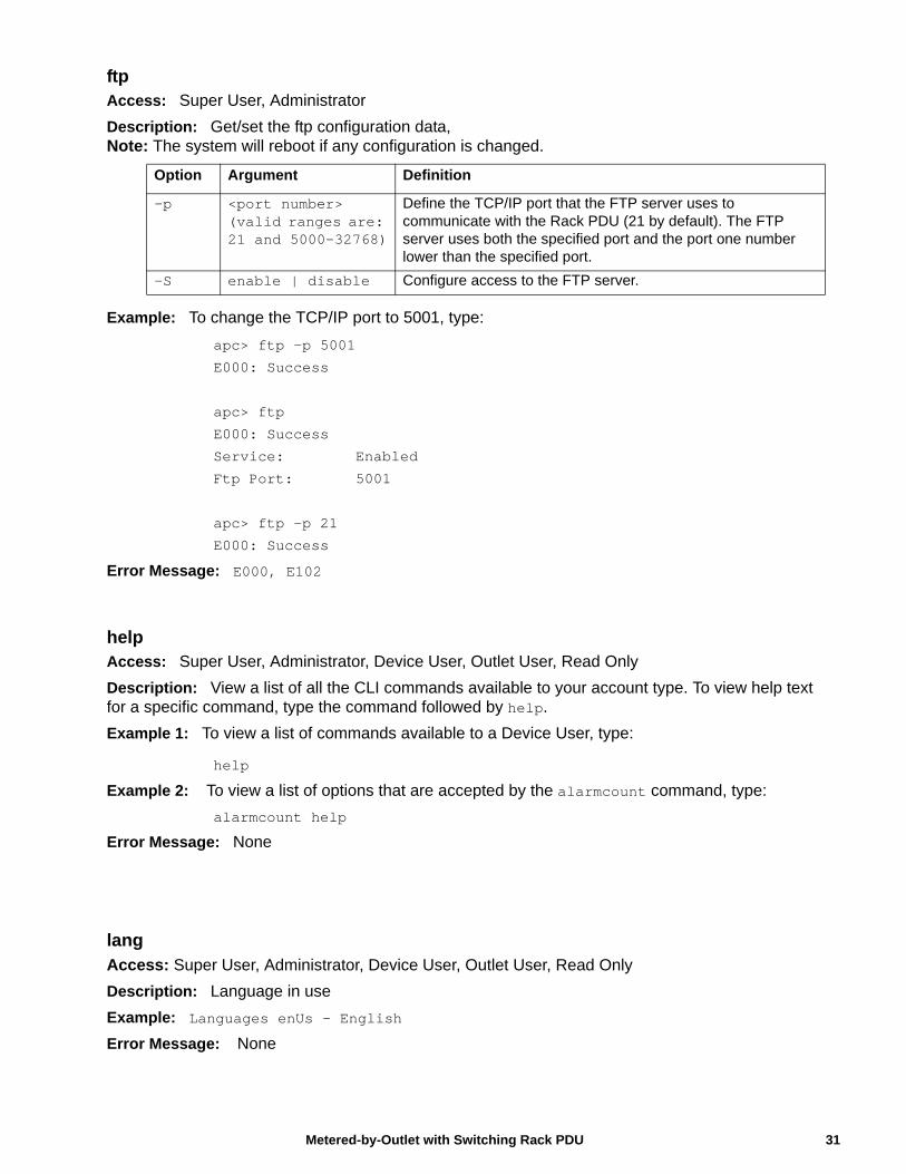
ftpAccess: Super User, Administrator
Description: Get/set the ftp configuration data,Note: The system will reboot if any configuration is changed.
Example: To change the TCP/IP port to 5001, type:
apc> ftp -p 5001
E000: Success
apc> ftp
E000: Success
Service: Enabled
Ftp Port: 5001
apc> ftp -p 21
E000: Success
Error Message: E000, E102
helpAccess: Super User, Administrator, Device User, Outlet User, Read Only
Description: View a list of all the CLI commands available to your account type. To view help text for a specific command, type the command followed by help.
Example 1: To view a list of commands available to a Device User, type:
help
Example 2: To view a list of options that are accepted by the alarmcount command, type:
alarmcount help
Error Message: None
langAccess: Super User, Administrator, Device User, Outlet User, Read Only
Description: Language in use
Example: Languages enUs - English
Error Message: None
Option Argument Definition
-p <port number> (valid ranges are: 21 and 5000-32768)
Define the TCP/IP port that the FTP server uses to communicate with the Rack PDU (21 by default). The FTP server uses both the specified port and the port one number lower than the specified port.
-S enable | disable Configure access to the FTP server.
31Metered-by-Outlet with Switching Rack PDU
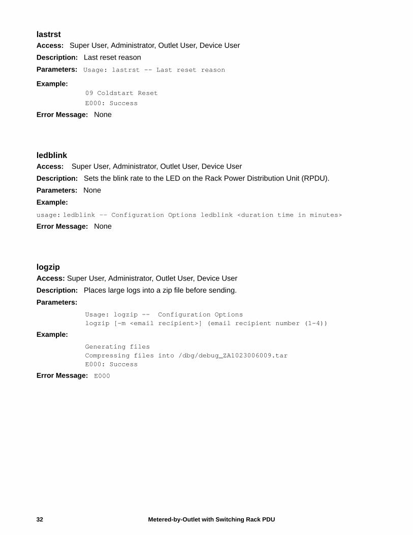
lastrst Access: Super User, Administrator, Outlet User, Device User
Description: Last reset reason
Parameters: Usage: lastrst -- Last reset reason
Example: 09 Coldstart Reset
E000: Success
Error Message: None
ledblinkAccess: Super User, Administrator, Outlet User, Device User
Description: Sets the blink rate to the LED on the Rack Power Distribution Unit (RPDU).
Parameters: None
Example:
usage: ledblink -- Configuration Options ledblink <duration time in minutes>
Error Message: None
logzipAccess: Super User, Administrator, Outlet User, Device User
Description: Places large logs into a zip file before sending.
Parameters:
Usage: logzip -- Configuration Optionslogzip [-m <email recipient>] (email recipient number (1-4))
Example:
Generating filesCompressing files into /dbg/debug_ZA1023006009.tarE000: Success
Error Message: E000
Metered-by-Outlet with Switching Rack PDU32
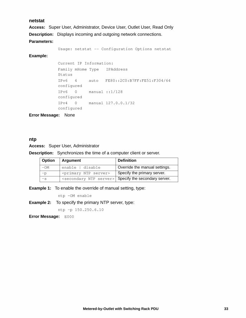
netstatAccess: Super User, Administrator, Device User, Outlet User, Read Only
Description: Displays incoming and outgoing network connections.
Parameters:
Usage: netstat -- Configuration Options netstat
Example:
Current IP Information:
Family mHome Type IPAddress Status
IPv6 4 auto FE80::2C0:B7FF:FE51:F304/64 configured
IPv6 0 manual ::1/128 configured
IPv4 0 manual 127.0.0.1/32 configured
Error Message: None
ntpAccess: Super User, Administrator
Description: Synchronizes the time of a computer client or server.
Example 1: To enable the override of manual setting, type:
ntp -OM enable
Example 2: To specify the primary NTP server, type:
ntp -p 150.250.6.10
Error Message: E000
Option Argument Definition
-OM enable | disable Override the manual settings.
-p <primary NTP server> Specify the primary server.
-s <secondary NTP server> Specify the secondary server.
33Metered-by-Outlet with Switching Rack PDU
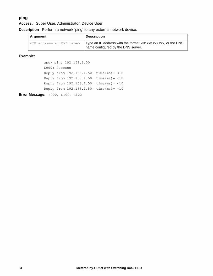
pingAccess: Super User, Administrator, Device User
Description Perform a network ‘ping’ to any external network device.
Example:
apc> ping 192.168.1.50
E000: Success
Reply from 192.168.1.50: time(ms)= <10
Reply from 192.168.1.50: time(ms)= <10
Reply from 192.168.1.50: time(ms)= <10
Reply from 192.168.1.50: time(ms)= <10
Error Message: E000, E100, E102
Argument Description
<IP address or DNS name> Type an IP address with the format xxx.xxx.xxx.xxx, or the DNS name configured by the DNS server.
Metered-by-Outlet with Switching Rack PDU34
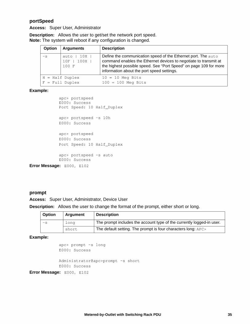
portSpeedAccess: Super User, Administrator
Description: Allows the user to get/set the network port speed.Note: The system will reboot if any configuration is changed.
Example:
apc> portspeedE000: SuccessPort Speed: 10 Half_Duplex
apc> portspeed -s 10hE000: Success
apc> portspeedE000: SuccessPort Speed: 10 Half_Duplex
apc> portspeed -s autoE000: Success
Error Message: E000, E102
promptAccess: Super User, Administrator, Device User
Description: Allows the user to change the format of the prompt, either short or long.
Example:
apc> prompt –s longE000: Success
Administrator@apc>prompt –s shortE000: Success
Error Message: E000, E102
Option Arguments Description
-s auto | 10H | 10F | 100H | 100 F
Define the communication speed of the Ethernet port. The auto command enables the Ethernet devices to negotiate to transmit at the highest possible speed. See “Port Speed” on page 109 for more information about the port speed settings.
H = Half Duplex F = Full Duplex
10 = 10 Meg Bits100 = 100 Meg Bits
Option Argument Description
-s long The prompt includes the account type of the currently logged-in user.
short The default setting. The prompt is four characters long: APC>
35Metered-by-Outlet with Switching Rack PDU
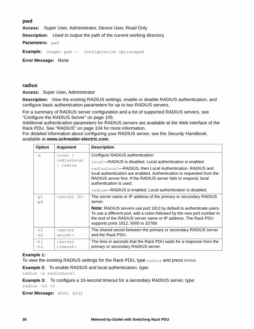
pwdAccess: Super User, Administrator, Device User, Read Only
Description: Used to output the path of the current working directory.
Parameters: pwd
Example: Usage: pwd -- Configuration Optionspwd
Error Message: None
radiusAccess: Super User, Administrator
Description: View the existing RADIUS settings, enable or disable RADIUS authentication, and configure basic authentication parameters for up to two RADIUS servers.
For a summary of RADIUS server configuration and a list of supported RADIUS servers, see “Configure the RADIUS Server” on page 105.Additional authentication parameters for RADIUS servers are available at the Web interface of the Rack PDU. See “RADIUS” on page 104 for more information.For detailed information about configuring your RADIUS server, see the Security Handbook, available at www.schneider-electric.com.
Example 1: To view the existing RADIUS settings for the Rack PDU, type radius and press ENTER.
Example 2: To enable RADIUS and local authentication, type:radius -a radiusLocal
Example 3: To configure a 10-second timeout for a secondary RADIUS server, type:radius -t2 10
Error Message: E000, E102
Option Argument Description
-a local | radiusLocal | radius
Configure RADIUS authentication:
local—RADIUS is disabled. Local authentication is enabled.
radiusLocal—RADIUS, then Local Authentication. RADIUS and local authentication are enabled. Authentication is requested from the RADIUS server first. If the RADIUS server fails to respond, local authentication is used.
radius—RADIUS is enabled. Local authentication is disabled.
-p1-p2
<server IP> The server name or IP address of the primary or secondary RADIUS server.
Note: RADIUS servers use port 1812 by default to authenticate users. To use a different port, add a colon followed by the new port number to the end of the RADIUS server name or IP address. The Rack PDU supports ports 1812, 5000 to 32768.
-s1-s2
<server secret>
The shared secret between the primary or secondary RADIUS server and the Rack PDU.
-t1-t2
<server timeout>
The time in seconds that the Rack PDU waits for a response from the primary or secondary RADIUS server.
Metered-by-Outlet with Switching Rack PDU36
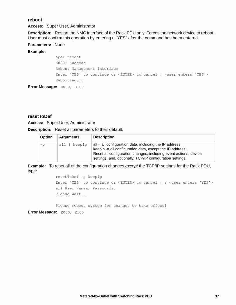
rebootAccess: Super User, Administrator
Description: Restart the NMC interface of the Rack PDU only. Forces the network device to reboot. User must confirm this operation by entering a “YES” after the command has been entered.
Parameters: None
Example:apc> reboot
E000: Success
Reboot Management Interface
Enter 'YES' to continue or <ENTER> to cancel : <user enters ‘YES’>
Rebooting...
Error Message: E000, E100
resetToDefAccess: Super User, Administrator
Description: Reset all parameters to their default.
Example: To reset all of the configuration changes except the TCP/IP settings for the Rack PDU, type:
resetToDef -p keepip
Enter 'YES' to continue or <ENTER> to cancel : : <user enters ‘YES’>
all User Names, Passwords.
Please wait...
Please reboot system for changes to take effect!
Error Message: E000, E100
Option Arguments Description
-p all | keepip all = all configuration data, including the IP address.keepip -= all configuration data, except the IP address.Reset all configuration changes, including event actions, device settings, and, optionally, TCP/IP configuration settings.
37Metered-by-Outlet with Switching Rack PDU
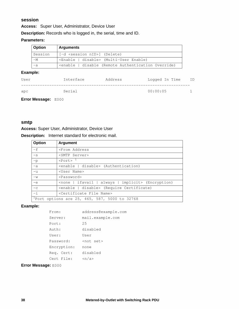
sessionAccess: Super User, Administrator, Device User
Description: Records who is logged in, the serial, time and ID.
Parameters:
Example:
User Interface Address Logged In Time ID
------------------------------------------------------------------------
apc Serial 00:00:05 1
Error Message: E000
smtpAccess: Super User, Administrator, Device User
Description: Internet standard for electronic mail.
Example: From: [email protected]
Server: mail.example.com
Port: 25
Auth: disabled
User: User
Password: <not set>
Encryption: none
Req. Cert: disabled
Cert File: <n/a>
Error Message: E000
Option Arguments
Session [-d <session nID>] (Delete)-M <Enable | disable> (Multi-User Enable)-a <enable | disable (Remote Authentication Override)
Option Argument
-f <From Address-s <SMTP Server>-p <Port> 1
-a <enable | disable> (Authentication)-u <User Name>-w <Password>-e <none | ifavail | always | implicit> (Encryption)-c <enable | disable> (Require Certificate)-i <Certificate File Name>1Port options are 25, 465, 587, 5000 to 32768
Metered-by-Outlet with Switching Rack PDU38
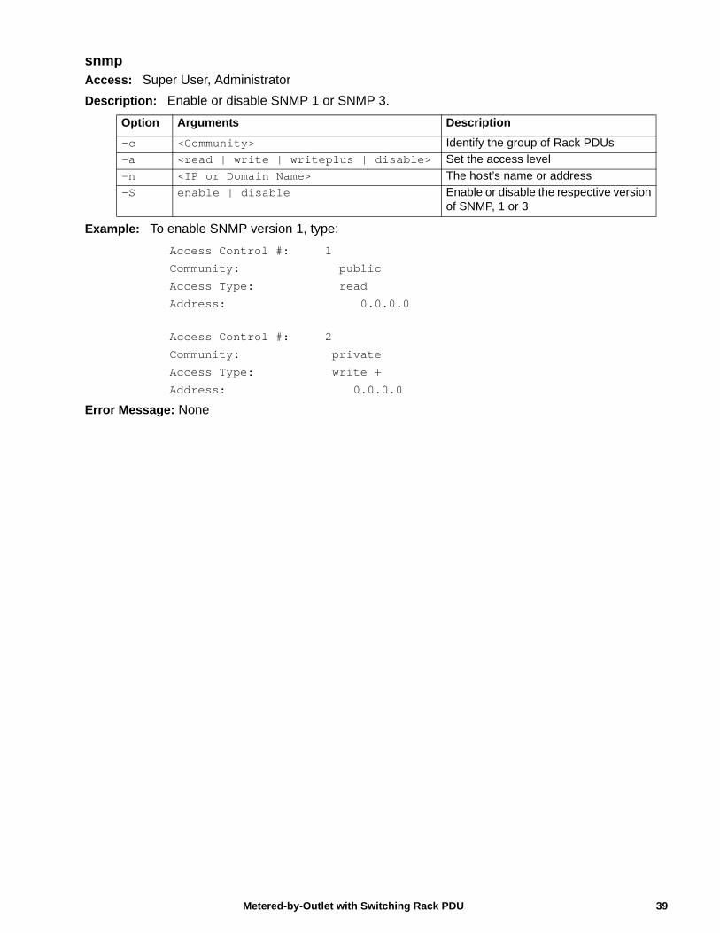
snmpAccess: Super User, Administrator
Description: Enable or disable SNMP 1 or SNMP 3.
Example: To enable SNMP version 1, type:
Access Control #: 1
Community: public
Access Type: read
Address: 0.0.0.0
Access Control #: 2
Community: private
Access Type: write +
Address: 0.0.0.0
Error Message: None
Option Arguments Description
-c <Community> Identify the group of Rack PDUs
-a <read | write | writeplus | disable> Set the access level
-n <IP or Domain Name> The host’s name or address
-S enable | disable Enable or disable the respective version of SNMP, 1 or 3
39Metered-by-Outlet with Switching Rack PDU
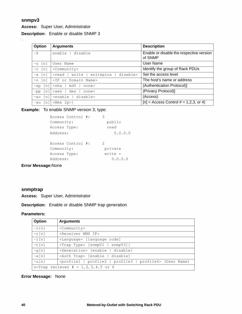
snmpv3Access: Super User, Administrator
Description: Enable or disable SNMP 3.
Example: To enable SNMP version 3, type:
Access Control #: 3Community: publicAccess Type: read
Address: 0.0.0.0
Access Control #: 2Community: privateAccess Type: write +Address: 0.0.0.0
Error Message:None
snmptrapAccess: Super User, Administrator
Description: Enable or disable SNMP trap generation
Parameters:
Error Message: None
Option Arguments Description
-S enable | disable Enable or disable the respective version of SNMP
-u [n] User Name User Name
-c [n] <Community> Identify the group of Rack PDUs
-a [n] <read | write | writeplus | disable> Set the access level
-n [n] <IP or Domain Name> The host’s name or address
-ap [n] <sha | md5 | none> (Authentication Protocol)]
-pp [n] <aes | des | none> (Privacy Protocol)]
-ac [n] <enable | disable> (Access)
-au [n] <Nms Ip>] [n] = Access Control # = 1,2,3, or 4)
Option Arguments
-c{n} <Community>-r[n] <Receiver NMS IP>-l[n] <Language> [language code]-t[n] <Trap Type> [snmpV1 | snmpV3]]-g[n] <Generation> [enable | disable]-a[n] <Auth Trap> [enable | disable]-u[n] <profile1 | profile2 | profile3 | profile4> (User Name)n=Trap reciever # = 1,2,3,4,5 or 6
Metered-by-Outlet with Switching Rack PDU40
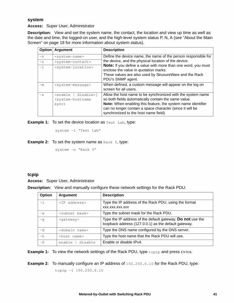
41Metered-by-Outlet with Switching Rack PDU
systemAccess: Super User, Administrator
Description: View and set the system name, the contact, the location and view up time as well as the date and time, the logged-on user, and the high-level system status P, N, A (see “About the Main Screen” on page 18 for more information about system status).
Example 1: To set the device location as Test Lab, type:
system -l “Test Lab”
Example 2: To set the system name as Rack 5, type:
system -n “Rack 5”
tcpipAccess: Super User, Administrator
Description: View and manually configure these network settings for the Rack PDU:
Example 1: To view the network settings of the Rack PDU, type tcpip and press ENTER.
Example 2: To manually configure an IP address of 150.250.6.10 for the Rack PDU, type:
tcpip -i 150.250.6.10
Option Argument Description
-n <system-name> Define the device name, the name of the person responsible for the device, and the physical location of the device. Note: If you define a value with more than one word, you must enclose the value in quotation marks.These values are also used by StruxureWare and the Rack PDU’s SNMP agent.
-c <system-contact>-l <system-location>
-m <system-message> When defined, a custom message will appear on the log on screen for all users.
-s <enable | disable>] (system-hostname sync)
Allow the host name to be synchronized with the system name so both fields automatically contain the same value. Note: When enabling this feature, the system name identifier can no longer contain a space character (since it will be synchronized to the host name field).
Option Argument Description
-i <IP address> Type the IP address of the Rack PDU, using the format xxx.xxx.xxx.xxx
-s <subnet mask> Type the subnet mask for the Rack PDU.
-g <gateway> Type the IP address of the default gateway. Do not use the loopback address (127.0.0.1) as the default gateway.
-d <domain name> Type the DNS name configured by the DNS server.
-h <host name> Type the host name that the Rack PDU will use.
-S enable | disable Enable or disable IPv4.
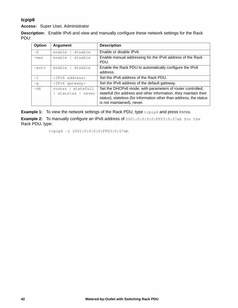
tcpip6Access: Super User, Administrator
Description: Enable IPv6 and view and manually configure these network settings for the Rack PDU:
Example 1: To view the network settings of the Rack PDU, type tcpip6 and press ENTER.
Example 2: To manually configure an IPv6 address of 2001:0:0:0:0:FFD3:0:57ab for the Rack PDU, type:
tcpip6 -i 2001:0:0:0:0:FFD3:0:57ab
Option Argument Description
-S enable | disable Enable or disable IPv6.
-man enable | disable Enable manual addressing for the IPv6 address of the Rack PDU.
-auto enable | disable Enable the Rack PDU to automatically configure the IPv6 address.
-i <IPv6 address> Set the IPv6 address of the Rack PDU.
-g <IPv6 gateway> Set the IPv6 address of the default gateway.
-d6 router | statefull | statelss | never
Set the DHCPv6 mode, with parameters of router controlled, statefull (for address and other information, they maintain their status), stateless (for information other than address, the status is not maintained), never.
Metered-by-Outlet with Switching Rack PDU42
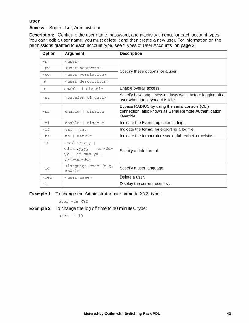
userAccess: Super User, Administrator
Description: Configure the user name, password, and inactivity timeout for each account types. You can’t edit a user name, you must delete it and then create a new user. For information on the permissions granted to each account type, see “Types of User Accounts” on page 2.
Example 1: To change the Administrator user name to XYZ, type:
user -an XYZ
Example 2: To change the log off time to 10 minutes, type:
user -t 10
Option Argument Description
-n <user>
Specify these options for a user.-pw <user password>
-pe <user permission>
-d <user description>
-e enable | disable Enable overall access.
-st <session timeout>Specify how long a session lasts waits before logging off a user when the keyboard is idle.
-sr enable | disableBypass RADIUS by using the serial console (CLI) connection, also known as Serial Remote Authentication Override
-el enable | disable Indicate the Event Log color coding.
-lf tab | csv Indicate the format for exporting a log file.
-ts us | metric Indicate the temperature scale, fahrenheit or celsius.
-df <mm/dd/yyyy | dd.mm.yyyy | mmm-dd-yy | dd-mmm-yy | yyyy-mm-dd>
Specify a date format.
-lg <language code (e.g. enUs)>
Specify a user language.
-del <user name> Delete a user.
-l Display the current user list.
43Metered-by-Outlet with Switching Rack PDU
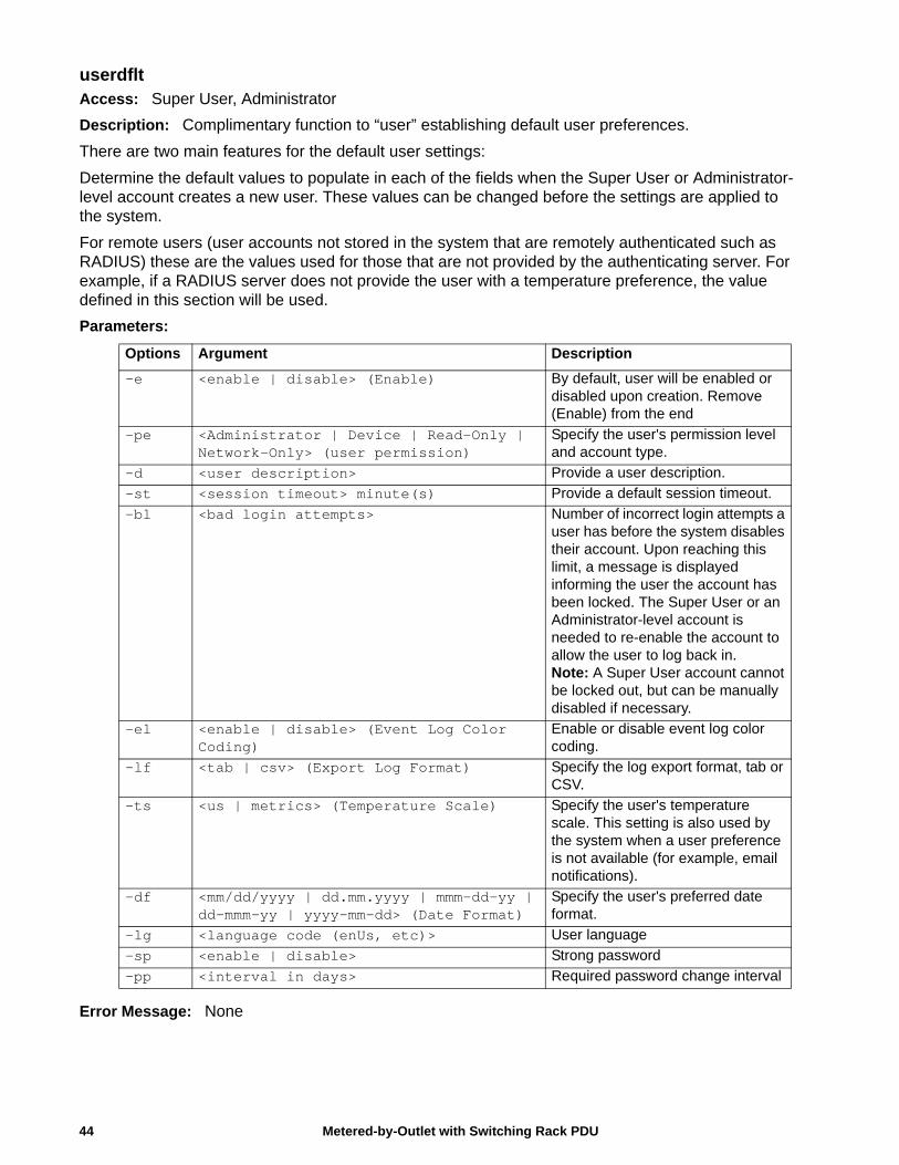
Metered-by-Outlet with Switching Rack PDU44
userdfltAccess: Super User, Administrator
Description: Complimentary function to “user” establishing default user preferences.
There are two main features for the default user settings:
Determine the default values to populate in each of the fields when the Super User or Administrator-level account creates a new user. These values can be changed before the settings are applied to the system.
For remote users (user accounts not stored in the system that are remotely authenticated such as RADIUS) these are the values used for those that are not provided by the authenticating server. For example, if a RADIUS server does not provide the user with a temperature preference, the value defined in this section will be used.
Parameters:
Error Message: None
Options Argument Description
-e <enable | disable> (Enable) By default, user will be enabled or disabled upon creation. Remove (Enable) from the end
-pe <Administrator | Device | Read-Only | Network-Only> (user permission)
Specify the user's permission level and account type.
-d <user description> Provide a user description.
-st <session timeout> minute(s) Provide a default session timeout.
-bl <bad login attempts> Number of incorrect login attempts a user has before the system disables their account. Upon reaching this limit, a message is displayed informing the user the account has been locked. The Super User or an Administrator-level account is needed to re-enable the account to allow the user to log back in. Note: A Super User account cannot be locked out, but can be manually disabled if necessary.
-el <enable | disable> (Event Log Color Coding)
Enable or disable event log color coding.
-lf <tab | csv> (Export Log Format) Specify the log export format, tab or CSV.
-ts <us | metrics> (Temperature Scale) Specify the user's temperature scale. This setting is also used by the system when a user preference is not available (for example, email notifications).
-df <mm/dd/yyyy | dd.mm.yyyy | mmm-dd-yy | dd-mmm-yy | yyyy-mm-dd> (Date Format)
Specify the user's preferred date format.
-lg <language code (enUs, etc)> User language
-sp <enable | disable> Strong password
-pp <interval in days> Required password change interval
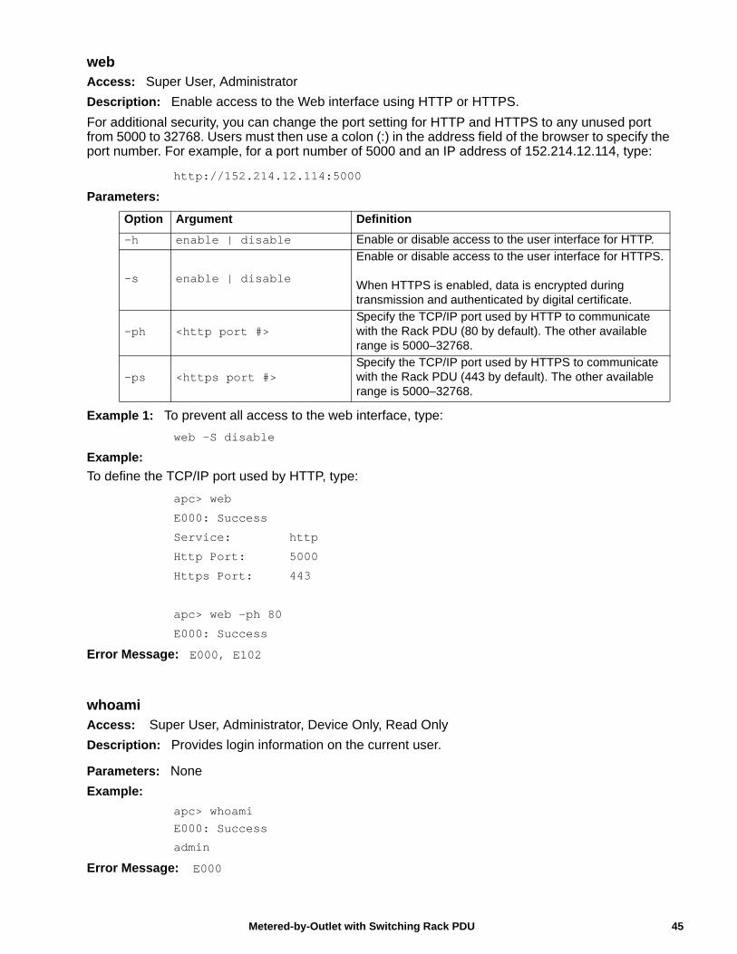
webAccess: Super User, Administrator
Description: Enable access to the Web interface using HTTP or HTTPS.
For additional security, you can change the port setting for HTTP and HTTPS to any unused port from 5000 to 32768. Users must then use a colon (:) in the address field of the browser to specify the port number. For example, for a port number of 5000 and an IP address of 152.214.12.114, type:
http://152.214.12.114:5000
Parameters:
Example 1: To prevent all access to the web interface, type:
web -S disable
Example:
To define the TCP/IP port used by HTTP, type:
apc> web
E000: Success
Service: http
Http Port: 5000
Https Port: 443
apc> web -ph 80
E000: Success
Error Message: E000, E102
whoamiAccess: Super User, Administrator, Device Only, Read Only
Description: Provides login information on the current user.
Parameters: None
Example:
apc> whoami
E000: Success
admin
Error Message: E000
Option Argument Definition
-h enable | disable Enable or disable access to the user interface for HTTP.
-s enable | disable
Enable or disable access to the user interface for HTTPS.
When HTTPS is enabled, data is encrypted during transmission and authenticated by digital certificate.
-ph <http port #>Specify the TCP/IP port used by HTTP to communicate with the Rack PDU (80 by default). The other available range is 5000–32768.
-ps <https port #>Specify the TCP/IP port used by HTTPS to communicate with the Rack PDU (443 by default). The other available range is 5000–32768.
45Metered-by-Outlet with Switching Rack PDU
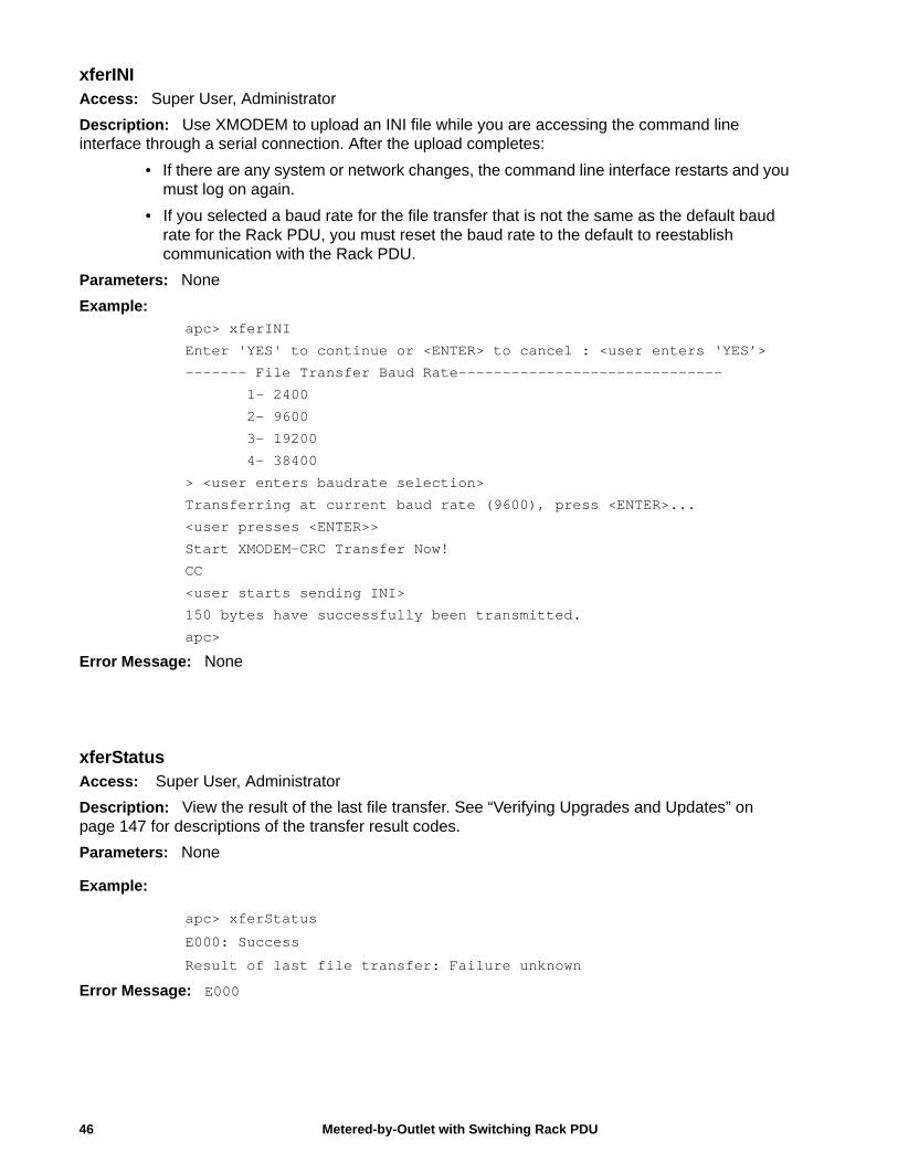
xferINIAccess: Super User, Administrator
Description: Use XMODEM to upload an INI file while you are accessing the command line interface through a serial connection. After the upload completes:
• If there are any system or network changes, the command line interface restarts and you must log on again.
• If you selected a baud rate for the file transfer that is not the same as the default baud rate for the Rack PDU, you must reset the baud rate to the default to reestablish communication with the Rack PDU.
Parameters: None
Example:
apc> xferINI
Enter 'YES' to continue or <ENTER> to cancel : <user enters ‘YES’>
------- File Transfer Baud Rate------------------------------
1- 2400
2- 9600
3- 19200
4- 38400
> <user enters baudrate selection>
Transferring at current baud rate (9600), press <ENTER>...
<user presses <ENTER>>
Start XMODEM-CRC Transfer Now!
CC
<user starts sending INI>
150 bytes have successfully been transmitted.
apc>
Error Message: None
xferStatusAccess: Super User, Administrator
Description: View the result of the last file transfer. See “Verifying Upgrades and Updates” on page 147 for descriptions of the transfer result codes.
Parameters: None
Example:
apc> xferStatus
E000: Success
Result of last file transfer: Failure unknown
Error Message: E000
Metered-by-Outlet with Switching Rack PDU46
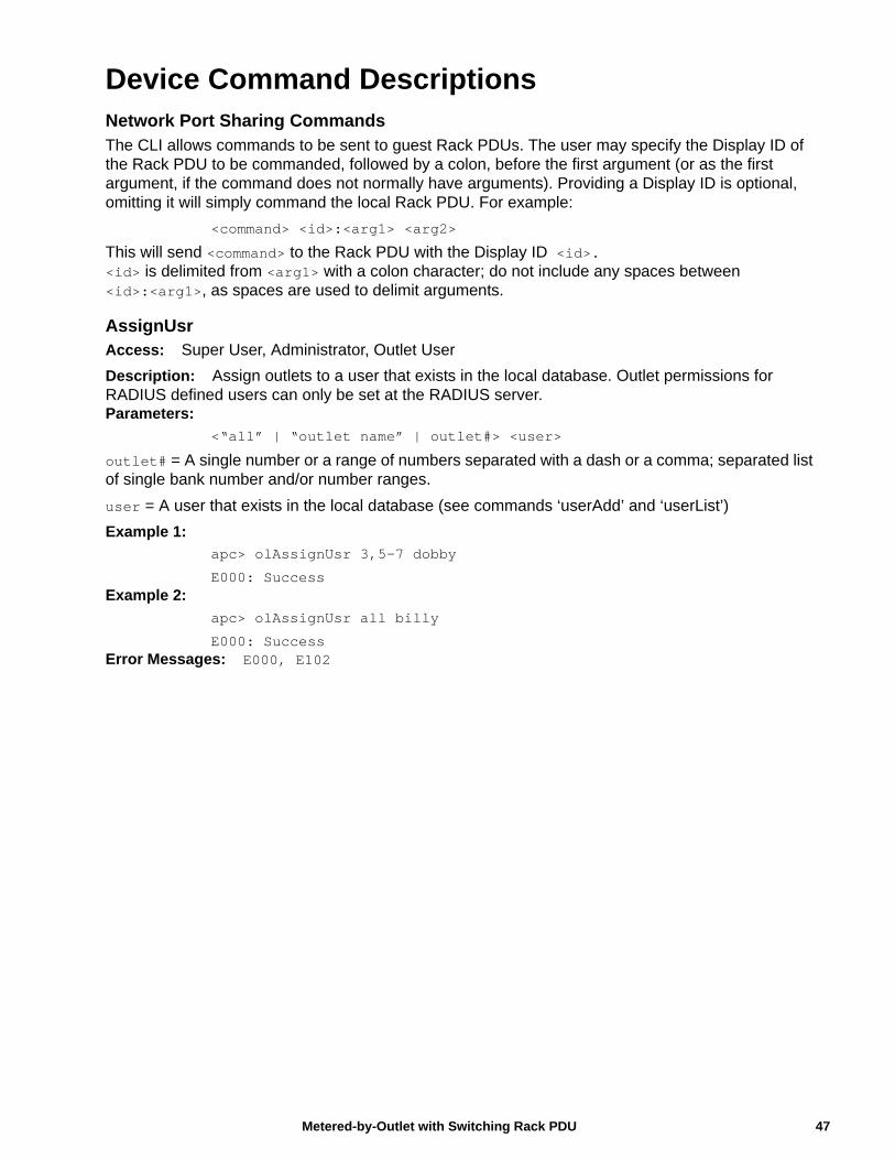
Device Command DescriptionsNetwork Port Sharing CommandsThe CLI allows commands to be sent to guest Rack PDUs. The user may specify the Display ID of the Rack PDU to be commanded, followed by a colon, before the first argument (or as the first argument, if the command does not normally have arguments). Providing a Display ID is optional, omitting it will simply command the local Rack PDU. For example:
<command> <id>:<arg1> <arg2>
This will send <command> to the Rack PDU with the Display ID <id>.<id> is delimited from <arg1> with a colon character; do not include any spaces between <id>:<arg1>, as spaces are used to delimit arguments.
AssignUsrAccess: Super User, Administrator, Outlet User
Description: Assign outlets to a user that exists in the local database. Outlet permissions for RADIUS defined users can only be set at the RADIUS server.Parameters:
<“all” | “outlet name” | outlet#> <user>
outlet# = A single number or a range of numbers separated with a dash or a comma; separated list of single bank number and/or number ranges.
user = A user that exists in the local database (see commands ‘userAdd’ and ‘userList’)
Example 1:
apc> olAssignUsr 3,5-7 dobby
E000: SuccessExample 2:
apc> olAssignUsr all billy
E000: SuccessError Messages: E000, E102
47Metered-by-Outlet with Switching Rack PDU

bkLowLoadAccess: Super User, Administrator, Device User
Description: Set or view the bank low-load threshold current in amps. You can specify all banks, a single bank, a range, or a comma-separated list of single banks and/or ranges.Parameters:
[id#:]<all | bank#> [current]
bank# = A single number or a range of numbers separated with a dash or a comma; separated list of single bank number and/or number ranges.current = The new bank threshold (Amps)
Example 1: To set the low-load threshold for all banks to 1A, type:apc> bkLowLoad all 1E000: Success
Example 2: To view the low-load threshold setting for banks 1 through 3, type:apc> bkLowLoad 1-3E000: Success1: 1 A2: 1 A3: 1 A
Error Messages: E000, E102
Metered-by-Outlet with Switching Rack PDU48
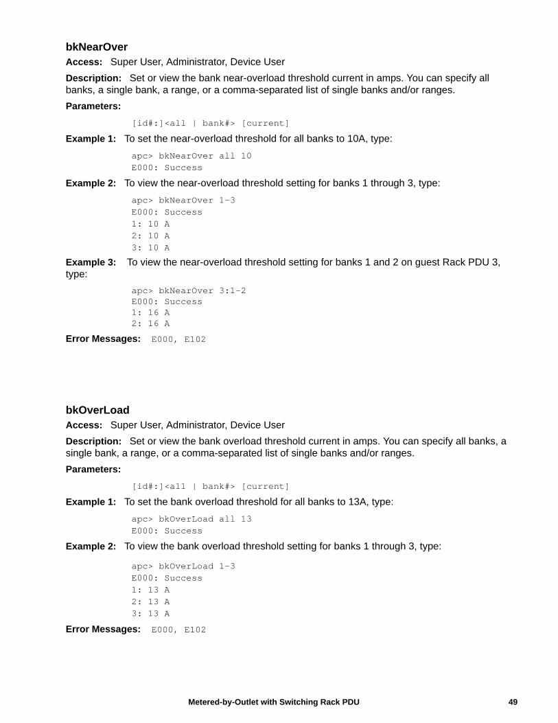
bkNearOverAccess: Super User, Administrator, Device User
Description: Set or view the bank near-overload threshold current in amps. You can specify all banks, a single bank, a range, or a comma-separated list of single banks and/or ranges.
Parameters:
[id#:]<all | bank#> [current]
Example 1: To set the near-overload threshold for all banks to 10A, type:
apc> bkNearOver all 10E000: Success
Example 2: To view the near-overload threshold setting for banks 1 through 3, type:
apc> bkNearOver 1-3E000: Success1: 10 A2: 10 A3: 10 A
Example 3: To view the near-overload threshold setting for banks 1 and 2 on guest Rack PDU 3, type:
apc> bkNearOver 3:1-2E000: Success1: 16 A2: 16 A
Error Messages: E000, E102
bkOverLoadAccess: Super User, Administrator, Device User
Description: Set or view the bank overload threshold current in amps. You can specify all banks, a single bank, a range, or a comma-separated list of single banks and/or ranges.
Parameters:
[id#:]<all | bank#> [current]
Example 1: To set the bank overload threshold for all banks to 13A, type:
apc> bkOverLoad all 13E000: Success
Example 2: To view the bank overload threshold setting for banks 1 through 3, type:
apc> bkOverLoad 1-3E000: Success1: 13 A2: 13 A3: 13 A
Error Messages: E000, E102
49Metered-by-Outlet with Switching Rack PDU
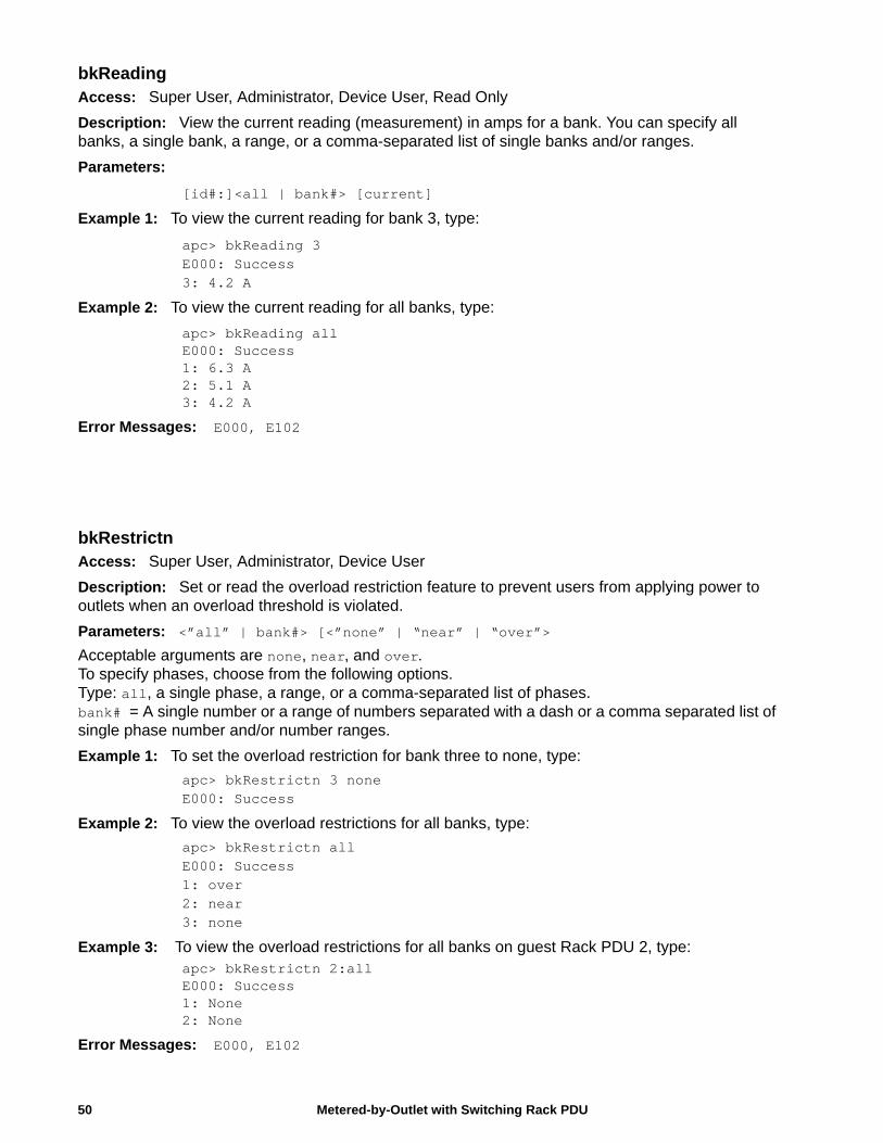
Metered-by-Outlet with Switching Rack PDU50
bkReadingAccess: Super User, Administrator, Device User, Read Only
Description: View the current reading (measurement) in amps for a bank. You can specify all banks, a single bank, a range, or a comma-separated list of single banks and/or ranges.
Parameters:
[id#:]<all | bank#> [current]
Example 1: To view the current reading for bank 3, type:
apc> bkReading 3E000: Success3: 4.2 A
Example 2: To view the current reading for all banks, type:
apc> bkReading allE000: Success1: 6.3 A2: 5.1 A3: 4.2 A
Error Messages: E000, E102
bkRestrictnAccess: Super User, Administrator, Device User
Description: Set or read the overload restriction feature to prevent users from applying power to outlets when an overload threshold is violated.
Parameters: <”all” | bank#> [<”none” | “near” | “over”>
Acceptable arguments are none, near, and over. To specify phases, choose from the following options. Type: all, a single phase, a range, or a comma-separated list of phases.bank# = A single number or a range of numbers separated with a dash or a comma separated list of single phase number and/or number ranges.
Example 1: To set the overload restriction for bank three to none, type:
apc> bkRestrictn 3 noneE000: Success
Example 2: To view the overload restrictions for all banks, type:
apc> bkRestrictn allE000: Success1: over2: near3: none
Example 3: To view the overload restrictions for all banks on guest Rack PDU 2, type:apc> bkRestrictn 2:allE000: Success1: None2: None
Error Messages: E000, E102
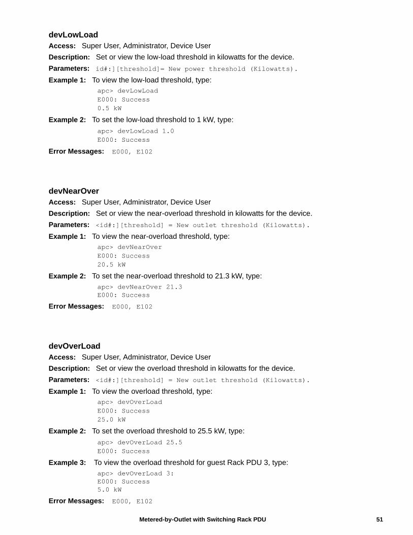
devLowLoadAccess: Super User, Administrator, Device User
Description: Set or view the low-load threshold in kilowatts for the device.
Parameters: id#:][threshold]= New power threshold (Kilowatts).
Example 1: To view the low-load threshold, type:apc> devLowLoadE000: Success0.5 kW
Example 2: To set the low-load threshold to 1 kW, type:
apc> devLowLoad 1.0E000: Success
Error Messages: E000, E102
devNearOverAccess: Super User, Administrator, Device User
Description: Set or view the near-overload threshold in kilowatts for the device.
Parameters: <id#:][threshold] = New outlet threshold (Kilowatts).
Example 1: To view the near-overload threshold, type:apc> devNearOverE000: Success20.5 kW
Example 2: To set the near-overload threshold to 21.3 kW, type:
apc> devNearOver 21.3E000: Success
Error Messages: E000, E102
devOverLoadAccess: Super User, Administrator, Device User
Description: Set or view the overload threshold in kilowatts for the device.
Parameters: <id#:][threshold] = New outlet threshold (Kilowatts).
Example 1: To view the overload threshold, type:apc> devOverLoadE000: Success25.0 kW
Example 2: To set the overload threshold to 25.5 kW, type:
apc> devOverLoad 25.5E000: Success
Example 3: To view the overload threshold for guest Rack PDU 3, type:apc> devOverLoad 3:E000: Success5.0 kW
Error Messages: E000, E102
51Metered-by-Outlet with Switching Rack PDU
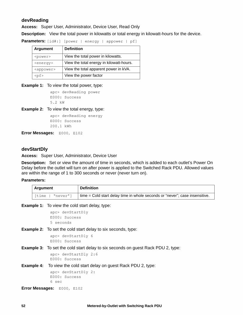
devReadingAccess: Super User, Administrator, Device User, Read Only
Description: View the total power in kilowatts or total energy in kilowatt-hours for the device.
Parameters: [id#:] [power | energy | appower | pf]
Example 1: To view the total power, type:
apc> devReading powerE000: Success5.2 kW
Example 2: To view the total energy, type:
apc> devReading energyE000: Success200.1 kWh
Error Messages: E000, E102
devStartDlyAccess: Super User, Administrator, Device User
Description: Set or view the amount of time in seconds, which is added to each outlet’s Power On Delay before the outlet will turn on after power is applied to the Switched Rack PDU. Allowed values are within the range of 1 to 300 seconds or never (never turn on).
Parameters:
Example 1: To view the cold start delay, type:
apc> devStartDlyE000: Success5 seconds
Example 2: To set the cold start delay to six seconds, type:
apc> devStartDly 6E000: Success
Example 3: To set the cold start delay to six seconds on guest Rack PDU 2, type:apc> devStartDly 2:6E000: Success
Example 4: To view the cold start delay on guest Rack PDU 2, type:
apc> devStartDly 2:E000: Success6 sec
Error Messages: E000, E102
Argument Definition
<power> View the total power in kilowatts.
<energy> View the total energy in kilowatt-hours.
<appower> View the total apparent power in kVA.
<pf> View the power factor
Argument Definition
[time | “never”] time = Cold start delay time in whole seconds or “never”; case insensitive.
Metered-by-Outlet with Switching Rack PDU52
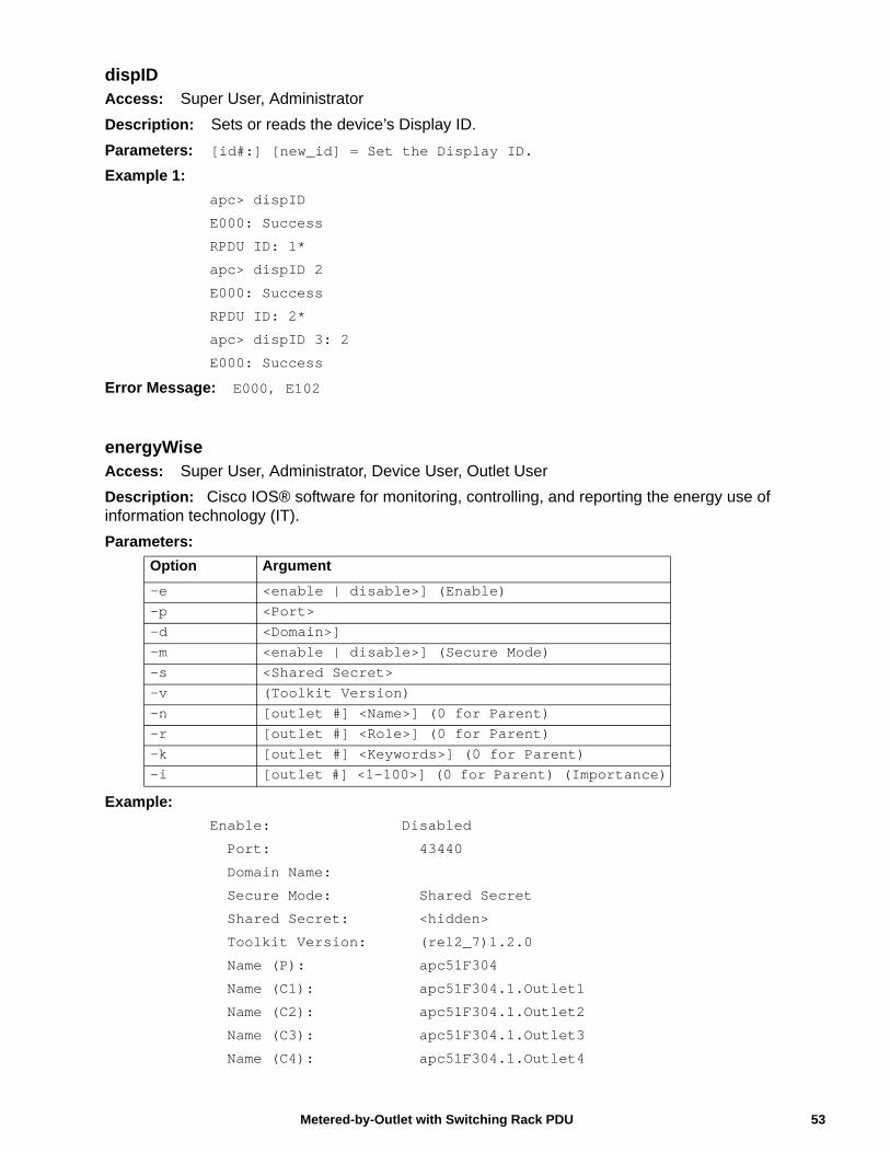
dispIDAccess: Super User, Administrator
Description: Sets or reads the device’s Display ID.
Parameters: [id#:] [new_id] = Set the Display ID.
Example 1:
apc> dispID
E000: Success
RPDU ID: 1*
apc> dispID 2
E000: Success
RPDU ID: 2*
apc> dispID 3: 2
E000: Success
Error Message: E000, E102
energyWiseAccess: Super User, Administrator, Device User, Outlet User
Description: Cisco IOS® software for monitoring, controlling, and reporting the energy use of information technology (IT).
Parameters:
Example:
Enable: Disabled
Port: 43440
Domain Name:
Secure Mode: Shared Secret
Shared Secret: <hidden>
Toolkit Version: (rel2_7)1.2.0
Name (P): apc51F304
Name (C1): apc51F304.1.Outlet1
Name (C2): apc51F304.1.Outlet2
Name (C3): apc51F304.1.Outlet3
Name (C4): apc51F304.1.Outlet4
Option Argument
-e <enable | disable>] (Enable)-p <Port>-d <Domain>]-m <enable | disable>] (Secure Mode)-s <Shared Secret>-v (Toolkit Version)-n [outlet #] <Name>] (0 for Parent)-r [outlet #] <Role>] (0 for Parent)-k [outlet #] <Keywords>] (0 for Parent)-i [outlet #] <1-100>] (0 for Parent) (Importance)
53Metered-by-Outlet with Switching Rack PDU
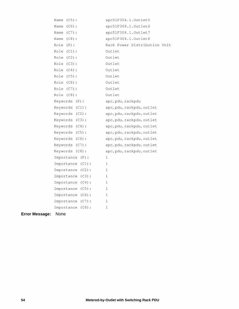
Name (C5): apc51F304.1.Outlet5
Name (C6): apc51F304.1.Outlet6
Name (C7): apc51F304.1.Outlet7
Name (C8): apc51F304.1.Outlet8
Role (P): Rack Power Distribution Unit
Role (C1): Outlet
Role (C2): Outlet
Role (C3): Outlet
Role (C4): Outlet
Role (C5): Outlet
Role (C6): Outlet
Role (C7): Outlet
Role (C8): Outlet
Keywords (P): apc,pdu,rackpdu
Keywords (C1): apc,pdu,rackpdu,outlet
Keywords (C2): apc,pdu,rackpdu,outlet
Keywords (C3): apc,pdu,rackpdu,outlet
Keywords (C4): apc,pdu,rackpdu,outlet
Keywords (C5): apc,pdu,rackpdu,outlet
Keywords (C6): apc,pdu,rackpdu,outlet
Keywords (C7): apc,pdu,rackpdu,outlet
Keywords (C8): apc,pdu,rackpdu,outlet
Importance (P): 1
Importance (C1): 1
Importance (C2): 1
Importance (C3): 1
Importance (C4): 1
Importance (C5): 1
Importance (C6): 1
Importance (C7): 1
Importance (C8): 1
Error Message: None
Metered-by-Outlet with Switching Rack PDU54
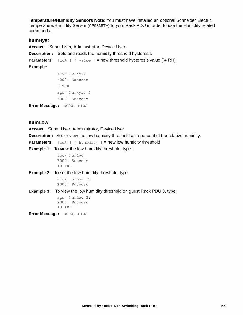
Temperature/Humidity Sensors Note: You must have installed an optional Schneider Electric Temperature/Humidity Sensor (AP9335TH) to your Rack PDU in order to use the Humidity related commands.
humHystAccess: Super User, Administrator, Device User
Description: Sets and reads the humidity threshold hysteresis
Parameters: [id#:] [ value ] = new threshold hysteresis value (% RH)
Example:
apc> humHyst
E000: Success
6 %RH
apc> humHyst 5
E000: Success
Error Message: E000, E102
humLowAccess: Super User, Administrator, Device User
Description: Set or view the low humidity threshold as a percent of the relative humidity.
Parameters: [id#:] [ humidity ] = new low humidity threshold
Example 1: To view the low humidity threshold, type:
apc> humLowE000: Success10 %RH
Example 2: To set the low humidity threshold, type:
apc> humLow 12E000: Success
Example 3: To view the low humidity threshold on guest Rack PDU 3, type:apc> humLow 3:E000: Success10 %RH
Error Message: E000, E102
55Metered-by-Outlet with Switching Rack PDU
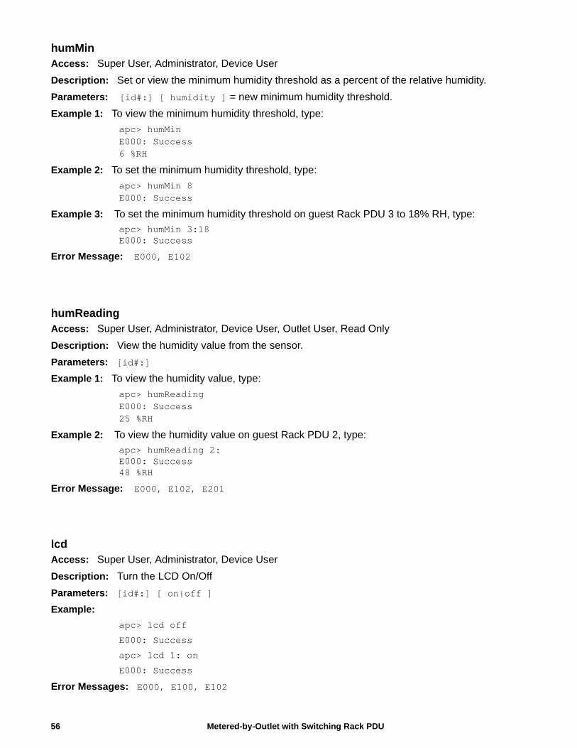
humMinAccess: Super User, Administrator, Device User
Description: Set or view the minimum humidity threshold as a percent of the relative humidity.
Parameters: [id#:] [ humidity ] = new minimum humidity threshold.
Example 1: To view the minimum humidity threshold, type:
apc> humMinE000: Success6 %RH
Example 2: To set the minimum humidity threshold, type:
apc> humMin 8E000: Success
Example 3: To set the minimum humidity threshold on guest Rack PDU 3 to 18% RH, type:apc> humMin 3:18E000: Success
Error Message: E000, E102
humReadingAccess: Super User, Administrator, Device User, Outlet User, Read Only
Description: View the humidity value from the sensor.
Parameters: [id#:]
Example 1: To view the humidity value, type:
apc> humReadingE000: Success25 %RH
Example 2: To view the humidity value on guest Rack PDU 2, type:
apc> humReading 2:E000: Success48 %RH
Error Message: E000, E102, E201
lcdAccess: Super User, Administrator, Device User
Description: Turn the LCD On/Off
Parameters: [id#:] [ on|off ]
Example:
apc> lcd off
E000: Success
apc> lcd 1: on
E000: Success
Error Messages: E000, E100, E102
Metered-by-Outlet with Switching Rack PDU56
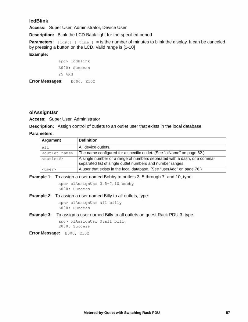
lcdBlinkAccess: Super User, Administrator, Device User
Description: Blink the LCD Back-light for the specified period
Parameters: [id#:] [ time ] = is the number of minutes to blink the display. It can be canceled by pressing a button on the LCD. Valid range is [1-10]
Example:
apc> lcdBlink
E000: Success
25 %RH
Error Messages: E000, E102
olAssignUsrAccess: Super User, Administrator
Description: Assign control of outlets to an outlet user that exists in the local database.
Parameters:
Example 1: To assign a user named Bobby to outlets 3, 5 through 7, and 10, type:
apc> olAssignUsr 3,5-7,10 bobbyE000: Success
Example 2: To assign a user named Billy to all outlets, type:
apc> olAssignUsr all billyE000: Success
Example 3: To assign a user named Billy to all outlets on guest Rack PDU 3, type:
apc> olAssignUsr 3:all billyE000: Success
Error Message: E000, E102
Argument Definition
all All device outlets.
<outlet name> The name configured for a specific outlet. (See “olName” on page 62.)
<outlet#> A single number or a range of numbers separated with a dash, or a comma-separated list of single outlet numbers and number ranges.
<user> A user that exists in the local database. (See “userAdd” on page 76.)
57Metered-by-Outlet with Switching Rack PDU
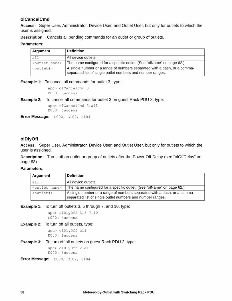
olCancelCmdAccess: Super User, Administrator, Device User, and Outlet User, but only for outlets to which the user is assigned.
Description: Cancels all pending commands for an outlet or group of outlets.
Parameters:
Example 1: To cancel all commands for outlet 3, type:
apc> olCancelCmd 3E000: Success
Example 2: To cancel all commands for outlet 3 on guest Rack PDU 3, type:apc> olCancelCmd 3:allE000: Success
Error Message: E000, E102, E104
olDlyOffAccess: Super User, Administrator, Device User, and Outlet User, but only for outlets to which the user is assigned.
Description: Turns off an outlet or group of outlets after the Power Off Delay (see “olOffDelay” on page 63).
Parameters:
Example 1: To turn off outlets 3, 5 through 7, and 10, type:
apc> olDlyOff 3,5-7,10E000: Success
Example 2: To turn off all outlets, type:
apc> olDlyOff allE000: Success
Example 3: To turn off all outlets on guest Rack PDU 2, type:apc> olDlyOff 2:allE000: Success
Error Message: E000, E102, E104
Argument Definition
all All device outlets.
<outlet name> The name configured for a specific outlet. (See “olName” on page 62.)
<outlet#> A single number or a range of numbers separated with a dash, or a comma-separated list of single outlet numbers and number ranges.
Argument Definition
all All device outlets.
<outlet name> The name configured for a specific outlet. (See “olName” on page 62.)
<outlet#> A single number or a range of numbers separated with a dash, or a comma-separated list of single outlet numbers and number ranges.
Metered-by-Outlet with Switching Rack PDU58
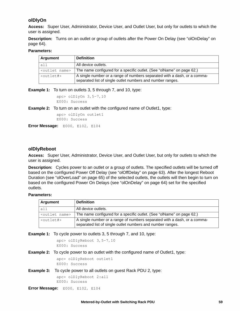
olDlyOnAccess: Super User, Administrator, Device User, and Outlet User, but only for outlets to which the user is assigned.
Description: Turns on an outlet or group of outlets after the Power On Delay (see “olOnDelay” on page 64).
Parameters:
Example 1: To turn on outlets 3, 5 through 7, and 10, type:
apc> olDlyOn 3,5-7,10E000: Success
Example 2: To turn on an outlet with the configured name of Outlet1, type:apc> olDlyOn outlet1E000: Success
Error Message: E000, E102, E104
olDlyRebootAccess: Super User, Administrator, Device User, and Outlet User, but only for outlets to which the user is assigned.
Description: Cycles power to an outlet or a group of outlets. The specified outlets will be turned off based on the configured Power Off Delay (see “olOffDelay” on page 63). After the longest Reboot Duration (see “olOverLoad” on page 65) of the selected outlets, the outlets will then begin to turn on based on the configured Power On Delays (see “olOnDelay” on page 64) set for the specified outlets.
Parameters:
Example 1: To cycle power to outlets 3, 5 through 7, and 10, type:
apc> olDlyReboot 3,5-7,10E000: Success
Example 2: To cycle power to an outlet with the configured name of Outlet1, type:
apc> olDlyReboot outlet1E000: Success
Example 3: To cycle power to all outlets on guest Rack PDU 2, type:apc> olDlyReboot 2:allE000: Success
Error Message: E000, E102, E104
Argument Definition
all All device outlets.
<outlet name> The name configured for a specific outlet. (See “olName” on page 62.)
<outlet#> A single number or a range of numbers separated with a dash, or a comma-separated list of single outlet numbers and number ranges.
Argument Definition
all All device outlets.
<outlet name> The name configured for a specific outlet. (See “olName” on page 62.)
<outlet#> A single number or a range of numbers separated with a dash, or a comma-separated list of single outlet numbers and number ranges.
59Metered-by-Outlet with Switching Rack PDU
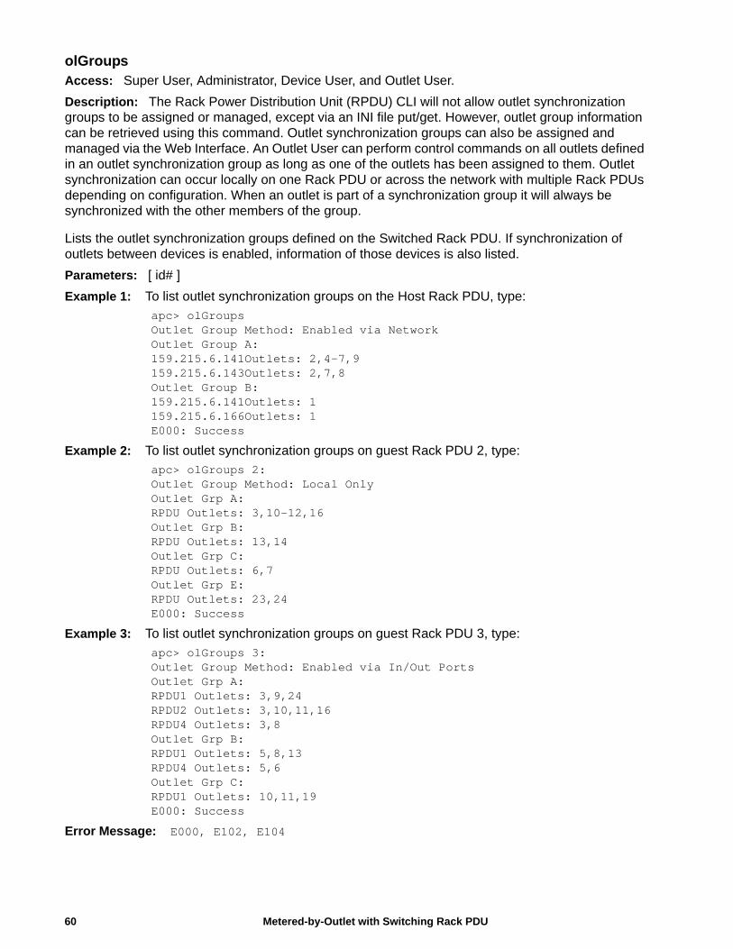
olGroupsAccess: Super User, Administrator, Device User, and Outlet User.
Description: The Rack Power Distribution Unit (RPDU) CLI will not allow outlet synchronization groups to be assigned or managed, except via an INI file put/get. However, outlet group information can be retrieved using this command. Outlet synchronization groups can also be assigned and managed via the Web Interface. An Outlet User can perform control commands on all outlets defined in an outlet synchronization group as long as one of the outlets has been assigned to them. Outlet synchronization can occur locally on one Rack PDU or across the network with multiple Rack PDUs depending on configuration. When an outlet is part of a synchronization group it will always be synchronized with the other members of the group.
Lists the outlet synchronization groups defined on the Switched Rack PDU. If synchronization of outlets between devices is enabled, information of those devices is also listed.
Parameters: [ id# ]
Example 1: To list outlet synchronization groups on the Host Rack PDU, type:
apc> olGroupsOutlet Group Method: Enabled via NetworkOutlet Group A: 159.215.6.141Outlets: 2,4-7,9159.215.6.143Outlets: 2,7,8Outlet Group B:159.215.6.141Outlets: 1159.215.6.166Outlets: 1E000: Success
Example 2: To list outlet synchronization groups on guest Rack PDU 2, type:apc> olGroups 2:Outlet Group Method: Local OnlyOutlet Grp A:RPDU Outlets: 3,10-12,16Outlet Grp B:RPDU Outlets: 13,14Outlet Grp C:RPDU Outlets: 6,7Outlet Grp E:RPDU Outlets: 23,24E000: Success
Example 3: To list outlet synchronization groups on guest Rack PDU 3, type:
apc> olGroups 3:Outlet Group Method: Enabled via In/Out PortsOutlet Grp A:RPDU1 Outlets: 3,9,24RPDU2 Outlets: 3,10,11,16RPDU4 Outlets: 3,8Outlet Grp B:RPDU1 Outlets: 5,8,13RPDU4 Outlets: 5,6Outlet Grp C:RPDU1 Outlets: 10,11,19E000: Success
Error Message: E000, E102, E104
Metered-by-Outlet with Switching Rack PDU60
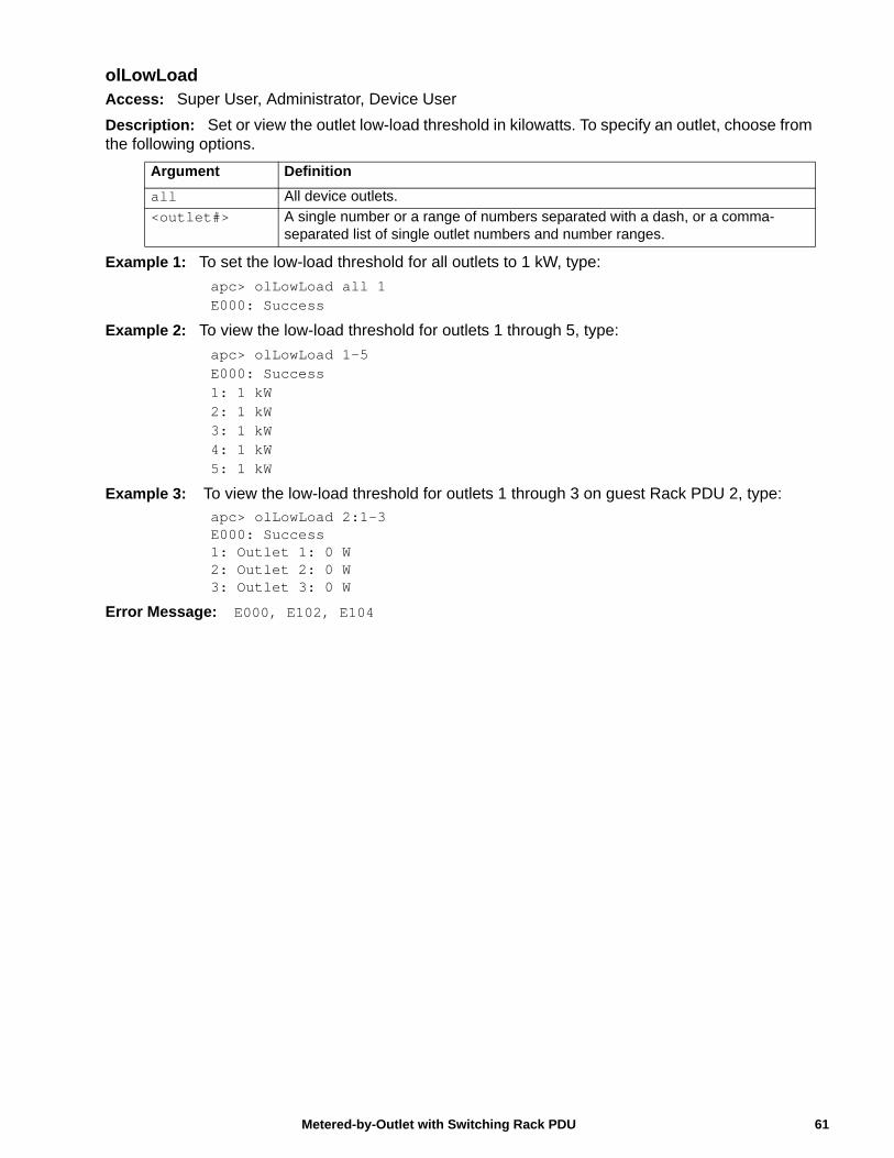
olLowLoadAccess: Super User, Administrator, Device User
Description: Set or view the outlet low-load threshold in kilowatts. To specify an outlet, choose from the following options.
Example 1: To set the low-load threshold for all outlets to 1 kW, type:
apc> olLowLoad all 1E000: Success
Example 2: To view the low-load threshold for outlets 1 through 5, type:
apc> olLowLoad 1-5E000: Success1: 1 kW2: 1 kW3: 1 kW4: 1 kW5: 1 kW
Example 3: To view the low-load threshold for outlets 1 through 3 on guest Rack PDU 2, type:
apc> olLowLoad 2:1-3E000: Success1: Outlet 1: 0 W2: Outlet 2: 0 W3: Outlet 3: 0 W
Error Message: E000, E102, E104
Argument Definition
all All device outlets.
<outlet#> A single number or a range of numbers separated with a dash, or a comma-separated list of single outlet numbers and number ranges.
61Metered-by-Outlet with Switching Rack PDU
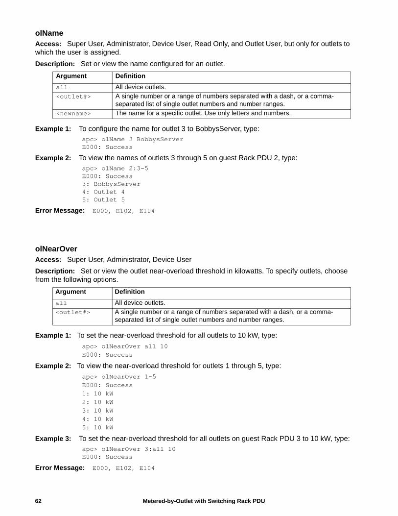
olNameAccess: Super User, Administrator, Device User, Read Only, and Outlet User, but only for outlets to which the user is assigned.
Description: Set or view the name configured for an outlet.
Example 1: To configure the name for outlet 3 to BobbysServer, type:
apc> olName 3 BobbysServerE000: Success
Example 2: To view the names of outlets 3 through 5 on guest Rack PDU 2, type:apc> olName 2:3-5E000: Success3: BobbysServer4: Outlet 45: Outlet 5
Error Message: E000, E102, E104
olNearOverAccess: Super User, Administrator, Device User
Description: Set or view the outlet near-overload threshold in kilowatts. To specify outlets, choose from the following options.
Example 1: To set the near-overload threshold for all outlets to 10 kW, type:
apc> olNearOver all 10E000: Success
Example 2: To view the near-overload threshold for outlets 1 through 5, type:
apc> olNearOver 1-5E000: Success1: 10 kW2: 10 kW3: 10 kW4: 10 kW5: 10 kW
Example 3: To set the near-overload threshold for all outlets on guest Rack PDU 3 to 10 kW, type:apc> olNearOver 3:all 10E000: Success
Error Message: E000, E102, E104
Argument Definition
all All device outlets.
<outlet#> A single number or a range of numbers separated with a dash, or a comma-separated list of single outlet numbers and number ranges.
<newname> The name for a specific outlet. Use only letters and numbers.
Argument Definition
all All device outlets.
<outlet#> A single number or a range of numbers separated with a dash, or a comma-separated list of single outlet numbers and number ranges.
Metered-by-Outlet with Switching Rack PDU62
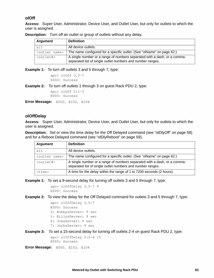
olOffAccess: Super User, Administrator, Device User, and Outlet User, but only for outlets to which the user is assigned.
Description: Turn off an outlet or group of outlets without any delay.
Example 1: To turn off outlets 3 and 5 through 7, type:
apc> olOff 3,5-7E000: Success
Example 2: To turn off outlets 1 through 3 on guest Rack PDU 2, type:apc> olOff 2:1-3E000: Success
Error Message: E000, E102, E104
olOffDelayAccess: Super User, Administrator, Device User, and Outlet User, but only for outlets to which the user is assigned.
Description: Set or view the time delay for the Off Delayed command (see “olDlyOff” on page 58) and for a Reboot Delayed command (see “olDlyReboot” on page 59).
Example 1: To set a 9-second delay for turning off outlets 3 and 5 through 7, type:
apc> olOffDelay 3,5-7 9E000: Success
Example 2: To view the delay for the Off Delayed command for outlets 3 and 5 through 7, type:
apc> olOffDelay 3,5-7E000: Success3: BobbysServer: 9 sec5: BillysServer: 9 sec6: JoesServer: 9 sec7: JacksServer: 9 sec
Example 3: To set a 15-second delay for turning off outlets 2-4 on guest Rack PDU 2, type:
apc> olOffDelay 2:2-4 15E000: Success
Error Message: E000, E102, E104
Argument Definition
all All device outlets.
<outlet name> The name configured for a specific outlet. (See “olName” on page 62.)
<outlet#> A single number or a range of numbers separated with a dash, or a comma-separated list of single outlet numbers and number ranges.
Argument Definition
all All device outlets.
<outlet name> The name configured for a specific outlet. (See “olName” on page 62.)
<outlet#> A single number or a range of numbers separated with a dash, or a comma-separated list of single outlet numbers and number ranges.
<time> A time for the delay within the range of 1 to 7200 seconds (2 hours).
63Metered-by-Outlet with Switching Rack PDU
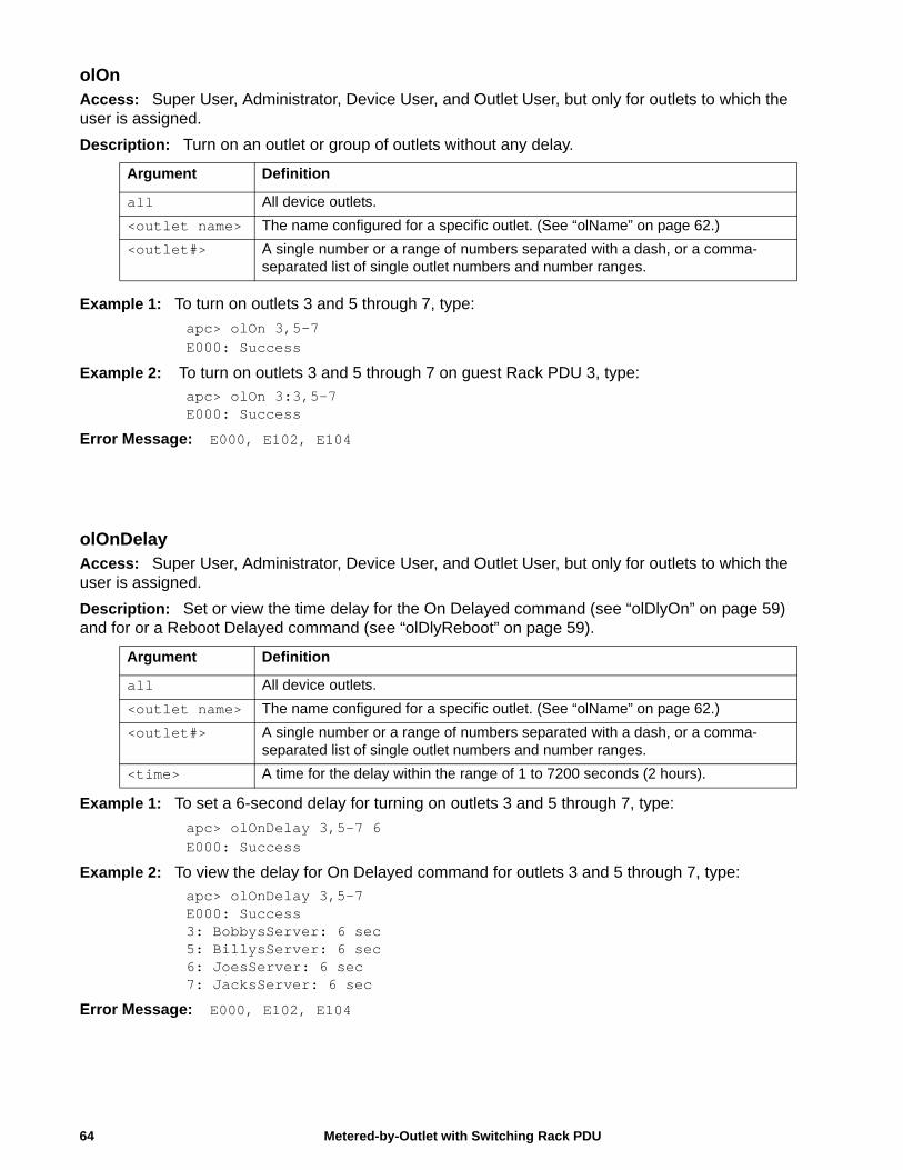
Metered-by-Outlet with Switching Rack PDU64
olOnAccess: Super User, Administrator, Device User, and Outlet User, but only for outlets to which the user is assigned.
Description: Turn on an outlet or group of outlets without any delay.
Example 1: To turn on outlets 3 and 5 through 7, type:
apc> olOn 3,5-7E000: Success
Example 2: To turn on outlets 3 and 5 through 7 on guest Rack PDU 3, type:apc> olOn 3:3,5-7E000: Success
Error Message: E000, E102, E104
olOnDelayAccess: Super User, Administrator, Device User, and Outlet User, but only for outlets to which the user is assigned.
Description: Set or view the time delay for the On Delayed command (see “olDlyOn” on page 59) and for or a Reboot Delayed command (see “olDlyReboot” on page 59).
Example 1: To set a 6-second delay for turning on outlets 3 and 5 through 7, type:
apc> olOnDelay 3,5-7 6E000: Success
Example 2: To view the delay for On Delayed command for outlets 3 and 5 through 7, type:
apc> olOnDelay 3,5-7E000: Success3: BobbysServer: 6 sec5: BillysServer: 6 sec6: JoesServer: 6 sec7: JacksServer: 6 sec
Error Message: E000, E102, E104
Argument Definition
all All device outlets.
<outlet name> The name configured for a specific outlet. (See “olName” on page 62.)
<outlet#> A single number or a range of numbers separated with a dash, or a comma-separated list of single outlet numbers and number ranges.
Argument Definition
all All device outlets.
<outlet name> The name configured for a specific outlet. (See “olName” on page 62.)
<outlet#> A single number or a range of numbers separated with a dash, or a comma-separated list of single outlet numbers and number ranges.
<time> A time for the delay within the range of 1 to 7200 seconds (2 hours).
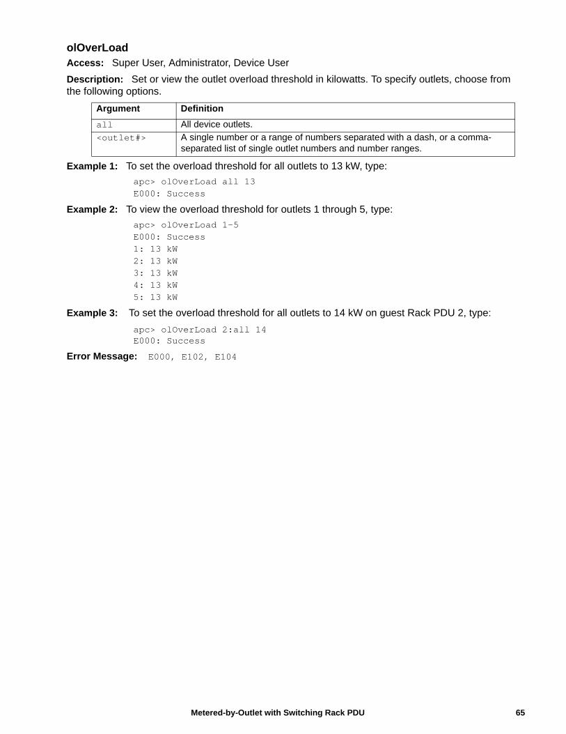
olOverLoadAccess: Super User, Administrator, Device User
Description: Set or view the outlet overload threshold in kilowatts. To specify outlets, choose from the following options.
Example 1: To set the overload threshold for all outlets to 13 kW, type:
apc> olOverLoad all 13E000: Success
Example 2: To view the overload threshold for outlets 1 through 5, type:
apc> olOverLoad 1-5E000: Success1: 13 kW2: 13 kW3: 13 kW4: 13 kW5: 13 kW
Example 3: To set the overload threshold for all outlets to 14 kW on guest Rack PDU 2, type:
apc> olOverLoad 2:all 14E000: Success
Error Message: E000, E102, E104
Argument Definition
all All device outlets.
<outlet#> A single number or a range of numbers separated with a dash, or a comma-separated list of single outlet numbers and number ranges.
65Metered-by-Outlet with Switching Rack PDU
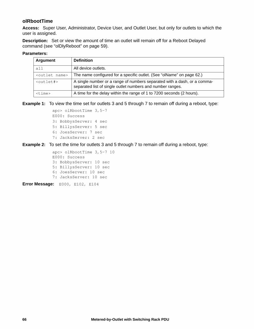
olRbootTimeAccess: Super User, Administrator, Device User, and Outlet User, but only for outlets to which the user is assigned.
Description: Set or view the amount of time an outlet will remain off for a Reboot Delayed command (see “olDlyReboot” on page 59).
Parameters:
Example 1: To view the time set for outlets 3 and 5 through 7 to remain off during a reboot, type:
apc> olRbootTime 3,5-7E000: Success3: BobbysServer: 4 sec5: BillysServer: 5 sec6: JoesServer: 7 sec7: JacksServer: 2 sec
Example 2: To set the time for outlets 3 and 5 through 7 to remain off during a reboot, type:
apc> olRbootTime 3,5-7 10E000: Success3: BobbysServer: 10 sec5: BillysServer: 10 sec6: JoesServer: 10 sec7: JacksServer: 10 sec
Error Message: E000, E102, E104
Argument Definition
all All device outlets.
<outlet name> The name configured for a specific outlet. (See “olName” on page 62.)
<outlet#> A single number or a range of numbers separated with a dash, or a comma-separated list of single outlet numbers and number ranges.
<time> A time for the delay within the range of 1 to 7200 seconds (2 hours).
Metered-by-Outlet with Switching Rack PDU66
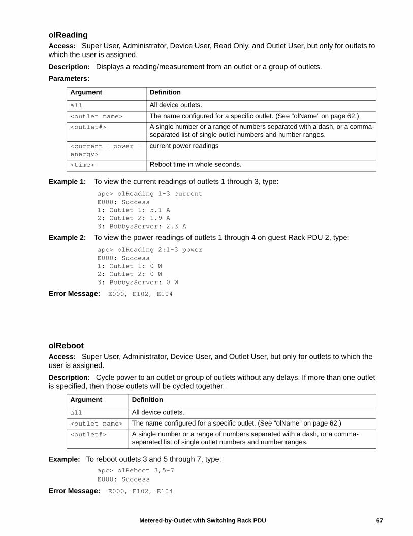
olReadingAccess: Super User, Administrator, Device User, Read Only, and Outlet User, but only for outlets to which the user is assigned.
Description: Displays a reading/measurement from an outlet or a group of outlets.
Parameters:
Example 1: To view the current readings of outlets 1 through 3, type:
apc> olReading 1-3 currentE000: Success1: Outlet 1: 5.1 A2: Outlet 2: 1.9 A3: BobbysServer: 2.3 A
Example 2: To view the power readings of outlets 1 through 4 on guest Rack PDU 2, type:
apc> olReading 2:1-3 powerE000: Success1: Outlet 1: 0 W2: Outlet 2: 0 W3: BobbysServer: 0 W
Error Message: E000, E102, E104
olRebootAccess: Super User, Administrator, Device User, and Outlet User, but only for outlets to which the user is assigned.
Description: Cycle power to an outlet or group of outlets without any delays. If more than one outlet is specified, then those outlets will be cycled together.
Example: To reboot outlets 3 and 5 through 7, type:
apc> olReboot 3,5-7E000: Success
Error Message: E000, E102, E104
Argument Definition
all All device outlets.
<outlet name> The name configured for a specific outlet. (See “olName” on page 62.)
<outlet#> A single number or a range of numbers separated with a dash, or a comma-separated list of single outlet numbers and number ranges.
<current | power | energy>
current power readings
<time> Reboot time in whole seconds.
Argument Definition
all All device outlets.
<outlet name> The name configured for a specific outlet. (See “olName” on page 62.)
<outlet#> A single number or a range of numbers separated with a dash, or a comma-separated list of single outlet numbers and number ranges.
67Metered-by-Outlet with Switching Rack PDU
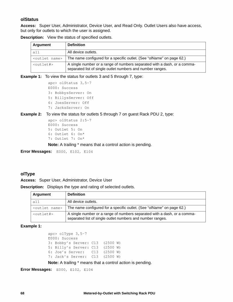
olStatusAccess: Super User, Administrator, Device User, and Read Only. Outlet Users also have access, but only for outlets to which the user is assigned.
Description: View the status of specified outlets.
Example 1: To view the status for outlets 3 and 5 through 7, type:
apc> olStatus 3,5-7E000: Success3: BobbysServer: On5: BillysServer: Off6: JoesServer: Off7: JacksServer: On
Example 2: To view the status for outlets 5 through 7 on guest Rack PDU 2, type:apc> olStatus 2:5-7E000: Success5: Outlet 5: On6: Outlet 6: On* 7: Outlet 7: On*
Note: A trailing * means that a control action is pending.
Error Messages: E000, E102, E104
olTypeAccess: Super User, Administrator, Device User
Description: Displays the type and rating of selected outlets.
Example 1:
apc> olType 3,5-7E000: Success3: Bobby’s Server: C13 (2500 W)5: Billy’s Server: C13 (2500 W)6: Joe’s Server: C13 (2500 W)7: Jack’s Server: C13 (2500 W)
Note: A trailing * means that a control action is pending.
Error Messages: E000, E102, E104
Argument Definition
all All device outlets.
<outlet name> The name configured for a specific outlet. (See “olName” on page 62.)
<outlet#> A single number or a range of numbers separated with a dash, or a comma-separated list of single outlet numbers and number ranges.
Argument Definition
all All device outlets.
<outlet name> The name configured for a specific outlet. (See “olName” on page 62.)
<outlet#> A single number or a range of numbers separated with a dash, or a comma-separated list of single outlet numbers and number ranges.
Metered-by-Outlet with Switching Rack PDU68
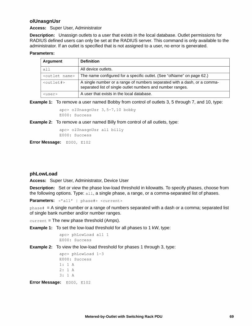
olUnasgnUsrAccess: Super User, Administrator
Description: Unassign outlets to a user that exists in the local database. Outlet permissions for RADIUS defined users can only be set at the RADIUS server. This command is only available to the administrator. If an outlet is specified that is not assigned to a user, no error is generated.
Parameters:
Example 1: To remove a user named Bobby from control of outlets 3, 5 through 7, and 10, type:
apc> olUnasgnUsr 3,5-7,10 bobbyE000: Success
Example 2: To remove a user named Billy from control of all outlets, type:
apc> olUnasgnUsr all billyE000: Success
Error Message: E000, E102
phLowLoadAccess: Super User, Administrator, Device User
Description: Set or view the phase low-load threshold in kilowatts. To specify phases, choose from the following options. Type: all, a single phase, a range, or a comma-separated list of phases.
Parameters: <”all” | phase#> <current>
phase# = A single number or a range of numbers separated with a dash or a comma; separated list of single bank number and/or number ranges.
current = The new phase threshold (Amps).
Example 1: To set the low-load threshold for all phases to 1 kW, type:
apc> phLowLoad all 1E000: Success
Example 2: To view the low-load threshold for phases 1 through 3, type:
apc> phLowLoad 1-3E000: Success1: 1 A2: 1 A3: 1 A
Error Message: E000, E102
Argument Definition
all All device outlets.
<outlet name> The name configured for a specific outlet. (See “olName” on page 62.)
<outlet#> A single number or a range of numbers separated with a dash, or a comma-separated list of single outlet numbers and number ranges.
<user> A user that exists in the local database.
69Metered-by-Outlet with Switching Rack PDU
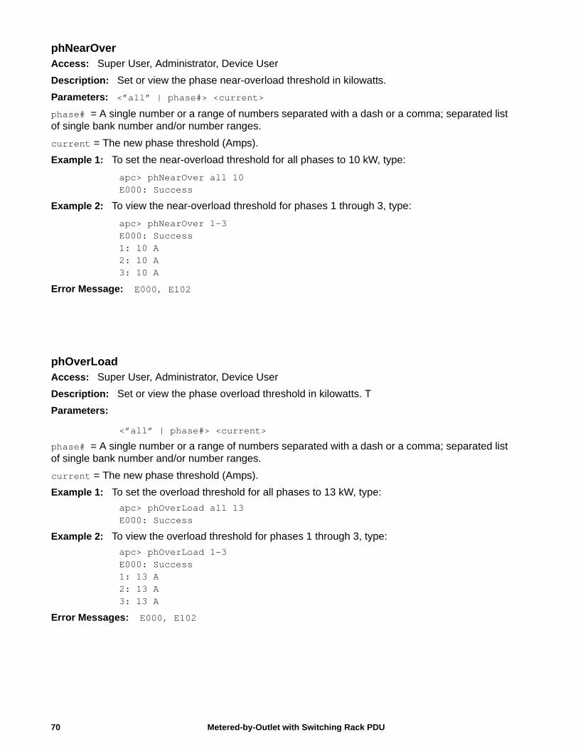
phNearOverAccess: Super User, Administrator, Device User
Description: Set or view the phase near-overload threshold in kilowatts.
Parameters: <”all” | phase#> <current>
phase# = A single number or a range of numbers separated with a dash or a comma; separated list of single bank number and/or number ranges.
current = The new phase threshold (Amps).
Example 1: To set the near-overload threshold for all phases to 10 kW, type:
apc> phNearOver all 10E000: Success
Example 2: To view the near-overload threshold for phases 1 through 3, type:
apc> phNearOver 1-3E000: Success1: 10 A2: 10 A3: 10 A
Error Message: E000, E102
phOverLoadAccess: Super User, Administrator, Device User
Description: Set or view the phase overload threshold in kilowatts. T
Parameters:
<”all” | phase#> <current>
phase# = A single number or a range of numbers separated with a dash or a comma; separated list of single bank number and/or number ranges.
current = The new phase threshold (Amps).
Example 1: To set the overload threshold for all phases to 13 kW, type:
apc> phOverLoad all 13E000: Success
Example 2: To view the overload threshold for phases 1 through 3, type:
apc> phOverLoad 1-3E000: Success1: 13 A2: 13 A3: 13 A
Error Messages: E000, E102
Metered-by-Outlet with Switching Rack PDU70
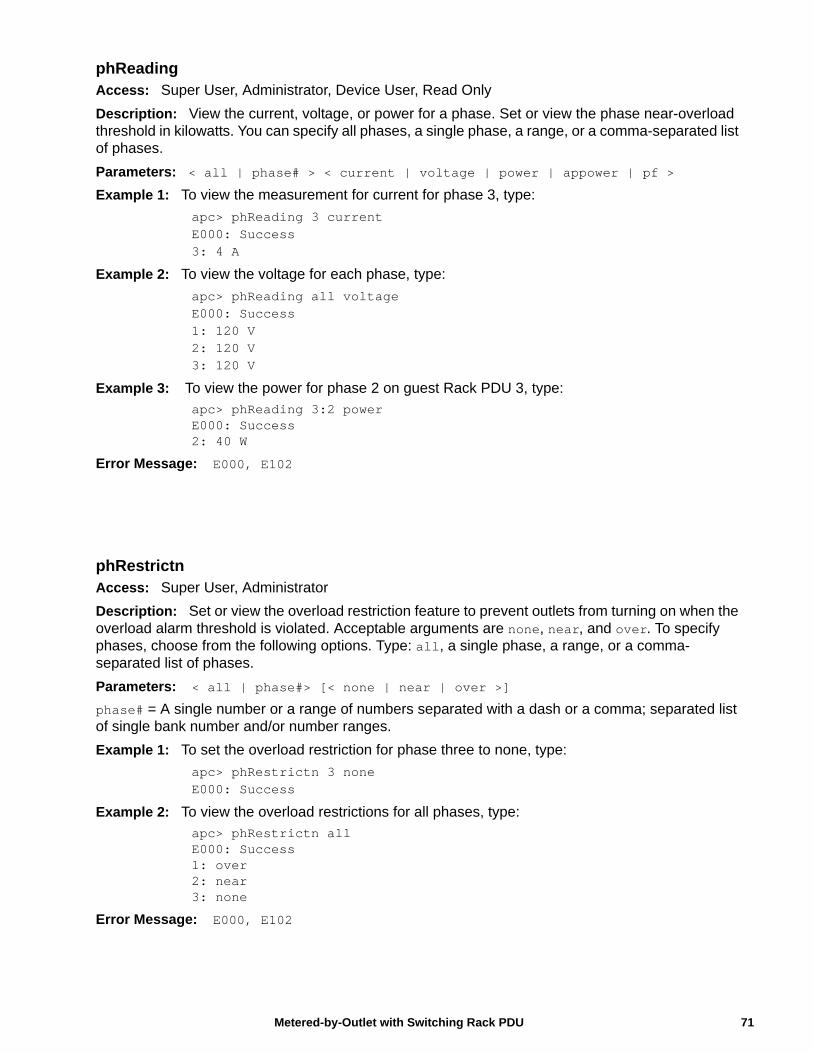
phReadingAccess: Super User, Administrator, Device User, Read Only
Description: View the current, voltage, or power for a phase. Set or view the phase near-overload threshold in kilowatts. You can specify all phases, a single phase, a range, or a comma-separated list of phases.
Parameters: < all | phase# > < current | voltage | power | appower | pf >
Example 1: To view the measurement for current for phase 3, type:
apc> phReading 3 currentE000: Success3: 4 A
Example 2: To view the voltage for each phase, type:
apc> phReading all voltageE000: Success1: 120 V2: 120 V3: 120 V
Example 3: To view the power for phase 2 on guest Rack PDU 3, type:apc> phReading 3:2 powerE000: Success2: 40 W
Error Message: E000, E102
phRestrictnAccess: Super User, Administrator
Description: Set or view the overload restriction feature to prevent outlets from turning on when the overload alarm threshold is violated. Acceptable arguments are none, near, and over. To specify phases, choose from the following options. Type: all, a single phase, a range, or a comma-separated list of phases.
Parameters: < all | phase#> [< none | near | over >]
phase# = A single number or a range of numbers separated with a dash or a comma; separated list of single bank number and/or number ranges.
Example 1: To set the overload restriction for phase three to none, type:
apc> phRestrictn 3 noneE000: Success
Example 2: To view the overload restrictions for all phases, type:
apc> phRestrictn allE000: Success1: over2: near3: none
Error Message: E000, E102
71Metered-by-Outlet with Switching Rack PDU
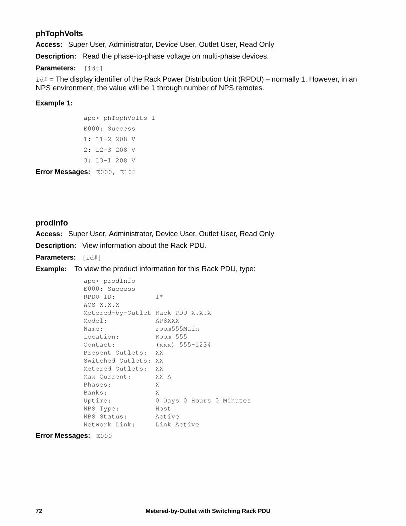
phTophVoltsAccess: Super User, Administrator, Device User, Outlet User, Read Only
Description: Read the phase-to-phase voltage on multi-phase devices.
Parameters: [id#]
id# = The display identifier of the Rack Power Distribution Unit (RPDU) – normally 1. However, in an NPS environment, the value will be 1 through number of NPS remotes.
Example 1:
apc> phTophVolts 1
E000: Success
1: L1-2 208 V
2: L2-3 208 V
3: L3-1 208 V
Error Messages: E000, E102
prodInfoAccess: Super User, Administrator, Device User, Outlet User, Read Only
Description: View information about the Rack PDU.
Parameters: [id#]
Example: To view the product information for this Rack PDU, type:
apc> prodInfoE000: SuccessRPDU ID: 1*AOS X.X.XMetered-by-Outlet Rack PDU X.X.XModel: AP8XXXName: room555MainLocation: Room 555Contact: (xxx) 555-1234Present Outlets: XXSwitched Outlets: XXMetered Outlets: XXMax Current: XX APhases: XBanks: XUptime: 0 Days 0 Hours 0 MinutesNPS Type: HostNPS Status: ActiveNetwork Link: Link Active
Error Messages: E000
Metered-by-Outlet with Switching Rack PDU72
sensorNameAccess: Super User, Administrator, Device User
Description: Set or view the name assigned to the Rack PDU Temp/Humidity port.
Parameters: [id#:][newname]
Example 1: To set the name for the port to “Sensor1,” type:
apc> sensorName Sensor1E000: Success
Example 2: To then view the name for the sensor port, type:
apc> sensorNameE000: SuccessSensor1
Example 3: To set the name for the sensor port on guest Rack PDU 2 to “Sensor1,” type:
apc> sensorName 2:Sensor1E000: Success
Error Messages: E000, E102
73Metered-by-Outlet with Switching Rack PDU
Temperature Sensor Note: You must have installed an optional Schneider Electric Temperature Sensor (AP9335T) to your Rack PDU in order to use the Temperature related commands.
tempHighAccess: Super User, Administrator, Device User
Description: Set or view the high-temperature threshold in either Fahrenheit or Celsius.
Parameters: [id#:] < F | C > [<temperature>] = New high temperature threshold
Example 1: To set the high-temperature threshold to 70º Fahrenheit, type:
apc> tempHigh F 70E000: Success
Example 2: To view the high-temperature threshold in Celsius, type:
apc> tempHigh CE000: Success21 C
Example 3: To view the high-temperature threshold of guest Rack PDU 2 in Fahrenheit, type:
apc> tempHigh 2:FE000: Success70 F
Error Messages: E000, E102
tempHystAccess: Super User, Administrator, Device User
Description: Set and displays the temperature threshold hysteresis
Parameters: [id#:] < F | C > [<temperature>]= new temperature hysteresis value.
Example:
apc> tempHyst F 6
E000: Success
apc> tempHyst C
E000: Success
3 C
Error Message: E000, E102
Metered-by-Outlet with Switching Rack PDU74
tempMaxAccess: Super User, Administrator, Device User
Description: Set or view the max-temperature threshold in either Fahrenheit or Celsius.
Parameters: [id#:] < F | C > [<temperature>]= new max temperature threshold.
Example 1: To set the max-temperature threshold to 80º Fahrenheit, type:
apc> tempMax F 80E000: Success
Example 2: To view the max-temperature threshold in Celsius, type:
apc> tempMax CE000: Success27 C
Example 3: To view the max-temperature threshold of guest Rack PDU 3 in Fahrenheit, type:
apc> tempMax 3:FE000: Success95 F
Error Message: E000, E102
tempReadingAccess: Super User, Administrator, Device User, Outlet User, Read Only
Description: View the temperature value in either Fahrenheit or Celsius from the sensor.
Parameters: [id#:] < F | C > = temperature
Example 1: To view the temperature value in Fahrenheit, type:
apc> tempReading FE000: Success51.1 F
Example 2: To view the temperature value of guest Rack PDU 3 in Celsius, type:
apc> tempReading 2:CE000: Success23.5 C
Error Message: E000, E102, E201
75Metered-by-Outlet with Switching Rack PDU
Metered-by-Outlet with Switching Rack PDU76
userAddAccess: Super User, Administrator
Description: Add an outlet user to the local user database.
The password for the new user will be the same as the user name. To change the password of the user, use the ‘userPasswd’ command.
Parameters:
<user>
user = A user that does NOT exists in the local database
Example: To add a user named Bobby, type:
apc> userAdd BobbyE000: Success
Error Message: E000, E102, E202
userDeleteAccess: Super User, Administrator
Description: Remove an outlet user from the local user database.
Parameters:
<user>
user = A user that exists in the local database
Example: To remove a user named Bobby, type:
apc> userDelete BobbyE000: Success
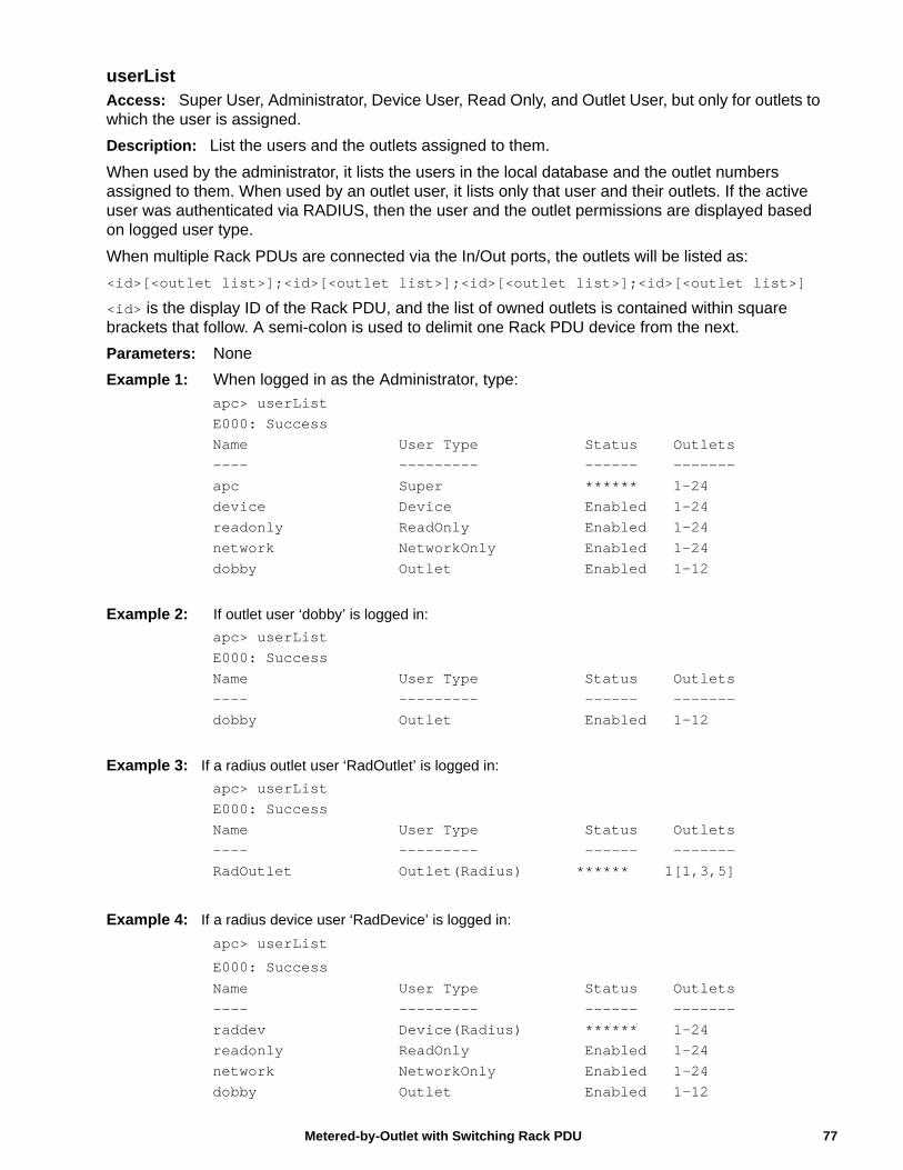
userListAccess: Super User, Administrator, Device User, Read Only, and Outlet User, but only for outlets to which the user is assigned.
Description: List the users and the outlets assigned to them.
When used by the administrator, it lists the users in the local database and the outlet numbers assigned to them. When used by an outlet user, it lists only that user and their outlets. If the active user was authenticated via RADIUS, then the user and the outlet permissions are displayed based on logged user type.
When multiple Rack PDUs are connected via the In/Out ports, the outlets will be listed as:
<id>[<outlet list>];<id>[<outlet list>];<id>[<outlet list>];<id>[<outlet list>]
<id> is the display ID of the Rack PDU, and the list of owned outlets is contained within square brackets that follow. A semi-colon is used to delimit one Rack PDU device from the next.
Parameters: None
Example 1: When logged in as the Administrator, type:apc> userListE000: SuccessName User Type Status Outlets---- --------- ------ -------apc Super ****** 1-24device Device Enabled 1-24readonly ReadOnly Enabled 1-24network NetworkOnly Enabled 1-24dobby Outlet Enabled 1-12
Example 2: If outlet user ‘dobby’ is logged in:
apc> userListE000: SuccessName User Type Status Outlets---- --------- ------ -------dobby Outlet Enabled 1-12
Example 3: If a radius outlet user ‘RadOutlet’ is logged in:
apc> userListE000: SuccessName User Type Status Outlets---- --------- ------ -------RadOutlet Outlet(Radius) ****** 1[1,3,5]
Example 4: If a radius device user ‘RadDevice’ is logged in:
apc> userList
E000: Success
Name User Type Status Outlets---- --------- ------ -------raddev Device(Radius) ****** 1-24readonly ReadOnly Enabled 1-24network NetworkOnly Enabled 1-24dobby Outlet Enabled 1-12
77Metered-by-Outlet with Switching Rack PDU
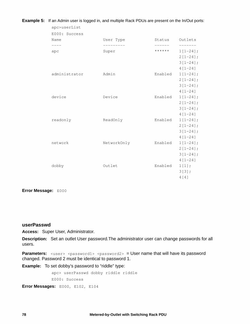
Example 5: If an Admin user is logged in, and multiple Rack PDUs are present on the In/Out ports:
apc>userList
E000: Success
Name User Type Status Outlets---- --------- ------ -------apc Super ****** 1[1-24]; 2[1-24]; 3[1-24]; 4[1-24]administrator Admin Enabled 1[1-24]; 2[1-24]; 3[1-24]; 4[1-24]device Device Enabled 1[1-24]; 2[1-24]; 3[1-24]; 4[1-24]readonly ReadOnly Enabled 1[1-24]; 2[1-24]; 3[1-24]; 4[1-24]network NetworkOnly Enabled 1[1-24]; 2[1-24]; 3[1-24]; 4[1-24]dobby Outlet Enabled 1[1]; 3[3]; 4[4]
Error Message: E000
userPasswdAccess: Super User, Administrator.
Description: Set an outlet User password.The administrator user can change passwords for all users.
Parameters: <user> <password1> <password2> = User name that will have its password changed. Password 2 must be identical to password 1.
Example: To set dobby’s password to “riddle” type:
apc> userPasswd dobby riddle riddle
E000: Success
Error Messages: E000, E102, E104
Metered-by-Outlet with Switching Rack PDU78
Web Interface
Supported Web BrowsersYou can use Microsoft® Internet Explorer® (IE) 7.x and higher (on Windows® operating systems only) or Mozilla® Firefox® 3.0.6 or higher (on all operating systems) to access the Rack PDU through its Web interface. Other commonly available browsers may work but have not been fully tested by APC.
The Rack PDU cannot work with a proxy server. Before you can use a Web browser to access the Web interface of the Rack PDU, you must do one of the following:
• Configure the Web browser to disable the use of a proxy server for the Rack PDU.
• Configure the proxy server so that it does not proxy the specific IP address of the Rack PDU.
Log On to the Web Interface
Overview
You can use the DNS name or System IP address of the Rack PDU for the URL address of the Web interface. Use your case-sensitive user name and password to log on.
The default user name and password for the Super User are both apc. For all other user types, there is no default user name or password. The Super User or an Administrator created by the Super User, must define the user name and password and other account characteristics for these users.
Note: If you are using HTTPS (SSL/TLS) as your access protocol, your login credentials are compared with information in a server certificate. If the certificate was created with the Security Wizard, and an IP address was specified as the common name in the certificate, you must use an IP address to log on to the Rack PDU. If a DNS name was specified as the common name on the certificate, you must use a DNS name to log on.
URL address formats
Type the DNS name or IP address of the Rack PDU in the Web browser’s URL address field and press ENTER. When you specify a non-default Web server port in Internet Explorer, you must include http:// or https:// in the URL.
Common browser error messages at log-on
Error Message Browser Cause of the Error
“This page cannot be displayed.” Internet Explorer Web access is disabled, or the URL was not correct.
“Unable to connect.” Firefox
79Metered-by-Outlet with Switching Rack PDU
URL format examples
• For a DNS name of Web1:
– http://Web1 if HTTP is your access mode
– https://Web1 if HTTPS (HTTP with SSL) is your access mode
• For a System IP address of 139.225.6.133 and the default Web server port (80):
– http://139.225.6.133 if HTTP is your access mode
– https//139.225.6.133 if HTTPS (HTTP with SSL) is your access mode
• For a System IP address of 139.225.6.133 and a non-default Web server port (5000):
– http://139.225.6.133:5000 if HTTP is your access mode
– https://139.225.6.133:5000 if HTTPS (HTTP with SSL) is your access mode
• For a System IPv6 address of 2001:db8:1::2c0:b7ff:fe00:1100 and a non-default Web server port (5000):http://[2001:db8:1::2c0:b7ff:fe00:1100]:5000 if HTTP is your access mode
Web Interface FeaturesRead the following to familiarize yourself with basic Web interface features for your Rack PDU.
Tabs
The following tabs are available:
• Home: Appears when you log on (This is the default tab when you log on. To change the login page to a different page, click on the green pushpin at the top right side of the browser window while on the desired page). View active alarms, the load status of the Rack PDU, and the most recent Rack PDU events. For more information, see “About Home” on page 83.
• Status: Gives the user the status of the Rack PDU and Network. The RPDU tab covers the status of alarms, groups, device, phase, bank, and environment. Network tab covers just the network. See “Status Tab” on page 84.
• Control: The Control tab covers three topics: RPDU, Security and Network. Much more information is covered under each of these tabs and will be described in the Control tab section.
• Configuration: The Configuration tab covers RPDU, Security, Network, Notification, General and Logs. Much more information is covered under each of these tabs and will be described in the Configuration tab section.
• Tests: The Tests tab covers Rack PDU and Network. The RPDU tab covers LCD Blink and the Network tab covers LED Blink. Both will be further described later in the Tests section of the document.
• Logs: The Logs section covers: Event, Data and Firewall. The Event and Data tabs cover more information which will be further discussed later in the Logs section of the document.
• About: The About section covers RPDU and Network, which will be further discussed later in the About section of the document.
Metered-by-Outlet with Switching Rack PDU80
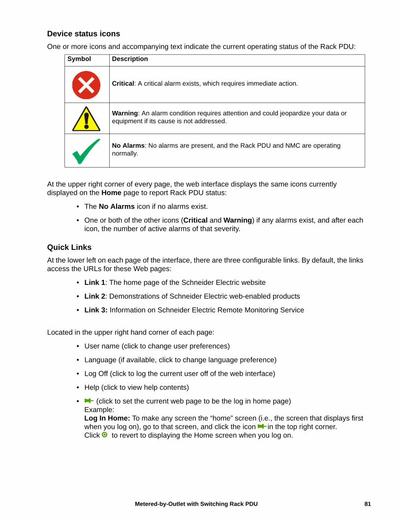
Device status icons
One or more icons and accompanying text indicate the current operating status of the Rack PDU:
At the upper right corner of every page, the web interface displays the same icons currently displayed on the Home page to report Rack PDU status:
• The No Alarms icon if no alarms exist.
• One or both of the other icons (Critical and Warning) if any alarms exist, and after each icon, the number of active alarms of that severity.
Quick Links
At the lower left on each page of the interface, there are three configurable links. By default, the links access the URLs for these Web pages:
• Link 1: The home page of the Schneider Electric website
• Link 2: Demonstrations of Schneider Electric web-enabled products
• Link 3: Information on Schneider Electric Remote Monitoring Service
Located in the upper right hand corner of each page:
• User name (click to change user preferences)
• Language (if available, click to change language preference)
• Log Off (click to log the current user off of the web interface)
• Help (click to view help contents)
• (click to set the current web page to be the log in home page)Example:Log In Home: To make any screen the “home” screen (i.e., the screen that displays first when you log on), go to that screen, and click the icon in the top right corner. Click to revert to displaying the Home screen when you log on.
Symbol Description
Critical: A critical alarm exists, which requires immediate action.
Warning: An alarm condition requires attention and could jeopardize your data or equipment if its cause is not addressed.
No Alarms: No alarms are present, and the Rack PDU and NMC are operating normally.
81Metered-by-Outlet with Switching Rack PDU
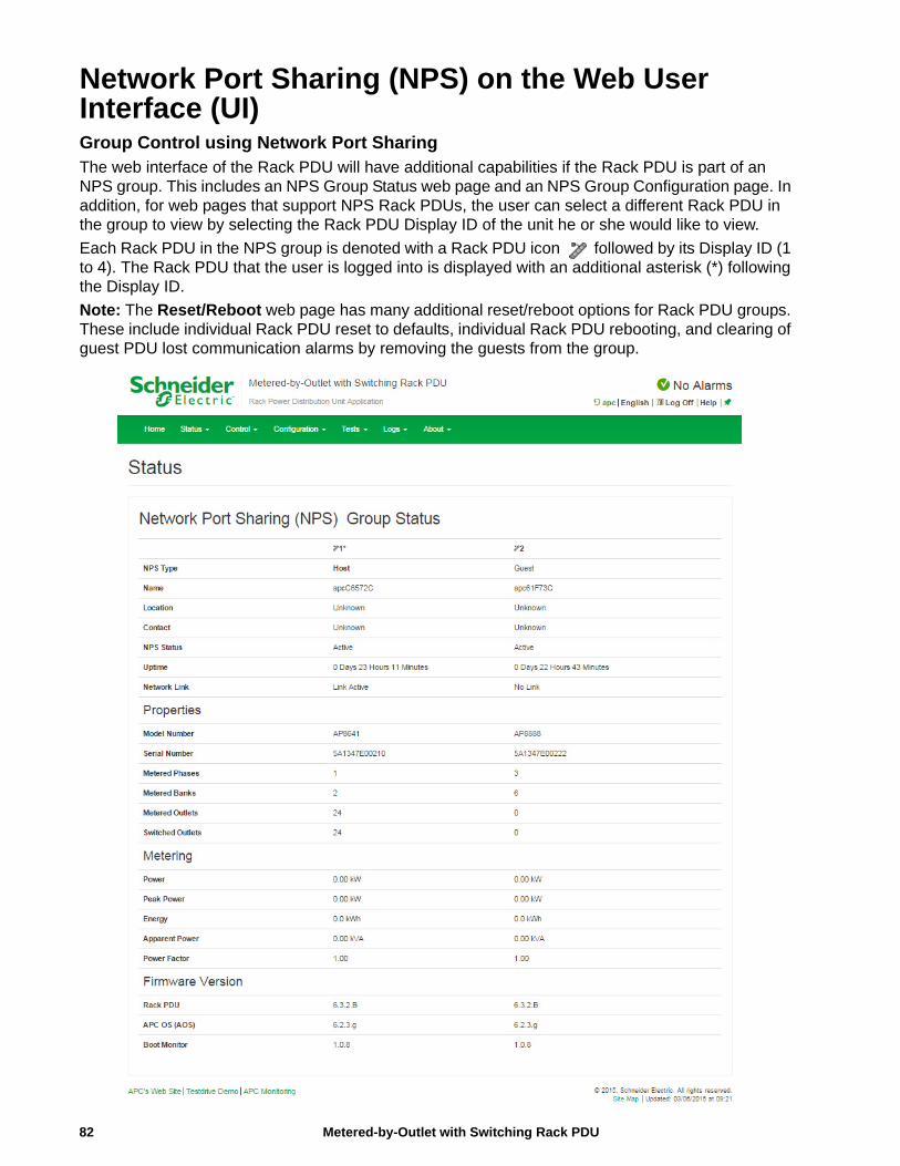
Network Port Sharing (NPS) on the Web User Interface (UI)Group Control using Network Port SharingThe web interface of the Rack PDU will have additional capabilities if the Rack PDU is part of an NPS group. This includes an NPS Group Status web page and an NPS Group Configuration page. In addition, for web pages that support NPS Rack PDUs, the user can select a different Rack PDU in the group to view by selecting the Rack PDU Display ID of the unit he or she would like to view.
Each Rack PDU in the NPS group is denoted with a Rack PDU icon followed by its Display ID (1 to 4). The Rack PDU that the user is logged into is displayed with an additional asterisk (*) following the Display ID.
Note: The Reset/Reboot web page has many additional reset/reboot options for Rack PDU groups. These include individual Rack PDU reset to defaults, individual Rack PDU rebooting, and clearing of guest PDU lost communication alarms by removing the guests from the group.
Metered-by-Outlet with Switching Rack PDU82
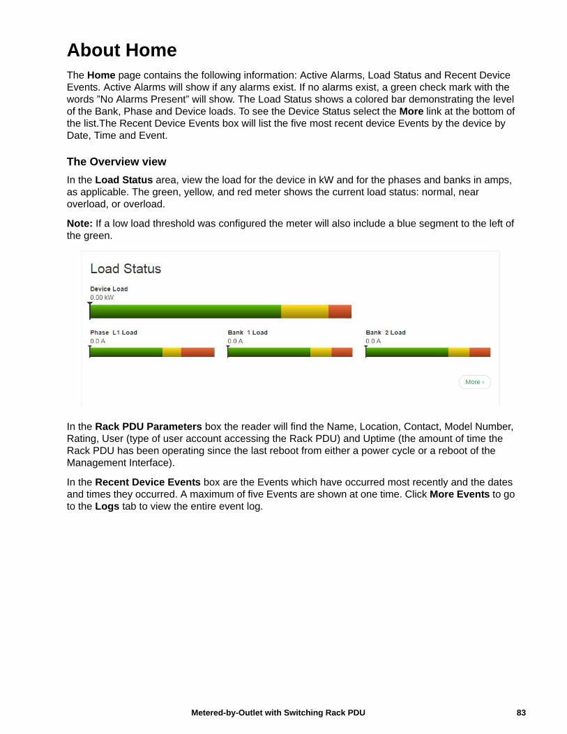
83Metered-by-Outlet with Switching Rack PDU
About HomeThe Home page contains the following information: Active Alarms, Load Status and Recent Device Events. Active Alarms will show if any alarms exist. If no alarms exist, a green check mark with the words ”No Alarms Present” will show. The Load Status shows a colored bar demonstrating the level of the Bank, Phase and Device loads. To see the Device Status select the More link at the bottom of the list.The Recent Device Events box will list the five most recent device Events by the device by Date, Time and Event.
The Overview view
In the Load Status area, view the load for the device in kW and for the phases and banks in amps, as applicable. The green, yellow, and red meter shows the current load status: normal, near overload, or overload.
Note: If a low load threshold was configured the meter will also include a blue segment to the left of the green.
In the Rack PDU Parameters box the reader will find the Name, Location, Contact, Model Number, Rating, User (type of user account accessing the Rack PDU) and Uptime (the amount of time the Rack PDU has been operating since the last reboot from either a power cycle or a reboot of the Management Interface).
In the Recent Device Events box are the Events which have occurred most recently and the dates and times they occurred. A maximum of five Events are shown at one time. Click More Events to go to the Logs tab to view the entire event log.
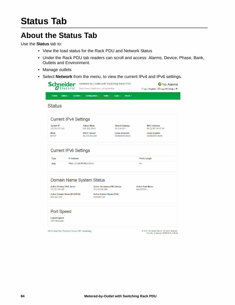
Status Tab
About the Status TabUse the Status tab to:
• View the load status for the Rack PDU and Network Status
• Under the Rack PDU tab readers can scroll and access: Alarms, Device, Phase, Bank, Outlets and Environment.
• Manage outlets
• Select Network from the menu, to view the current IPv4 and IPv6 settings.
Metered-by-Outlet with Switching Rack PDU84
View the Load Status and Peak Load
Path: Status > RPDU
Alarms: Lists Device Alarm Status.
Group: Network Port sharing Group Status. List the Properties, Metering and firmware version information. Change Host RPDU can be accessed from its link at the bottom of the page.
Device: Shows status of device. Lists Status, Properties and Configuration information.
Phase: Shows Phase Status. The phase settings can also be configured via a Configure Phase Settings link at the bottom of the page. Configuration can be changed as well.
Bank:Shows bank status (only on units with this feature). List current size and demonstrates range on a colored red, green and yellow sliding bar. The bank settings can be changed via a Configure Bank status link at the bottom of the page.
Outlet:Shows: Outlet Name, Phase, State and Outlet Load
Switched Outlet:Choose from the following options:
• Scheduling: Shows Scheduled outlet actions.
• Outlet Groups: Shows outlet groups as either enabled or disabled and can also configure.
Environment:Shows Alarm Status, Temperature, Humidity and can configure Temperature and Humidity Configuration after pressing the Configure link.
View the Network Status
Path: Status > Network
The Network screen displays information about your network.
Current IPv4 Settings
System IP. The IP address of the unit.
Subnet Mask. The IP address of the sub-network.
Default Gateway. The IP address of the router used to connect to the network.
MAC Address. The MAC address of the unit.
Mode. How the IPv4 settings are assigned: Manual, DHCP, or BOOTP.
DHCP Server. The IP address of the DHCP server. This is only displayed if Mode is DHCP.
Lease Acquired. The date/time that the IP address was accepted from the DHCP server.
Lease Expires. The date/time that the IP address accepted from the DHCP server expires and will need to be renewed.
Current IPv6 Settings
Type. How the IPv6 settings are assigned.
IP Address. The IP address of the unit.
Prefix Length. The range of addresses for the sub-network.
85Metered-by-Outlet with Switching Rack PDU
Domain Name System Status
Active Primary DNS Server. The IP address of the primary DNS server.
Active Secondary DNS Server. The IP address of the secondary DNS server.
Active Host Name. The host name of the active DNS server.
Active Domain Name (IPv4/IPv6). The IPv4/IPv6 domain name that is currently in use.
Active Domain Name (IPv6). The IPv6 domain name that is currently in use.
Ethernet Port Speed
Current Speed. The current speed assigned to the Ethernet port.
Metered-by-Outlet with Switching Rack PDU86
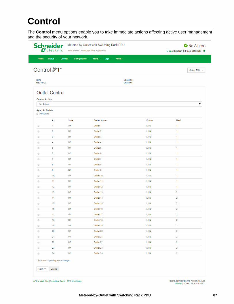
87Metered-by-Outlet with Switching Rack PDU
ControlThe Control menu options enable you to take immediate actions affecting active user management and the security of your network.
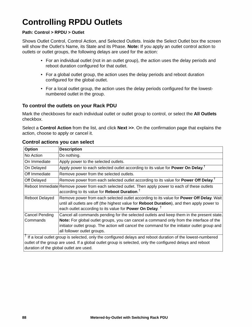
Controlling RPDU OutletsPath: Control > RPDU > Outlet
Shows Outlet Control, Control Action, and Selected Outlets. Inside the Select Outlet box the screen will show the Outlet’s Name, its State and its Phase. Note: If you apply an outlet control action to outlets or outlet groups, the following delays are used for the action:
• For an individual outlet (not in an outlet group), the action uses the delay periods and reboot duration configured for that outlet.
• For a global outlet group, the action uses the delay periods and reboot duration configured for the global outlet.
• For a local outlet group, the action uses the delay periods configured for the lowest-numbered outlet in the group.
To control the outlets on your Rack PDU
Mark the checkboxes for each individual outlet or outlet group to control, or select the All Outlets checkbox.
Select a Control Action from the list, and click Next >>. On the confirmation page that explains the action, choose to apply or cancel it.
Control actions you can selectOption Description
No Action Do nothing.
On Immediate Apply power to the selected outlets.
On Delayed Apply power to each selected outlet according to its value for Power On Delay.†
Off Immediate Remove power from the selected outlets.
Off Delayed Remove power from each selected outlet according to its value for Power Off Delay.†
Reboot Immediate Remove power from each selected outlet. Then apply power to each of these outlets according to its value for Reboot Duration.†
Reboot Delayed Remove power from each selected outlet according to its value for Power Off Delay. Wait until all outlets are off (the highest value for Reboot Duration), and then apply power to each outlet according to its value for Power On Delay. †
Cancel Pending Commands
Cancel all commands pending for the selected outlets and keep them in the present state.Note: For global outlet groups, you can cancel a command only from the interface of the initiator outlet group. The action will cancel the command for the initiator outlet group and all follower outlet groups.
† If a local outlet group is selected, only the configured delays and reboot duration of the lowest-numbered outlet of the group are used. If a global outlet group is selected, only the configured delays and reboot duration of the global outlet are used.
Metered-by-Outlet with Switching Rack PDU88
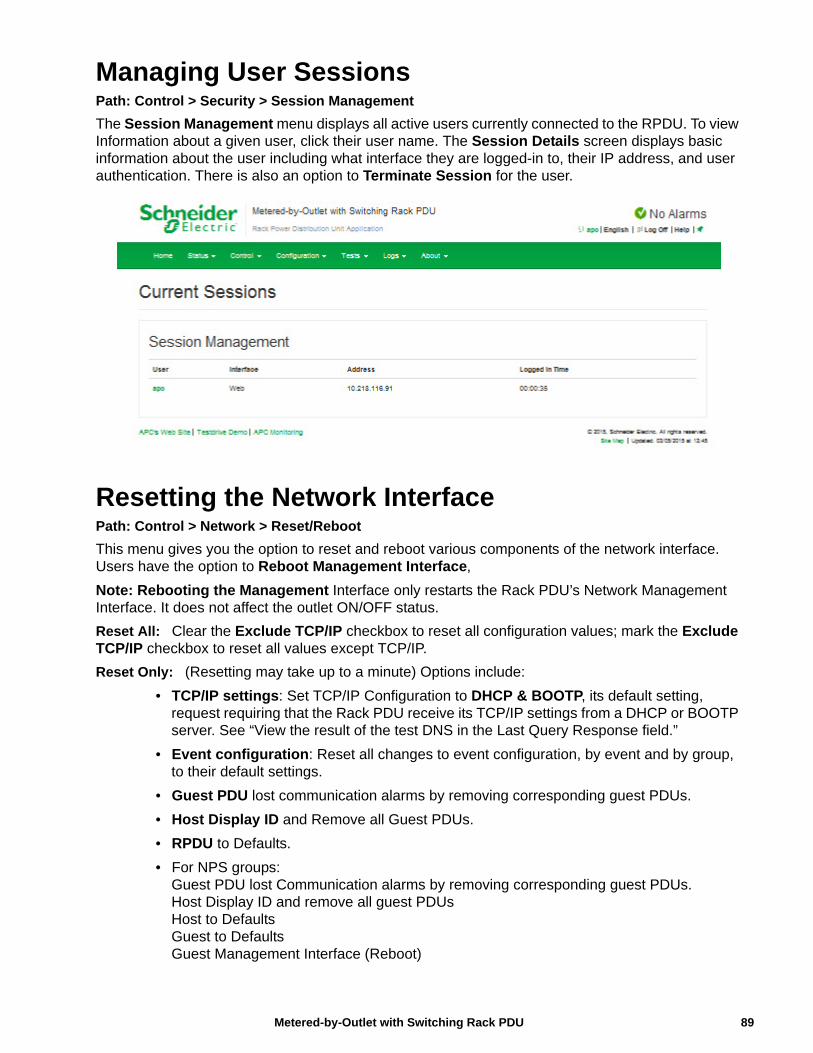
Managing User SessionsPath: Control > Security > Session Management
The Session Management menu displays all active users currently connected to the RPDU. To view Information about a given user, click their user name. The Session Details screen displays basic information about the user including what interface they are logged-in to, their IP address, and user authentication. There is also an option to Terminate Session for the user.
Resetting the Network InterfacePath: Control > Network > Reset/Reboot
This menu gives you the option to reset and reboot various components of the network interface. Users have the option to Reboot Management Interface,
Note: Rebooting the Management Interface only restarts the Rack PDU’s Network Management Interface. It does not affect the outlet ON/OFF status.
Reset All: Clear the Exclude TCP/IP checkbox to reset all configuration values; mark the Exclude TCP/IP checkbox to reset all values except TCP/IP.
Reset Only: (Resetting may take up to a minute) Options include:
• TCP/IP settings: Set TCP/IP Configuration to DHCP & BOOTP, its default setting, request requiring that the Rack PDU receive its TCP/IP settings from a DHCP or BOOTP server. See “View the result of the test DNS in the Last Query Response field.”
• Event configuration: Reset all changes to event configuration, by event and by group, to their default settings.
• Guest PDU lost communication alarms by removing corresponding guest PDUs.
• Host Display ID and Remove all Guest PDUs.
• RPDU to Defaults.
• For NPS groups:Guest PDU lost Communication alarms by removing corresponding guest PDUs.Host Display ID and remove all guest PDUsHost to DefaultsGuest to DefaultsGuest Management Interface (Reboot)
89Metered-by-Outlet with Switching Rack PDU
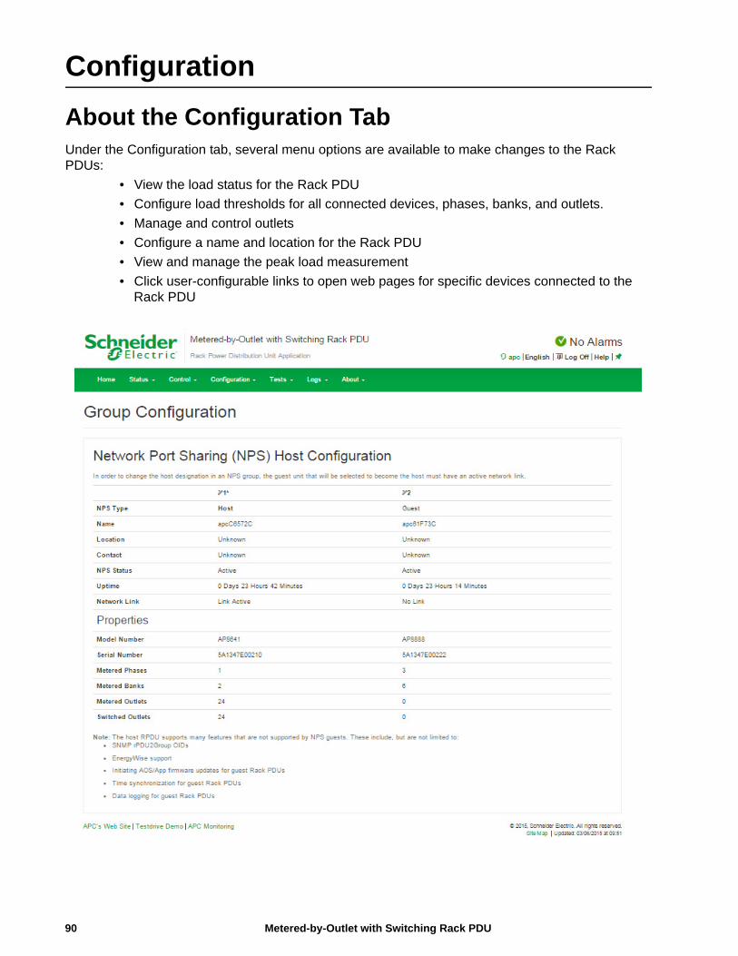
Configuration
About the Configuration TabUnder the Configuration tab, several menu options are available to make changes to the Rack PDUs:
• View the load status for the Rack PDU
• Configure load thresholds for all connected devices, phases, banks, and outlets.
• Manage and control outlets
• Configure a name and location for the Rack PDU
• View and manage the peak load measurement
• Click user-configurable links to open web pages for specific devices connected to the Rack PDU
Metered-by-Outlet with Switching Rack PDU90
Configure Load ThresholdsPath: Configuration > RPDU
View the load for the device, phases, banks, and outlets. The indicator in the green, yellow, and red meter shows the current load status: normal, near overload, or overload. If a low load threshold was configured, the meter will include a blue segment to the left of the green. When viewing the Device Load, the triangle above the meter indicates peak load.
Note: The Rack PDU generates an alarm when any bank exceeds its rated value. However, if a circuit breaker trips, there is no definitive indication that the circuit breaker is open, other than that the current for that bank will drop. Set the Low Load Warning to 1 amp for these reasons:
• The default setting for the Low Load Warning is 0 amps. This effectively disables the warning. With a setting of 0 amps for the Low Load Warning, the web interface will not indicate that a circuit breaker may have tripped.
• A 1 amp detection threshold for the Low Load Warning for Bank Load Management will help to indicate that a circuit breaker may have tripped.
To configure load thresholds1. To configure load thresholds for the device, phases, or banks, make a selection from the
Configuration > RPDU > Device and Phase and Bank drop-down menu. To configure load thresholds for outlets, click Configuration and then click an outlet.
2. Set Overload Alarm, Near Overload Warning, and Low Load Warning thresholds.
3. Click Apply to save your settings.
Configure RPDU Name and LocationPath: Configuration > RPDU > Device
The name and location you enter will appear on the Home tab.
1. Enter a name and location and contact.
2. Click Apply to save.
Set the Coldstart Delay for the Rack PDUPath: Configuration > RPDU > Device
The Coldstart Delay is the number of seconds added to each outlet’s Power On Delay before an outlet will turn on after power is applied to the Rack PDU. Allowed values are from 1 to 300 seconds, Immediate, or Never (never turn on).
1. Make a selection for Coldstart Delay.
2. Click Apply.
Reset Peak Load and kWhPath: Configuration > RPDU > Device
1. Click the Configuration tab, then RPDU, then Device.
2. Click the Peak Load and Kilowatt-Hours check boxes as desired.
3. Click Apply.
91Metered-by-Outlet with Switching Rack PDU
Set the Overload Outlet RestrictionsPath: Configuration > RPDU > Phase and Bank
Prevent users from applying power to outlets during an overload condition. You can set the following restrictions for each phase and bank:
• None: Users can apply power to outlets regardless of an Overload Alarm or Near Overload Warning.
• On Warning: Users cannot apply power to an outlet on the selected phase or bank if the current for that phase or bank has exceeded the Near Overload Warning threshold.
• On Overload: Users cannot apply power to an outlet on the selected phase or bank if the current for that phase or bank has exceeded the Overload Alarm threshold.
To set Overload Outlet Restrictions:1. Click the Configuration tab, then RPDU, then phase or bank from the menu.
2. Make selections for Overload Outlet Restriction.
3. Click Apply.
Configure and Control Outlet GroupsOutlet group terminologyAn outlet group consists of outlets that are logically linked together on the same Rack PDU. Outlets that are in an outlet group turn on, turn off, and reboot in a synchronized manner:
• A local outlet group consists of two or more outlets on a Rack PDU. Only the outlets in that group are synchronized.
• A global outlet group consists of one or more outlets on a Rack PDU. One outlet is configured as a global outlet, which logically links the outlet group to outlet groups on up to three other Rack PDUs. All outlets in the linked global outlet groups are synchronized.
– For global outlet groups, the initiator outlet group is the group that issued the action.
– For global outlet groups, a follower outlet group is any other outlet group that is synchronized with the initiator outlet group.
When you apply an outlet control action to outlets that are members of an outlet group, the outlets are synchronized as follows:
• For a global outlet group, use the delay periods and reboot duration configured for the global outlet of the initiator outlet group.
• For a local outlet group, the outlets use the delay periods and reboot duration of the lowest-numbered outlet in the group.
Purpose and benefits of outlet groupsBy using groups of synchronized outlets on Rack PDUs, you can ensure that outlets turn on, turn off, and reboot in a synchronized manner. Synchronizing control group actions through outlet groups provides the following benefits.
• Synchronized shutdown and startup of the power supplies of dual-corded servers prevents erroneous reporting of power supply failures during a planned system shutdown or reboot.
• Synchronizing outlets by using outlet groups provides more precise shutdown and restart timing than relying on the delay periods of individual outlets.
• A global outlet is visible to the user interface of any Rack PDU to which it is linked.
Metered-by-Outlet with Switching Rack PDU92
System requirements for outlet groups
To set up and use synchronized outlet control groups:
• You need a computer that can initiate synchronized control operations through the Web interface or command line interface of the Rack PDUs or through SNMP.
• All of the Rack PDUs must use firmware that has the same version number for both Schneider Electric’s APC Operating System (AOS) module and the application module.
• All of the Rack PDUs must be configured with the same “Member Name”.
• If you are using Network mode, you will also need the following items. These are not necessary if you are using Network Port Sharing mode over the In/Out ports.
– You need a 10/100Base-T TCP/IP network, with an Ethernet hub or switch that has a power source not shared by the computers or other devices being synchronized.
– All of the Rack PDUs must be on the same subnet.
– Outlet groups you synchronize must have the same Multicast IP address, outlet group port, authentication phrase, and encryption phrase. Make sure each Ethernet switch that connects Rack PDUs allows Multicast network traffic for that Multicast IP address.
Rules for configuring outlet groups
For a system that uses outlet groups, the following rules apply:
• A Rack PDU can have more than one outlet group, but an outlet can belong to only one outlet group.
• A local outlet group, which has no global outlet, must consist of two or more outlets.
• You can synchronize a global outlet group on one Rack PDU with a global outlet group on each of three other Rack PDUs.
– In a global outlet group, you can designate only one outlet to be a global outlet, linking to outlet groups on other Rack PDUs for the purpose of synchronization. That global outlet can be the only outlet in its group, or the group can consist of multiple outlets.
– A global outlet of one outlet group must have the same physical outlet number as the global outlet of any other outlet group to which it links.
• To create and configure outlet groups, you must use the Web interface or export configuration file (.ini file) settings from a configured Rack PDU. The command line interface lets you display whether an outlet is a member of an outlet group and lets you apply control actions to an outlet group, but the command line interface does not let you set up or configure an outlet group.
93Metered-by-Outlet with Switching Rack PDU
Enable outlet groups
Path: Configuration > RPDU > Switched Outlet > Outlet Groups
Configure the following parameters, and click Apply.
Enable creation of outlet groups
Enable support for global outlet groups (linked groups)
Setting parameters for outlet groups using Network mode
Note: Devices attempting to synchronize with Outlet Groups on other devices using network mode must all have the same Authentication Phrase and Encryption Phrase. The values are hidden to the user.
Create a local outlet group
Path: Configuration > RPDU > Switched Outlet > Outlet Groups
1. Make sure outlet groups are enabled. (See “Typical outlet group configurations” on page 96.)
2. Click Create Local Outlet Group.
3. Select the checkboxes of the outlets that will be in the group and assign the group a name in the Outlet Group Name field. You must select at least two outlets.
Parameters Description
Device Level Outlet Group
To create an outlet group, you must enable the desired group method. Choices are Disabled, Local Only, Enabled via Network, and Enabled via In/Out Ports (Network Port Sharing).
Parameters Description
Member Name To link outlet groups on multiple Switched Rack PDUs, you must define the same Member name on each of the Rack PDUs.Note: A maximum of four devices can be configured with the same Member name
Parameters Description
Multicast IP To link outlet groups on multiple Switched Rack PDUs, you must define the same Multicast IP address on each of the Rack PDUs.Note: A maximum of four devices can be configured with the same Member name and Multicast IP address.
Authentication Phrase
A phrase of 15 to 32 ASCII characters that verifies that the device is communicating with other devices, that the message has not been changed during transmission, and that the message was communicated in a timely manner. The authentication phrase indicates that it was not delayed and that it was not copied and sent again later at an inappropriate time.
Encryption Phrase A phrase of 15 to 32 ASCII characters that ensures the privacy of the data (by means of encryption).
Outlet Group Port The port number on which the device will communicate with other devices. This must be the same on all PDUs in a group.
Metered-by-Outlet with Switching Rack PDU94

Create a global outlet group
Path: Configuration > RPDU > Switched Outlet > Outlet Groups
To set up multiple global outlet groups that link to outlet groups on other Rack PDUs:
1. Make sure outlet groups are enabled. (See “Typical outlet group configurations” on page 96.)
2. Click Create Global Outlet Groups.
3. Select the checkboxes of the outlets that will be in the group and then click "Apply and Select Global Outlets" to select the global outlet for the group. If there is only one outlet in the group, it will automatically be assigned as the global outlet.
4. To add outlets to any of the global outlet groups you created, see “Edit or delete an outlet group” .
Edit or delete an outlet group
Path: Configuration > RPDU > Switched Outlet > Outlet Groups
1. In the Configure Group table, click on the number or name of the outlet group to edit or delete.
2. When editing an outlet group you can do any of the following:
– Rename the outlet group.
– Add or remove outlets by clicking the checkboxes to mark or unmark them.
Note: You cannot remove an outlet from an outlet group that contains only two outlets unless the remaining outlet is a global outlet.
3. To delete the outlet group, click Delete Outlet Group.
95Metered-by-Outlet with Switching Rack PDU
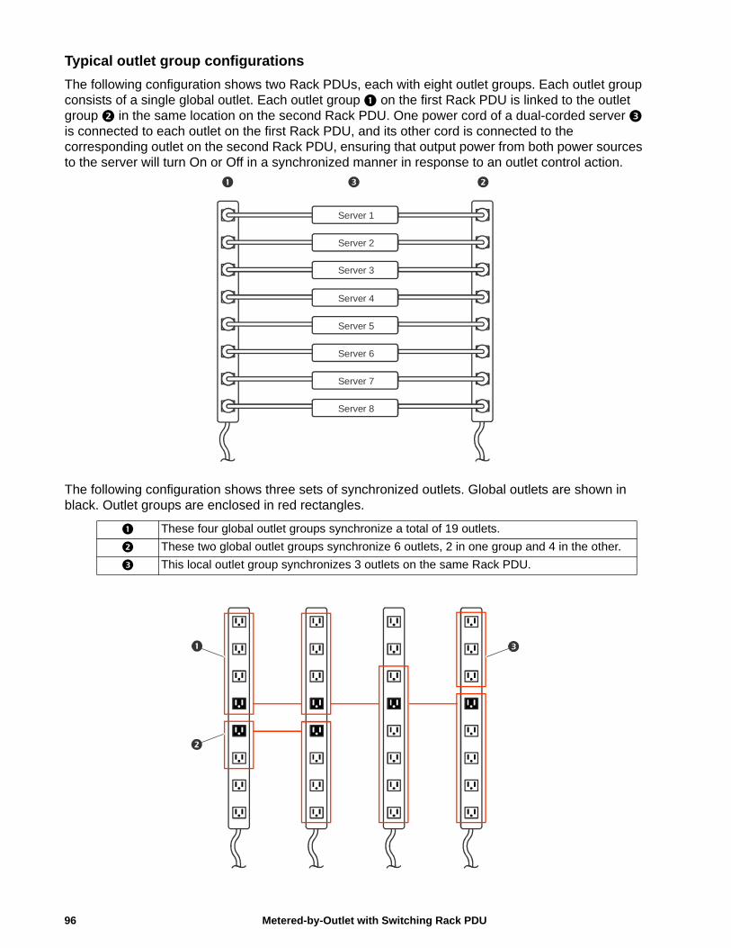
Typical outlet group configurations
The following configuration shows two Rack PDUs, each with eight outlet groups. Each outlet group consists of a single global outlet. Each outlet group on the first Rack PDU is linked to the outlet group in the same location on the second Rack PDU. One power cord of a dual-corded server is connected to each outlet on the first Rack PDU, and its other cord is connected to the corresponding outlet on the second Rack PDU, ensuring that output power from both power sources to the server will turn On or Off in a synchronized manner in response to an outlet control action.
The following configuration shows three sets of synchronized outlets. Global outlets are shown in black. Outlet groups are enclosed in red rectangles.
These four global outlet groups synchronize a total of 19 outlets.
These two global outlet groups synchronize 6 outlets, 2 in one group and 4 in the other.
This local outlet group synchronizes 3 outlets on the same Rack PDU.
Server 1
Server 2
Server 3
Server 4
Server 5
Server 6
Server 7
Server 8
Metered-by-Outlet with Switching Rack PDU96
Verify your setup and configuration for global outlet groups
Path: Configuration > RPDU > Switched Outlet > Outlet Groups
To ensure that your setup meets all system requirements for outlet groups and that you have configured the outlet groups correctly, view the groups and their connections:
• The Configure Group table displays the following:
– All configured outlet groups on the current Rack PDU.
– The outlets in each group by outlet number.
– Any outlet groups on other Rack PDUs with which a global outlet group is synchronized. Each Rack PDU is identified by its IP address if using network mode, or Display ID if using Network Port Sharing over In/Out ports. Each global outlet is displayed in bold text.
• The Global Outlet Overview section displays the following:
– The IP address or Display ID of the current Rack PDU.
– The IP address or Display ID of any Rack PDUs that contain global outlets that are available to be synchronized with outlet groups on other Rack PDUs.
– All global outlets configured on the Rack PDUs, regardless of whether they are synchronized with outlet groups on the current Rack PDU.
Outlet SettingsSelect From the options to control the outlets on your Rack PDU.
Path: Configuration > RPDU > Switched Outlet (or Outlet Groups)
Configure outlet settings and the outlet name
The following settings are available:
Setting Description
Name Set the name for one or more outlets. The name is displayed next to the outlet number on status screens.
External Link Define an HTTP or HTTPS link to a web site or IP address.The external device web link can be set to the IP address of the external device plugged into the outlet (if applicable). Alternatively, it can be set to the device's manufacturer web page in order to more easily view user manuals, etc. Clicking the link on the Outlet Links page will open a new browser window to the link.
Power On Delay Set the number of seconds that the Rack PDU waits after a command is issued before applying power to an outlet.Note:To configure an outlet to remain off at all times, select the Never radio button next to Power On Delay.
Power Off Delay Set the number of seconds that the Rack PDU waits after a command is issued before removing power from an outlet.Note: To configure an outlet to remain on at all times, select the Never radio button next to Power Off Delay.
Reboot Duration Set the number of seconds an outlet remains Off before restarting.
97Metered-by-Outlet with Switching Rack PDU
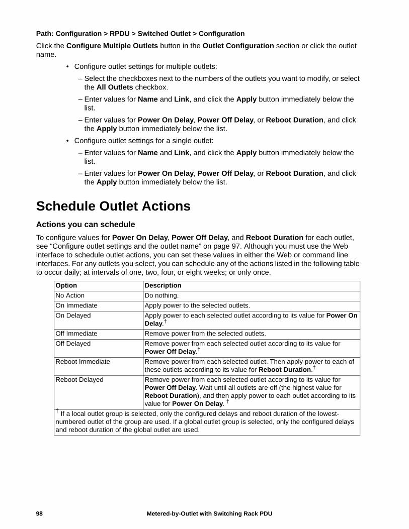
Path: Configuration > RPDU > Switched Outlet > Configuration
Click the Configure Multiple Outlets button in the Outlet Configuration section or click the outlet name.
• Configure outlet settings for multiple outlets:
– Select the checkboxes next to the numbers of the outlets you want to modify, or select the All Outlets checkbox.
– Enter values for Name and Link, and click the Apply button immediately below the list.
– Enter values for Power On Delay, Power Off Delay, or Reboot Duration, and click the Apply button immediately below the list.
• Configure outlet settings for a single outlet:
– Enter values for Name and Link, and click the Apply button immediately below the list.
– Enter values for Power On Delay, Power Off Delay, or Reboot Duration, and click the Apply button immediately below the list.
Schedule Outlet ActionsActions you can schedule
To configure values for Power On Delay, Power Off Delay, and Reboot Duration for each outlet, see “Configure outlet settings and the outlet name” on page 97. Although you must use the Web interface to schedule outlet actions, you can set these values in either the Web or command line interfaces. For any outlets you select, you can schedule any of the actions listed in the following table to occur daily; at intervals of one, two, four, or eight weeks; or only once.
Option Description
No Action Do nothing.
On Immediate Apply power to the selected outlets.
On Delayed Apply power to each selected outlet according to its value for Power On Delay.†
Off Immediate Remove power from the selected outlets.
Off Delayed Remove power from each selected outlet according to its value for Power Off Delay.†
Reboot Immediate Remove power from each selected outlet. Then apply power to each of these outlets according to its value for Reboot Duration.†
Reboot Delayed Remove power from each selected outlet according to its value for Power Off Delay. Wait until all outlets are off (the highest value for Reboot Duration), and then apply power to each outlet according to its value for Power On Delay. †
† If a local outlet group is selected, only the configured delays and reboot duration of the lowest-numbered outlet of the group are used. If a global outlet group is selected, only the configured delays and reboot duration of the global outlet are used.
Metered-by-Outlet with Switching Rack PDU98
Schedule an outlet event
Path: Configuration > RPDU > Switched Outlet > Scheduling
1. On the Outlet Scheduling page, select how often the event will occur (One-Time, Daily, or Weekly), and click the Next button.Note: If you select Weekly, you can choose to have the event occur once every week or once every two, four, or eight weeks.
2. On the Schedule a Daily Action page, in the Name of event text box, replace the default name, Outlet Event, with a name that will identify your new event.
3. Use the drop-down lists to select the type of event and when it will occur.The date format for one-time events is mm/dd, and the time format for all events is hh/mm, with the two-digit hour specified in 24-hour time.
– An event that is scheduled daily or at one of the intervals available in the Weekly selection continues to occur at the scheduled interval until the event is deleted or disabled.
– You can schedule a one-time event to occur only on a date within 12 months of the date on which you perform the scheduling. For example, on December 26, 2013, you could schedule a one-time event on any date from the current date until December 26, 2014.
4. Use the checkboxes to select which outlets will be affected by the action. You can select one or more individual outlets or All Outlets.
5. Click Apply to confirm the scheduling of the event, or Cancel to clear it.
When you confirm the event, the summary page is re-displayed, with the new event displayed in the list of scheduled events.
Edit, disable, enable, or delete a scheduled outlet event
Path: Configuration > RPDU > Switched Outlet > Scheduling
1. In the event list in the Scheduled Outlet Action section of the Scheduling page, click on the name of the event.
2. On the Daily/Weekly scheduled action detail page, you can do any of the following:
– Change details of the event, such as the name of the event, when it is scheduled to occur, and which outlets are affected.
– Under Status of event at the top of the page you can perform the following tasks:
• Disable the event, leaving all its details configured so that it can be re-enabled later. A disabled event will not occur. An event is enabled by default when you create it.
• Enable the event, if it was previously set to Disable.
• Delete the event, removing the event completely from the system. A deleted event cannot be retrieved.
When you finish making changes on this page, click Apply to confirm the changes or Cancel.
99Metered-by-Outlet with Switching Rack PDU
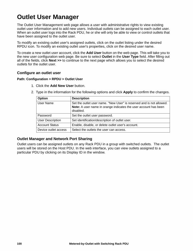
Outlet User ManagerThe Outlet User Management web page allows a user with administrative rights to view existing outlet user information and to add new users. Individual outlets can be assigned to each outlet user. When an outlet user logs into the Rack PDU, he or she will only be able to view or control outlets that have been assigned to the outlet user.
To modify an existing outlet user's assigned outlets, click on the outlet listing under the desired RPDU icon. To modify an existing outlet user's properties, click on the desired user name.
To create a new outlet user account, click the Add User button on the web page. This will take you to the new user configuration web page. Be sure to select Outlet in the User Type field. After filling out all of the fields, click Next >> to continue to the next page which allows you to select the desired outlets for the outlet user.
Configure an outlet user
Path: Configuration > RPDU > Outlet User
1. Click the Add New User button.
2. Type in the information for the following options and click Apply to confirm the changes.
Outlet Manager and Network Port SharingOutlet users can be assigned outlets on any Rack PDU in a group with switched outlets. The outlet users will be stored on the Host PDU. In the web interface, you can view outlets assigned to a particular PDU by clicking on its Display ID in the window.
Option Description
User Name Set the outlet user name. "New User" is reserved and is not allowed.Note: A user name in orange indicates the user account has been disabled.
Password Set the outlet user password.
User Description Set identification/description of outlet user.
Account Status Enable, disable, or delete outlet user's account.
Device outlet access Select the outlets the user can access.
Metered-by-Outlet with Switching Rack PDU100
Configure Temperature and Humidity SensorsPath: Configuration > RPDU > Environment
Note: To use this feature, you must have installed an optional Schneider Electric Temperature Sensor (AP9335T) or Schneider Electric Temperature/Humidity Sensor (AP9335TH) to your Rack PDU.
For temperature:• If the high temperature threshold is reached, the system generates a Warning alarm.• If the maximum temperature threshold is reached, the system generates a Critical alarm.
Similarly, for humidity:• If the low humidity threshold is reached, the system generates a Warning alarm.• If the minimum humidity threshold is reached, the system generates a Critical alarm.
Note: Click the thermometer symbol in the upper right corner to toggle between Fahrenheit and Celsius.
To configure temperature and humidity sensors:
1. Enter values for minimum, maximum, high, and low thresholds.
2. Enter Hysteresis values.
3. Enable alarm generation as desired.
4. Click Apply.
HysteresisThis value specifies how far past a threshold the temperature or humidity must return to clear a threshold violation.
• For Maximum and High temperature threshold violations, the clearing point is the threshold minus the hysteresis.
• For Minimum and Low humidity threshold violations, the clearing point is the threshold plus the hysteresis.
Increase the value for Temperature Hysteresis or Humidity Hysteresis to avoid multiple alarms if temperature or humidity that has caused a violation then wavers slightly up and down. If the hysteresis value is too low, such wavering can cause and clear a threshold violation repeatedly.
Example of rising but wavering temperature: The maximum temperature threshold is 85°F, and the temperature hysteresis is 3°F. The temperature rises above 85°F, violating the threshold. It then wavers down to 84°F and then up to 86°F repeatedly, but no clearing event and no new violation occur. For the existing violation to clear, the temperature would have to drop to 82°F (3°F below the threshold).
Example of falling but wavering humidity: The minimum humidity threshold is 18%, and the humidity hysteresis is 8%. The humidity falls below 18%, violating the threshold. It then wavers up to 24% and down to 13% repeatedly, but no clearing event and no new violation occur. For the existing violation to clear, the humidity would have to rise to above 26% (8% past the threshold).
101Metered-by-Outlet with Switching Rack PDU
SecuritySession Management screen
Path: Configuration > Security > Session Management
Enabling Allow Concurrent Logins means that two or more users can log on at the same time. Each user has equal access and each interface (HTTP, FTP, telnet console, serial console (CLI), etc.) counts as a logged-in user.
Remote Authentication Override: The Rack PDU supports Radius storage of passwords on a server. However, if you enable this override, the Rack PDU will allow a local user to log on using the password for the Rack PDU that is stored locally on the Rack PDU. See also “Local Users” and “Remote Users authentication”.
Ping Response
Path: Configuration > Security > Ping Response
Select the Enable check box for IPv4 Ping Response to allow the Rack PDU to respond to network pings. Clear the check box to disable an Rack PDU response. This does not apply to IPv6.
Local Users
Use These menu options to view, and to set up access and individual preferences (like displayed date format), to the Rack PDU user interfaces. This applies to users as defined by their logon name.
Path: Configuration > Security > Local Users > Management
Setting user access With this option an Administrator or Super User can list and configure the users allowed access to the UI. The Super User user account always has access to the Rack PDU.
Click on Add User to add a user. On the resulting User Configuration screen, you can add a user and withhold access by clearing the Access check box. User names and passwords are case-sensitive. The maximum length for both the name and password is 64 bytes, with less for multi-byte characters. You have to enter a password. Blank passwords, (passwords with no characters) are not allowed.
Note: Values greater than 64 bytes in Name and Password might get truncated. To change an Administrator/Super User setting, you must enter all three password fields.
Use Session Timeout to configure the time (3 minutes by default) that the UI waits before logging off an inactive user. If you change this value, you must log off for the change to take effect.
Note: This timer continues to run if a user closes the browser window without first logging Off by clicking Log Off at the upper right.Because that user is still considered to be logged on, no user can log on until the time specified as Minutes of Inactivity expires. For example, with the default value for Minutes of Inactivity, if a user closes the browser window without logging off, no user can log on for 3 minutes.
Serial Remote Authentication OverrideBy selecting this option, you can bypass RADIUS by using the serial console (CLI) connection. This screen enables it for the selected user, but it must also be enabled globally to work, (through the “Session Management” screen).
Default settingsDetermine the default values to populate in each of the fields when the Super User or Administrator-level account creates a new user. These values can be changed before the settings are applied to the system.
• Access: Put a check in the Enable box to allow access.
• User Type: Select the user type from the dropdown menu.
• User Description: Type the user Description in the box.
• Session Timeout: Select from 1 to 60 seconds.
• Bad Login Attempts. Set the number of failed login attempts the user can have. Select from 0 to 99 attempts. 0= unlimited.
Metered-by-Outlet with Switching Rack PDU102
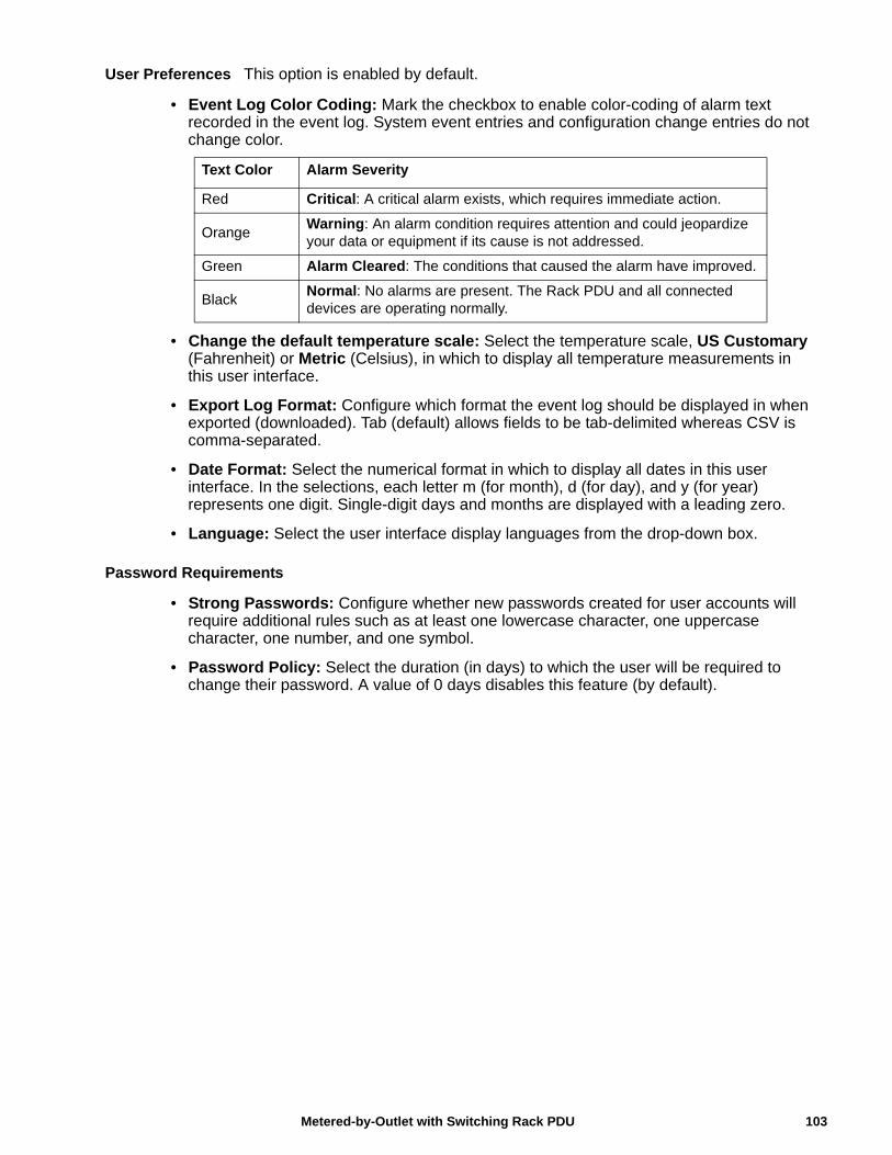
User Preferences This option is enabled by default.
• Event Log Color Coding: Mark the checkbox to enable color-coding of alarm text recorded in the event log. System event entries and configuration change entries do not change color.
• Change the default temperature scale: Select the temperature scale, US Customary (Fahrenheit) or Metric (Celsius), in which to display all temperature measurements in this user interface.
• Export Log Format: Configure which format the event log should be displayed in when exported (downloaded). Tab (default) allows fields to be tab-delimited whereas CSV is comma-separated.
• Date Format: Select the numerical format in which to display all dates in this user interface. In the selections, each letter m (for month), d (for day), and y (for year) represents one digit. Single-digit days and months are displayed with a leading zero.
• Language: Select the user interface display languages from the drop-down box.
Password Requirements
• Strong Passwords: Configure whether new passwords created for user accounts will require additional rules such as at least one lowercase character, one uppercase character, one number, and one symbol.
• Password Policy: Select the duration (in days) to which the user will be required to change their password. A value of 0 days disables this feature (by default).
Text Color Alarm Severity
Red Critical: A critical alarm exists, which requires immediate action.
OrangeWarning: An alarm condition requires attention and could jeopardize your data or equipment if its cause is not addressed.
Green Alarm Cleared: The conditions that caused the alarm have improved.
BlackNormal: No alarms are present. The Rack PDU and all connected devices are operating normally.
103Metered-by-Outlet with Switching Rack PDU
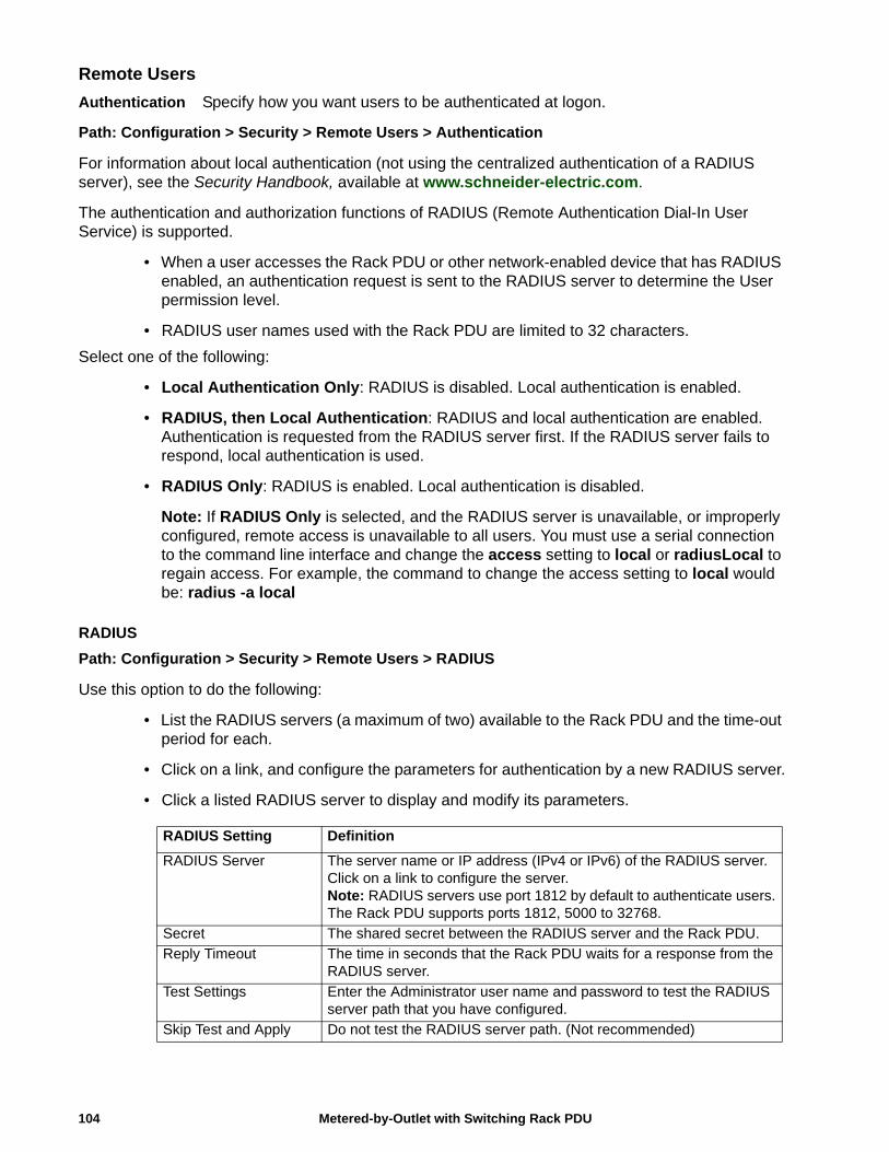
Remote Users
Authentication Specify how you want users to be authenticated at logon.
Path: Configuration > Security > Remote Users > Authentication
For information about local authentication (not using the centralized authentication of a RADIUS server), see the Security Handbook, available at www.schneider-electric.com.
The authentication and authorization functions of RADIUS (Remote Authentication Dial-In User Service) is supported.
• When a user accesses the Rack PDU or other network-enabled device that has RADIUS enabled, an authentication request is sent to the RADIUS server to determine the User permission level.
• RADIUS user names used with the Rack PDU are limited to 32 characters.
Select one of the following:
• Local Authentication Only: RADIUS is disabled. Local authentication is enabled.
• RADIUS, then Local Authentication: RADIUS and local authentication are enabled. Authentication is requested from the RADIUS server first. If the RADIUS server fails to respond, local authentication is used.
• RADIUS Only: RADIUS is enabled. Local authentication is disabled.
Note: If RADIUS Only is selected, and the RADIUS server is unavailable, or improperly configured, remote access is unavailable to all users. You must use a serial connection to the command line interface and change the access setting to local or radiusLocal to regain access. For example, the command to change the access setting to local would be: radius -a local
RADIUS
Path: Configuration > Security > Remote Users > RADIUS
Use this option to do the following:
• List the RADIUS servers (a maximum of two) available to the Rack PDU and the time-out period for each.
• Click on a link, and configure the parameters for authentication by a new RADIUS server.
• Click a listed RADIUS server to display and modify its parameters.
RADIUS Setting Definition
RADIUS Server The server name or IP address (IPv4 or IPv6) of the RADIUS server. Click on a link to configure the server.Note: RADIUS servers use port 1812 by default to authenticate users. The Rack PDU supports ports 1812, 5000 to 32768.
Secret The shared secret between the RADIUS server and the Rack PDU.
Reply Timeout The time in seconds that the Rack PDU waits for a response from the RADIUS server.
Test Settings Enter the Administrator user name and password to test the RADIUS server path that you have configured.
Skip Test and Apply Do not test the RADIUS server path. (Not recommended)
Metered-by-Outlet with Switching Rack PDU104
105Metered-by-Outlet with Switching Rack PDU
Configure the RADIUS Server
Summary of the configuration procedure
You must configure your RADIUS server to work with the Rack PDU.
For examples of the RADIUS users file with Vendor Specific Attributes (VSAs) and an example of an entry in the dictionary file on the RADIUS server, see the Security Handbook.
1. Add the IP address of the Rack PDU to the RADIUS server client list (file).
2. Users must be configured with Service-Type attributes unless Vendor Specific Attributes (VSAs) are defined. If no Service-Type attributes are configured, users will have read-only access (on the Web interface only).
See your RADIUS server documentation for information about the RADIUS users file, and see the Security Handbook for an example.
3. VSAs can be used instead of the Service-Type attributes provided by the RADIUS server. VSAs require a dictionary entry and a RADIUS users file. In the dictionary file, define the names for the ATTRIBUTE and VALUE keywords, but not for the numeric values. If you change numeric values, RADIUS authentication and authorization will fail. VSAs take precedence over standard RADIUS attributes.
Configuring a RADIUS server on UNIX® with shadow passwords
If UNIX shadow password files are used (/etc/passwd) with the RADIUS dictionary files, the following two methods can be used to authenticate users:
• If all UNIX users have administrative privileges, add the following to the RADIUS “user” file. To allow only Device Users, change the APC-Service-Type to Device.
DEFAULT Auth-Type = SystemAPC-Service-Type = Admin
• Add user names and attributes to the RADIUS “user” file, and verify the password against /etc/passwd. The following example is for users bconners and thawk:
bconners Auth-Type = SystemAPC-Service-Type = Admin
thawk Auth-Type = SystemAPC-Service-Type = Device
Supported RADIUS servers
FreeRADIUS and Microsoft IAS 2003 are supported. Other commonly available RADIUS applications may work but have not been fully tested.
RADIUS and Network Port Sharing
Note: See the Security Handbook for Network Management Cards for more information on using RADIUS.
For RADIUS users file with VSAs, outlets on guest Rack PDUs can be associated to RADIUS users by using the following method:
# give user access to outlets 1, 2, and 3 on unit 1,# outlet 7 on unit 2, outlets 1 through 6# on unit 3, and outlets 1,2,4 through 6, 7 through 10,# and 20 on unit 4newOutletUser Auth-Type = Local, User-Password = "newoutlets"APC-Service-Type = Outlet,APC-Outlets = "1[1,2,3];2[7];3[1-6];4[1,2,4-6,7-10,20];"
Firewall Menus
Path: Configuration > Security > Firewall
Configuration Enable or disable the overall firewall functionality. Any configured policy is also listed, even if the firewall is disabled.
Active Policy Select an active policy from the available firewall policies. The validity of policy is also listed here.
Active Rules When a firewall is enabled, this lists the individual rules that are being enforced by a current active policy. You can edit existing rules and add or delete new rules here.
Create/Edit Policy Create a new policy or edit an existing one.
Load Policy Load a policy (with .fwl suffix) from a source external to this device.
Test Temporarily enforce the rules of a chosen policy for a time that you specify.
Metered-by-Outlet with Switching Rack PDU106
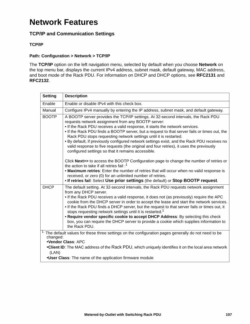
Network FeaturesTCP/IP and Communication Settings
TCP/IP
Path: Configuration > Network > TCP/IP
The TCP/IP option on the left navigation menu, selected by default when you choose Network on the top menu bar, displays the current IPv4 address, subnet mask, default gateway, MAC address, and boot mode of the Rack PDU. For information on DHCP and DHCP options, see RFC2131 and RFC2132.
Setting Description
Enable Enable or disable IPv4 with this check box.
Manual Configure IPv4 manually by entering the IP address, subnet mask, and default gateway.
BOOTP A BOOTP server provides the TCP/IP settings. At 32-second intervals, the Rack PDU requests network assignment from any BOOTP server:• If the Rack PDU receives a valid response, it starts the network services.• If the Rack PDU finds a BOOTP server, but a request to that server fails or times out, the
Rack PDU stops requesting network settings until it is restarted.• By default, if previously configured network settings exist, and the Rack PDU receives no
valid response to five requests (the original and four retries), it uses the previously configured settings so that it remains accessible.
Click Next>> to access the BOOTP Configuration page to change the number of retries or the action to take if all retries fail :1
• Maximum retries: Enter the number of retries that will occur when no valid response is received, or zero (0) for an unlimited number of retries.
• If retries fail: Select Use prior settings (the default) or Stop BOOTP request.
DHCP The default setting. At 32-second intervals, the Rack PDU requests network assignment from any DHCP server.• If the Rack PDU receives a valid response, it does not (as previously) require the APC
cookie from the DHCP server in order to accept the lease and start the network services.• If the Rack PDU finds a DHCP server, but the request to that server fails or times out, it
stops requesting network settings until it is restarted.1
• Require vendor specific cookie to accept DHCP Address: By selecting this check box, you can require the DHCP server to provide a cookie which supplies information to the Rack PDU.
1. The default values for these three settings on the configuration pages generally do not need to be changed: •Vendor Class: APC•Client ID: The MAC address of the Rack PDU, which uniquely identifies it on the local area network
(LAN)•User Class: The name of the application firmware module
107Metered-by-Outlet with Switching Rack PDU
DHCP response options
Each valid DHCP response contains options that provide the TCP/IP settings that the Rack PDU needs to operate on a network, and other information that affects the operation of the Rack PDU.
Vendor Specific Information (option 43) The Rack PDU uses this option in a DHCP response to determine whether the DHCP response is valid. This option contains an APC-specific option in a TAG/LEN/DATA format, called the APC Cookie. This is disabled by default.
• APC Cookie. Tag 1, Len 4, Data “1APC”
Option 43 communicates to the Rack PDU that a DHCP server is configured to service devices.
Following, in hexadecimal format, is an example of a Vendor Specific Information option that contains the APC cookie:
Option 43 = 0x01 0x04 0x31 0x41 0x50 0x43
TCP/IP options The Rack PDU uses the following options within a valid DHCP response to define its TCP/IP settings. All of these options except the first are described in RFC2132.
• IP Address (from the yiaddr field of the DHCP response, described in RFC2131): The IP address that the DHCP server is leasing to the Rack PDU.
• Subnet Mask (option 1): The Subnet Mask value that the Rack PDU needs to operate on the network.
• Router, i.e., Default Gateway (option 3): The default gateway address that the Rack PDU needs to operate on the network.
• IP Address Lease Time (option 51): The time duration for the lease of the IP Address to the Rack PDU.
• Renewal Time, T1 (option 58): The time that the Rack PDU must wait after an IP address lease is assigned before it can request a renewal of that lease.
• Rebinding Time, T2 (option 59): The time that the Rack PDU must wait after an IP address lease is assigned before it can seek to rebind that lease.
Other options The Rack PDU also uses these options within a valid DHCP response. All of these options except the last are described in RFC2132.
• Network Time Protocol Servers (option 42): Up to two NTP servers (primary and secondary) that the Rack PDU can use.
• Time Offset (option 2): The offset of the Rack PDU's subnet, in seconds, from Coordinated Universal Time (UTC).
• Domain Name Server (option 6): Up to two Domain Name System (DNS) servers (primary and secondary) that the Rack PDU can use.
• Host Name (option 12): The host name that the Rack PDU will use (32-character maximum length).
• Domain Name (option 15): The domain name that the Rack PDU will use (64-character maximum length).
• Boot File Name (from the file field of the DHCP response, described in RFC2131): The fully qualified directory-path to a user configuration file (.ini file) to download. The siaddr field of the DHCP response specifies the IP address of the server from which the Rack PDU will download the .ini file. After the download, the .ini file is used as a boot file to reconfigure the settings.
Metered-by-Outlet with Switching Rack PDU108
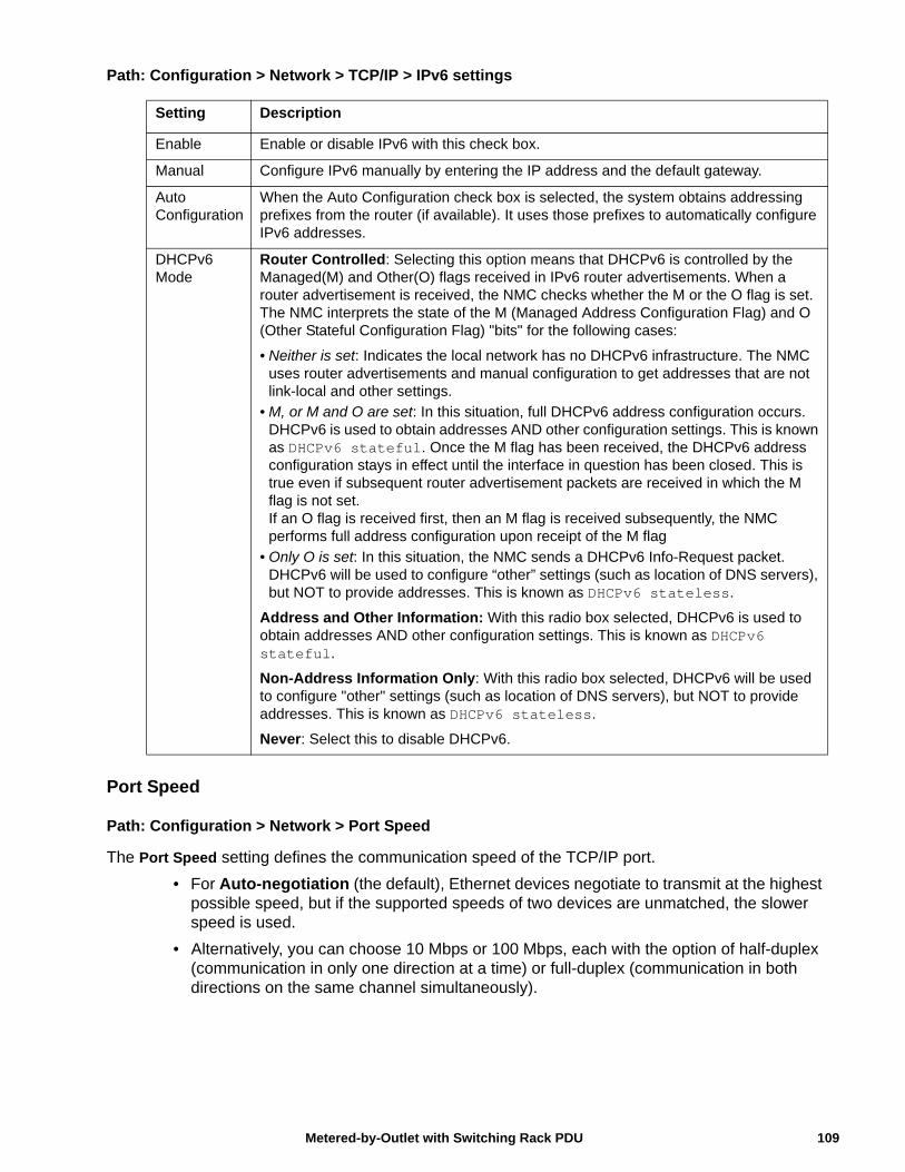
Path: Configuration > Network > TCP/IP > IPv6 settings
Port Speed
Path: Configuration > Network > Port Speed
The Port Speed setting defines the communication speed of the TCP/IP port.
• For Auto-negotiation (the default), Ethernet devices negotiate to transmit at the highest possible speed, but if the supported speeds of two devices are unmatched, the slower speed is used.
• Alternatively, you can choose 10 Mbps or 100 Mbps, each with the option of half-duplex (communication in only one direction at a time) or full-duplex (communication in both directions on the same channel simultaneously).
Setting Description
Enable Enable or disable IPv6 with this check box.
Manual Configure IPv6 manually by entering the IP address and the default gateway.
Auto Configuration
When the Auto Configuration check box is selected, the system obtains addressing prefixes from the router (if available). It uses those prefixes to automatically configure IPv6 addresses.
DHCPv6 Mode
Router Controlled: Selecting this option means that DHCPv6 is controlled by the Managed(M) and Other(O) flags received in IPv6 router advertisements. When a router advertisement is received, the NMC checks whether the M or the O flag is set. The NMC interprets the state of the M (Managed Address Configuration Flag) and O (Other Stateful Configuration Flag) "bits" for the following cases:
• Neither is set: Indicates the local network has no DHCPv6 infrastructure. The NMC uses router advertisements and manual configuration to get addresses that are not link-local and other settings.
• M, or M and O are set: In this situation, full DHCPv6 address configuration occurs. DHCPv6 is used to obtain addresses AND other configuration settings. This is known as DHCPv6 stateful. Once the M flag has been received, the DHCPv6 address configuration stays in effect until the interface in question has been closed. This is true even if subsequent router advertisement packets are received in which the M flag is not set.If an O flag is received first, then an M flag is received subsequently, the NMC performs full address configuration upon receipt of the M flag
• Only O is set: In this situation, the NMC sends a DHCPv6 Info-Request packet. DHCPv6 will be used to configure “other” settings (such as location of DNS servers), but NOT to provide addresses. This is known as DHCPv6 stateless.
Address and Other Information: With this radio box selected, DHCPv6 is used to obtain addresses AND other configuration settings. This is known as DHCPv6 stateful.
Non-Address Information Only: With this radio box selected, DHCPv6 will be used to configure "other" settings (such as location of DNS servers), but NOT to provide addresses. This is known as DHCPv6 stateless.
Never: Select this to disable DHCPv6.
109Metered-by-Outlet with Switching Rack PDU
DNS
Path: Configuration > Network > DNS > Configuration
Use the options under Configuration to configure and test the Domain Name System (DNS):
• Override Manual DNS Settings: Selection of Override Manual DNS Settings will result in configuration data from other sources (typically DHCP) taking precedence over the manual configurations set here.
• Select Primary DNS Server or Secondary DNS Server to specify the IPv4 or IPv6 addresses of the primary and optional secondary DNS server. For the Rack PDU to send e-mail, you must at least define the IP address of the primary DNS server.
– The Rack PDU waits up to 15 seconds for a response from the primary DNS server or secondary DNS server (if specified). If the Rack PDU does not receive a response within that time, e-mail cannot be sent. Use DNS servers on the same segment as the Rack PDU or on a nearby segment (but not across a wide-area network [WAN]).
– Define the IP addresses of the DNS servers then enter the DNS name of a computer on your network to look up the IP address for that computer to verify correct operation.
• System Name Synchronization: Allow the system name to be synchronized with the host name so both fields automatically contain the same value. Note: When enabling this feature, the system name identifier can no longer contain a space character (since it will be synchronized to the host name field).
• Host Name: Configure a host name here and a domain name in the Domain Name field then users can enter a host name in any field in the NMC interface (except e-mail addresses) that accepts a domain name.
• Domain Name (IPv4/IPv6): Configure the domain name here only. In all other fields in the NMC interface (except e-mail addresses) that accept domain names, the Rack PDU adds this domain name when only a host name is entered.
– To override all instances of the expansion of a specified host name by the addition of the domain name, set the domain name field to its default, somedomain.com, or to 0.0.0.0.
– To override the expansion of a specific host name entry, include a trailing period. The NMC recognizes a host name with a trailing period (such as mySnmpServer.) as if it were a fully-qualified domain name and does not append the domain name.
• Domain Name (IPv6): Specify the IPv6 domain name here.
Metered-by-Outlet with Switching Rack PDU110
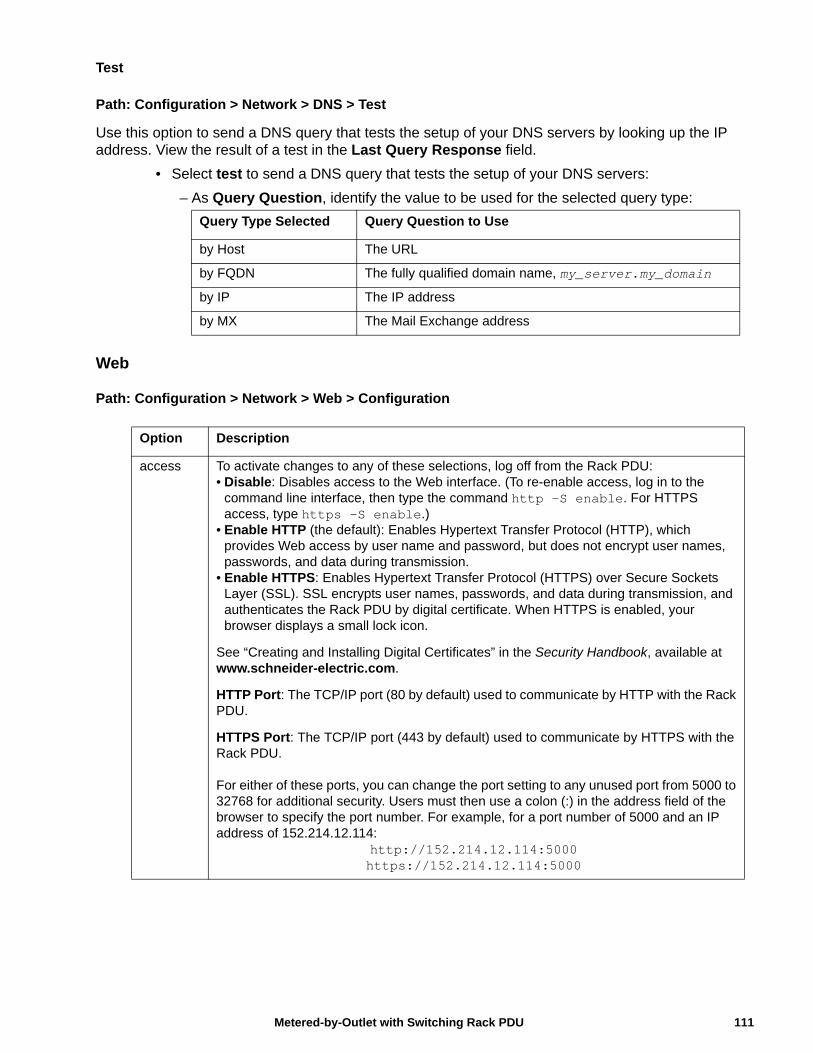
Test
Path: Configuration > Network > DNS > Test
Use this option to send a DNS query that tests the setup of your DNS servers by looking up the IP address. View the result of a test in the Last Query Response field.
• Select test to send a DNS query that tests the setup of your DNS servers:
– As Query Question, identify the value to be used for the selected query type:
Web
Path: Configuration > Network > Web > Configuration
Query Type Selected Query Question to Use
by Host The URL
by FQDN The fully qualified domain name, my_server.my_domain
by IP The IP address
by MX The Mail Exchange address
Option Description
access To activate changes to any of these selections, log off from the Rack PDU:• Disable: Disables access to the Web interface. (To re-enable access, log in to the
command line interface, then type the command http -S enable. For HTTPS access, type https -S enable.)
• Enable HTTP (the default): Enables Hypertext Transfer Protocol (HTTP), which provides Web access by user name and password, but does not encrypt user names, passwords, and data during transmission.
• Enable HTTPS: Enables Hypertext Transfer Protocol (HTTPS) over Secure Sockets Layer (SSL). SSL encrypts user names, passwords, and data during transmission, and authenticates the Rack PDU by digital certificate. When HTTPS is enabled, your browser displays a small lock icon.
See “Creating and Installing Digital Certificates” in the Security Handbook, available at www.schneider-electric.com.
HTTP Port: The TCP/IP port (80 by default) used to communicate by HTTP with the Rack PDU.
HTTPS Port: The TCP/IP port (443 by default) used to communicate by HTTPS with the Rack PDU.
For either of these ports, you can change the port setting to any unused port from 5000 to 32768 for additional security. Users must then use a colon (:) in the address field of the browser to specify the port number. For example, for a port number of 5000 and an IP address of 152.214.12.114:
http://152.214.12.114:5000https://152.214.12.114:5000
111Metered-by-Outlet with Switching Rack PDU
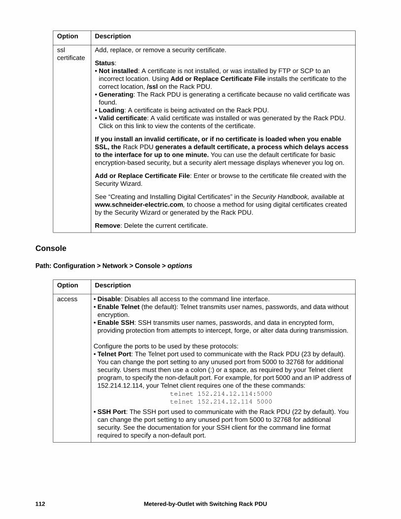
Console
Path: Configuration > Network > Console > options
ssl certificate
Add, replace, or remove a security certificate.
Status:• Not installed: A certificate is not installed, or was installed by FTP or SCP to an
incorrect location. Using Add or Replace Certificate File installs the certificate to the correct location, /ssl on the Rack PDU.
• Generating: The Rack PDU is generating a certificate because no valid certificate was found.
• Loading: A certificate is being activated on the Rack PDU.• Valid certificate: A valid certificate was installed or was generated by the Rack PDU.
Click on this link to view the contents of the certificate.
If you install an invalid certificate, or if no certificate is loaded when you enable SSL, the Rack PDU generates a default certificate, a process which delays access to the interface for up to one minute. You can use the default certificate for basic encryption-based security, but a security alert message displays whenever you log on.
Add or Replace Certificate File: Enter or browse to the certificate file created with the Security Wizard.
See “Creating and Installing Digital Certificates” in the Security Handbook, available at www.schneider-electric.com, to choose a method for using digital certificates created by the Security Wizard or generated by the Rack PDU.
Remove: Delete the current certificate.
Option Description
access • Disable: Disables all access to the command line interface.• Enable Telnet (the default): Telnet transmits user names, passwords, and data without
encryption.• Enable SSH: SSH transmits user names, passwords, and data in encrypted form,
providing protection from attempts to intercept, forge, or alter data during transmission.
Configure the ports to be used by these protocols: • Telnet Port: The Telnet port used to communicate with the Rack PDU (23 by default).
You can change the port setting to any unused port from 5000 to 32768 for additional security. Users must then use a colon (:) or a space, as required by your Telnet client program, to specify the non-default port. For example, for port 5000 and an IP address of 152.214.12.114, your Telnet client requires one of the these commands:
telnet 152.214.12.114:5000telnet 152.214.12.114 5000
• SSH Port: The SSH port used to communicate with the Rack PDU (22 by default). You can change the port setting to any unused port from 5000 to 32768 for additional security. See the documentation for your SSH client for the command line format required to specify a non-default port.
Option Description
Metered-by-Outlet with Switching Rack PDU112
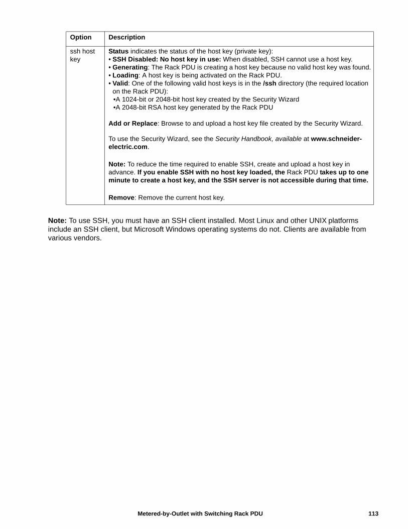
Note: To use SSH, you must have an SSH client installed. Most Linux and other UNIX platforms include an SSH client, but Microsoft Windows operating systems do not. Clients are available from various vendors.
ssh host key
Status indicates the status of the host key (private key):• SSH Disabled: No host key in use: When disabled, SSH cannot use a host key.• Generating: The Rack PDU is creating a host key because no valid host key was found.• Loading: A host key is being activated on the Rack PDU.• Valid: One of the following valid host keys is in the /ssh directory (the required location
on the Rack PDU): •A 1024-bit or 2048-bit host key created by the Security Wizard•A 2048-bit RSA host key generated by the Rack PDU
Add or Replace: Browse to and upload a host key file created by the Security Wizard.
To use the Security Wizard, see the Security Handbook, available at www.schneider-electric.com.
Note: To reduce the time required to enable SSH, create and upload a host key in advance. If you enable SSH with no host key loaded, the Rack PDU takes up to one minute to create a host key, and the SSH server is not accessible during that time.
Remove: Remove the current host key.
Option Description
113Metered-by-Outlet with Switching Rack PDU
SNMP
All user names, passwords, and community names for SNMP are transferred over the network as plain text. If your network requires the high security of encryption, disable SNMP access or set the access for each community to Read. (A community with Read access can receive status information and use SNMP traps.)
When using StruxureWare to manage a Rack PDU on the public network, you must have SNMP enabled in the Rack PDU interface. Read access will allow the StruxureWare to receive traps from the Rack PDU, but Write access is required while you use the interface of the Rack PDU to set the StruxureWare as a trap receiver.
For detailed information on enhancing and managing the security of your system, see the Security Handbook, available at www.schneider-electric.com.
Network Port Sharing
All Rack PDUs in a group can be accessed through the Host Rack PDU via SNMP "rPDU2" OIDs available in our PowerNet-MIB.
The full path to these OIDs is:
iso(1).org(3).dod(6).internet(1).private(4).enterprises(1).apc(318).products(1).hardware(1).rPDU2(26)
Individual Rack PDUs can be identified in the SNMP MIB tables by viewing the corresponding "Module" OIDs in each table. These Module OIDs will return the Display ID of the Rack PDU.
Example Module OIDs: rPDU2IdentModule, rPDU2DeviceConfigModule, rPDU2SensorTempHumidityConfigModule
In order to be backwards compatible with previous versions, the Host Rack PDU will always be the first index in any table that supports multiple Rack PDUs. In addition, after the Rack PDU group is set up, the index order of guest Rack PDUs should not change even if the Display ID is changed or a PDU temporarily loses communication. The index order should only change if you manually remove a Rack PDU from the group.
A MIB table walk should skip the indexes associated with a Rack PDU that has temporarily lost communication.
Metered-by-Outlet with Switching Rack PDU114
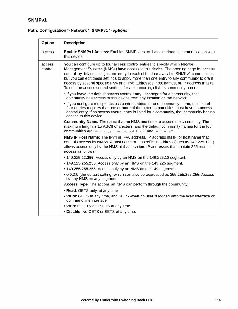
SNMPv1
Path: Configuration > Network > SNMPv1 > options
Option Description
access Enable SNMPv1 Access: Enables SNMP version 1 as a method of communication with this device.
access control
You can configure up to four access control entries to specify which Network Management Systems (NMSs) have access to this device. The opening page for access control, by default, assigns one entry to each of the four available SNMPv1 communities, but you can edit these settings to apply more than one entry to any community to grant access by several specific IPv4 and IPv6 addresses, host names, or IP address masks. To edit the access control settings for a community, click its community name.
• If you leave the default access control entry unchanged for a community, that community has access to this device from any location on the network.
• If you configure multiple access control entries for one community name, the limit of four entries requires that one or more of the other communities must have no access control entry. If no access control entry is listed for a community, that community has no access to this device.
Community Name: The name that an NMS must use to access the community. The maximum length is 15 ASCII characters, and the default community names for the four communities are public, private, public2, and private2.
NMS IP/Host Name: The IPv4 or IPv6 address, IP address mask, or host name that controls access by NMSs. A host name or a specific IP address (such as 149.225.12.1) allows access only by the NMS at that location. IP addresses that contain 255 restrict access as follows:
• 149.225.12.255: Access only by an NMS on the 149.225.12 segment.
• 149.225.255.255: Access only by an NMS on the 149.225 segment.
• 149.255.255.255: Access only by an NMS on the 149 segment.
• 0.0.0.0 (the default setting) which can also be expressed as 255.255.255.255: Access by any NMS on any segment.
Access Type: The actions an NMS can perform through the community.
• Read: GETS only, at any time
• Write: GETS at any time, and SETS when no user is logged onto the Web interface or command line interface.
• Write+: GETS and SETS at any time.
• Disable: No GETS or SETS at any time.
115Metered-by-Outlet with Switching Rack PDU
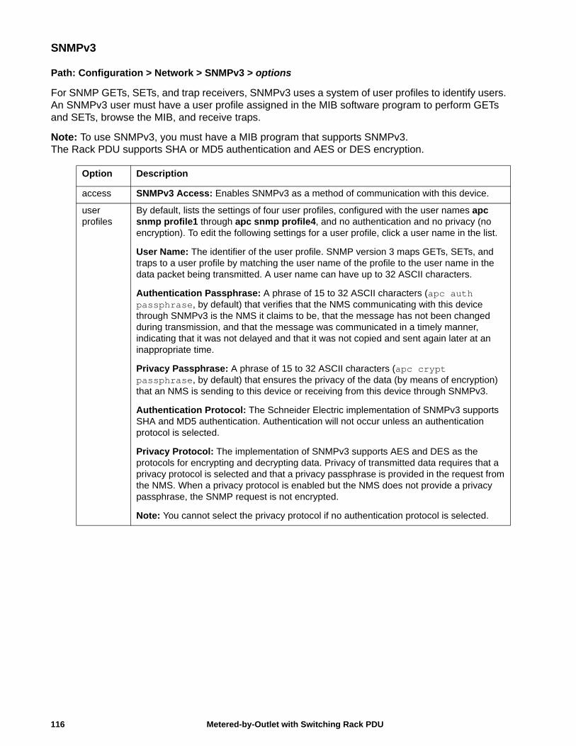
SNMPv3
Path: Configuration > Network > SNMPv3 > options
For SNMP GETs, SETs, and trap receivers, SNMPv3 uses a system of user profiles to identify users. An SNMPv3 user must have a user profile assigned in the MIB software program to perform GETs and SETs, browse the MIB, and receive traps.
Note: To use SNMPv3, you must have a MIB program that supports SNMPv3. The Rack PDU supports SHA or MD5 authentication and AES or DES encryption.
Option Description
access SNMPv3 Access: Enables SNMPv3 as a method of communication with this device.
user profiles
By default, lists the settings of four user profiles, configured with the user names apc snmp profile1 through apc snmp profile4, and no authentication and no privacy (no encryption). To edit the following settings for a user profile, click a user name in the list.
User Name: The identifier of the user profile. SNMP version 3 maps GETs, SETs, and traps to a user profile by matching the user name of the profile to the user name in the data packet being transmitted. A user name can have up to 32 ASCII characters.
Authentication Passphrase: A phrase of 15 to 32 ASCII characters (apc auth passphrase, by default) that verifies that the NMS communicating with this device through SNMPv3 is the NMS it claims to be, that the message has not been changed during transmission, and that the message was communicated in a timely manner, indicating that it was not delayed and that it was not copied and sent again later at an inappropriate time.
Privacy Passphrase: A phrase of 15 to 32 ASCII characters (apc crypt passphrase, by default) that ensures the privacy of the data (by means of encryption) that an NMS is sending to this device or receiving from this device through SNMPv3.
Authentication Protocol: The Schneider Electric implementation of SNMPv3 supports SHA and MD5 authentication. Authentication will not occur unless an authentication protocol is selected.
Privacy Protocol: The implementation of SNMPv3 supports AES and DES as the protocols for encrypting and decrypting data. Privacy of transmitted data requires that a privacy protocol is selected and that a privacy passphrase is provided in the request from the NMS. When a privacy protocol is enabled but the NMS does not provide a privacy passphrase, the SNMP request is not encrypted.
Note: You cannot select the privacy protocol if no authentication protocol is selected.
Metered-by-Outlet with Switching Rack PDU116
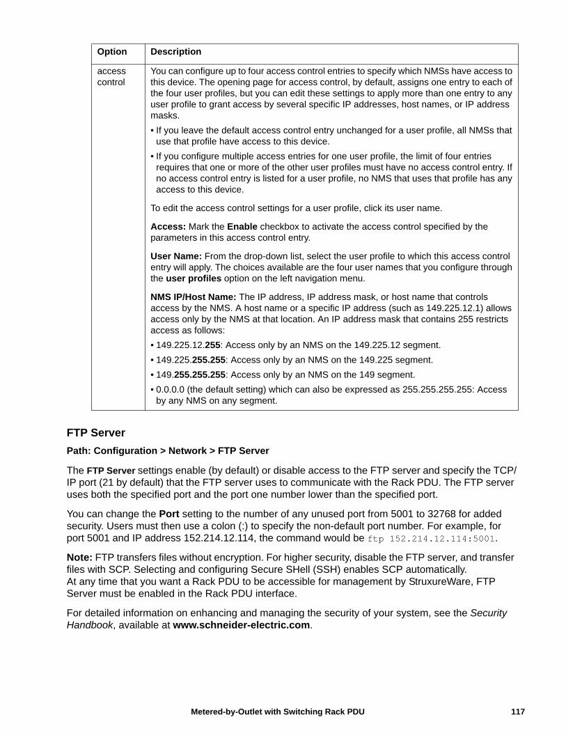
FTP Server
Path: Configuration > Network > FTP Server
The FTP Server settings enable (by default) or disable access to the FTP server and specify the TCP/IP port (21 by default) that the FTP server uses to communicate with the Rack PDU. The FTP server uses both the specified port and the port one number lower than the specified port.
You can change the Port setting to the number of any unused port from 5001 to 32768 for added security. Users must then use a colon (:) to specify the non-default port number. For example, for port 5001 and IP address 152.214.12.114, the command would be ftp 152.214.12.114:5001.
Note: FTP transfers files without encryption. For higher security, disable the FTP server, and transfer files with SCP. Selecting and configuring Secure SHell (SSH) enables SCP automatically.At any time that you want a Rack PDU to be accessible for management by StruxureWare, FTP Server must be enabled in the Rack PDU interface.
For detailed information on enhancing and managing the security of your system, see the Security Handbook, available at www.schneider-electric.com.
access control
You can configure up to four access control entries to specify which NMSs have access to this device. The opening page for access control, by default, assigns one entry to each of the four user profiles, but you can edit these settings to apply more than one entry to any user profile to grant access by several specific IP addresses, host names, or IP address masks.
• If you leave the default access control entry unchanged for a user profile, all NMSs that use that profile have access to this device.
• If you configure multiple access entries for one user profile, the limit of four entries requires that one or more of the other user profiles must have no access control entry. If no access control entry is listed for a user profile, no NMS that uses that profile has any access to this device.
To edit the access control settings for a user profile, click its user name.
Access: Mark the Enable checkbox to activate the access control specified by the parameters in this access control entry.
User Name: From the drop-down list, select the user profile to which this access control entry will apply. The choices available are the four user names that you configure through the user profiles option on the left navigation menu.
NMS IP/Host Name: The IP address, IP address mask, or host name that controls access by the NMS. A host name or a specific IP address (such as 149.225.12.1) allows access only by the NMS at that location. An IP address mask that contains 255 restricts access as follows:
• 149.225.12.255: Access only by an NMS on the 149.225.12 segment.
• 149.225.255.255: Access only by an NMS on the 149.225 segment.
• 149.255.255.255: Access only by an NMS on the 149 segment.
• 0.0.0.0 (the default setting) which can also be expressed as 255.255.255.255: Access by any NMS on any segment.
Option Description
117Metered-by-Outlet with Switching Rack PDU
NotificationsEvent Actions
Path: Configuration > Notification
Types of notification
You can configure event actions to occur in response to an event or group of events. These actions notify users of the event in any of several ways:
• Active, automatic notification. The specified users or monitoring devices are contacted directly.
– E-mail notification
– SNMP traps
– Remote Monitoring Service
– Syslog notification
• Indirect notification
– Event log. If no direct notification is configured, users must check the log to determine which events have occurred
You can also log system performance data to use for device monitoring. See “Logs in the Configuration Menu” on page 127 for information on how to configure and use this data logging option.
– Queries (SNMP GETs)
For more information, see “SNMP” on page 114. SNMP enables an NMS to perform informational queries. For SNMPv1, which does not encrypt data before transmission, configuring the most restrictive SNMP access type (READ) enables informational queries without the risk of allowing remote configuration changes.
Configure event actions
Path: Configuration > Notification > Event Actions > By Event
By default, logging an event is selected for all events. To define event actions for an individual event:
1. To find an event, click on a column heading to see the lists under the Device Events or System Events categories. Or you can click on a sub-category under these headings, like Security or Temperature.
2. Click on the event name to view or change the current configuration, such as recipients to be notified by e-mail, or Network Management Systems (NMSs) to be notified by SNMP traps. If no Syslog server is configured, items related to Syslog configuration are not displayed.
Note: When viewing details of an event configuration, you can enable or disable event logging or Syslog, or disable notification for specific e-mail recipients or trap receivers, but you cannot add or remove recipients or receivers. To add or remove recipients or receivers, see the following:
• “Identifying Syslog servers” on page 127
• “Path: Configuration > Notification > E-mail > Recipients” on page 121
• “Path: Configuration > Notification > SNMP Traps > Trap Receivers” on page 122
Metered-by-Outlet with Switching Rack PDU118
Path: Configuration > Notification > Event Actions > By Group
To configure a group of events simultaneously:
1. Select how to group events for configuration:
– Select Events by Severity, and then select one or more severity levels. You cannot change the severity of an event.
– Select Events by Category, and then select all events in one or more pre-defined categories.
2. Click Next to move to the next screen to do the following:
a. Select event actions for the group of events.
• To select any action except Logging (the default), you must first have at least one relevant recipient or receiver configured.
• If you selected Logging and have configured a Syslog server, select Event Log or Syslog on the next screen. See “Logs in the Configuration Menu” on page 127
3. Click Next to move to the next screen to do the following:
a. If you selected Logging on the previous screen, select Enable Notifications or Disable Notification.
b. If you selected Email Recipients on the previous screen, select the e-mail recipients to configure.
c. If you selected Trap Receivers on the previous screen, select the trap receiver to configure.
4. Click Next to move to the next screen to do the following:
a. If you are configuring Logging settings, view the pending actions and click Apply to accept the changes or click Cancel to revert to the previous settings.
b. If you are configuring Email Recipients or Trap Receivers, select Enable Notifications or Disable Notification and set the notification timing settings (see “Notification parameters” on page 120 for more information on these settings).
5. Click Next to move to the next screen to do the following:
a. View the pending actions and click Apply to accept the changes or click Cancel to revert to the previous settings.
119Metered-by-Outlet with Switching Rack PDU
Notification parameters. These configuration fields define e-mail parameters for sending notifications of events.
They are usually accessed by clicking the receiver or recipient name.
Note: For events that have an associated clearing event, you can also set these parameters.
E-mail notification screens
Use Simple Mail Transfer Protocol (SMTP) to send e-mail to up to four recipients when an event occurs. To use the e-mail feature, you must define the following settings:
• The IP addresses of the primary and, optionally, the secondary Domain Name System (DNS) servers.
• The IP address or DNS name for the SMTP Server and From Address.
• The e-mail addresses for a maximum of four recipients.
• You can use the To Address setting of the recipients option to send e-mail to a text-based screen.
Path: Configuration > Notification > E-mail > Server
This screen lists your primary and secondary DNS servers and displays the following fields:
From Address. The contents of the From field in e-mail messages sent by the RPDU:
• In the format user@ [IP_address] (if an IP address is specified as Local SMTP Server)
• In the format user@domain (if DNS is configured and the DNS name is specified as Local SMTP Server) in the e-mail messages.Note: The local SMTP server may require that you use a valid user account on the server for this setting. See the server documentation.
SMTP Server. The IPv4/ IPv6 address or DNS name of the local SMTP server.Note: This definition is required only when the SMTP server is set to Local.
Authentication. Enable this if the SMTP server requires authentication.
Port. The SMTP port number, with a default of 25. The range is 25, 465, 587, 5000 to 32768.
User Name, Password, and Confirm Password. If your mail server requires authentication, enter your user name and password here. This performs a simple authentication, not SSL.
Field Description
Delay n time before sending
If the event persists for the specified time, the notification is sent. If the condition clears before the time expires, no notification is sent.
Repeat at an interval of n The notification is sent repeatedly at the specified interval (the default is every 2 minutes until the condition clears).
Up to n times During an active event, the notification repeats for this number of times.
or
Until condition clears The notification is sent repeatedly until the condition clears or is resolved.
Metered-by-Outlet with Switching Rack PDU120
Use SSL/TLS. Select when encryption is used.
• Never: The SMTP server does not require nor support encryption.
• If Supported: The SMTP server advertises support for STARTTLS but doesn't require the connection to be encrypted. The STARTTLS command is sent after the advertisement is given.
• Always: The SMTP server requires the STARTTLS command to be sent on connection to it.
• Implicitly: The SMTP server only accepts connections that begin encrypted. No STARTTLS message is sent to the server.
Require CA Root Certificate. This should only be enabled if the security policy of your organization does not allow for implicit trust of SSL connections. If this is enabled, a valid root CA certificate must be loaded onto the RPDU for encrypted e-mails to be sent.
File Name. This field is dependent on the root CA certificates installed on the RPDU and whether or not a root CA certificate is required.
Path: Configuration > Notification > E-mail > Recipients
Specify up to four e-mail recipients. Click on a name to configure the settings.
Generation Enables (default) or disables sending e-mail to the recipient.
To Address The user and domain names of the recipient. To use e-mail for paging, use the e-mail address for the recipient’s pager gateway account (for example, [email protected]). The pager gateway will generate the page.
To bypass the DNS lookup of the IP address of the mail server, use the IP address in brackets instead of the e-mail domain name, e.g., use jsmith@[xxx.xxx.x.xxx] instead of [email protected]. This is useful when DNS lookups are not working correctly.
Language The language which the e-mail notification will be sent in. This is dependent on the installed language pack (if applicable).
Port The SMTP port number, with a default of 25. The range is 25, 465, 587, 5000 to 32768.
Format: The long format contains name, location, contact, IP address, serial number of the device, date and time, event code, and event description. The short format provides only the event description.
Server Select one of the following methods for routing e-mail:
• Local: This is through the site-local SMTP server. This recommended setting ensures that the e-mail is sent using the site-local SMTP server. Choosing this setting limits delays and network outages and retries sending e-mail for many hours. When choosing the Local setting you must also enable forwarding at the SMTP server of your device and set up a special external e-mail account to receive the forwarded e-mail. Check with your SMTP server administrator before making these changes.
• Recipient: This is the SMTP server of the recipient. The RPDU performs an MX record look-up on the recipients e-mail address and uses that as its SMTP server. The e-mail is only sent once so it could easily be lost.
• Custom: This setting enables each e-mail recipient to have its own server settings. These settings are independent of the settings given under “SMTP Server” above.
121Metered-by-Outlet with Switching Rack PDU
Path: Configuration > Notification > E-mail > SSL Certificates
Load a mail SSL certificate on the RPDU for greater security. The file must have an extension of .crt or .cer. Up to five files can be loaded at any given time.
When installed, the certificate details also display here. An invalid certificate will display “n/a” for all fields except File Name.
Certificates can be deleted using this screen. Any e-mail recipients using the certificate should be manually modified to remove reference to this certificate.
Path: Configuration > Notification > E-mail > Test
Send a test message to a configured recipient.
SNMP trap receiver screen
Path: Configuration > Notification > SNMP Traps > Trap Receivers
With Simple Network Management Protocol (SNMP) traps, you can automatically get notifications for significant RPDU events. They are a useful tool for monitoring devices on your network.
The trap receivers are displayed by NMS IP/Host Name, where NMS stands for Network Management System. You can configure up to six trap receivers.
To configure a new trap receiver, click Add Trap Receiver. To edit (or delete) one, click its IP address/host name.
Trap Generation. Enable (the default) or disable trap generation for this trap receiver.
NMS IP/Host Name. The IPv4/ IPv6 address or host name of this trap receiver. The default, 0.0.0.0, leaves the trap receiver undefined.
Language. Select a language from the drop-down list. This can differ from the UI and from other trap receivers.
Select either the SNMPv1 or SNMPv3 radio button to specify the trap type. For an NMS to receive both types of traps, you must separately configure two trap receivers for that NMS, one for each trap type.
SNMPv1. Settings for SNMPv1.
• Community Name: The name (“public” by default) used as an identifier when SNMPv1 traps are sent to this trap receiver.
• Authenticate Traps: When this option is enabled (the default), the NMS identified by the NMS IP/Host Name setting will receive authentication traps (traps generated by invalid attempts to log on to this device).
SNMPv3. Settings for SNMPv3.
• User Name: Select the identifier of the user profile for this trap receiver.
If you delete a trap receiver, all notification settings configured under “Configuring event actions” for the deleted trap receiver are set to their default values.
Metered-by-Outlet with Switching Rack PDU122
SNMP traps test screen
Path: Configuration > Notification > SNMP Traps > Test
Last Test Result. The result of the most recent SNMP trap test. A successful SNMP trap test verifies only that a trap was sent; it does not verify that the trap was received by the selected trap receiver. A trap test succeeds if all of the following are true:
• The SNMP version (SNMPv1 or SNMPv3) configured for the selected trap receiver is enabled on this device.
• The trap receiver itself is enabled.
• If a host name is selected for the To address, that host name can be mapped to a valid IP address.
To. Select the IP address or host name to which a test SNMP trap will be sent. If no trap receiver is configured, a link to the Trap Receiver configuration screen is displayed.
Remote Monitoring Service
Path: Configuration > Notification > Remote Monitoring
The remote monitoring service (RMS) is an optional service from Schneider Electric that monitors your system from a remote operation center 24 hours a day, 7 days a week, and notifies you of device and system events.
To purchase the RMS service, contact your vendor or click on the link on the top part of this screen: Schneider Electric RMS Web site.
Registration.To activate Schneider Electric RMS for the Rack PDU, select Enable Remote Monitoring Service., choose between Register Company and Device and Register Device Only, complete the form, and click Send APC RMS Registration.
Use the Reset Remote Monitoring Service Registration check box to discontinue the service, whether permanently or temporarily (for example, if you are moving a Rack PDU).
123Metered-by-Outlet with Switching Rack PDU
General MenuThis menu contains miscellaneous configuration items including device identification, date and time, exporting and importing your RPDU configuration options, the three links at the bottom left of the screen, and consolidating data for troubleshooting purposes.
Identification screen
Path: Configuration > General > Identification
Define the Name, the Location (the physical location), and the Contact (the person responsible for the device) used by:
• the SNMP agent of the RPDU and
• StruxureWare
Specifically, the name field is used by the sysName, sysContact, and sysLocation object identifiers (OIDs) in the SNMP agent of the Rack PDU. For more information about MIB-II OIDs, see the PowerNet® SNMP Management Information Base (MIB) Reference Guide, available at www.schneider-electric.com.
The Name and Location fields also identify the device when you register for the Remote Monitoring Service.
Host Name Synchronization allows the host name to be synchronized with the system name so both fields automatically contain the same value. Note: When enabling this feature, the system name identifier can no longer contain a space character (since it will be synchronized to the host name field).
System Message When defined, a custom message will appear on the log on screen for all users.
Date/Time screen
Path: Configuration > General > Date/Time > Mode
Set the time and date used by the RPDU. You can change the current settings manually or through a Network Time Protocol (NTP) Server:
With both, you select the Time Zone. This is your local time difference with Coordinated Universal Time (UTC), also known as Greenwich Mean Time (GMT).
Manual ModeDo one of the following:
• Enter the date and time for the RPDU
• Select the check box Apply Local Computer Time to apply the date and time settings of the computer you are using
Metered-by-Outlet with Switching Rack PDU124
Synchronize with NTP Server. Have an NTP (Network Time Protocol) Server define the date and time for the RPDU. By default, any RPDU on the private side of a StruxureWare obtains its time settings by using StruxureWare as an NTP server.
• Override Manual NTP Settings: If you select this, data from other sources (typically DHCP) take precedence over the NTP configurations you set here.
• Primary NTP Server: Enter the IP address or domain name of the primary NTP server.
• Secondary NTP Server: Enter the IP address or domain name of the secondary NTP server, when a secondary server is available.
• Update Interval: Define, in hours, how often the RPDU accesses the NTP Server for an update. Minimum: 1; Maximum: 8760 (1 year).
• Update Using NTP Now: Initiate an immediate update of the date and time by the NTP Server.
Daylight Saving
Path: Configuration > General > Date /Time > Daylight Saving
Daylight Saving Time (DST) is disabled by default. You can enable traditional United States DST, or enable and configure a customized daylight saving time to match how Daylight Saving Time is implemented in your local area.
When customizing DST, the system puts the clock forward by an hour when the time and date you specify under Start is reached and puts the clock back an hour when the time and date you specify under End is reached.
• If your local DST always starts or ends on the fourth occurrence of a specific weekday of a month (e.g., the fourth Sunday), choose Fourth/Last. If a fifth Sunday occurs in that month, you should still choose Fourth/Last.
• If your local DST always starts or ends on the last occurrence of a specific weekday of a month, whether it is the fourth or the fifth occurrence, choose Fifth/Last.
125Metered-by-Outlet with Switching Rack PDU
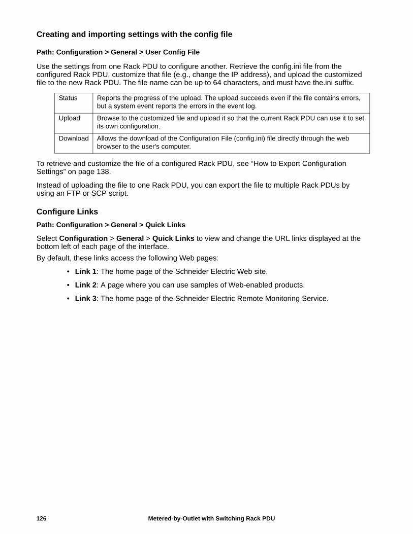
Creating and importing settings with the config file
Path: Configuration > General > User Config File
Use the settings from one Rack PDU to configure another. Retrieve the config.ini file from the configured Rack PDU, customize that file (e.g., change the IP address), and upload the customized file to the new Rack PDU. The file name can be up to 64 characters, and must have the.ini suffix.
To retrieve and customize the file of a configured Rack PDU, see “How to Export Configuration Settings” on page 138.
Instead of uploading the file to one Rack PDU, you can export the file to multiple Rack PDUs by using an FTP or SCP script.
Configure Links
Path: Configuration > General > Quick Links
Select Configuration > General > Quick Links to view and change the URL links displayed at the bottom left of each page of the interface.
By default, these links access the following Web pages:
• Link 1: The home page of the Schneider Electric Web site.
• Link 2: A page where you can use samples of Web-enabled products.
• Link 3: The home page of the Schneider Electric Remote Monitoring Service.
Status Reports the progress of the upload. The upload succeeds even if the file contains errors, but a system event reports the errors in the event log.
Upload Browse to the customized file and upload it so that the current Rack PDU can use it to set its own configuration.
Download Allows the download of the Configuration File (config.ini) file directly through the web browser to the user's computer.
Metered-by-Outlet with Switching Rack PDU126
Logs in the Configuration Menu
Identifying Syslog servers
Path: Configuration > Logs > Syslog > Servers
Click Add Server to configure a new Syslog server.
Syslog ServerUses IPv4/ IPv6 addresses or host names to identify from one to four servers to receive Syslog messages sent by the Rack PDU.
PortThe port that the Rack PDU will use to send Syslog messages. The default UDP port assigned to Syslog is 514.
LanguageSelect the language for any Syslog messages.
ProtocolSelect either UDP or TCP.
Syslog settings
Path: Configuration > Logs > Syslog > Settings
Message Generation. Enable the generation and the logging of Syslog messages for events that have Syslog configured as a notification method.
Facility Code. Selects the facility code assigned to the Syslog messages of the RPDU (User, by default).
Note: User best defines the Syslog messages sent by the Rack PDU. Do not change this selection unless advised to do so by the Syslog network or system administrator.
Severity Mapping. This section maps each severity level of the RPDU or environment events to available Syslog priorities. The local options are Critical, Warning, and Informational. You should not need to change the mappings.
• Emergency: The system is unusable
• Alert: Action must be taken immediately
• Critical: Critical conditions
• Error: Error conditions
• Warning: Warning conditions
• Notice: Normal but significant conditions
• Informational: Informational messages
• Debug: Debug-level messages
The following are the default settings for the Local Priority settings:
• Critical is mapped to Critical
• Warning is mapped to Warning
• Informational is mapped to Info
127Metered-by-Outlet with Switching Rack PDU
Syslog test and format example
Path: Configuration > Logs > Syslog > Test
Send a test message to the Syslog servers (configured through the “Identifying Syslog servers” option above). The result will be sent to all configured Syslog servers.
Select a severity to assign to the test message and then define the test message. Format the message to consist of the event type (for example, APC, System, or Device) followed by a colon, a space, and the event text. The message can have a maximum of 50 characters.
• The priority (PRI): the Syslog priority assigned to the message event, and the facility code of messages sent by the RPDU.
• The Header: a time stamp and the IP address of the RPDU.
• The message (MSG) part:
• The TAG field, followed by a colon and space, identifies the event type.
• The CONTENT field is the event text, followed (optionally) by a space and the event code.
Example: APC: Test Syslog is valid.
Metered-by-Outlet with Switching Rack PDU128

Tests Tab
Setting the RPDU LCD or LED Lights to BlinkPath: Tests > Network > LED Blink
If you are having trouble finding your RPDU, enter a number of minutes in the LED Blink Duration field, click Apply, and the Status and Link LED lights on the display will blink.
Path: Tests > RPDU > LCD Blink
Under this menu, you can enter a number of minutes in the LCD Blink Duration field, click Apply and the LCD backlight will begin blinking.
129Metered-by-Outlet with Switching Rack PDU
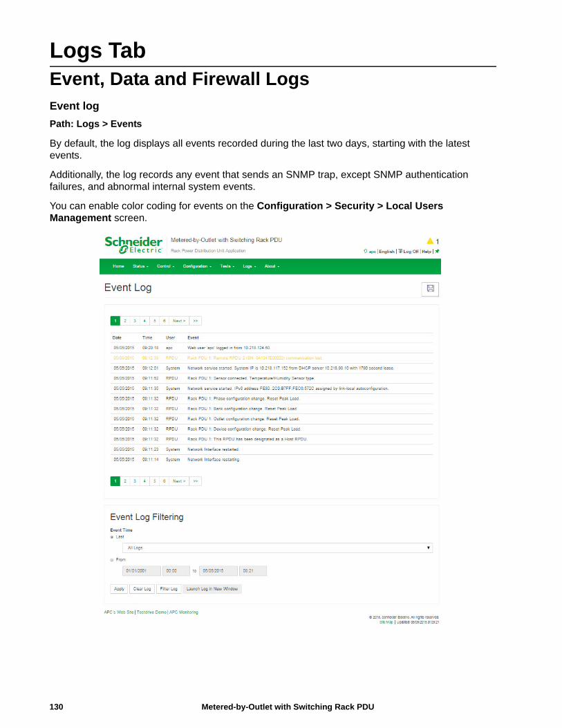
Logs TabEvent, Data and Firewall LogsEvent log
Path: Logs > Events
By default, the log displays all events recorded during the last two days, starting with the latest events.
Additionally, the log records any event that sends an SNMP trap, except SNMP authentication failures, and abnormal internal system events.
You can enable color coding for events on the Configuration > Security > Local Users Management screen.
Metered-by-Outlet with Switching Rack PDU130
Path: Logs > Events > Log
By default, the event log displays the most recent events first. To see the events listed together on a Web page, click Launch Log in New Window.
To open the log in a text file or to save the log to disk, click on the floppy disk icon( ) on the same line as the Event Log heading.
You can also use FTP or Secure CoPy (SCP) to view the event log. See “Use FTP or SCP to retrieve log files” on page 134.
Filtering event logs. Use filtering to omit information you don’t want to display.
• Filtering the log by date or time: Use the Last or From radio buttons. (The filter configuration is saved until the RPDU restarts.)
• Filtering the log by event severity or category:
– Click Filter Log.
– Clear a check box to remove it from view.
– After you click Apply, text at the upper right corner of the Event Log page indicates that a filter is active. The filter is active until you clear it or until the RPDU restarts.
• Removing an active filter:
– Click Filter Log.
– Click Clear Filter (Show All).
– As Administrator, click Save As Default to save this filter as the new default log view for all users.
Important points on filtering:
• Events are processed through the filter using OR logic. If you apply a filter, it works regardless of the other filters.
• Events that you cleared in the Filter By Severity list never display in the filtered Event Log, even if selected in the Filter by Category list.
• Similarly, events that you clear in the Filter by Category list never display in the filtered Event Log.
Deleting event logs. To delete all events, click Clear Log. Deleted events cannot be retrieved.
To disable the logging of events based on their assigned severity level or their event category, see “Configure event actions” on page 118
Path: Logs > Events > Reverse Lookup
With reverse lookup enabled, when a network-related event occurs, both the IP address and the domain name for the networked device with the event are logged in the event log. If no domain name entry exists for the device, only its IP address is logged with the event.
Since domain names generally change less frequently than IP addresses, enabling reverse lookup can improve the ability to identify addresses of networked devices that are causing events.
Reverse lookup is disabled by default. You should not need to enable it if you have no DNS server configured or have poor network performance because of heavy network traffic.
Path: Logs > Events > Size
Use Event Log Size to specify the maximum number of log entries.
Note: When you resize the event log in order to specify a maximum size, all existing log entries are deleted. When the log subsequently reaches the maximum size, the older entries are deleted.
131Metered-by-Outlet with Switching Rack PDU
Network Port Sharing event logs and traps.
Rack PDU events from guest PDUs are sent to the host PDU for inclusion into its log. The log entry will include the Display ID of the unit that the event occurred on.These events are then handled the same as local events from the host PDU. Therefore alarms, SNMP traps, e-mails, Syslog, etc will support Rack PDU events and alarms from all Rack PDUs in a group.
Example event log: Rack PDU 4: Device low load.
Note: System events will only be logged for the host PDU. System events from guest PDUs will not be logged on the host PDU.
Data log
Use the data log to display measurements about the Rack PDU, the power input to the Rack PDU, and the ambient temperature of the Rack PDU.
The steps to display and resize the data log are the same as for the event log, except that you use menu options under Data instead of Events.
Path: Logs > Data > Log
Filtering data logs. Use filtering to omit information you don’t want to display. Using the Network Port Sharing Data Log, the host Rack PDU will poll data from guest Rack PDUs so that data from all Rack PDUs in a group are available. To view data from a different Rack PDU in a group, select the desired Rack PDU from the "Filter Log" pull-down list.
Similarly for data log graphing, you can select a different Rack PDU by clicking on the Change Data Filter button.
• Filtering the log by date or time: Use the Last or From radio buttons. (The filter configuration is saved until the Rack PDU restarts.)
• Filtering the log by event severity or category:
a. Click Filter Log.
b. Clear a check box to remove it from view.
c. After you click Apply, text at the upper right corner of the Data Log page indicates that a filter is active. The filter is active until you clear it or until the Rack PDU restarts.
• Removing an active filter:
d. Click Filter Log.
e. Click Clear Filter (Show All).
f. As Administrator, click Save As Default to save this filter as the new default log view for all users.
Deleting data logs. To delete all data log records, click Clear Data Log. Deleted data log records cannot be retrieved.
Path: Logs > Data > Interval
Define, in the Log Interval setting, how frequently data is searched for and stored in the data log. When you click Apply, the number of possible storage days is recalculated and display at the top of the screen. When the log is full, the oldest entries are deleted.
Note: Because the interval specifies how often the data is recorded, the smaller the interval, the more times the data is recorded and the larger the log file.
Metered-by-Outlet with Switching Rack PDU132

Path: Logs > Data > Graphing
Data log graphing provides a graphical display of logged data and is an enhancement of the existing data log feature. How the graphing enhancement displays data and how efficiently it performs will vary depending on your computer hardware, computer operating system, and the Web browser you use to access the interface of the unit.
Note: JavaScript® must be enabled in your browser to use the graphing feature. Alternatively, you can use FTP or SCP to import the data log into a spreadsheet application, and graph data in the spreadsheet
Graph Data . Select the data items that correspond to the abbreviated column headings in the data log to graph multiple data items. Hold down CTRL to select multiple items.
Graph Time. Select Last to graph all records or to change the number of hours, days, or weeks for which data log information is graphed. Select a time option from the drop-down menu. Select From to graph data logged during a specific time period.Note: Enter time using the 24-hour clock format.
Apply. Click Apply to graph the data.
Launch Graph in New Window. Click Launch Graph in New Window to launch the data log graph in a new browser window that provides a larger view of the graph.
Path: Logs > Data > Rotation
Rotation causes the contents of the data log to be appended to the file you specify by name and location. Use this option to set up password-protection and other parameters.
• FTP Server: The IP address or host name of the server where the file will reside.
• User Name/Password: The user name with password required to send data to the repository file. This user must also be configured to have read and write access to the data repository file and the directory (folder) in which it is stored.
• File Path: The path to the repository file.
• Filename: The name of the repository file (an ASCII text file), e.g. datalog.txt. Any new data is appended to this file: it does not overwrite it.
• Unique Filename: Select this check box to save the log as mmddyyyy_<filename>.txt, where filename is what you specified in the Filename field above. Any new data is appended to the file but each day has its own file.
• Delay n hours between uploads: The number of hours between uploads of data to the file (max. 24 hours).
• Upon failure, try uploading every n minutes: The number of minutes between attempts to upload data to the file after a failed upload.
– Up to n times: The maximum number of times the upload will be attempted after it fails initially.
– Until upload succeeds: Attempt to upload the file until the transfer is completed.
Path: Logs > Data > Size
Use Data Log Size to specify the maximum number of log entries.
Note: When you resize the data log in order to specify a maximum size, all existing log entries are deleted. When the log subsequently reaches the maximum size, the older entries are deleted.
133Metered-by-Outlet with Switching Rack PDU
Firewall Logs
Path: Logs > Firewall
If you create a firewall policy, firewall events will be logged here.
The information in the log can be useful to help the technical support team solve problems. Log entries contain information about the traffic and the rules action (allowed, discarded). When logged here, these events are not logged in the main Event Log (see “Event log” on page 130).
A firewall log contains up to 50 of the most recent events. The firewall log is cleared when the management interface reboots.
Use FTP or SCP to retrieve log files
An Administrator or Device User can use FTP or SCP to retrieve a tab-delineated event log file (event.txt) or data log file (data.txt) and import it into a spreadsheet.
• The file reports all events or data recorded since the log was last deleted or (for the data log) truncated because it reached maximum size.
• The file includes information that the event log or data log does not display.
– The version of the file format (first field)
– The date and time the file was retrieved
– The Name, Contact, and Location values and IP address of the Rack PDU
– The unique Event Code for each recorded event (event.txt file only)
Note: The Rack PDU uses a four-digit year for log entries. You may need to select a four-digit date format in your spreadsheet application to display all four digits.
If you are using the encryption-based security protocols for your system, use SCP to retrieve the log file.
If you are using unencrypted authentication methods for the security of your system, use FTP to retrieve the log file.
See the Security Handbook, available at www.schneider-electric.com, for information on available protocols and methods for setting up the type of security you need.
To use SCP to retrieve the files To retrieve the event.txt file, use the following command:
scp username@hostname_or_ip_address:event.txt ./event.txt
To use SCP to retrieve the data.txt file, use the following command:
scp username@hostname_or_ip_address:data.txt ./data.txt
Metered-by-Outlet with Switching Rack PDU134
To use FTP to retrieve the event.txt or data.txt files
1. At a command prompt, type ftp and the IP address of the Rack PDU, and press ENTER.
If the Port setting for the FTP Server option (set through the Network menu of the Administration tab) has been changed from its default (21), you must use the non-default value in the FTP command. For Windows FTP clients, use the following command, including spaces. (For some FTP clients, you must use a colon instead of a space between the IP address and the port number.)ftp>open ip_address port_number
To set a non-default port value to enhance security for the FTP Server, see “FTP Server” on page 117. You can specify any port from 5001 to 32768.
2. Use the case-sensitive User Name and Password for Administrator or Device User to log on. For Administrator, apc is the default for User Name and Password. For the Device User, the defaults are device for User Name and apc for Password.
3. Use the get command to transmit the text of a log to your local drive.
ftp>get event.txt
or
ftp>get data.txt
4. Type quit at the ftp> prompt to exit from FTP.
135Metered-by-Outlet with Switching Rack PDU
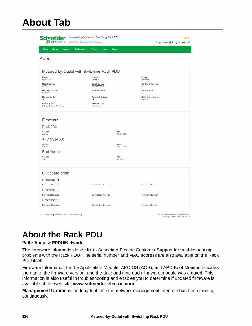
About Tab
About the Rack PDU Path: About > RPDU/Network
The hardware information is useful to Schneider Electric Customer Support for troubleshooting problems with the Rack PDU. The serial number and MAC address are also available on the Rack PDU itself.
Firmware information for the Application Module, APC OS (AOS), and APC Boot Monitor indicates the name, the firmware version, and the date and time each firmware module was created. This information is also useful in troubleshooting and enables you to determine if updated firmware is available at the web site, www.schneider-electric.com.
Management Uptime is the length of time the network management interface has been running continuously.
Metered-by-Outlet with Switching Rack PDU136
137Metered-by-Outlet with Switching Rack PDU
Device IP Configuration Wizard
Capabilities, Requirements, and InstallationHow to use the Wizard to configure TCP/IP settingsThe Device IP Configuration Wizard can discover Rack PDUs that do not have an IP address assigned. Once discovered, you can configure the IP address settings for the cards.
You can also search for devices already on the network by entering an IP range to define the search. The Utility scans the IP addresses in the defined range and discovers Rack PDUs that already have a DHCP-assigned IP address.
Note: For detailed information on the Utility, see the Knowledge Base on the support page of the www.schneider-electric.com website and search for FA156064 (the ID of the relevant article).
Note: To use the DHCP Option 12 (AOS 5.1.5 or higher), see Knowledge Base ID FA156110.
System requirements
The Device IP Configuration Wizard runs on Microsoft® Windows® 2000, Windows Server® 2003, Windows Server® 2012, and on 32- and 64-bit versions of Windows XP, Windows Vista, Windows 2008, Windows 7, and Windows 8 operating systems.
The Device IP Configuration Wizard supports cards that have firmware version 3.0.x or higher and is for IPv4 only.
Installation
To install the Device IP Configuration Wizard from a downloaded executable file
1. Go to www.schneider-electric.com
2. Download the Device IP Configuration Wizard.
3. Run the downloaded executable file.
When installed, the Device IP Configuration Wizard is available through the Windows Start menu options.
How to Export Configuration Settings
Retrieving and Exporting the .ini FileSummary of the procedure
A Super User/Administrator can retrieve the .ini file of a RPDU and export it to another RPDU or to multiple Rack PDUs. The steps are below; see details in the sections following.
1. Configure a RPDU with the desired settings and export them.
2. Retrieve the .ini file from that RPDU.
3. Customize the file to change the TCP/IP settings at least.
4. Use a file transfer protocol supported by the RPDU to transfer a copy to one or more other Rack PDUs. For a transfer to multiple Rack PDUs, use an FTP or SCP script or the .ini file utility.
Each receiving RPDU uses the file to reconfigure its own settings and then deletes it.
Note: Managing Users via the config.ini - Users are no longer managed via the config.ini in any form. Users are now managed via a separate file with the .csf extension. For further information on this topic, refer to article ID FA176542 in the Knowledge Base at www.schneider-electric.com.
Contents of the .ini file
The config.ini file you retrieve from a RPDU contains the following:
• Section headings and keywords (only those supported for the particular device from which you retrieve the file): Section headings are category names enclosed in brackets ([ ]). Keywords, under each section heading, are labels describing specific RPDU settings. Each keyword is followed by an equals sign and a value (either the default or a configured value).
• The Override keyword: With its default value, this keyword prevents the exporting of one or more keywords and their device-specific values. For example, in the [NetworkTCP/IP] section, the default value for Override (the MAC address of the RPDU) blocks the exporting of values for the SystemIP, SubnetMask, DefaultGateway, and BootMode.
.ini and Network Port Sharing
The .ini configuration utility is able to get and set values for all Rack PDUs in a group. In order to be backwards compatible, the host Rack PDU will always be designated as first, "PDU_A". Any guest Rack PDUs are then designated "PDU_B", "PDU_C", and "PDU_D" based on their Display ID in ascending order. Therefore, "PDU_A" will not necessarily correlate to Display ID 1, and so on.
Note: Because of the large number of configuration values possible in a Rack PDU group, it may take a very long time to process an INI file set. For example, a Rack PDU group of 4 units with all values changing may take 30 minutes to complete processing.
Metered-by-Outlet with Switching Rack PDU138
Detailed procedures
Retrieving. To set up and retrieve an .ini file to export:
1. If possible, use the interface of a RPDU to configure it with the settings to export. (Directly editing the .ini file risks introducing errors).
2. To use FTP to retrieve config.ini from the configured RPDU:
a. Open a connection to the RPDU using its IP address:
ftp> open ip_address
b. Log on using the Super User/Administrator user name and password.
c. Retrieve the config.ini file containing the settings of the RPDU:
ftp> get config.ini
The file is written to the folder from which you launched the FTP.
To retrieve configuration settings from multiple Rack PDUs and export them to other Rack PDUs, see Release Notes: ini File Utility, version 2.0, available at www.schneider-electric.com.
Customizing You must customize the file before you export it.
1. Use a text editor to customize the file.
– Section headings, keywords, and pre-defined values are not case-sensitive, but string values that you define are case-sensitive.
– Use adjacent quotation marks to indicate no value. For example, LinkURL1="" indicates that the URL is intentionally undefined.
– Enclose in quotation marks any values that contain leading or trailing spaces or are already enclosed in quotation marks.
– To export scheduled events, configure the values directly in the .ini file.
– To export a system time with the greatest accuracy, if the receiving Rack PDUs can access a Network Time Protocol server, configure enabled for NTPEnable:
NTPEnable=enabled
Alternatively, reduce transmission time by exporting the [SystemDate/Time] section as a separate .ini file.
– To add comments, start each comment line with a semicolon (;).
2. Copy the customized file to another file name in the same folder:
– The file name can have up to 64 characters and must have the .ini suffix.
– Retain the original customized file for future use. The file that you retain is the only record of your comments.
139Metered-by-Outlet with Switching Rack PDU
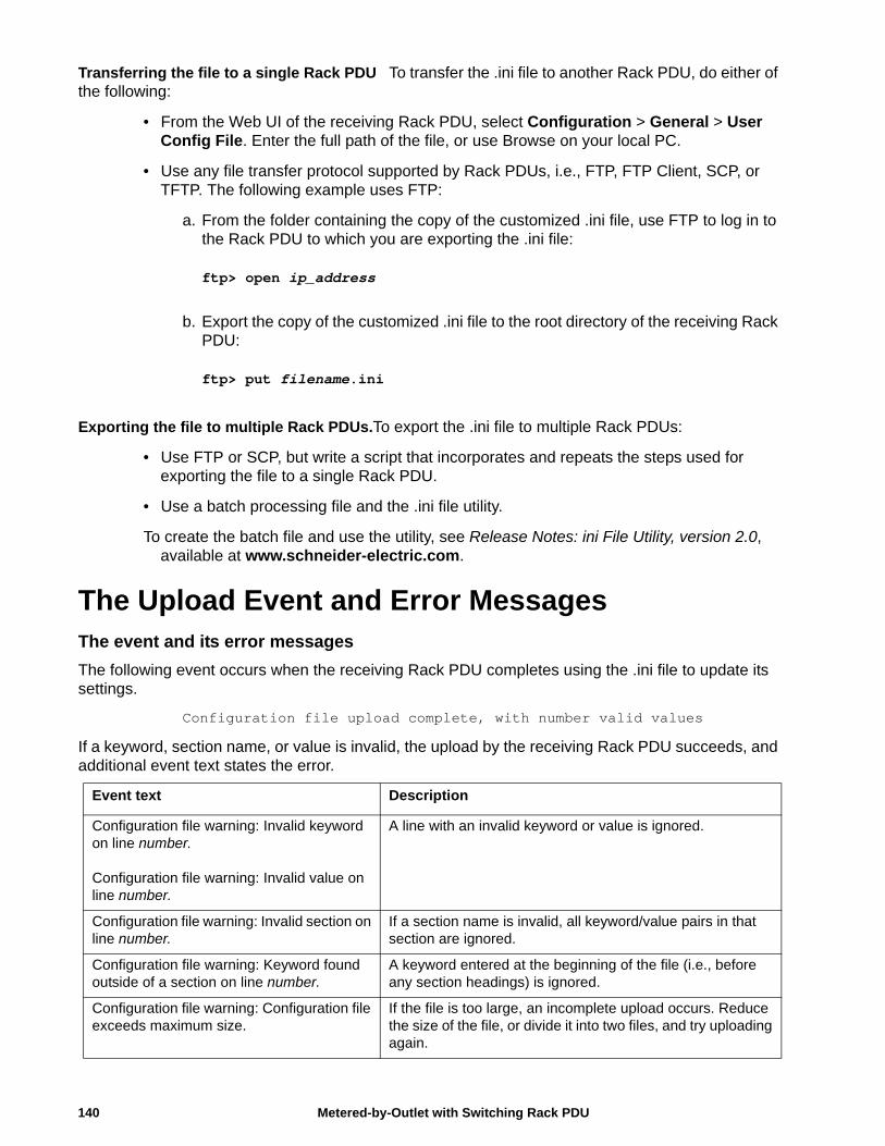
Transferring the file to a single Rack PDU To transfer the .ini file to another Rack PDU, do either of the following:
• From the Web UI of the receiving Rack PDU, select Configuration > General > User Config File. Enter the full path of the file, or use Browse on your local PC.
• Use any file transfer protocol supported by Rack PDUs, i.e., FTP, FTP Client, SCP, or TFTP. The following example uses FTP:
a. From the folder containing the copy of the customized .ini file, use FTP to log in to the Rack PDU to which you are exporting the .ini file:
ftp> open ip_address
b. Export the copy of the customized .ini file to the root directory of the receiving Rack PDU:
ftp> put filename.ini
Exporting the file to multiple Rack PDUs.To export the .ini file to multiple Rack PDUs:
• Use FTP or SCP, but write a script that incorporates and repeats the steps used for exporting the file to a single Rack PDU.
• Use a batch processing file and the .ini file utility.
To create the batch file and use the utility, see Release Notes: ini File Utility, version 2.0, available at www.schneider-electric.com.
The Upload Event and Error MessagesThe event and its error messages
The following event occurs when the receiving Rack PDU completes using the .ini file to update its settings.
Configuration file upload complete, with number valid values
If a keyword, section name, or value is invalid, the upload by the receiving Rack PDU succeeds, and additional event text states the error.
Event text Description
Configuration file warning: Invalid keyword on line number.
Configuration file warning: Invalid value on line number.
A line with an invalid keyword or value is ignored.
Configuration file warning: Invalid section on line number.
If a section name is invalid, all keyword/value pairs in that section are ignored.
Configuration file warning: Keyword found outside of a section on line number.
A keyword entered at the beginning of the file (i.e., before any section headings) is ignored.
Configuration file warning: Configuration file exceeds maximum size.
If the file is too large, an incomplete upload occurs. Reduce the size of the file, or divide it into two files, and try uploading again.
Metered-by-Outlet with Switching Rack PDU140
Messages in config.ini
A Rack PDU from which you download the config.ini file must be discovered successfully in order for its configuration to be included. If the Rack PDU is not present or is not discovered, the config.ini file contains a message under the appropriate section name, instead of keywords and values. For example:Rack PDU not discovered
If you did not intend to export the Rack PDU configuration as part of the .ini file import, ignore these messages.
Errors generated by overridden values
The Override keyword and its value will generate error messages in the event log when it blocks the exporting of values. See “Contents of the .ini file” on page 138 for information about which values are overridden.
Because the overridden values are device-specific and not appropriate to export to other Rack PDUs, ignore these error messages. To prevent these error messages, delete the lines that contain the Override keyword and the lines that contain the values that they override. Do not delete or change the line containing the section heading.
Related TopicsOn Windows operating systems, instead of transferring .ini files, you can use the Device IP Configuration Wizard to update the basic TCP/IP settings of the Rack PDU and configure other settings through its user interface. See “Device IP Configuration Wizard” on page 137.
141Metered-by-Outlet with Switching Rack PDU
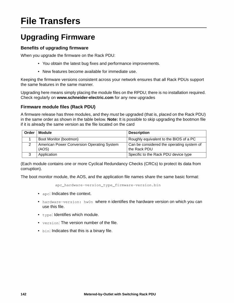
File Transfers
Upgrading FirmwareBenefits of upgrading firmware
When you upgrade the firmware on the Rack PDU:
• You obtain the latest bug fixes and performance improvements.
• New features become available for immediate use.
Keeping the firmware versions consistent across your network ensures that all Rack PDUs support the same features in the same manner.
Upgrading here means simply placing the module files on the RPDU; there is no installation required. Check regularly on www.schneider-electric.com for any new upgrades
Firmware module files (Rack PDU)
A firmware release has three modules, and they must be upgraded (that is, placed on the Rack PDU) in the same order as shown in the table below. Note: It is possible to skip upgrading the bootmon file if it is already the same version as the file located on the card
(Each module contains one or more Cyclical Redundancy Checks (CRCs) to protect its data from corruption).
The boot monitor module, the AOS, and the application file names share the same basic format:
apc_hardware-version_type_firmware-version.bin
• apc: Indicates the context.
• hardware-version: hw0n where n identifies the hardware version on which you can use this file.
• type: Identifies which module.
• version: The version number of the file.
• bin: Indicates that this is a binary file.
Order Module Description
1 Boot Monitor (bootmon) Roughly equivalent to the BIOS of a PC
2 American Power Conversion Operating System (AOS)
Can be considered the operating system of the Rack PDU
3 Application Specific to the Rack PDU device type
Metered-by-Outlet with Switching Rack PDU142
Firmware File Transfer MethodsNote: Upgrade the bootmon module first, then the AOS module, and finally, the application module by placing them on the RPDU in that order.
Obtain the free, latest firmware version from the Schneider Electric web site. To upgrade the firmware of one or more RPDUs, use 1 of these 5 methods:
• On a Windows operating system, use the Firmware Upgrade Utility downloaded from the web site www.schneider-electric.com.
• On any supported operating system, use FTP or SCP to transfer the individual AOS and application firmware modules.
• For a Rack PDU that is NOT on your network, use XMODEM through a serial connection to transfer the individual firmware modules from your computer to the Rack PDU.
• Use a USB drive to transfer the individual firmware modules from your computer. See “How to upgrade multiple RPDUs” on page 146.
• For upgrades to multiple RPDUs, see “Upgrading the firmware on multiple Rack PDUs” and “Using the Firmware Upgrade Utility for multiple upgrades on Windows”.
Using the Firmware Upgrade Utility
This Firmware Upgrade Utility is part of the firmware upgrade package available on the www.schneider-electric.com website. (Never use an Upgrade Utility designated for one product to upgrade the firmware of another product).
Using the Utility for upgrades on Windows-based systemsOn any supported Windows operating system, the Firmware Upgrade Utility automates the transferring of the firmware modules, in the correct module order.
Unzip the downloaded firmware upgrade file and double-click the .exe file. Then enter the IP address, the user name, and the password in the dialog fields and click Upgrade Now. You can use the Ping button to test your entered details. See “How to upgrade multiple RPDUs” on page 146.
Using the Utility for manual upgrades, primarily on Linux.On non-Windows operating systems, the Firmware Upgrade Utility extracts the individual firmware modules, but does not upgrade the Rack PDU. See “Firmware File Transfer Methods” on page 143 for the different upgrade methods after extraction.
To extract the firmware files:
1. After extracting files from the downloaded firmware upgrade file, run the Firmware Upgrade Utility (the .exe file).
2. At the prompts, click Next>, and then specify the directory location to which the files will be extracted.
3. When the Extraction Complete message displays, close the dialog box.
143Metered-by-Outlet with Switching Rack PDU
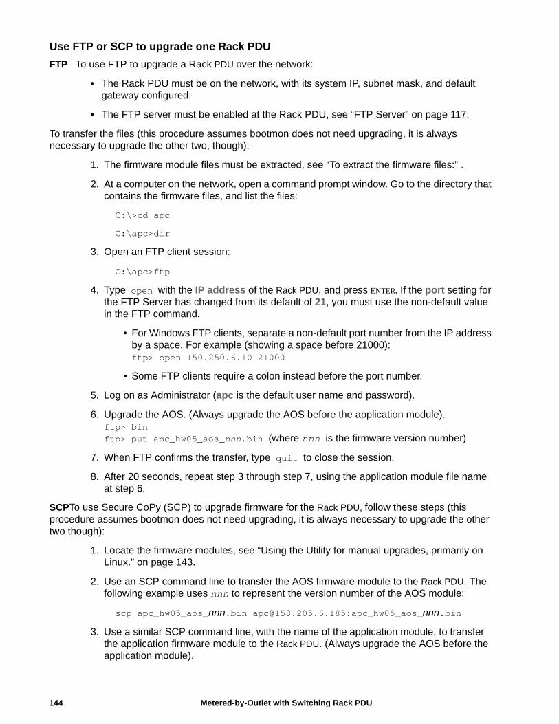
Use FTP or SCP to upgrade one Rack PDU
FTP To use FTP to upgrade a Rack PDU over the network:
• The Rack PDU must be on the network, with its system IP, subnet mask, and default gateway configured.
• The FTP server must be enabled at the Rack PDU, see “FTP Server” on page 117.
To transfer the files (this procedure assumes bootmon does not need upgrading, it is always necessary to upgrade the other two, though):
1. The firmware module files must be extracted, see “To extract the firmware files:” .
2. At a computer on the network, open a command prompt window. Go to the directory that contains the firmware files, and list the files:
C:\>cd apc
C:\apc>dir
3. Open an FTP client session:
C:\apc>ftp
4. Type open with the IP address of the Rack PDU, and press ENTER. If the port setting for the FTP Server has changed from its default of 21, you must use the non-default value in the FTP command.
• For Windows FTP clients, separate a non-default port number from the IP address by a space. For example (showing a space before 21000):ftp> open 150.250.6.10 21000
• Some FTP clients require a colon instead before the port number.
5. Log on as Administrator (apc is the default user name and password).
6. Upgrade the AOS. (Always upgrade the AOS before the application module).ftp> binftp> put apc_hw05_aos_nnn.bin (where nnn is the firmware version number)
7. When FTP confirms the transfer, type quit to close the session.
8. After 20 seconds, repeat step 3 through step 7, using the application module file name at step 6,
SCPTo use Secure CoPy (SCP) to upgrade firmware for the Rack PDU, follow these steps (this procedure assumes bootmon does not need upgrading, it is always necessary to upgrade the other two though):
1. Locate the firmware modules, see “Using the Utility for manual upgrades, primarily on Linux.” on page 143.
2. Use an SCP command line to transfer the AOS firmware module to the Rack PDU. The following example uses nnn to represent the version number of the AOS module:
scp apc_hw05_aos_nnn.bin [email protected]:apc_hw05_aos_nnn.bin
3. Use a similar SCP command line, with the name of the application module, to transfer the application firmware module to the Rack PDU. (Always upgrade the AOS before the application module).
Metered-by-Outlet with Switching Rack PDU144
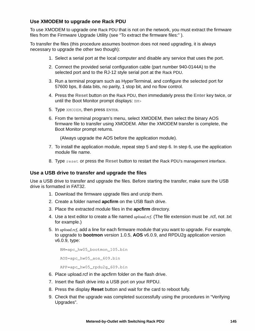
Use XMODEM to upgrade one Rack PDU
To use XMODEM to upgrade one Rack PDU that is not on the network, you must extract the firmware files from the Firmware Upgrade Utility (see “To extract the firmware files:” ).
To transfer the files (this procedure assumes bootmon does not need upgrading, it is always necessary to upgrade the other two though):
1. Select a serial port at the local computer and disable any service that uses the port.
2. Connect the provided serial configuration cable (part number 940-0144A) to the selected port and to the RJ-12 style serial port at the Rack PDU.
3. Run a terminal program such as HyperTerminal, and configure the selected port for 57600 bps, 8 data bits, no parity, 1 stop bit, and no flow control.
4. Press the Reset button on the Rack PDU, then immediately press the Enter key twice, or until the Boot Monitor prompt displays: BM>
5. Type XMODEM, then press ENTER.
6. From the terminal program’s menu, select XMODEM, then select the binary AOS firmware file to transfer using XMODEM. After the XMODEM transfer is complete, the Boot Monitor prompt returns.
(Always upgrade the AOS before the application module).
7. To install the application module, repeat step 5 and step 6. In step 6, use the application module file name.
8. Type reset or press the Reset button to restart the Rack PDU’s management interface.
Use a USB drive to transfer and upgrade the files
Use a USB drive to transfer and upgrade the files. Before starting the transfer, make sure the USB drive is formatted in FAT32.
1. Download the firmware upgrade files and unzip them.
2. Create a folder named apcfirm on the USB flash drive.
3. Place the extracted module files in the apcfirm directory.
4. Use a text editor to create a file named upload.rcf. (The file extension must be .rcf, not .txt for example.)
5. In upload.rcf, add a line for each firmware module that you want to upgrade. For example, to upgrade to bootmon version 1.0.5, AOS v6.0.9, and RPDU2g application version v6.0.9, type:
BM=apc_hw05_bootmon_105.bin
AOS=apc_hw05_aos_609.bin
APP=apc_hw05_rpdu2g_609.bin
6. Place upload.rcf in the apcfirm folder on the flash drive.
7. Insert the flash drive into a USB port on your RPDU.
8. Press the display Reset button and wait for the card to reboot fully.
9. Check that the upgrade was completed successfully using the procedures in “Verifying Upgrades”.
145Metered-by-Outlet with Switching Rack PDU
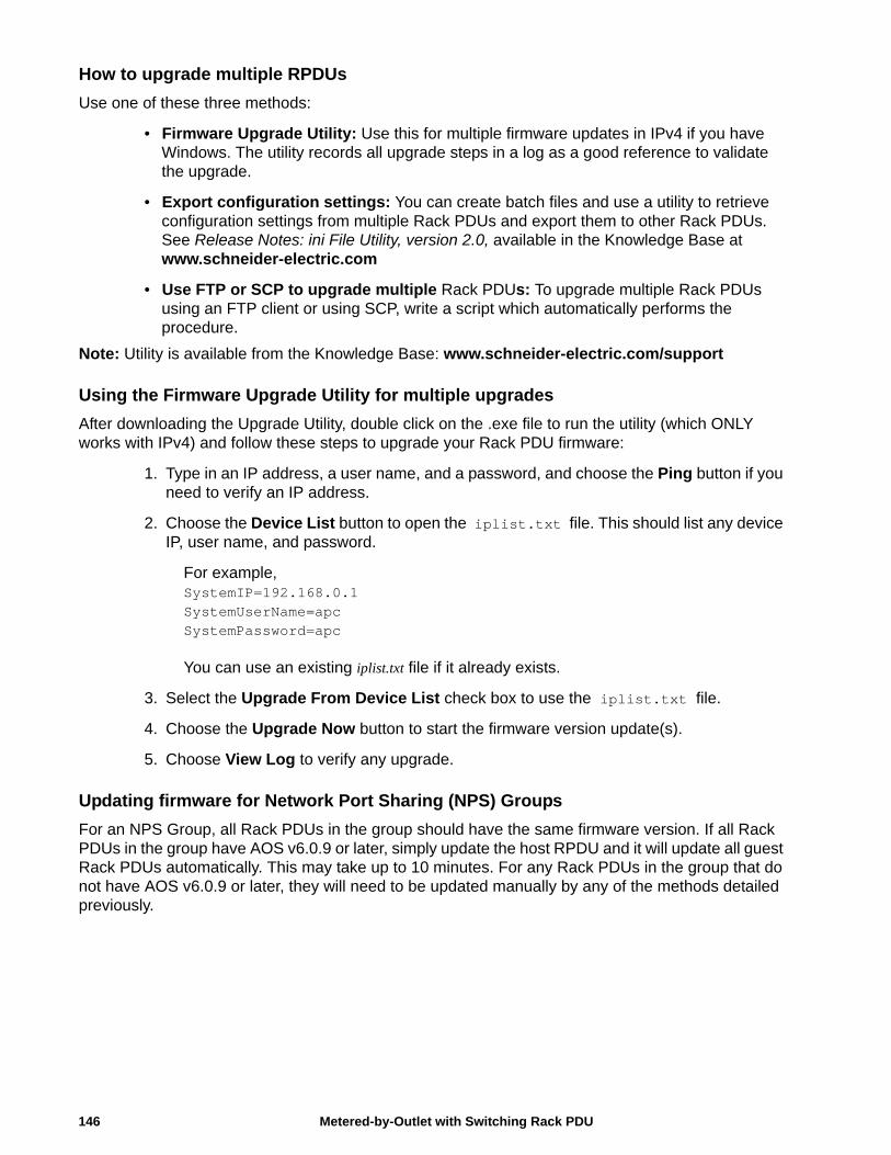
How to upgrade multiple RPDUs
Use one of these three methods:
• Firmware Upgrade Utility: Use this for multiple firmware updates in IPv4 if you have Windows. The utility records all upgrade steps in a log as a good reference to validate the upgrade.
• Export configuration settings: You can create batch files and use a utility to retrieve configuration settings from multiple Rack PDUs and export them to other Rack PDUs. See Release Notes: ini File Utility, version 2.0, available in the Knowledge Base at www.schneider-electric.com
• Use FTP or SCP to upgrade multiple Rack PDUs: To upgrade multiple Rack PDUs using an FTP client or using SCP, write a script which automatically performs the procedure.
Note: Utility is available from the Knowledge Base: www.schneider-electric.com/support
Using the Firmware Upgrade Utility for multiple upgrades
After downloading the Upgrade Utility, double click on the .exe file to run the utility (which ONLY works with IPv4) and follow these steps to upgrade your Rack PDU firmware:
1. Type in an IP address, a user name, and a password, and choose the Ping button if you need to verify an IP address.
2. Choose the Device List button to open the iplist.txt file. This should list any device IP, user name, and password.
For example, SystemIP=192.168.0.1SystemUserName=apcSystemPassword=apc
You can use an existing iplist.txt file if it already exists.
3. Select the Upgrade From Device List check box to use the iplist.txt file.
4. Choose the Upgrade Now button to start the firmware version update(s).
5. Choose View Log to verify any upgrade.
Updating firmware for Network Port Sharing (NPS) Groups
For an NPS Group, all Rack PDUs in the group should have the same firmware version. If all Rack PDUs in the group have AOS v6.0.9 or later, simply update the host RPDU and it will update all guest Rack PDUs automatically. This may take up to 10 minutes. For any Rack PDUs in the group that do not have AOS v6.0.9 or later, they will need to be updated manually by any of the methods detailed previously.
Metered-by-Outlet with Switching Rack PDU146
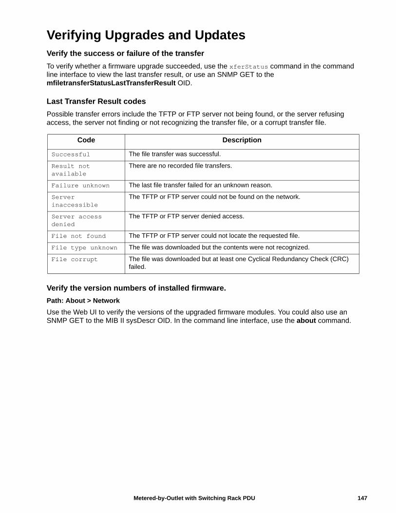
Verifying Upgrades and UpdatesVerify the success or failure of the transfer
To verify whether a firmware upgrade succeeded, use the xferStatus command in the command line interface to view the last transfer result, or use an SNMP GET to the mfiletransferStatusLastTransferResult OID.
Last Transfer Result codes
Possible transfer errors include the TFTP or FTP server not being found, or the server refusing access, the server not finding or not recognizing the transfer file, or a corrupt transfer file.
Verify the version numbers of installed firmware.
Path: About > Network
Use the Web UI to verify the versions of the upgraded firmware modules. You could also use an SNMP GET to the MIB II sysDescr OID. In the command line interface, use the about command.
Code Description
Successful The file transfer was successful.
Result not available
There are no recorded file transfers.
Failure unknown The last file transfer failed for an unknown reason.
Server inaccessible
The TFTP or FTP server could not be found on the network.
Server access denied
The TFTP or FTP server denied access.
File not found The TFTP or FTP server could not locate the requested file.
File type unknown The file was downloaded but the contents were not recognized.
File corrupt The file was downloaded but at least one Cyclical Redundancy Check (CRC) failed.
147Metered-by-Outlet with Switching Rack PDU
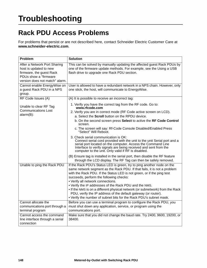
Troubleshooting
Rack PDU Access ProblemsFor problems that persist or are not described here, contact Schneider Electric Customer Care at www.schneider-electric.com.
Problem Solution
After a Network Port Sharing host is updated to new firmware, the guest Rack PDUs show a "firmware version does not match" alarm.
This can be solved by manually updating the affected guest Rack PDUs by one of the firmware update methods. For example, see the Using a USB flash drive to upgrade one Rack PDU section.
Cannot enable EnergyWise on a guest Rack PDU in a NPS group.
User is allowed to have a redundant network in a NPS chain. However, only one stick, the host, will communicate to EnergyWise.
RF Code Issues (A)
Unable to clear RF Tag Communications Lost alarm(B):
(A) It is possible to receive an incorrect tag:
1. Verify you have the correct tag from the RF code. Go to: www.rfcode.com
2. Verify you are in correct mode (RF Code active screen on LCD).a. Select the Scroll button on the RPDU device.b. On the second screen press Select to active the RF Code Control
screen.c. The screen will say: Rf-Code Console Disabled/Enabled Press
“Select” Will Reboot.
3. Check serial communication is OK: Connect serial cord provided with the unit to the unit Serial port and a serial port located on the computer. Access the Command Line Interface to verify signals are being received and sent from the computer to the unit. Only valid if RF is disabled.
(B) Ensure tag is installed in the serial port, then disable the RF feature through the LCD display. The RF Tag can then be safely removed.
Unable to ping the Rack PDU If the Rack PDU’s Status LED is green, try to ping another node on the same network segment as the Rack PDU. If that fails, it is not a problem with the Rack PDU. If the Status LED is not green, or if the ping test succeeds, perform the following checks:• Verify all network connections.• Verify the IP addresses of the Rack PDU and the NMS.• If the NMS is on a different physical network (or subnetwork) from the Rack
PDU, verify the IP address of the default gateway (or router).• Verify the number of subnet bits for the Rack PDU’s subnet mask.
Cannot allocate the communications port through a terminal program
Before you can use a terminal program to configure the Rack PDU, you must shut down any application, service, or program using the communications port.
Cannot access the command line interface through a serial connection
Make sure that you did not change the baud rate. Try 2400, 9600, 19200, or 38400.
Metered-by-Outlet with Switching Rack PDU148
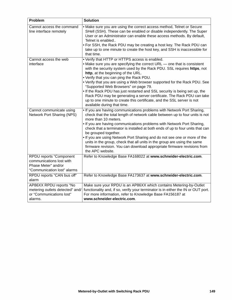
Cannot access the command line interface remotely
• Make sure you are using the correct access method, Telnet or Secure SHell (SSH). These can be enabled or disable independently. The Super User or an Administrator can enable these access methods. By default, Telnet is enabled..
• For SSH, the Rack PDU may be creating a host key. The Rack PDU can take up to one minute to create the host key, and SSH is inaccessible for that time.
Cannot access the web interface
• Verify that HTTP or HTTPS access is enabled.• Make sure you are specifying the correct URL — one that is consistent
with the security system used by the Rack PDU. SSL requires https, not http, at the beginning of the URL.
• Verify that you can ping the Rack PDU.• Verify that you are using a Web browser supported for the Rack PDU. See
“Supported Web Browsers” on page 79.• If the Rack PDU has just restarted and SSL security is being set up, the
Rack PDU may be generating a server certificate. The Rack PDU can take up to one minute to create this certificate, and the SSL server is not available during that time.
Cannot communicate using Network Port Sharing (NPS)
• If you are having communications problems with Network Port Sharing, check that the total length of network cable between up to four units is not more than 10 meters.
• If you are having communications problems with Network Port Sharing, check that a terminator is installed at both ends of up to four units that can be grouped together.
• If you are using Network Port Sharing and do not see one or more of the units in the group, check that all units in the group are using the same firmware revision. You can download appropriate firmware revisions from the APC website.
RPDU reports “Component communications lost with Phase Meter” and/or “Communication lost” alarms
Refer to Knowledge Base FA168022 at www.schneider-electric.com.
RPDU reports “CAN bus off” alarm
Refer to Knowledge Base FA173637 at www.schneider-electric.com.
AP86XX RPDU reports “No metering outlets detected” and/or “Communications lost” alarms.
Make sure your RPDU is an AP86XX which contains Metering-by-Outlet functionality and, if so, verify your terminator is in either the IN or OUT port. For more information, refer to Knowledge Base FA156187 at www.schneider-electric.com.
Problem Solution
149Metered-by-Outlet with Switching Rack PDU
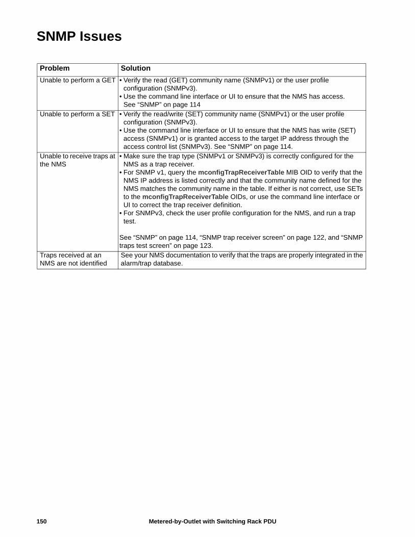
SNMP Issues
Problem Solution
Unable to perform a GET • Verify the read (GET) community name (SNMPv1) or the user profile configuration (SNMPv3).
• Use the command line interface or UI to ensure that the NMS has access.See “SNMP” on page 114
Unable to perform a SET • Verify the read/write (SET) community name (SNMPv1) or the user profile configuration (SNMPv3).
• Use the command line interface or UI to ensure that the NMS has write (SET) access (SNMPv1) or is granted access to the target IP address through the access control list (SNMPv3). See “SNMP” on page 114.
Unable to receive traps at the NMS
• Make sure the trap type (SNMPv1 or SNMPv3) is correctly configured for the NMS as a trap receiver.
• For SNMP v1, query the mconfigTrapReceiverTable MIB OID to verify that the NMS IP address is listed correctly and that the community name defined for the NMS matches the community name in the table. If either is not correct, use SETs to the mconfigTrapReceiverTable OIDs, or use the command line interface or UI to correct the trap receiver definition.
• For SNMPv3, check the user profile configuration for the NMS, and run a trap test.
See “SNMP” on page 114, “SNMP trap receiver screen” on page 122, and “SNMP traps test screen” on page 123.
Traps received at an NMS are not identified
See your NMS documentation to verify that the traps are properly integrated in the alarm/trap database.
Metered-by-Outlet with Switching Rack PDU150


Worldwide Customer Support
Customer support is available at www.schneider-electric.com.
4/2015990-5570A-001
© 2015 Schneider Electric. APC, PowerNet, and StruxureWare are trademarks owned by Schneider Electric, S.A.S. All other trademarks are property of their respective owners.


