42
Contents A career in aeroelasticity Louw van Zyl Presented to the Aeronautical Society of South Africa, 16 May 2019
ContentsA career in aeroelasticity
Louw van ZylPresented to the Aeronautical Society of South
Africa, 16 May 2019
2
Overview
• What is flutter?• History of flutter• Theory of flutter (light version)• Interesting projects• Interesting tools • Interesting people• Flutter considerations for pilots and technicians
3
What is flutter?
• Flutter is an unstable structural vibration resulting from the interaction between inertial, elastic and aerodynamic forces on an aircraft. Energy is extracted from the air stream resulting in increased amplitudes of vibration. It can destroy an aircraft in a fraction of a second.
• YF 117 crash. The accident investigation report concluded that the cause of the accident was structural failure of a support assembly, known as the Brooklyn Bridge, in the left wing due to four missing fasteners of the 39 in the assembly.
• Hawker 800 XP limit cycle oscillation. "Investigation of these incidents revealed missing aileron bushings, low cable tensions, and improperly installed brackets. After the operators corrected the airplanes to the type design configuration, as defined per the existing maintenance manuals, the oscillations did not recur."
4
History of flutter
• This information was taken from a 1981 paper by Garrick and Reed. • The first flutter problem is generally regarded as having been on the Handley
Page 400 bomber. Anti-symmetric elevator rotation coupled with the fuselage torsion mode to produce flutter. The cure was to interconnect the elevators, which were initially separately controlled by cables from the cockpit. The same problem and solution applied to the DH9 of the same era.
• The Germans experienced torsional divergence problems in the first world war. This affected amongst others the Fokker D-VIII aircraft as a result of a strengthening of the rear spar which moved the elastic axis rearwards.
• The concept of mass balancing of ailerons was introduced in the 1920s by the Dutch
• The study of unsteady aerodynamics was initiated by professor Prandtl in 1918• Between the two world wars racing aircraft encountered flutter, some of the
instances being wing bending-torsion flutter. Increasing torsional stiffness was often the solution.
5
History of flutter
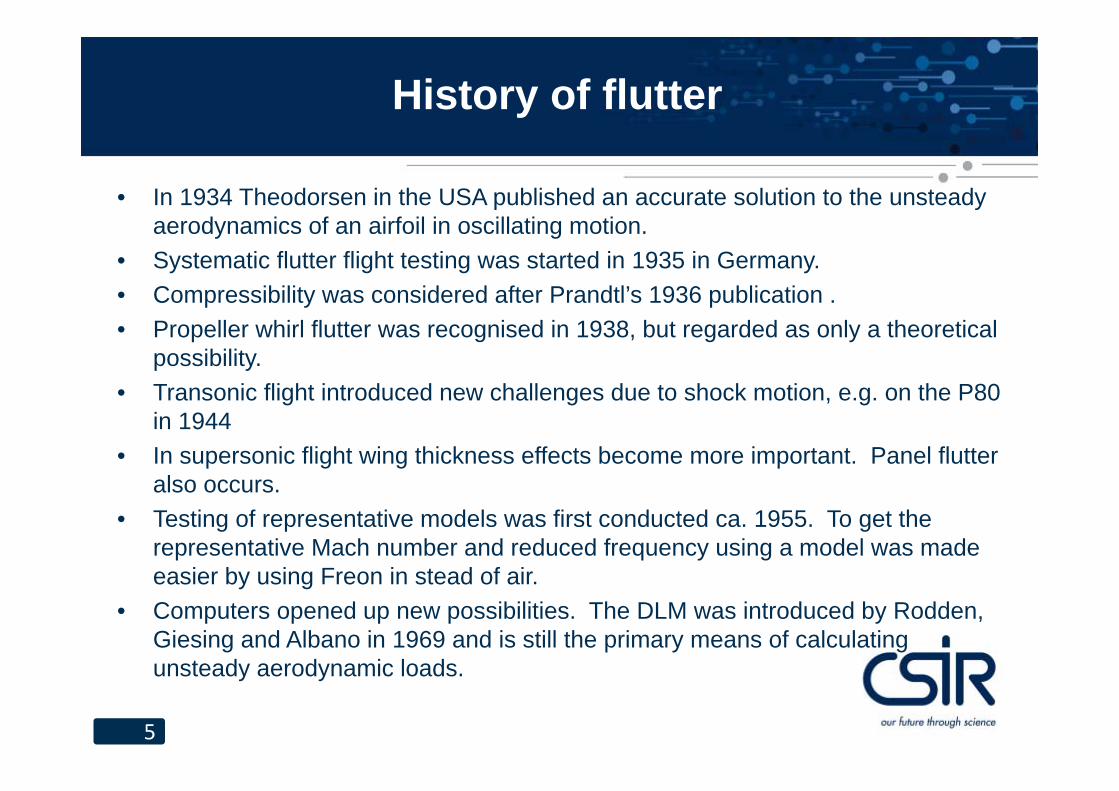
• In 1934 Theodorsen in the USA published an accurate solution to the unsteady aerodynamics of an airfoil in oscillating motion.
• Systematic flutter flight testing was started in 1935 in Germany.• Compressibility was considered after Prandtl’s 1936 publication .• Propeller whirl flutter was recognised in 1938, but regarded as only a theoretical
possibility.• Transonic flight introduced new challenges due to shock motion, e.g. on the P80
in 1944• In supersonic flight wing thickness effects become more important. Panel flutter
also occurs.• Testing of representative models was first conducted ca. 1955. To get the
representative Mach number and reduced frequency using a model was made easier by using Freon in stead of air.
• Computers opened up new possibilities. The DLM was introduced by Rodden, Giesing and Albano in 1969 and is still the primary means of calculating unsteady aerodynamic loads.
6
Theory of flutter
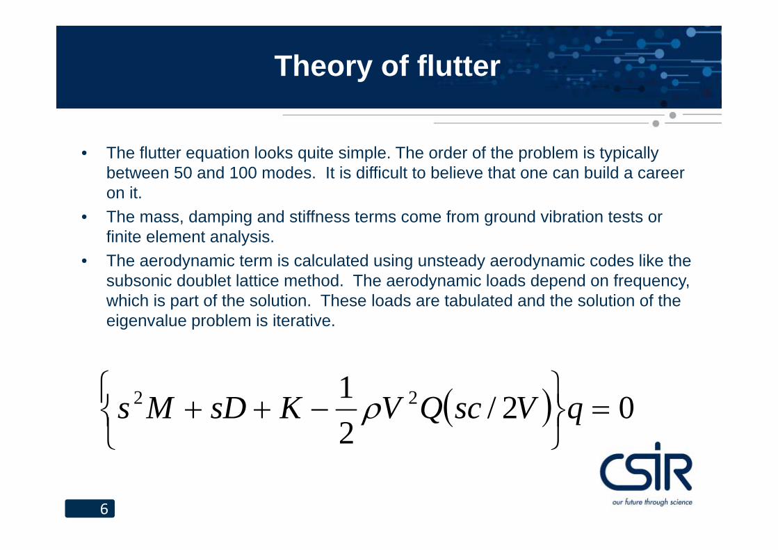
• The flutter equation looks quite simple. The order of the problem is typically between 50 and 100 modes. It is difficult to believe that one can build a career on it.
• The mass, damping and stiffness terms come from ground vibration tests or finite element analysis.
• The aerodynamic term is calculated using unsteady aerodynamic codes like the subsonic doublet lattice method. The aerodynamic loads depend on frequency, which is part of the solution. These loads are tabulated and the solution of the eigenvalue problem is iterative.
02/21 22
qVscQVKsDMs
7
Quirks of the equation
• Because of the iterative nature of the solution, one starts at a low speed assuming s to be equal to one of the natural mode frequencies. Solving the equation will give a slightly different value for s. (Actually, as many ses as there are modes. One has to choose one of them, which is a topic on its own.) Aerodynamics are determined for the new s and the solution is repeated. Usually the process converges.
• Because the equation depends on the solution, there is no fixed number of solutions under given conditions.
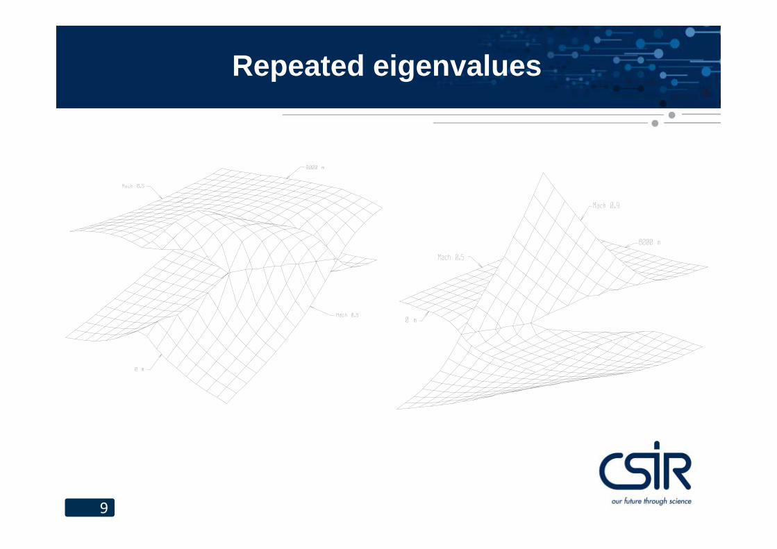
• If one “followed” a mode in this way around a portion of the flight envelope (altitude, speed) one would expect to arrive back at the beginning, but this is not the case if there are repeated eigenvalues within the portion of the flight envelope.
8
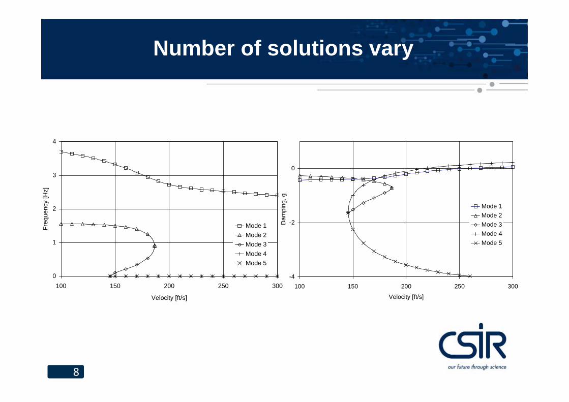
Number of solutions vary
0
1
2
3
4
100 150 200 250 300
Velocity [ft/s]
Freq
uenc
y [H
z]
Mode 1Mode 2Mode 3Mode 4Mode 5
-4
-2
0
100 150 200 250 300
Velocity [ft/s]
Dam
ping
, g
Mode 1Mode 2Mode 3Mode 4Mode 5
9
Repeated eigenvalues
10
Interesting projects
• In the 1980s the CSIR performed many flutter analyses for the South African Air Force, many on the Mirage F1.
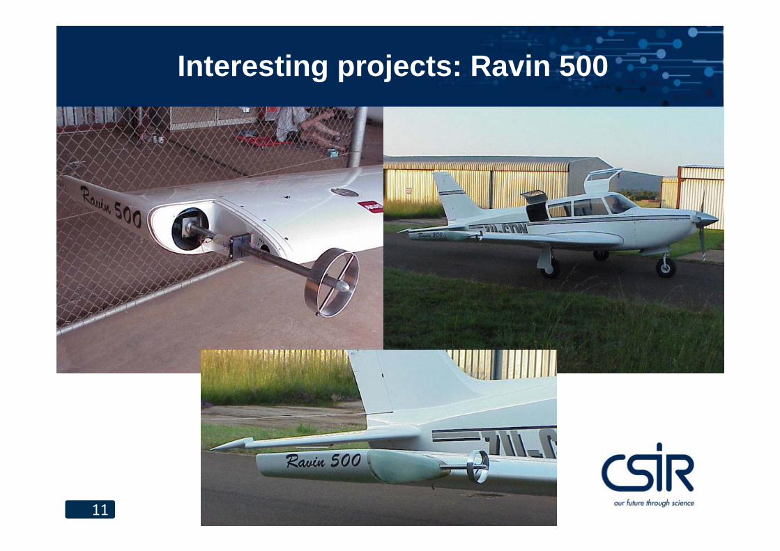
• Raven 500. CSIR performed ground vibration tests, flutter analysis and flutter flight testing on this aircraft. This was the start of the annular wing flutter exciter.
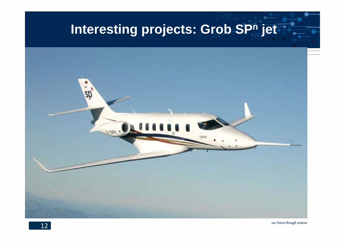
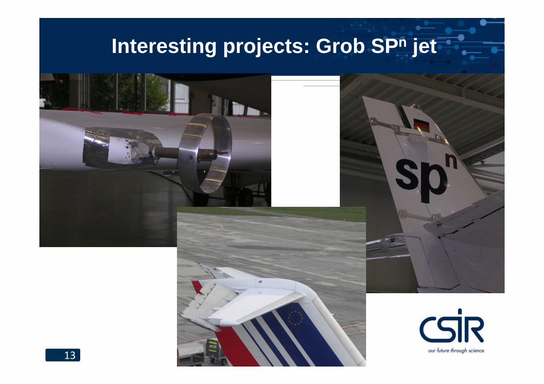
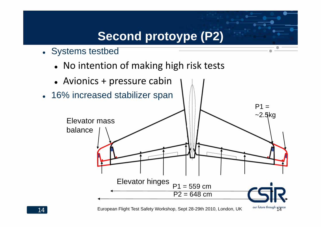
• Grob SPn jet. CSIR performed flutter flight testing of the first prototype, the second prototype crashed due to flutter.
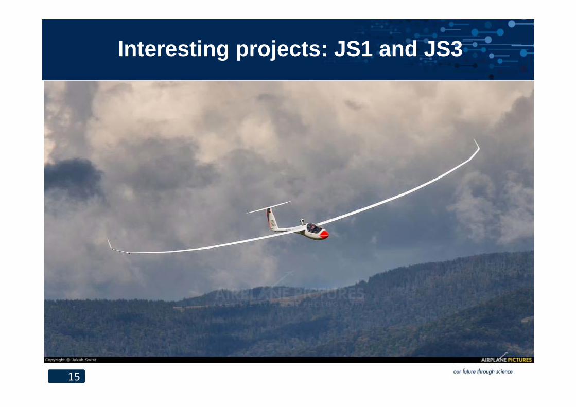
• JS1 / JS3. CSIR performed ground vibration testing and flutter analyses for these gliders.
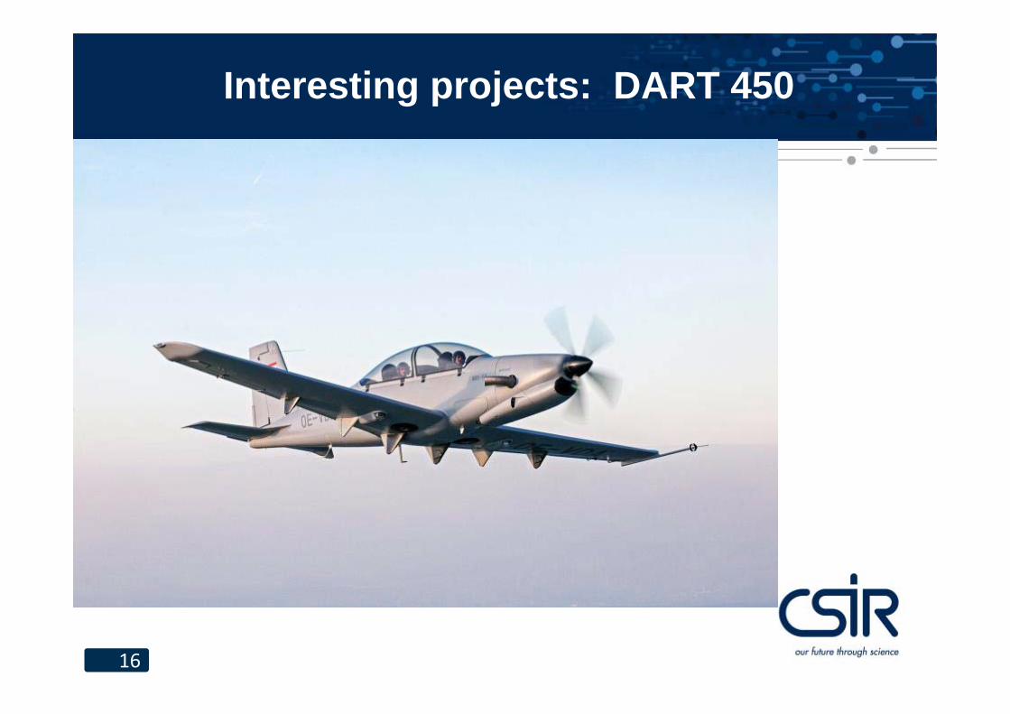
• Diamond DA42, DA62, Dart 450 The CSIR performed ground vibration tests, flutter analysis and flutter flight testing on these aircraft.
11
Interesting projects: Ravin 500
12
Interesting projects: Grob SPn jet
13
Interesting projects: Grob SPn jet
14 European Flight Test Safety Workshop, Sept 28-29th 2010, London, UK 14
Second protoype (P2) Systems testbed
No intention of making high risk tests Avionics + pressure cabin
16% increased stabilizer span
Elevator hingesP2 = 648 cmP1 = 559 cm
P1 = ~2.5kg
Elevator mass balance
15
Interesting projects: JS1 and JS3
16
Interesting projects: DART 450

17
Interesting projects: DA 42
18
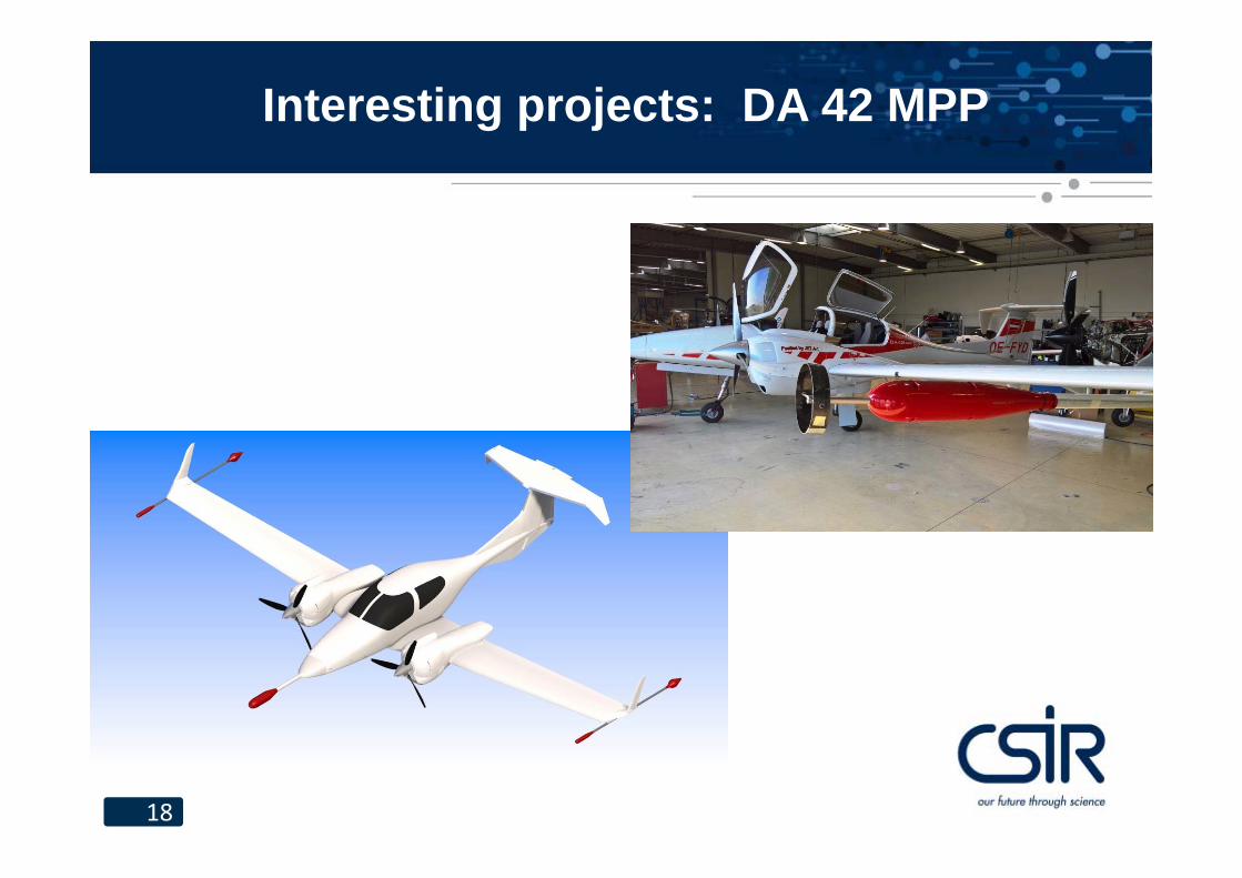
Interesting projects: DA 42 MPP
19
Interesting projects: T tails
• I took an interest in T-tail flutter after a remark that the DLM does not handle T-tails.
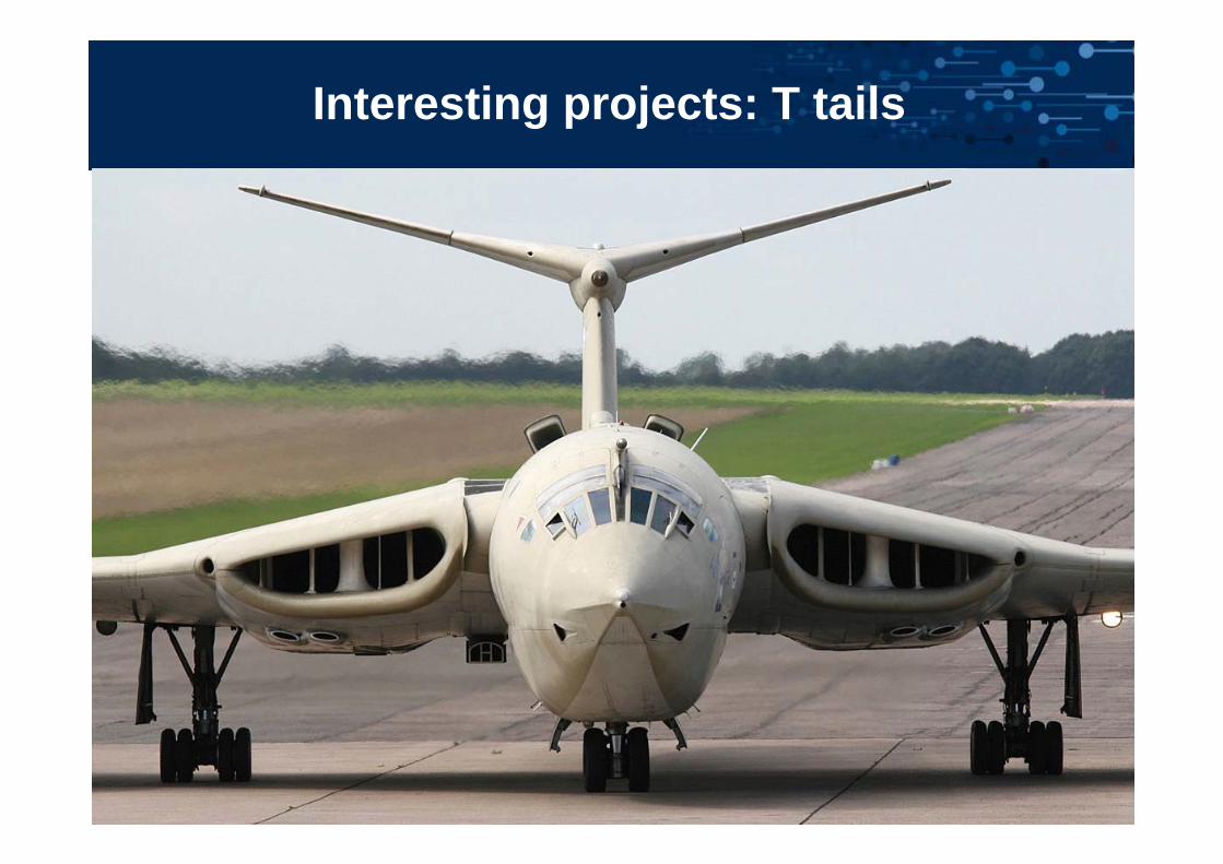
• The Handley Page Victor accident in 1954 drew attention to T-tail flutter, although the accident was probably due to other failures.
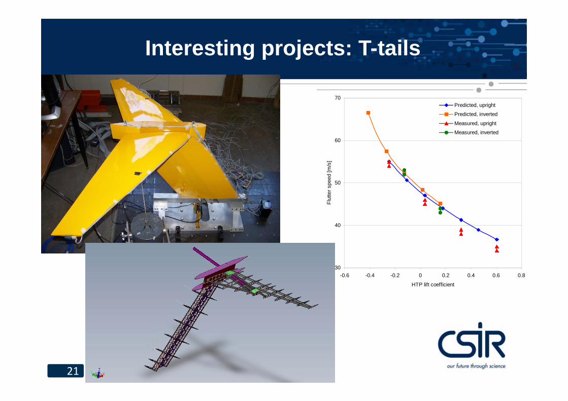
• A major issue is the effect of the trim load• I realised that quadratic mode shapes are essential for modelling T-tail flutter,
developed techniques for measuring them in a GVT and calculating them using FEA.
• I published an article along with Europeans using other methods. One of their test cases showed a-typical behaviour and they changed a sign in their method to obtain the (wrongly) expected behaviour. My method showed that their method was correct in the first place.
20
Interesting projects: T tails
21
Interesting projects: T-tails
30
40
50
60
70
-0.6 -0.4 -0.2 0 0.2 0.4 0.6 0.8
HTP lift coefficient
Flut
ter s
peed
[m/s
]
Predicted, upright
Predicted, inverted
Measured, upright
Measured, inverted
22
Interesting tools
• Flight flutter excitation systems.• Ground vibration test systems. • Actively controlled air supports for ground vibration testing.
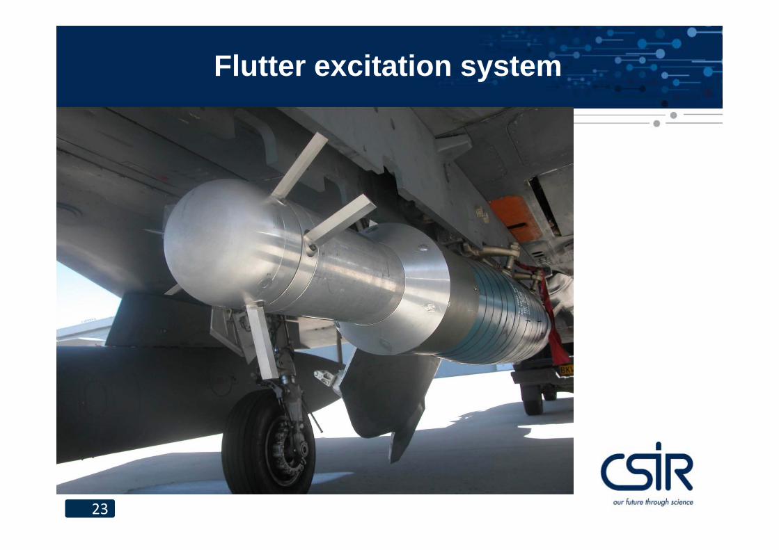
23
Flutter excitation system
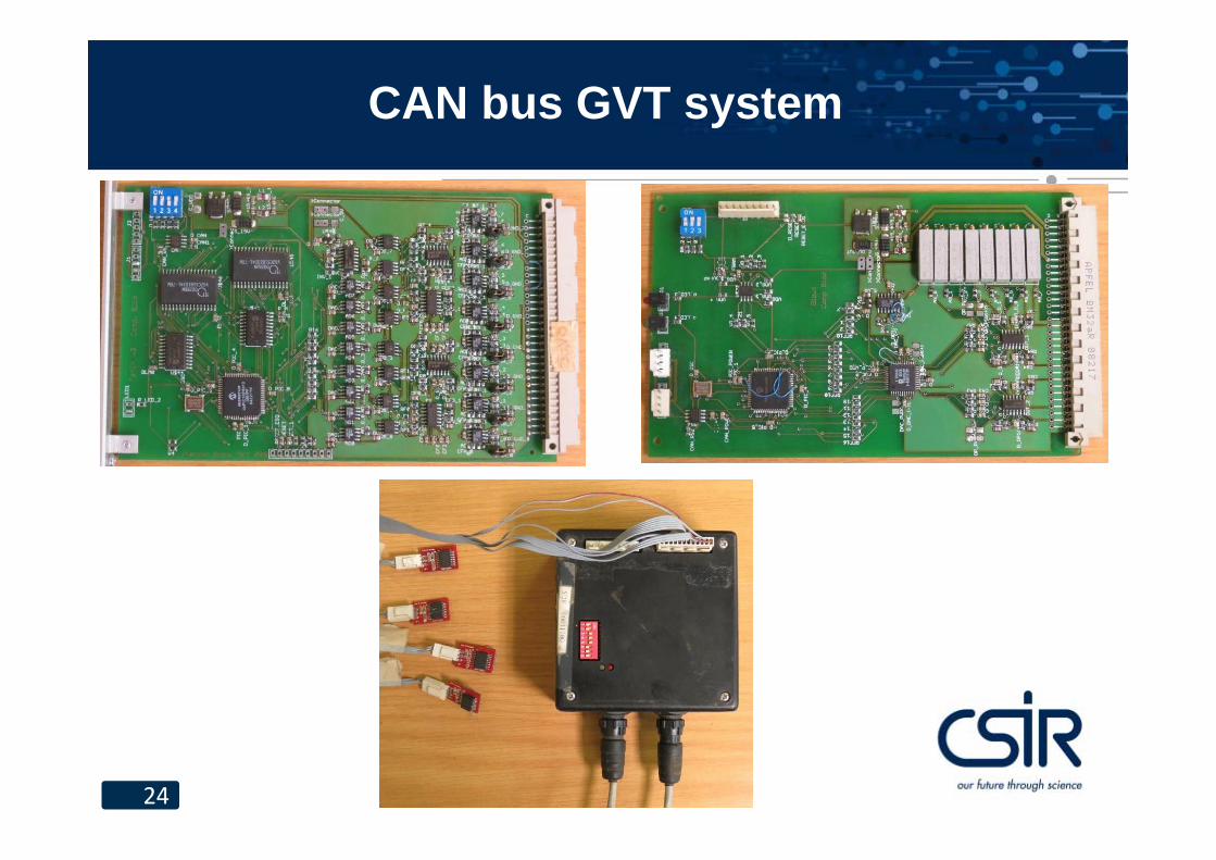
24
CAN bus GVT system
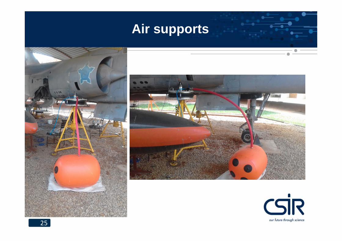
25
Air supports
26
Interesting people
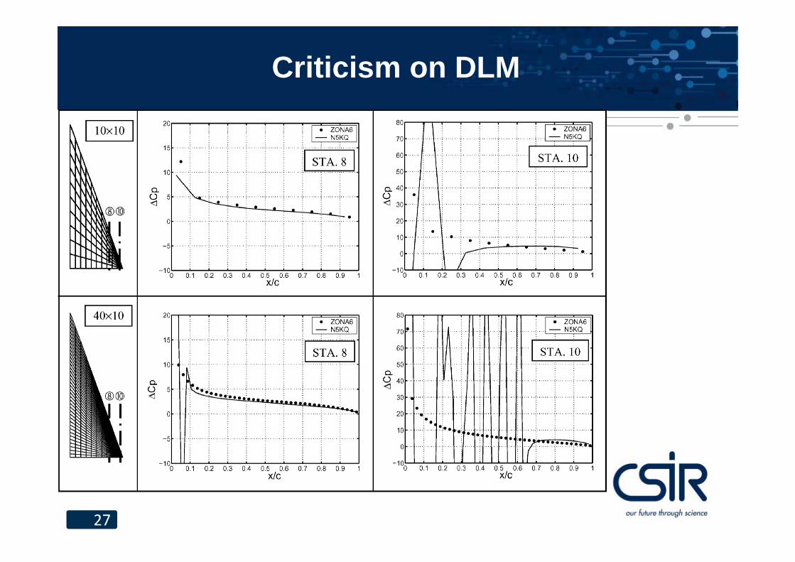
• Dr. Danny Liu. He criticised the doublet lattice method over a programming error in some codes. I tried to convince him that there was nothing wrong with the DLM as such, but never succeeded.
• Dr. Bill Rodden. I had an argument with him in 1996 regarding convergence of the DLM, but we became friends again. He encouraged me to write a DLM with a surface panel body model, which we still use and which I extended for T-tails. He facilitated fixing the error in the DLM in 2011 and asked me to write a piece on T-tail flutter for his book .
27
Criticism on DLM
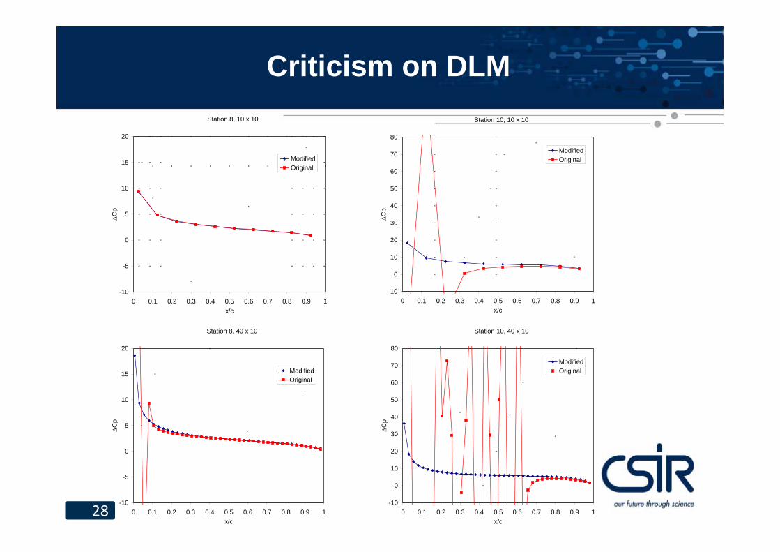
28
Criticism on DLMStation 8, 10 x 10
-10
-5
0
5
10
15
20
0 0.1 0.2 0.3 0.4 0.5 0.6 0.7 0.8 0.9 1x/c
C
p
ModifiedOriginal
Station 8, 40 x 10
-10
-5
0
5
10
15
20
0 0.1 0.2 0.3 0.4 0.5 0.6 0.7 0.8 0.9 1x/c
Cp
ModifiedOriginal
Station 10, 10 x 10
-10
0
10
20
30
40
50
60
70
80
0 0.1 0.2 0.3 0.4 0.5 0.6 0.7 0.8 0.9 1x/c
Cp
ModifiedOriginal
Station 10, 40 x 10
-10
0
10
20
30
40
50
60
70
80
0 0.1 0.2 0.3 0.4 0.5 0.6 0.7 0.8 0.9 1x/c
Cp
ModifiedOriginal
29
Flutter considerations for pilots and technicians
• Rules (made by people) and laws (of nature)• Mass balancing of controls• Free play in control systems.
Rules and laws
• RulesDo not exceed 120 km/h
Tolerance of 11 km/hUsually not caughtIf caught, bribing or discarding summons usually works
If convicted, choice of fine or prison term
• LawsDo not exceed flutter speed
No toleranceAlways caughtVery little chance of getting off the hook
No choice of punishment – entirely up to fate and usually severe

31
Rules and laws
If the law is so strict, why would there be transgressions?• Flutter speed is not precisely known• A rule is substituted for the law: VNE
• This rule is treated like any other
32
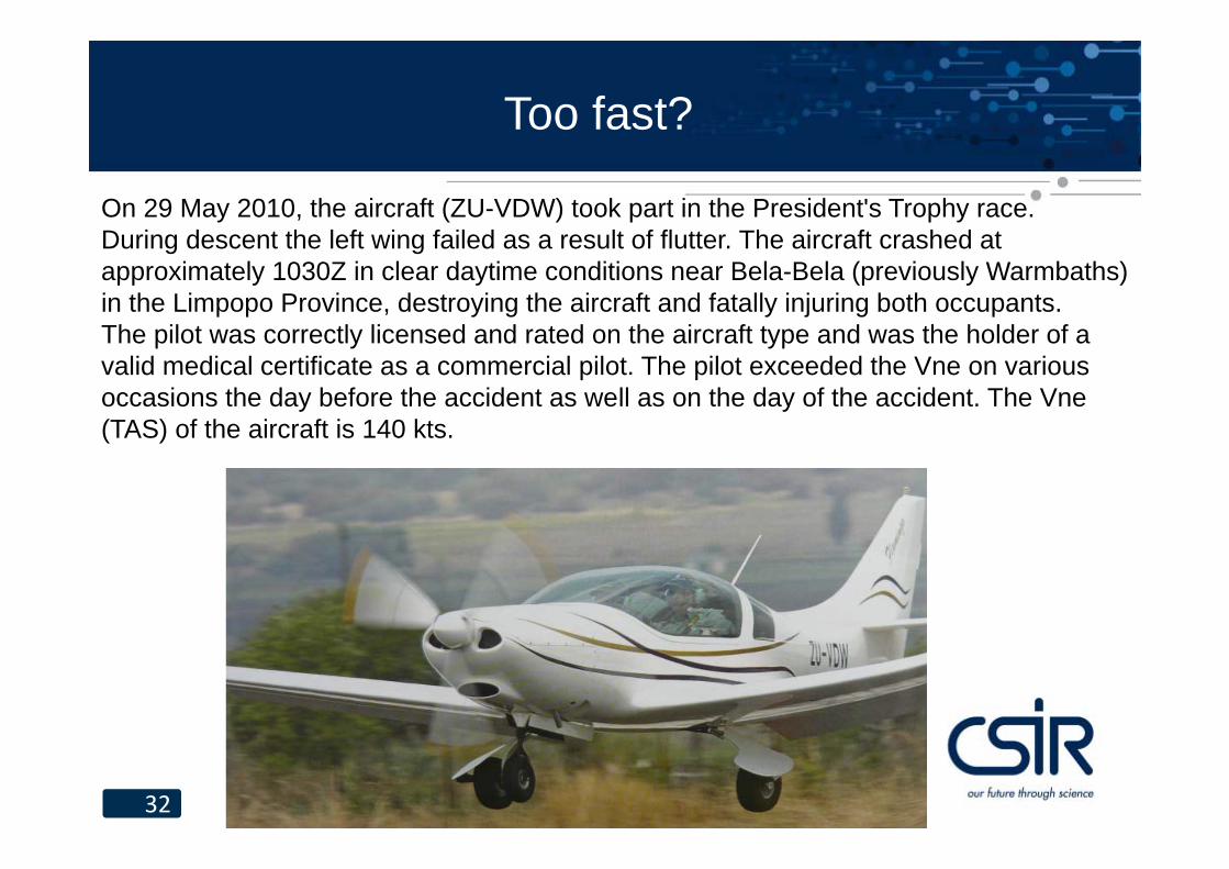
On 29 May 2010, the aircraft (ZU-VDW) took part in the President's Trophy race.During descent the left wing failed as a result of flutter. The aircraft crashed at approximately 1030Z in clear daytime conditions near Bela-Bela (previously Warmbaths) in the Limpopo Province, destroying the aircraft and fatally injuring both occupants.The pilot was correctly licensed and rated on the aircraft type and was the holder of a valid medical certificate as a commercial pilot. The pilot exceeded the Vne on various occasions the day before the accident as well as on the day of the accident. The Vne(TAS) of the aircraft is 140 kts.
Too fast?
33
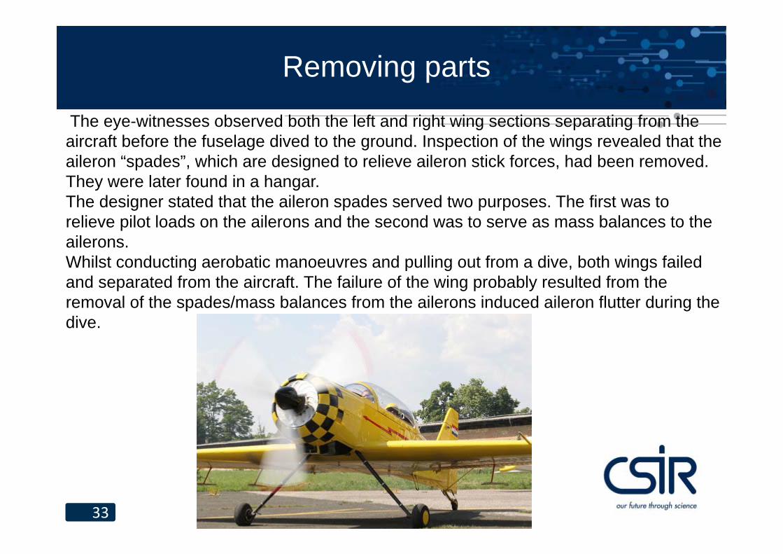
The eye-witnesses observed both the left and right wing sections separating from the aircraft before the fuselage dived to the ground. Inspection of the wings revealed that the aileron “spades”, which are designed to relieve aileron stick forces, had been removed. They were later found in a hangar. The designer stated that the aileron spades served two purposes. The first was to relieve pilot loads on the ailerons and the second was to serve as mass balances to the ailerons. Whilst conducting aerobatic manoeuvres and pulling out from a dive, both wings failed and separated from the aircraft. The failure of the wing probably resulted from the removal of the spades/mass balances from the ailerons induced aileron flutter during the dive.
Removing parts
34
Flutter check list for pilots
• Respect aircraft limitations• Pay attention to detail in pre-flight inspections,
especially control surface and tab free play (do you know what the limits are for your aircraft?) and loose rivets on hinges
• Do not remove things from or add things to an aircraft without fully understanding the implications
• Pay attention to cable tension in the control system. The effect of too low tension is similar to free play.
35
Conclusion
• Aeroelasticity is exciting despite the simplicity of the flutter equation.
• One should never be brave in the face of flutter, not even a pilot.
36
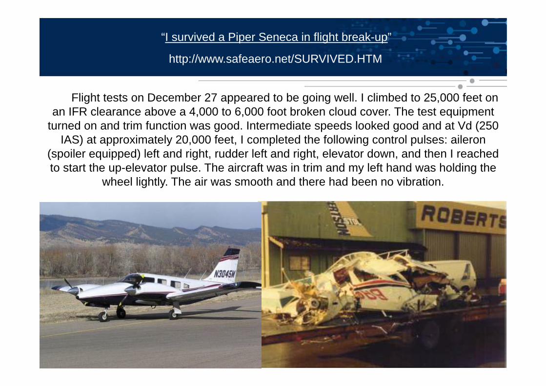
“I survived a Piper Seneca in flight break-up”
http://www.safeaero.net/SURVIVED.HTM
Flight tests on December 27 appeared to be going well. I climbed to 25,000 feet on an IFR clearance above a 4,000 to 6,000 foot broken cloud cover. The test equipment
turned on and trim function was good. Intermediate speeds looked good and at Vd (250 IAS) at approximately 20,000 feet, I completed the following control pulses: aileron
(spoiler equipped) left and right, rudder left and right, elevator down, and then I reached to start the up-elevator pulse. The aircraft was in trim and my left hand was holding the
wheel lightly. The air was smooth and there had been no vibration.
37
It was like an explosion, the elevator failure resulted in an extremely violent nose down tumbling. Both wings tore off, once outboard of the engine nacelle and again at the fuselage. The fuselage was ruptured, part of the tail section and rear door were gone, the fiberglass nose section was gone and the windshields were blown out. Negative Gs had me pinned against the cabin ceiling and the violent shaking had torn off my helmet. I had to protect my head with my hands to keep from being knocked out; the survival instinct had taken over. I knew I had to get out of there to stay alive, but I couldn't move and couldn't do anything but try to protect myself against the beating I was taking, As abruptly as it started, the violence stopped. It was smooth and calm, with a sense of slow rolling or tumbling. The cold air was blowing through the hulk of the fuselage (-40F). Seat belt off and through the cabin door, I opened my chute immediately, which could have been fatal. As my chute opened, an engine with a section of wing came by from above. I can still clearly see that engine in my mind. The prop was feathered and the engine was running. The total sequence of failure and getting out only took seconds, but it felt like minutes.
38
This was the first aircraft lost by Robertson in flutter testing. The FAA took a harder stand for more testing and complete evaluation by Robertson for flutter clearance. Prior to this loss, Robertson inspected and conformed only its modification and assumed that an airworthy aircraft would have all controls balanced and free play within limits. N33589 did not have the elevator tab free play measured before that test, but I firmly believe it was past its limits. On the walk-around inspection. I commented to the company inspector about the apparent amount of free play. We both agreed it was a common thing on Seneca’s. Hindsight is 20/20, and I know where I should have stopped that flight test. My recommendation for the owner of any aircraft is to assure that your aircraft is maintained properly. All control surfaces can be checked on a simple preflight. Free play limits are design limits with no margin of safety if they are exceeded. Replace bushings or install high tolerance bolts to stay within these limits. An AD is not issued unless the airworthiness is in question and this means an unsafe condition exists. These unsafe conditions are discovered ordinarily by you, the pilot. Pay attention and know your aircraft.
Sherman E, Hall (Former Robertson STOL Test Pilot & Chief Engineer)
39
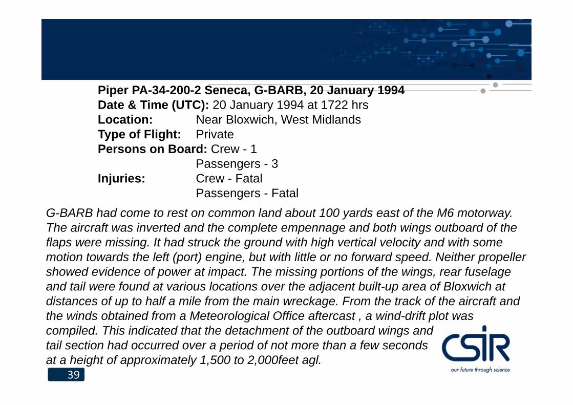
G-BARB had come to rest on common land about 100 yards east of the M6 motorway. The aircraft was inverted and the complete empennage and both wings outboard of the flaps were missing. It had struck the ground with high vertical velocity and with some motion towards the left (port) engine, but with little or no forward speed. Neither propeller showed evidence of power at impact. The missing portions of the wings, rear fuselage and tail were found at various locations over the adjacent built-up area of Bloxwich at distances of up to half a mile from the main wreckage. From the track of the aircraft and the winds obtained from a Meteorological Office aftercast , a wind-drift plot was compiled. This indicated that the detachment of the outboard wings and tail section had occurred over a period of not more than a few seconds at a height of approximately 1,500 to 2,000feet agl.
Piper PA-34-200-2 Seneca, G-BARB, 20 January 1994Date & Time (UTC): 20 January 1994 at 1722 hrsLocation: Near Bloxwich, West MidlandsType of Flight: PrivatePersons on Board: Crew - 1
Passengers - 3Injuries: Crew - Fatal
Passengers - Fatal
40
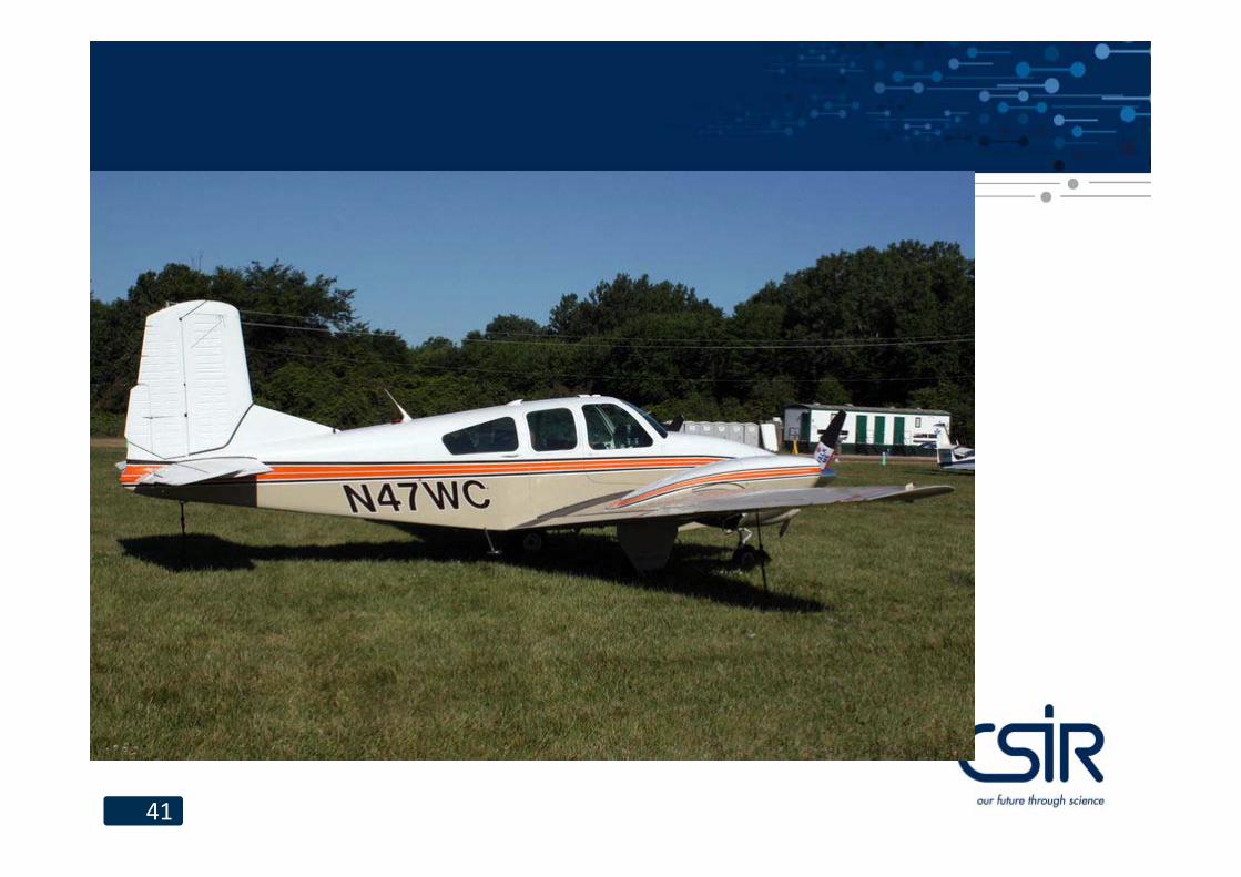
On 7 May 1995 an incident occurred involving a Beech 95A Travelair registration G-ATRC. This was reported in AAIB Bulletin 9/95. The Beech Travelair is a light twin, generally similar to the Seneca. In particular it has a large trim tab on the rudder.Approximately 10 minutes after taking off the pilot felt slight vibration through the rudder pedals. After applying right rudder the rudder jammed, causing the aircraft to sideslip. The vibration then became so severe that the pilot had difficulty in keeping his feet on the rudder pedals, and could not read the instruments. The sideslip continued, with the pilot unable to maintain height and experiencing pitch control difficulties. He also reported a stall warning at 120 kt IAS as power was reduced. The pilot declared an emergency and with assistance from ATC landed safely at a nearby airfield some 10 minutes later. He had eventually been able to level the aircraft using differential power at about700 ft. The pilot stated that he had been fortunate to regain a measure of control. Subsequent examination of the aircraft showed that the rudder trim tab actuating rod had fractured at its attachment to the rudder trim jack, which is mounted in the rear of the fin. This had left the major portion of the rod still attached to the tab.
41
42
Once the failure had occurred, the tab had been free to 'flutter' and to act as an uncontrolled 'servotab‘ giving rise to the violent pedal movement. On examination it was found that the failed end could be made to foul on the rudder in such a way that the tab was unable to return to centre, possibly accounting for the reported rudder jam. The failure was attributed to fatigue caused by incorrect assembly of the actuating rod. In discussion with the AAIB engineering inspector involved it was apparent how much difficulty this pilot had encountered and how little evidence on the structure there was of flutter-like damage.


