Context-Aware Indoor Navigation Fernando Lyardet 1 and Diego Wong Szeto 2 and Erwin Aitenbichler 2 1 SAP Research CEC Darmstadt, Darmstadt 64283, Germany 2 Darmstadt University of Technology, Hochschultrasse 10, 64289 Darmstadt, Germany Abstract. Over the past few years, several technological advances have been made to enable locating people in indoor settings, where way finding is some- thing we do on a daily basis. In a similar way as it happened with GPS and today’s popular outdoor navigation systems, indoor navigation is set to become one of the first, truly ubiquitous services that will make our living and work- ing environments intelligent. Two critical characteristics of human way finding are destination choice and path selection. This work focuses on the latter, which traditionally has been assumed to be the result of minimizing procedures such as selecting the shortest path, the quickest or the least costly path. However, this path approximations are not necessarily the most natural paths. Taking advantage of context-aware information sources, this paper presents an easy to deploy context- aware indoor navigation system, together with an efficient spatial representation, and novel approach for path adaptation to help people find their destination ac- cording to their preferences and contextual information. We tested our system in one building with several users to estimate first an assessment of preference val- ues, and later to compare how the paths suggested by our system correspond to those people would actually follow. The positive results of this evaluation confirm the suitability of our models and algorithms. 1 Introduction Many people, especially business travelers, are often confronted with the situation that they are visiting new places and have to figure out how to navigate to the places where they want to go. Because path finding is a frequently occurring real-world problem, many studies and applications have been done on this subject over the last years. These studies provide several interesting insights, e.g., primary criteria for human path selec- tion [1], or how people often prefer routes that are easier to describe and follow over routes that are optimal in a theoretical sense. An important indicator of perceived easier- to-follow routes are those with fewer instructions. In order to achieve this goal, different non-optimal algorithms that provide simpler paths were proposed, e.g., by Liu [2] and Richter [3]. However, these approaches were focused on street navigation, where the movement of people and vehicles follow the rules of street orientation. We believe an aspect that is hardly covered by current research literature is the need of adapting to the current situation of the user, and to the condition of the environment in indoor navigation applications. The variation of conditions people may encounter in environments such as airports, museums, corporate campuses, shopping malls, facto- ries, etc. is so diverse that they play a deciding role on the criteria to which path would be the one people would actually follow.
Transcript
Context-Aware Indoor Navigation
Fernando Lyardet1 and Diego Wong Szeto2 and Erwin Aitenbichler2
1 SAP Research CEC Darmstadt, Darmstadt 64283, Germany2 Darmstadt University of Technology, Hochschultrasse 10, 64289 Darmstadt, Germany
Abstract. Over the past few years, several technological advances have beenmade to enable locating people in indoor settings, where way finding is some-thing we do on a daily basis. In a similar way as it happened with GPS andtoday’s popular outdoor navigation systems, indoor navigation is set to becomeone of the first, truly ubiquitous services that will make our living and work-ing environments intelligent. Two critical characteristics of human way findingare destination choice and path selection. This work focuses on the latter, whichtraditionally has been assumed to be the result of minimizing procedures such asselecting the shortest path, the quickest or the least costly path. However, this pathapproximations are not necessarily the most natural paths. Taking advantage ofcontext-aware information sources, this paper presents an easy to deploy context-aware indoor navigation system, together with an efficient spatial representation,and novel approach for path adaptation to help people find their destination ac-cording to their preferences and contextual information. We tested our system inone building with several users to estimate first an assessment of preference val-ues, and later to compare how the paths suggested by our system correspond tothose people would actually follow. The positive results of this evaluation confirmthe suitability of our models and algorithms.
1 Introduction
Many people, especially business travelers, are often confronted with the situation thatthey are visiting new places and have to figure out how to navigate to the places wherethey want to go. Because path finding is a frequently occurring real-world problem,many studies and applications have been done on this subject over the last years. Thesestudies provide several interesting insights, e.g., primary criteria for human path selec-tion [1], or how people often prefer routes that are easier to describe and follow overroutes that are optimal in a theoretical sense. An important indicator of perceived easier-to-follow routes are those with fewer instructions. In order to achieve this goal, differentnon-optimal algorithms that provide simpler paths were proposed, e.g., by Liu [2] andRichter [3]. However, these approaches were focused on street navigation, where themovement of people and vehicles follow the rules of street orientation.
We believe an aspect that is hardly covered by current research literature is the needof adapting to the current situation of the user, and to the condition of the environmentin indoor navigation applications. The variation of conditions people may encounter inenvironments such as airports, museums, corporate campuses, shopping malls, facto-ries, etc. is so diverse that they play a deciding role on the criteria to which path wouldbe the one people would actually follow.
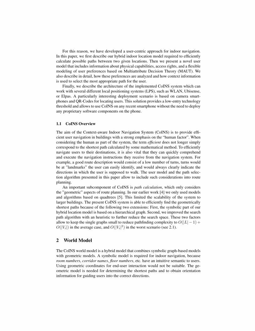
For this reason, we have developed a user-centric approach for indoor navigation.In this paper, we first describe our hybrid indoor location model required to efficientlycalculate possible paths between two given locations. Then we present a novel usermodel that includes information about physical capabilities, access rights, and a flexiblemodeling of user preferences based on Multiattribute Decision Theory (MAUT). Wealso describe in detail, how these preferences are analyzed and how context informationis used to select the most appropriate path for the user.
Finally, we describe the architecture of the implemented CoINS system which canwork with several different local positioning systems (LPS), such as WLAN, Ubisense,or Elpas. A particularly interesting deployment scenario is based on camera smart-phones and QR-Codes for locating users. This solution provides a low-entry technologythreshold and allows to use CoINS on any recent smartphone without the need to deployany proprietary software components on the phone.
1.1 CoINS Overview
The aim of the Context-aware Indoor Navigation System (CoINS) is to provide effi-cient user navigation in buildings with a strong emphasis on the “human factor”. Whenconsidering the human as part of the system, the term efficient does not longer simplycorrespond to the shortest path calculated by some mathematical method. To efficientlynavigate users to their destinations, it is also vital that they can quickly comprehendand execute the navigation instructions they receive from the navigation system. Forexample, a good route description would consist of a low number of turns, turns wouldbe at ”landmarks” the user can easily identify, and would always clearly indicate thedirections in which the user is supposed to walk. The user model and the path selec-tion algorithm presented in this paper allow to include such considerations into routeplanning.
An important subcomponent of CoINS is path calculation, which only considersthe ”geometric” aspects of route planning. In our earlier work [4] we only used modelsand algorithms based on quadtrees [5]. This limited the scalability of the system tolarger buildings. The present CoINS system is able to efficiently find the geometricallyshortest paths because of the following two extensions: First, the symbolic part of ourhybrid location model is based on a hierarchical graph. Second, we improved the searchpath algorithm with an heuristic to further reduce the search space. These two factorsallow to keep the single graphs small to reduce pathfinding complexity to O(|L| − 1)+O(|Vi|) in the average case, and O(|Vi|2) in the worst scenario (see 2.1).
2 World Model
The CoINS world model is a hybrid model that combines symbolic graph-based modelswith geometric models. A symbolic model is required for indoor navigation, becauseroom numbers, corridor names, floor numbers, etc. have an intuitive semantic to users.Using geometric coordinates for end-user interaction would not be suitable. The ge-ometric model is needed for determining the shortest paths and to obtain orientationinformation for guiding users into the correct directions.
Geometric 2D Room Model
Symbolic Building Model Geometric 3D Building Model
Symbolic Floor Model Geometric 2D Floor Model
Symbolic Geometric
Floor 3
Floor 2
Floor 1
ElevatorElevator Stairs
Floor 1
Floor 2
Floor 3
Corridor
Room A101
Room A102
Room A103
Room F101
Room F102
Room F103
...
Building
Floor
Room
Fig. 1. Hybrid world model of CoINS.
The world model serves two main purposes. First, it supports transformations be-tween geometric coordinates and symbolic locations and vice versa. When a 3D track-ing system is used that provides geometric coordinates to locate users, the model mustbe able to transform this coordinate into a symbolic location, such as a room number.The pathfinding algorithm of CoINS starts with the symbolic models to create a coarseplan of the route. After that, the geometric models are used for fine-planning. At thetransition between using symbolic and geometric models, the world model must alsosupport transforming symbolic into geometric coordinates.
Second, the model enables efficient pathfinding. The design of the CoINS worldmodel has been refined over several iterations to ensure that the search sets are as smallas possible and that the basic relations needed by the pathfinding algorithm can bechecked efficiently. In most cases, users will mostly move in two dimensions. Move-ments in the height dimension usually only occur when changing floors, which is mod-eled by using separate maps for each floor.
The world model of CoINS is shown in Figure 1. According to modeling level andmodel type, the world model consists of five parts:
Geometric Building Model: This is a detailed geometric 3D model of the entirebuilding. All other model parts are created at design time from this model. At run time,this model is not needed by the pathfinding algorithm of CoINS. However, if a 3D localpositioning system is used in the building, the model is needed to transform metriccoordinates to symbolic locations.
Geometric Floor Model: The floor model is a geometric 2D model of a singlefloor. Here, the term floor denotes some part of the building at the same level that isconnected. It does not necessarily have to correspond to the whole story of a building.On the same floor, users will only be able to move in two dimensions. When guiding a
l0
l1
l2
ЄE1
ЄE2ЄE3
a b c
bacb
aaЄE3
Fig. 2. A vertex-labeled universal hierarchical graph.
user on a floor, a 2D representation is sufficient. The reduction to 2D space simplifiespath calculation and increases performance significantly.
Geometric Room Model: The room model is a geometric 3D model of a room or acorridor. While it is not necessary to model rooms in detail, the geometry of corridors isimportant for finding shortest paths and to obtain direction information for navigation.
Symbolic Building Model: This is a symbolic graph-based model of the wholebuilding. Its nodes are floors and connecting structures, such as elevators and stairs.Each floor node holds a reference to its symbolic floor model.
Symbolic Floor Model: This is a symbolic graph-based model of a floor. Its nodesare rooms and corridors, connected by entrances and exits.
2.1 Graph-theoretical Model
This new model can be formalized using a recently specified graph class called univer-sal hierarchical graphs [6]. In [6], undirected universal hierarchical graphs have beenintroduced to calculate the topological entropy of such graphs. After this, the graphclass has been extended to the directed case [7]. Also, it was shown that these graphscan be efficiently classified by transforming them into certain property strings capturingimportant structural information.
In the following, we extend the definition given in [6] to vertex-labelled graphs andstate a special edge type specification.
be the unique vertex alphabet. lV : V −→ AUV represent the corresponding vertex
labeling function. L := {l0, l1, . . . , l|L|−1} defines the level set. |L| denotes its cardi-nality. L : V −→ L is a surjective mapping that is called a multi level function if itassigns to each vertex an element of the level set L. The graph U = (V,E) is called avertex-labelled universal hierarchical graph ⇔ its edge set can be represented by theunion E := E1 ∪ E2 ∪ E3. We specify the sets Ei as follows:
– E1 denotes the set of horizontal Across-edges. A horizontal Across-edge does notchange a level i.
– E2 denotes the set of edges which change exactly one level. .– E3 denotes the set of edges which overjump at least one level.
The set of undirected labelled universal hierarchical graphs is denoted by GLUHG.
As an example, Figure (4) shows an undirected labelled universal hierarchical graph.Here, it holds AU
V := {a, b, c}. For example, it is lV (v0,1) = a and lV (v2,4) = b.We see that our objects we deal with can be described by graphs U ∈ GLUHG. Therelationship to general graphs can be understood by recalling that an arbitrary graphis not necessarily hierarchical (the hierarchies must be induced). Generally, hierarchiescan be induced by selecting a distinct root and applying algorithms based on shortestpath, see, e.g., [8]. In our case, the hierarchy is given naturally because the building wewant to model is hierarchical.
In the following, we consider a special class G?LUHG of undirected labelled universal
hierarchical graphs such that E2 can be written as
where 1 ≤ i0 ≤ |V0|, 1 ≤ i1 ≤ |V1|, . . . , 1 ≤ i|L|−1 ≤ |V|L|− 1|. Speaking informally,that means we assume that there always exists at least one directed path starting fromat a vertex v0,i0 ∈ V and ending at v|L|−1,i|L|−1
∈ V (e.g. as it is the case with stairsconnecting floors). E?
2 is assumed to contain the remaining edges e ∈ E2. By using thisassumption, we easily derive the following assertion.
Theorem 1. Let U = (V,E) ∈ G?LUHG. The time complexity for finding an arbitrary
vertex v ∈ V is O(|L| − 1) + O(|Vi|).
Proof: Let U = (V,E) ∈ G?LUHG and arbitrary v ∈ V . Because there exists a path
P = (v0,i0 , v1,i1 , . . . , v|L|−1,i|L|−1), the worst case time complexity to calculate the
distance for vertices on this path is consequently O(|L| − 1). The time complexity forfinding a vertex on level i is O(|Vi|).
Corollary 1. Let U = (V,E) ∈ G?LUHG. In case there exists a vertex on each level i
which connects all remaining vertices on this level, the time complexity for finding anarbitrary vertex v ∈ V is O(|L| − 1) + O(1).
Theorem 2. Let U = (V,E) ∈ G?LUHG. Without the assumptions we made in Theo-
rem (1), the time complexity for finding an arbitrary vertex v ∈ V (starting from anothervertex) is O(|V |2).
Proof: Let U = (V,E) ∈ G?LUHG. We always assume that our graphs we deal with
are connected. To start from an arbitrary vertex and calculating the shortest distance toanother vertex, any shortest path algorithm can be used, e.g., Dijkstra-algorithm [8]. Forthis, the complete adjacency matrix must be parsed. But this requires time complexityO(|V |2).
AutoCAD 3ds Max / gmax
GtkRadiant
or Geometric3D Building
Model
Geometric3D FloorModels
Geometric 2D Room Models
Symbolic Floor Models
Symbolic Building Model
Fig. 3. Generation of the World Model.
2.2 Generation of the World Model
Figure 3 shows the generation of the CoINS world model and its parts.CoINS currently uses the Quake III map format [9] as input for the world descrip-
tions, since it is widely known and open source tools are available to create world de-scriptions. To create models for CoINS we have used the GtkRadiant kit [10] and Au-todesk Gmax [11] which allows us to import AutoCad drawings. A detailed discussionof describing the world using Quake maps, and the further processing required to mapinto 2D maps and identify rooms is presented in [4].
3 A Model for User Centric Adaptation
The user model we have developed and applied in our indoor navigation technologycombines three key aspects besides user identification data: physical capabilities, userpreferences, and location access rights.
3.1 Physical Capabilities
Physical capabilities are represented using the International Classification of Function-ing, Disability and Health (ICF) of the World Health Organization (WHO) [12]. TheICF has been developed by the WHO as a framework for measuring health and dis-ability, and proposes several types of qualifiers depending on the kind of impairmentevaluation. For body functions, a qualifier shows the presence of an impairment whichis measured on a five point scale: no impairment, mild, moderate, severe and complete.For the sake of simplicity, only voluntary leg movement-related functions involved inwalking are considered, although this model can be extended with other body functions.
3.2 Location Access Rights
Location access rights control the entrance of users to certain locations or places. InCoINS, a user can enter a location, if her access rights are available. This is modeledaccording to the Role Based Access Control (RBAC) model [13]. A user profile is aset of roles. Each role has a set of permissions that grant or restrict access to locations.User profiles and roles are managed within a session, in which user, profiles, roles andthe permissions are assigned. Concretely,
LOCATION: {Locations} PERMIT: ROLE × LOCATION 7→ PERMISSION
3.3 Preferences
The user preferences influence the selection of paths. These preferences describe thedesire or predisposition of a user in favor of something. In this case, the preferencestake the attributes of paths into account. Some examples of such attributes are temper-ature, luminosity, distance and crowdedness (Table 1). Since such preferences can bearbitrary, we need to measured them with a numerical scale so that the preference isquantifiable [14]. The range of the preference scale varies from 0 to 100, where 0 isequivalent to least and 100 the most preferable. In Table 2, we show different user pref-
(a)
Distance Assessment(m) Value0 10010 9530 8560 45
125 20200 3
(b)
Number Assessmentof turns Value
0 1005 80
10 4018 1
(c)
ADRT range Category AssessmentValue
0◦C - 10◦C Low 10011◦C - 20◦C Medium 4020◦C - higher High 0
Table 1. User preference assessment for (a) distance, (b) turns, and (c) temperature variation.
erences in their natural scales together with their upper and lower bounds. The upperbound values of Path length and number of turns is different for every building, there-fore an estimation was done by calculating the longest path possible in the buildingminimizing repetition of places. On the other hand, other maximum values such as pathcrowd density and variance are standards already documented elsewhere [15].
On certain occasions the construction of a natural scale is not possible. For instance,the beauty of a path is hard to measure with a scale, since it involves aspects such ascolor combination, layout, among others. For those scenarios, it is necessary to sub-stitute the attribute with other(s) that are easier to quantify. For instance, beauty canbe replaced with attributes like homogeneity of the locations layouts and the height ofwalls.
3.4 Modeling User Preferences with Multiattribute Utility Theory
This model presents a Multiattribute Utility Theory (MAUT)-based architecture thatenables decision making according to user interests (Table 3). Each user has a differentsetting of preferences, and each with a different priority to the user. The strength ofa preference is given by an assessment function f . Let’s define F as the set of allassessment functions f . Nevertheless, every user has different preferences when faced
Fig. 4. The first curve shows an example of a polynomial approximation with distance values inmeters. Preferences can also be categorized as ”low”, ”medium” and ”high”, resulting in the stepfunction on the right.
Attribute Lower bound Upper boundPath length (m) 0 3780Number of turns 0 246Number of visual aids 0 75Acum. temperature deviation (◦C) 0 100Path crowd density (persons/m2) 0 6Crowd density variance (persons/m2)2 0 0.2
Table 2. Natural scales of path preference attributes.
in several different situations. As a result, an assessment function f holds if certainconditions apply. Let’s define E as our set of possible events e. An event e represents asituation of the user like for instance, the user is carrying heavy luggage or the locationis on fire.
Depending on the application domain, every assessment function f quantifies thepreference strength of some criterion c. These criteria comprise several aspects con-cerning the application. In the domain of indoor navigation, criteria such as path length,number of turns or crowdedness are relevant.
Each of these criteria may also be subject to user specific trade-off behavior. Oneway to solve this is to assign priority weights to the assessment functions, which isconventionally done in standard Multiattribute Utility Theory (MAUT) techniques.
F = {f | f is an assessment function} COND = {STATE, ACTIVITY,E = {e | e is an event} LOCATION, TIME}X = {x | x can be assessed with some f ∈ F } STATE = { happy, busy, available, . . .}
Table 3. Multiattribute Utility Theory definitions, and attribute examples.
Even though preference strength is measured by assessment functions, the prefer-ence priority can change when events occur. Someone walking in an airport with emptyhands could probably care less about the path length than after picking his luggage.In that situation, the importance weight of the path length criteria increases from notbeing empty handed and having luggage. Therefore, preference priority weights shouldbe adjustable to different circumstances when events happen. An Event Listener noti-fies the client about an incoming event ei (1). Upon receiving the event notification, theclient updates the preference functions by forwarding the notification message to everycriteria. As a result, every criteria knows what events affects them and by how much thepreference priority is increased or decreased.
4 Path Calculation and Selection
To select the most suitable path for a specific user we use the Simple Multi-AttributeRating Technique (SMART). Under this technique, every path can be described by in-dividual preference attributes and through the value functions of each single attribute,the preference strength can be measured.
The process of decision making can be influenced by the user’s consideration ofwhat attributes are more important or relevant to him. For this reason, importanceweights are given to attributes in order to model this kind of situation. The importanceweight alters the output of an attribute’s value function.
The measured preference strength of every single attribute of a path can be aggre-gated to return an overall path evaluation value. This resulting value will be later usedto compare against other possible paths.
4.1 Assessment of Preferences with Simple Multiattribute Rating Technique(SMART)
Our optimal path selection problem using SMART is formalized as follows:Let P be the set of all feasible paths, then P = {p|p is a path over the location model}
and an all attributes with importance weights wn and value functions vn. Then, the op-timal path p ∈ P maximizes
eval(p) = aggregate(wi(vi(ai(p)))) for i = 1,. . . , number of attributesThe following five steps describe how the path selection using the SMART method
is conducted:
1. Define the feasible paths and attributes for evaluation. All feasible paths aregenerated. Given that locations are connected as a graph in the location model,all paths can be generated by traversing the graph using a depth first search, A∗
or Dijkstra. User constraints (e.g. physical disabilities) can be used at this stageto avoid traversing unnecessary paths thus filtering them out from the selectionprocess.
2. Assign the importance weights to the attributes. The importance of attributesto the user are established by assigning importance weights to attributes. Theseweights are normalized,which means in this case that the sum of all weights equals
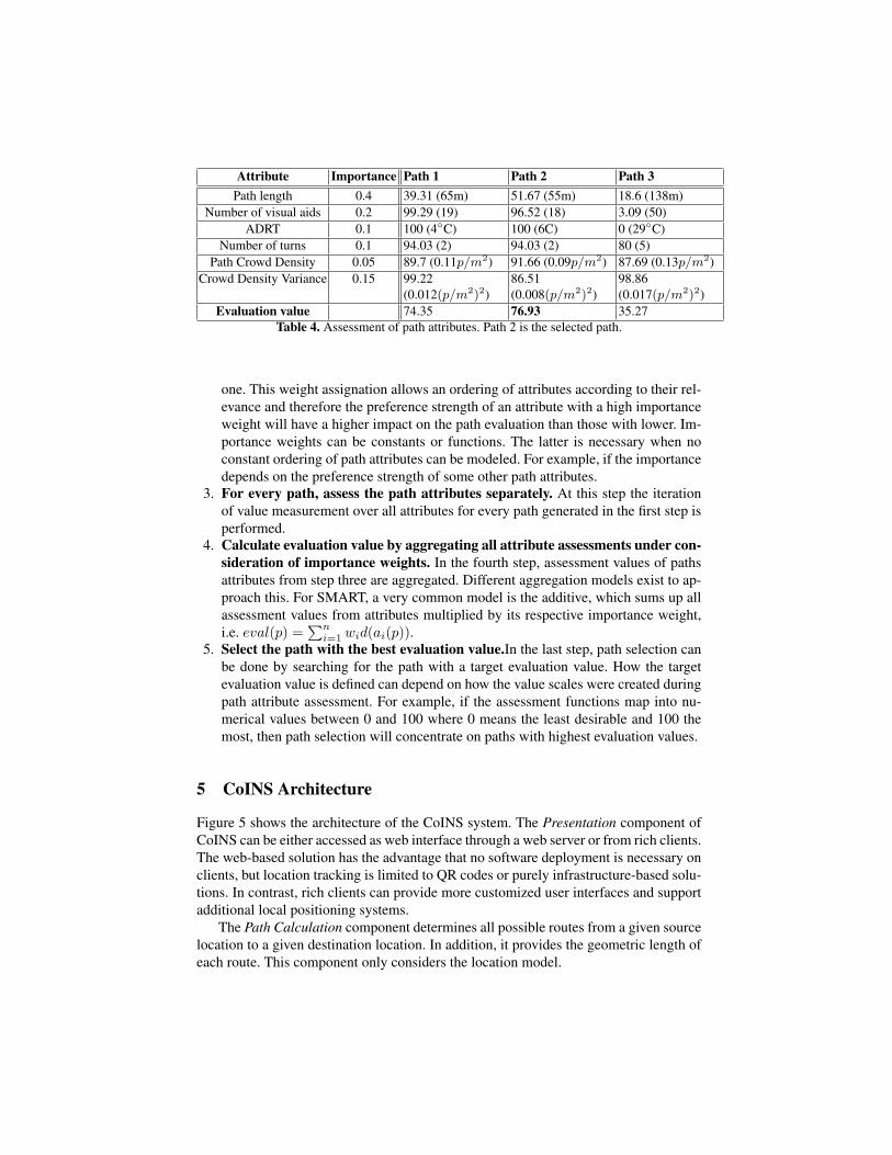
Number of visual aids 0.2 99.29 (19) 96.52 (18) 3.09 (50)ADRT 0.1 100 (4◦C) 100 (6C) 0 (29◦C)
Number of turns 0.1 94.03 (2) 94.03 (2) 80 (5)Path Crowd Density 0.05 89.7 (0.11p/m2) 91.66 (0.09p/m2) 87.69 (0.13p/m2)
Crowd Density Variance 0.15 99.22(0.012(p/m2)2)
86.51(0.008(p/m2)2)
98.86(0.017(p/m2)2)
Evaluation value 74.35 76.93 35.27Table 4. Assessment of path attributes. Path 2 is the selected path.
one. This weight assignation allows an ordering of attributes according to their rel-evance and therefore the preference strength of an attribute with a high importanceweight will have a higher impact on the path evaluation than those with lower. Im-portance weights can be constants or functions. The latter is necessary when noconstant ordering of path attributes can be modeled. For example, if the importancedepends on the preference strength of some other path attributes.
3. For every path, assess the path attributes separately. At this step the iterationof value measurement over all attributes for every path generated in the first step isperformed.
4. Calculate evaluation value by aggregating all attribute assessments under con-sideration of importance weights. In the fourth step, assessment values of pathsattributes from step three are aggregated. Different aggregation models exist to ap-proach this. For SMART, a very common model is the additive, which sums up allassessment values from attributes multiplied by its respective importance weight,i.e. eval(p) =
∑ni=1 wid(ai(p)).
5. Select the path with the best evaluation value.In the last step, path selection canbe done by searching for the path with a target evaluation value. How the targetevaluation value is defined can depend on how the value scales were created duringpath attribute assessment. For example, if the assessment functions map into nu-merical values between 0 and 100 where 0 means the least desirable and 100 themost, then path selection will concentrate on paths with highest evaluation values.
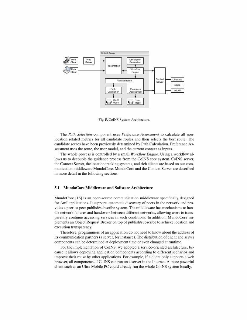
5 CoINS Architecture
Figure 5 shows the architecture of the CoINS system. The Presentation component ofCoINS can be either accessed as web interface through a web server or from rich clients.The web-based solution has the advantage that no software deployment is necessary onclients, but location tracking is limited to QR codes or purely infrastructure-based solu-tions. In contrast, rich clients can provide more customized user interfaces and supportadditional local positioning systems.
The Path Calculation component determines all possible routes from a given sourcelocation to a given destination location. In addition, it provides the geometric length ofeach route. This component only considers the location model.
WebServer
Ubisense
Elpas
WLAN
ContextServer
CoINS Server
Presentation
WorkflowEngine
DescriptionGeneration
Path Calculation
WebClient
RichClient
WorldModel
UserModel
PreferenceAssessment
Path Selection
Fig. 5. CoINS System Architecture.
The Path Selection component uses Preference Assessment to calculate all non-location related metrics for all candidate routes and then selects the best route. Thecandidate routes have been previously determined by Path Calculation. Preference As-sessment uses the route, the user model, and the current context as inputs.
The whole process is controlled by a small Workflow Engine. Using a workflow al-lows us to decouple the guidance process from the CoINS core system. CoINS server,the Context Server, the location tracking systems, and rich clients are based on our com-munication middleware MundoCore. MundoCore and the Context Server are describedin more detail in the following sections.
5.1 MundoCore Middleware and Software Architecture
MundoCore [16] is an open-source communication middleware specifically designedfor AmI applications. It supports automatic discovery of peers in the network and pro-vides a peer-to-peer publish/subscribe system. The middleware has mechanisms to han-dle network failures and handovers between different networks, allowing users to trans-parently continue accessing services in such conditions. In addition, MundoCore im-plements an Object Request Broker on top of publish/subscribe to achieve location andexecution transparency.
Therefore, programmers of an application do not need to know about the address ofits communication partners (a server, for instance). The distribution of client and servercomponents can be determined at deployment time or even changed at runtime.
For the implementation of CoINS, we adopted a service-oriented architecture, be-cause it allows deploying application components according to different scenarios andimprove their reuse by other applications. For example, if a client only supports a webbrowser, all components of CoINS can run on a server in the Internet. A more powerfulclient such as an Ultra Mobile PC could already run the whole CoINS system locally.
5.2 The Mundo Context Server
The Mundo Context Server [17] is responsible for transforming raw sensor readingsinto information that is meaningful to applications. It is an application-independent andreusable component that aims to decouple applications from sensors such that sensorsbecome interchangeable and that new sensors can be added without requiring to changeapplications. The context server provides the following functionality:
– Interpreting data received from sensors and transforming this data into a commonrepresentation.
– Maintaining a geometric world model of the environment and supporting geometricoperations and queries.
– Inferring “higher-level” context from “lower-level” context.– Notifying applications when certain context properties change.– Storing histories of sensed and inferred context and supporting queries in those
histories.
CoINS uses the Context Server to track the locations of users. Because the ContextServer provides an abstraction layer above the physical sensors, CoINS can use stan-dardized queries and does not have to be aware of the underlying sensor technology.The Context Server is based on the notion of widgets to process context information. Aprocessing chain for a location sensor usually consist of the following steps:
1. Sensor: The first widget in the chain obtains the raw sensor data. In most cases,it is a MundoCore Subscriber that receives messages from a remote sensor in thenetwork.
2. Normalization: Normalization transforms a system-specific message into a nor-malized, system-neutral message. The classes of normalized messages are com-posed by “multiple inheritance” and implement an ID part and a location part.
3. Transformation: This step handles entity/ID transformations, e.g. to translate fromtags to users, or from base stations to rooms, or positions between coordinate sys-tems.
4. Inference: This step infers relations from messages. A relation typically consistsof two entities and describes a relationship between those two entities. Relationsare expressed as RDF statements.
5. Storage: The relation store stores relations and is based on the Tuplespace concept.6. Query/Subscription: Applications can query the relation store or subscribe to the
store. A query operation returns all relations matching a specified pattern. When anapplication subscribes to the store, it will be notified each time a tuple matching thespecified pattern is inserted into the space.
The current implementation of the CoINS system can work with the following trackingsystems:
– Ubisense: Ubisense [18] is an UWB-based high-resolution 3D tracking system.For this system, the processing chain consists of a normalization to a common rep-resentation for 3D tracking systems, coordinate system transformation, tag-to-userID mapping, transformation to symbolic coordinates using the Geometric BuildingModel.
– Elpas: Elpas [19] is a badge-based system that combines IR, LF, and RF. It cancover entire buildings and depending on the amount of infrastructure deployed,its accuracy varies between 25m and 2m. Elpas provides symbolic location in asystem-specific format. The processing chain consists of a normalization to a com-mon representation for badge-based systems, tag-to-user ID mapping, and sensor-to-room ID mapping.
– WLAN: WLAN-based tracking [20] can utilize WLAN infrastructures that oftenalready exist. WLAN-based systems can reach an accuracy of about 2-3m, giventhat the necessary RSS fingerprint maps are accurate.
– QR: Quick Response (QR)-Codes are two-dimensional barcodes that were stan-dardized by ISO in the year 2000 (ISO/IEC 18004). To date, QR reading softwareis available for almost any smartphone. QR codes can be used to create physi-cal world hyperlinks: A user having a camera phone can scan the image of a QRCode causing the phone’s browser to launch and redirect to the programmed URL.When using QR codes as a location source, the physical location of the QR codeis encoded into the URL. The context server is then used to map location codes tosymbolic locations.
The Context Server would support even more tracking systems. However, thesesystems either cover areas too small for indoor navigation applications (IRIS [21]) orthey are not accurate enough (Cellphone tracking [22]).
6 User Guidance
6.1 Customizable Guidance Process
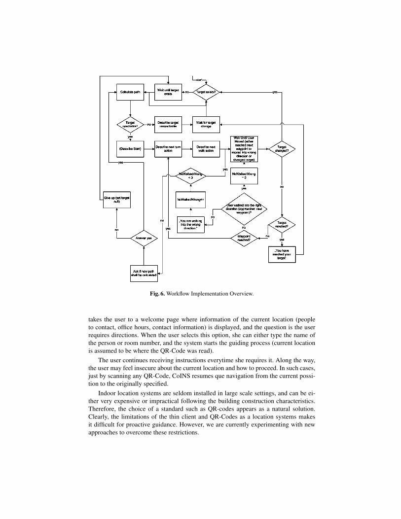
The CoINS system decouples the process of guiding a user by including a small, em-beddable workflow engine called Micro workflow [23]. In this way, both the support-ing services and the process of indoor user guidance can be further modified. Anotheradvantage is that this approach also enforced further separations of responsibilities inorder to allow a possible change of the workflow engine if required. Figure 6 shows theimplementation of a guidance workflow.
6.2 Giving Directions to The User
Different techniques and requirements have been studied for guiding users indoors withmobile platforms [24, 25]. Guiding techniques includes floor maps, schemas, and spatiallandmarks [26] together with their spatial relationships to help build a ”mental trip” onthe guided user.
The user guidance in the current version of CoINS is realized through a visualmodality, where instructions are displayed in the user’s terminal. We have so far de-veloped 2 different versions for the user terminal. The latest one is a ”thin” client, inorder to support the common situation where no software deployment can be done onthe user terminal.
In a typical scenario, a user enters the building and points with the mobile’s camerato any of the QR-Codes available in every door (Figure 7). A URL is encoded that
Fig. 6. Workflow Implementation Overview.
takes the user to a welcome page where information of the current location (peopleto contact, office hours, contact information) is displayed, and the question is the userrequires directions. When the user selects this option, she can either type the name ofthe person or room number, and the system starts the guiding process (current locationis assumed to be where the QR-Code was read).
The user continues receiving instructions everytime she requires it. Along the way,the user may feel insecure about the current location and how to proceed. In such cases,just by scanning any QR-Code, CoINS resumes que navigation from the current possi-tion to the originally specified.
Indoor location systems are seldom installed in large scale settings, and can be ei-ther very expensive or impractical following the building construction characteristics.Therefore, the choice of a standard such as QR-codes appears as a natural solution.Clearly, the limitations of the thin client and QR-Codes as a location systems makesit difficult for proactive guidance. However, we are currently experimenting with newapproaches to overcome these restrictions.
Fig. 7. A user scanning a QR-Code.
7 Evaluation
Two different experiments have been carried out to study the paths people follow toreach a given destination in indoor settings. The purpose of the first evaluation wasto gather information to find a common profile for the experiment, that is, a set ofassessment functions (three of them are shown in table 1(a),(b) and (c)) and a ranking ofthe different criteria to estimate their weight in the path selection assessment procedure(shown in table 4).
For the first experiment 8 subjects where scheduled, all of them familiar with thePiloty Building at the University of Darmstadt, a 4-story building, that offers in everyfloor five different stairs and 2 elevators to change floors (see figure 5). A set of pairsof origins and destinations were carefully selected, and the subjects were asked to carryout simple tasks that implied walking between the selected destinations(e.g. ”You needto pick up a form in office XXX”, ”Take the form to Mr. YYY in office XYZ”, ”Go tothe library”,”Get a Coffee at the Bistro”, etc.). To start the experiment, subjects weremet at the origin for their assigned route and then were read the appropriate directions.Afterwards, the subjects began walking to the given destinations as a part of the assign-ments given. The routes every participant followed were recorded in separate maps ofthe area, and all possible paths were coded to record every time a particular path wasfollowed. Subjects then completed a questionnaire on the criteria they used in selectinga path.
The second experiment involved 9 subjects (5 female, 4 male) that did not partic-ipate in the first experiment. We chose the same set of destinations as in the first ex-periment, and assigned the same tasks to the subjects, following the first experiment’sprocedure. We also used the data and user preference profile information gathered dur-ing the first experiment for the algorithm to calculate for every participant the suggestedpath, in order to take into account the contextual characteristics at the moment wherethe experiment would take place, and compare it to the one actually followed by thesubject. The results of this first evaluation of the system are shown in table 6. Theseresults suggests that the proposed paths by system matches those chosen by people ata particular contextual setting. In table 5 we show an schema of the building, with theproposed paths by the system and the alternatives performed by the users. Although
encouraging, this study must also be performed in our future work in large indoor sce-narios such as airports, where users may have more options of movement according tothe context.
(a) (b)
A to B B to C C to D D to EPath Path Path Path
Subj. M/F Chosen Chosen Chosen Chosen1 M Y Y Y Y2 M Y Y Y Y3 M Y Y N Y4 F N Y Y Y5 F Y Y Y Y6 F Y Y N Y7 F Y Y Y Y8 M N Y N Y9 F Y Y Y Y
Table 5. (a) Shows the structure of the Piloty building, and the paths proposed for evaluation.(b)Table shows for each participant and path, whether the path followed by the subject matchesthe path proposed by the system.
Path 1 Path 2 Path 3 Path 4 Σ
] Dijkstra’s generated Paths 24 9 24 57] CoINS heuristic’s generated Paths 9 9 1 1Users that followed path as predicted 7 9 6 9 31Users that followed a different path 2 0 3 0 5
Table 6. Generated paths and evaluation results.
In Table 6 we show the result of the reduced search space done by the heuristicimplemented in CoINS allowed a reduction of potential paths to be analyzed of morethan 82% (114 found by the general Dikjstra vs. 20 from CoINS spearch space reduction+ Dijkstra). The results of the user behavior are encouraging: more that 86,1% of theusers actually followed the paths suggested by the algorithm.
8 Related Work
Human way finding has been studied from many different perspectives. Understandinghuman way finding and navigation has been done in architecture and geography studies.How human convey information to guide and orient others with verbal instructions [27].Different studies have shown the relative importance of path optimality: people wouldaccept a less optimal (in terms of distance) path, in favor of routes that are potentially
easier to describe or follow. Perhaps the closest related system is by Tsetsos et al. [28]presenting Ontonav , a system that introduces the use of ontologies in indoor navigationto describe and reason over the user preferences, and annotate the world model, in orderto determine the path users must follow. Finally, Yao et al. [29] also proposes a naviga-tion system using geo-coded QR-codes for individuals with cognitive impairments.
Other relevant systems are Drishti developed by Lisa Ran, Sumi Helal and SteveMoore in [30]. Drishti is an integrated indoor/outdoor navigation system for visuallyimpaired people that uses commercial off the shelf soft- and hardware. And finally theNavio Project [31] from the Vienna University of Technology, a pedestrian navigationsystem in mixed indoor and outdoor environment. It addresses several important aspectslike positioning, route planning, and communication of pedestrian navigation services.
9 Summary and Future Work
We have developed CoINS, a context-aware indoor navigation system with efficientroute planning. A key element to the efficient calculation of routes between two givenlocations is the hybrid location model presented in this paper. We have also discussedthe application of QR codes for easy to deploy indoor navigation, without having todeploy any specific software on the end-user terminal. Finally, the selection of the mostsuitable path is done through a process of assessing user preferences according to thecontext information.
As future work we plan to add automatic customization of the preferences to eachuser, as well as the set of preferences to be evaluated and the ranking among them.On the technology side, we will extend the current web-based user client to a richapplication, and take advantage of compass-enabled smartphones.
References
1. Golledge, R.G.: Path selection and route preference in human navigation: A progress report.In: COSIT. (1995) 207–222
2. Liu, B.: Intelligent Route Finding: Combining Knowledge, Cases and an Efficient SearchAlgorithm. In: Proceedings of ECAI96, 12th European Conference on Artificial Intelligence,John Wiley & Sons, Ltd (1996) 149–155.
10. GTK: Radiant. http://www.qeradiant.com (March 2006) last visited: 03.07.2008.11. Autodesk: Gmax. http://www.autodesk.com/gmax (2008) last visited: 03.07.2008.12. World Health Organization: International Classification of Functioning, Disability and
Health. http://www.who.int/classifications/icf/en last visited: 03.07.2008.13. Ferraiolo, D., Kuhn, R.: Role-Based Access Control. In: Proceedings of the 15th National
Computer Security Conference. (1992) 554–56314. Edwards, W., von Winterfeldt, D.: Decision Analysis And Behavioral Research. Cambridge
University Press (1986)15. Neufert, E., Neufert, P.: Architect’s Data. Blackwell Science (2000)16. Aitenbichler, E., Kangasharju, J., Muhlhauser, M.: MundoCore: A Light-weight Infrastruc-
ture for Pervasive Computing. Pervasive and Mobile Computing 3(4) (August 2007) 332–361 doi:10.1016/j.pmcj.2007.04.002.
17. Aitenbichler, E., Lyardet, F., Muhlhauser, M.: Designing and Implementing Smart Spaces.Cepis Upgrade VIII(4) (August 2007) 31–37
18. Ubisense: Homepage. The Smart Space Company. http://www.ubisense.net/ (last visited:03.07.2008) (2008)
19. Visonic Technologies: Elpas. http://www.visonictech.com/elpas.html (2007) last visited:03.07.2008.
20. Song, Y.: In-House Location Tracking. Master’s thesis, Darmstadt University of Technology(2002)
21. Aitenbichler, E., Muhlhauser, M.: An IR Local Positioning System for Smart Items and De-vices. In: Proceedings of the 23rd IEEE International Conference on Distributed ComputingSystems Workshops (IWSAWC03), IEEE Computer Society (May 2003) 334–339
22. Hartl, A.: A Provider-Independent, Proactive Service for Location Sensing in Cellular Net-works. In: GTGKVS Fachgesprach (Online Proceedings). (2005)
23. Manolescu, D.: Workflow Enactment with Continuation and Future Objects. In: OOP-SLA’02, ACM (November 2002)
24. Butz, A., Baus, J., Kruger, A., Lohse, M.: A Hybrid Indoor Navigation System. In: IUI2001:International Conference on Intelligent User Interfaces, New York, ACM Press (January2001) 25–32
25. Fraunhofer: Messe Navigator. http://www.iis.fraunhofer.de/ec/navigation/indoor/projekte/messe(accessed at April 2006)
26. Sorrows, M., Hirtle, S.: The Nature of Landmarks for Real and Electronic Spaces. In Freksa,C., Mark, D.M., eds.: COSIT ’99. Volume 1661., Springer (1999) 37–50
27. Streeter, L.A., Vitello, D., Wonsiewicz, S.A.: How to Tell People Where to Go: ComparingNavigational Aids. International Journal of Man-Machine Studies 22(5) (1985) 549–562
28. Tsetsos, V., Anagnostopoulos, C., Kikiras, P., Hasiotis, P., Hadjiefthymiades, S.: A Human-Centered Semantic Navigation System for Indoor Environments. Pervasive Services, 2005.ICPS ’05. Proceedings. International Conference on (July 2005) 146–155
29. Chang, Y.J., Tsai, S.K., Chang, Y.S., Wang, T.Y.: A Novel Wayfinding System Based on Geo-Coded QR-Codes for Individuals With Cognitive Impairments. In: Assets ’07: Proceedingsof the 9th international ACM SIGACCESS conference on Computers and accessibility, NewYork, NY, USA, ACM (2007) 231–232
30. Ran, L., Helal, S., Moore, S.: Drishti: An integrated indoor/outdoor blind navigation systemand service. In: PERCOM ’04: Proceedings of the Second IEEE International Conferenceon Pervasive Computing and Communications (PerCom’04), Washington, DC, USA, IEEEComputer Society (2004) 23
31. Gartner, G., Frank, A., Retscher, G.: Pedestrian navigation system in mixed indoor outdoorenvironment the navio project (2004)