NAVAL FACILITIES ENGINEERING SERVICE CENTER Port Hueneme, California 93043-4370 Contract Report CR 98.008-ENV OVERVIEW OF THERMAL DESORPTION TECHNOLOGY An Investigation Conducted by Richard J. Feeney and P. James Nicotri Foster Wheeler Environmental Corporation Daniel S. Janke Battelle Corporation June 1998 19980824 032 Approved for public release; distribution is unlimited. i)TIC QUALITY INSPECTED 1 €> Printed on recycled paper
Transcript
NAVAL FACILITIES ENGINEERING SERVICE CENTER Port Hueneme, California 93043-4370
Contract Report CR 98.008-ENV
OVERVIEW OF THERMAL DESORPTION TECHNOLOGY
An Investigation Conducted by
Richard J. Feeney and P. James Nicotri Foster Wheeler Environmental Corporation
Daniel S. Janke Battelle Corporation
June 1998
19980824 032
Approved for public release; distribution is unlimited.
i)TIC QUALITY INSPECTED 1 €> Printed on recycled paper
This report is a work prepared for the United States Government by Battelle and Foster Wheeler Environmental Corporation. In no event shall either the United States Government, Battelle, or Foster Wheeler Environmental Corporation have any responsibility or liability for any consequences of any use, misuse, inability to use, or reliance on the information contained herein, nor does either warrant or otherwise represent in any way the accuracy, adequacy, efficacy, or applicability of the contents hereof.
The vendors and products, including the equipment, system components, and other materials identified in this report, are primarily for informa- tion purposes only. Although Battelle and Foster Wheeler Environ- mental Corporation may have used some of these vendors and products in the past, mention in this report does not constitute a recommendation for using these vendors or products.
REPORT DOCUMENTATION PAGE FormApproved
OMBNo.0704-018
Public reporting burden for this collection of information is estimated to average 1 hour per response, including the time for reviewing instructions, searching existing data sources, gathering and maintaining the data needed, and completing and reviewing the collection of information. Send comments regarding this burden estimate or any other aspect of this collection information, including suggestions for reducing this burden, to Washington Headquarters Services, Directorate for Information and Reports, 1215 Jefferson Davis Highway, Suite 1204, Arlington, VA 22202- 4302, and to the Office of Management and Budget, Paperwork Reduction Project (0704-0188), Washington, DC 20503.
1. AGENCY USE ONLY (Leave blank) REPORT DATE June 1998
4. TITLE AND SUBTITLE
OVERVIEW OF THERMAL DESORPTION TECHNOLOGY
6. AUTHOR(S)
Richard J. Feeney and P. James Nicotri, Foster Wheeler Env. Corp. Daniel S. Janke, Battelle Corp.
7. PERFORMING ORGANIZATION NAME(S) AND ADDRESSE(S)
Foster Wheeler Environmental Corporation and Battelle Corporation
9. SPONSORING/MONITORING AGENCY NAME(S) AND ADDRESSES
Naval Facilities Engineering Service Center 1100 23rd Ave.
PortHueneme,CA 93043-4370
3. REPORT TYPE AND DATES COVERED Final; Jun 1997 through Dec 1997
5. FUNDING NUMBERS
8. PERFORMING ORGANIZATION REPORT NUMBER
CR 98.008-ENV
10. SPONSORING/MONITORING AGENCY REPORT NUMBER
11. SUPPLEMENTARY NOTES
12a. DISTRIBUTION/AVAILABILITY STATEMENT
Approved for public release; distribution is unlimited.
12b. DISTRIBUTION CODE
13. ABSTRACT (Maximum 200 words)
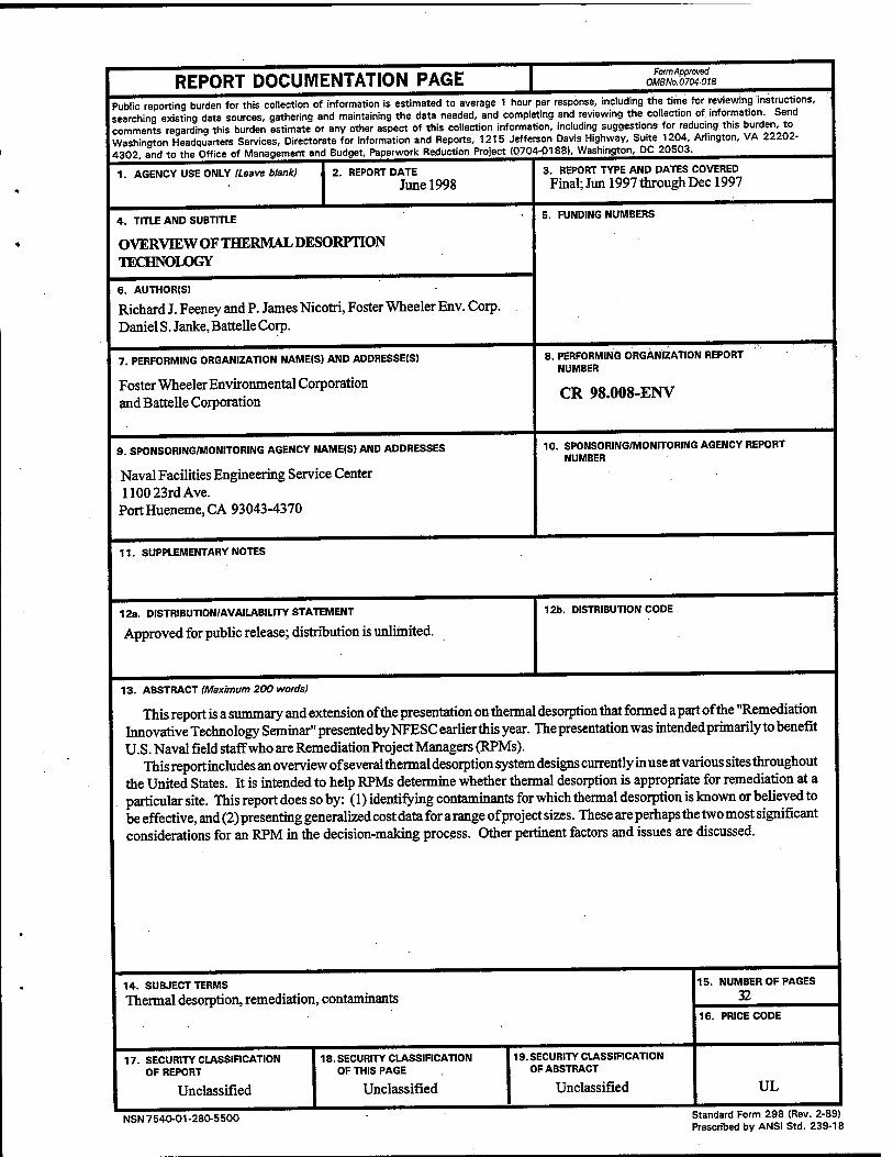
This report is a summary and extension of the presentation on thermal desorption that formed a part of the "Remediation Innovative Technology Seminar" presentedbyNFESCearlierthis year. The presentation was intended primarily to benefit U.S. Naval field staff who are Remediation Project Managers (RPMs).
This report includes an overview of several thermal desorption system designs currently in use at various sites throughout the United States. It is intended to help RPMs determine whether thermal desorption is appropriate for remediation at a particular site. This report does so by: (l)identifymgcontaminantsforwhichthermaldesorptionisknownorbelievedto be effective, and (2) presenting generalized cost data for a range of project sizes. These are perhaps the two most significant considerations for an RPM in the decision-making process. Other pertinent factors and issues are discussed.
14. SUBJECT TERMS
Thermal desorption, remediation, contaminants
17. SECURITY CLASSIFICATION OF REPORT
Unclassified
18.SECURITY CLASSIFICATION OF THIS PAGE
Unclassified
INSECURITY CLASSIFICATION OF ABSTRACT
Unclassified
15. NUMBER OF PAGES
32 16. PRICE CODE
UL
NSN 7540-01-280-5500 Standard Form 298 (Rev. 2-89) Prescribed by ANSI Std. 239-18
CONTENTS
FIGURES iü TABLES iv ACRONYMS AND ABBREVIATIONS »v ABSTRACT vi
Section 1.0: INTRODUCTION 1
Section 2.0: DEFINITION OF THERMAL DESORPTION 2 2.1 Technological Description of Thermal Desorption 2 2.2 Regulatory Perspective of Thermal Desorption 3
Section 3.0: APPLICABILITY OF THERMAL DESORPTION SYSTEMS 6
Section 4.0: OVERVIEW OF VARIOUS TYPES OF THERMAL DESORPTION SYSTEMS 10
4.1 Continuous-Feed Systems — Direct Contact 10 4.2 Continuous-Feed Systems — Indirect Contact 12 4.3 Batch-Feed Systems—Heated Oven 14 4.4 Batch-Feed Systems — HAVE System 16 4.5 Batch-Feed Systems — In Situ Systems: Thermal Blanket and Thermal Well 17 4.6 Batch-Feed Systems—In Situ Systems: Enhanced Soil Vapor Extraction 18
Section 5.0: DESIGN AND PERFORMANCE CHARACTERISTICS .19
Section 6.0: COST INFORMATION 22 6.1 Thermal Desorption Cost Information 22 6.2 Thermal Desorption Cost Compared to Costs for Alternative Technologies 24
Section 7.0: SUMMARY 25
Section 8.0: REFERENCES 26
FIGURES
Figure 1. Generic Thermal Desorption Process 2 Figure 2. Thermal Desorption Technology Selection Decision Tree 8 Figure 3. First Generation—Direct-Contact Thermal Desorption Process 11 Figure 4. Second Generation—Direct-Contact Thermal Desorption Process 11 Figure 5. Third Generation—Direct-Contact Thermal Desorption Process 12 Figure 6. Indirect-Contact Rotary Dryer Thermal Desorption Process 13 Figure 7. Typical Indirect-Contact Thermal Screw Thermal Desorption Process 14 Figure 8. Batch-Feed Thermal Desorption System—Indirect-Contact Heated Oven 15 Figure 9. Batch-Feed Thermal Desorption System—Direct-Contact HAVE System 16
iii
TABLES
Table 1. Effectiveness of Thermal Desorption on General Contaminant Groups for Soil, Sludge, Sediments, and Filter Cakes 6
Table 2. Typical Cost Information from Recent Literature 23 Table 3. Cost Comparison Data for Different Project Sizes 23 Table 4. Thermal Desorption Compared to Alternative Technologies 24
IV
ACRONYMS AND ABBREVIATIONS
BADCAT Bay Area Defense Conversion Action Team BCDP base-catalyzed decomposition process BTEX benzene, toluene, ethylbenzene, and xylenes
CEM continuous emissions monitoring CERCLA Comprehensive Environmental Response, Compensation, and Liability Act CY cubic yards
RCRA Resource Conservation and Recovery Act RFP request for proposals RITS Remediation Innovative Technology Seminar RPM Remediation Project Manager
SVE soil vapor extraction SVOC semivolatile organic compound
TD thermal desorption/desorber TPH total petroleum hydrocarbon TR technical report
VOC volatile organic compound
Section 1.0: INTRODUCTION
During mid-July and mid-August 1997, the Naval Facilities Engineering Service Center (NFESC) conducted a series of 1-day environmental technology seminars for personnel from Naval installations.
The program was entitled the "Remediation Innovative Technology Seminar" (RITS), and its purpose was to provide various Navy and Naval contractor personnel with an overview and description of the current status of several remedial technologies. One of the technologies described was thermal desorption. Information was compiled from a practical and applied standpoint, to familiarize Remediation Project Managers (RPMs) and other field personnel with the thermal desorption technology. The scope of the program did not include coverage of thermal treatment theory and detailed design parameters.
Presentation materials for this segment of the RITS were developed by Foster Wheeler Environmental Corporation (FWENC) through a subcontract with Battelle Memorial Institute, the prime contractor to NFESC. FWENC staff conducted the thermal desorption segment at the RITS.
This paper is intended to be a concise, narrative discussion of the salient points of the thermal desorption presentation. Further details are contained in the hard copy of the presenta- tion slides, distributed to each of the attendees in the form of the RITS course manual. Addi- tional copies of the manual are available through NFESC. An application guide for the thermal desorption technology is being developed and will include further information on implementing this technology. This document will be available from NFESC at Port Hueneme, California.
Section 2.0: DEFINITION OF THERMAL DESORPTION
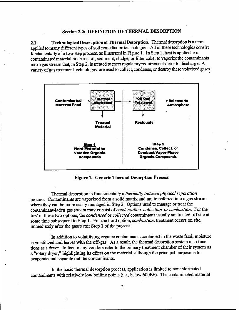
2.1 Technological Description of Thermal Desorption. Thermal desorption is a term applied to many different types of soil remediation technologies. All of these technologies consist fundamentally of a two-step process, as illustrated in Figure 1. In Step 1, heat is applied to a contaminated material, such as soil, sediment, sludge, or filter cake, to vaporize the contaminants into a gas stream that, in Step 2, is treated to meet regulatory requirements prior to discharge. A variety of gas treatment technologies are used to collect, condense, or destroy these volatized gases.
Contaminated —> Material Feed
Thermal Desorption
Off-Gas Treatment
Atmosphere
I I Treated Material
Residuals
Stepl Heat Material to Volatize Organic
Compounds
Step 2 Condense, Collect, or Combust Vapor-Phase Organic Compounds
Figure 1. Generic Thermal Desorption Process
Thermal desorption is fundamentally a thermally induced physical separation process. Contaminants are vaporized from a solid matrix and are transferred into a gas stream where they can be more easily managed in Step 2. Options used to manage or treat the contaminant-laden gas stream may consist of condensation, collection, or combustion. For the first of these two options, the condensed or collected contaminants usually are treated off site at some time subsequent to Step 1. For the third option, combustion, treatment occurs on site, immediately after the gases exit Step 1 of the process.
In addition to volatilizing organic contaminants contained in the waste feed, moisture is volatilized and leaves with the off-gas. As a result, the thermal desorption system also func- tions as a dryer. In fact, many vendors refer to the primary treatment chamber of their system as a "rotary dryer," highlighting its effect on the material, although the principal purpose is to evaporate and separate out the contaminants.
In the basic thermal desorption process, application is limited to nonchlorinated contaminants with relatively low boiling points (i.e., below 600EF). The contaminated material
typically is heated to between 300°F and 600°F, and the process is sometimes referred to as "low-temperature thermal desorption" (LTTD). Thermal desorption was eventually applied to contaminants having boiling points higher than 600°F. As a result, these systems have evolved so they are able to heat materials to temperatures in the range of 600°F to 1,200°F. In this case, the system is sometimes called "high-temperature thermal desorption" (HTTD). In either case, the treated material essentially retains its physical properties, although they may be modified somewhat when heated to higher temperatures. Thermal desorption technologies have not only been modified to treat high-boiling-point contaminants, but are also capable of treating a variety of chlorinated compounds.
Although these temperature ranges are typical for LTTD and HTTD systems (based on vendor information and past projects), there does not seem to be any clearly defined distinc- tion between LTTD and HTTD with regard to operating temperature. In fact, use of this termi- nology is not consistent in industry, with many HTTD systems referred to as LTTD systems. Sometimes the name given to the process or technology varies. On a project in New York State, the remedial technology selected in the Record of Decision and used in the remedial design was "low-temperature enhanced volatilization" (LTEV), which was essentially a thermal desorption process under a different name. As a consequence of these inconsistencies, the terms LTTD and HTTD will not be used further in this document.
2.2 Regulatory Perspective of Thermal Desorption. Although there is no "official" U.S. Environmental Protection Agency (EPA) definition of thermal desorption, one can be developed from several documents that have been either published by the EPA or derived from EPA-sponsored workshops on the technology.
According to the EPA Engineering Bulletin: Thermal Desorption Treatment (EPA/540/2-91/008, May 1991):
Thermal desorption is an ex situ means to physically separate volatile and some semivolatile contaminants from soil, sediments, sludges, and filter cakes.... Thermal desorption is applicable to organic wastes and generally is not used for treating metals and other inorganics. Depending on the specific thermal desorption vendor selected, the technology heats contaminated media between 200-1,000EF, driving off water and volatile contaminants. Off-gases may be burned in an afterburner, condensed to reduce the volume to be disposed, or captured by carbon adsorption beds.
On June 3 and 4,1991, Science Applications International Corporation in Cincinnati, Ohio conducted an EPA workshop on thermal desorption. The workshop was attended by repre- sentatives from the EPA, remediation contractors, academic institutions, and industry. The definition that emerged from that workshop was as follows:
Thermal desorption is an ex situ process that uses either direct or indirect heat exchange to vaporize and/or volatize contaminants from soil or sludge.... Thermal desorption systems are physical separation processes and are not designed to provide high levels of organic destruction.... Thermal desorption
is not incineration, because the decomposition of organic materials is not the desired result, although some decomposition may occur (SAIC, 1991).
Therefore, the EPA currently defines thermal desorption as a physical separation process, not as a form of incineration. However, some states may define certain types of thermal desorption systems as incinerators and require compliance with Resource Conservation and Recovery Act (RCRA) regulations. This illustrates the controversy surrounding some types of thermal desorption systems. By defining the technology as thermal desorption, permitting requirements are not as severe and public opposition usually is significantly lower. Conse- quently, more contaminated sites are being remediated. If the technology is classified as incin- eration, permitting becomes more difficult, operation becomes more expensive, and local public opposition becomes more of an obstacle. The result is that projects are delayed and sometimes even canceled, resulting in delays in cleaning up those sites. In summary, the definition of thermal desorption is currently controversial and continues to evolve.
On one hand, an attempt is being made in the industry to distinguish thermal desorp- tion from incineration. Regulatory authorities, contractors, and vendors recognize that by doing so they can, in many cases, avoid the public controversy and delays that inevitably arise concern- ing incineration projects. They also understand that, in many instances where thermal treatment is the preferred remedial technology, incineration, as fully defined in the regulations, is unneces- sary and is excessively expensive. Many of the remediation problems faced by the Navy involve benzene, toluene, ethylbenzene, and xylenes (BTEX) or total petroleum hydrocarbon (TPH)- contaminated soils. These problems are easily and successfully treated using proven thermal desorption technologies. High-temperature incineration would be more costly and usually is not needed, based on the physical and chemical characteristics of these contaminants.
On the other hand, some regulators feel the distinction between thermal desorption and incineration is unclear and enables shrewd contractors and vendors to avoid complying with incineration requirements in cases where they should be imposed. They are concerned that the potential for harm being caused to the public or the environment may be increased. As a result, the definition of thermal desorption is subject to interpretation and is applied inconsistently from project to project and state to state. The enforcement of RCRA regulations (which govern incin- eration performance), and sometimes Comprehensive Environmental Response, Compensation, and Liability Act (CERCLA) regulations (which govern site remediation activities), is largely delegated to the particular state agency where a project is located. Note that the definition's own language states mat "Volatiles in the off-gas may be burned in an afterburner...," which some technical people and state regulatory officials construe as incineration. Examples exist of the very same thermal equipment being used in an incineration application on one project and in a thermal desorption application on another project, with the only difference being the operating conditions used.
While thermal desorption is a proven technology recognized by the EPA for more than 10 years, the more recent use of higher thermal desorption operating temperatures has contributed to blurring the distinction between thermal desorption and incineration. The higher operating temperature implies that the separation process (of contaminants from the contami- nated media) occurs at a more elevated temperature. Because of this, and because of physical
equipment and material limitations, higher operating temperatures usually involve direct-contact modes of heat transfer (usually in a rotary dryer) and combustion of the off-gases in an after- burner. The resulting system looks very similar to an incinerator. Thus, the distinction between thermal desorption at high operating temperatures and incineration is very narrow.
Regardless of the nomenclature employed to describe the technology, RPMs must come to agreement with concerned regulators (normally the state environmental agency) early in a project to establish which regulations will apply when thermal treatment of any kind is to be used.
Section 3.0: APPLICABILITY OF THERMAL DESORPTION SYSTEMS
In general, thermal desorption is capable of treating various materials, including soil, sediment, sludge, and filter cake, contaminated with a wide range of organic contaminants. Petroleum, volatile organic compounds (VOCs), semivolatile organic compounds (SVOCs), pesticides, and other compounds with boiling points up to about 600°F are typically processed through direct- or indirect-contact thermal desorption units. Contaminants with boiling points above 600°F, such as polychlorinated biphenyls (PCBs), dioxins, and furans, may be treatable with higher-temperature systems. Thermal desorption is not thought to be effective for the treatment of organic corrosives and reactive oxidizers and reducers. More specific guidance on the effectiveness of thermal desorption for various specific contaminants is presented in Table 1.
Table 1. Effectiveness of Thermal Desorption on General Contaminant Groups for Soil, Sludge, Sediments, and Filter Cakes
Key: 1 - Demonstrated Effectiveness: Successful treatability at some scale completed. 2 - Potential Effectiveness: Expert opinion that the technology will work. 3 - No Expected Effectiveness: Expert opinion that the technology will not work.
Source: U.S. EPA, 1991, EPA/540/2-91/008.
In addition, according to the EPA, "The (thermal desorption) process is applicable for the separation of organics from refinery wastes, coal tar wastes, wood-treating wastes, creosote- contaminated soils, hydrocarbon-contaminated soils, mixed (radioactive and hazardous) wastes, synthetic rubber processing wastes and paint wastes" (U.S. EPA, 1991, EPA/540/2-91/008). Thermal desorption has been demonstrated to be effective for remediation of pesticide- contaminated soils and sediments and those from manufactured gas plants.
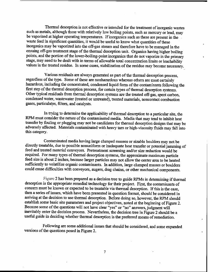
Thermal desorption is not effective or intended for the treatment of inorganic wastes such as metals, although those with relatively low boiling points, such as mercury or lead, may be vaporized at higher operating temperatures. If inorganics such as these are present in the waste feed in significant quantities, it would be useful to know what quantities of these inorganics may be vaporized into the off-gas stream and therefore have to be managed in the ensuing off-gas treatment stage of the thermal desorption unit. Organics having higher boiling points, and the portion of the lower-boiling-point inorganics that do not vaporize in the primary stage, may need to be dealt with in terms of allowable total concentration limits or leachability values in the treated residue. In some cases, stabilization of the residue may become necessary.
Various residuals are always generated as part of the thermal desorption process, regardless of the type. Some of these are nonhazardous whereas others are most certainly hazardous, including the concentrated, condensed liquid form of the contaminants following the first step of the thermal desorption process, for certain types of thermal desorption systems. Other typical residuals from thermal desorption systems are the treated off-gas, spent carbon, condensed water, wastewater (treated or untreated), treated materials, noncontact combustion gases, particulates, filters, and catalysts.
In trying to determine the applicability of thermal desorption to a particular site, the RPM must consider the nature of the contaminated media. Media that may tend to inhibit heat transfer by fouling or plugging may not be candidates for thermal desorption designs that may be adversely affected. Materials contaminated with heavy tars or high-viscosity fluids may fall into this category.
Contaminated media having large clumped masses or sizable boulders may not be directly treatable, due to possible nonuniform or inadequate heat transfer or potential jamming of feed and treated material conveyors. Pretreatment screening and/or size reduction would be required. For many types of thermal desorption systems, the approximate maximum particle feed size is about 2 inches, because larger particles may not allow the center area to be heated sufficiently to volatilize organic contaminants. In addition, large clumped masses or boulders could cause difficulties with conveyors, augers, drag chains, or other mechanical components.
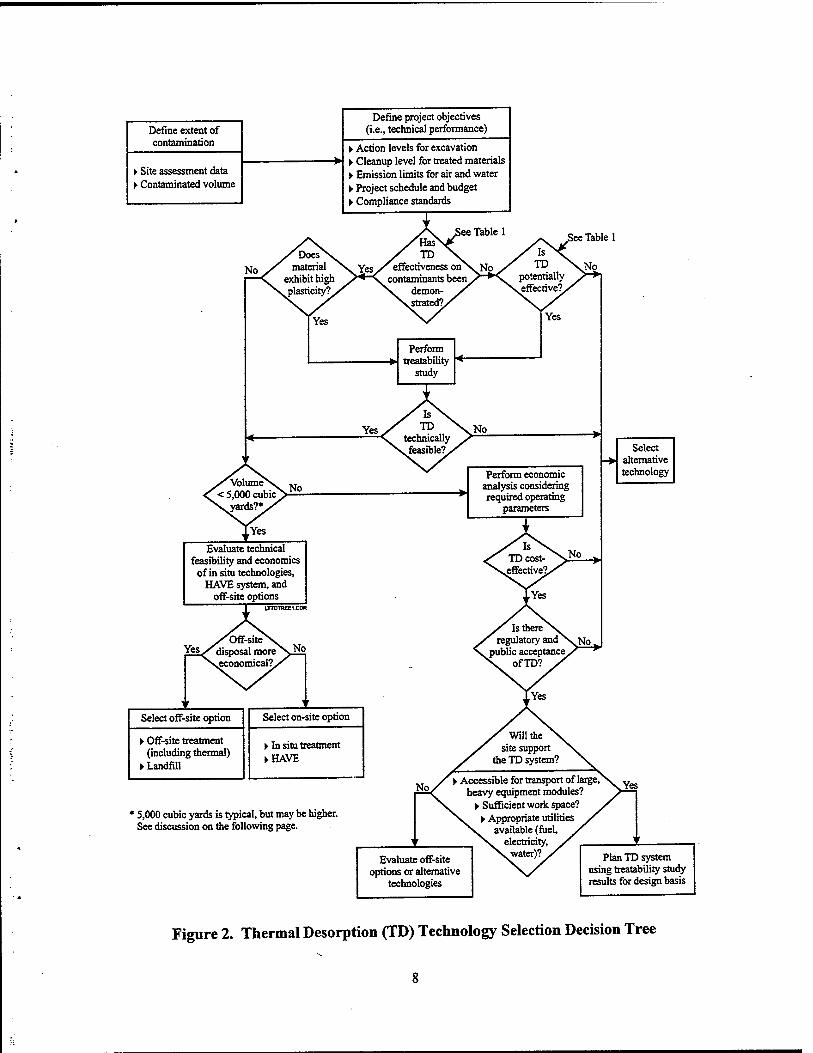
Figure 2 has been prepared as a decision tree to guide RPMs in determining if thermal desorption is the appropriate remedial technology for their project. First, the contaminants of concern must be known or expected to be treatable via thermal desorption. If this is the case, then a series of issues, which have been presented in question format, should be considered in arriving at the decision to use thermal desorption. Before doing so, however, the RPM should establish some basic site parameters and project objectives, noted at the beginning of Figure 2. Because some of the questions will not have clear "yes" or "no" answers, judgment will inevitably enter the decision process. Nevertheless, the decision tree in Figure 2 should be a useful guide in deciding whether thermal desorption is the preferred means of remediation.
Following are some additional issues that should be considered, and some expanded versions of the questions posed in Figure 2.
Define project objectives (i.e., technical performance) Define extent of
contamination ► Action levels for excavation y Cleanup level for treated materials ► Emission limits for air and water ► Project schedule and budget ► Compliance standards
Evaluate technical feasibility and economics of in situ technologies,
HAVE system, and off-site options
LTTOTREE1.CW
1
^MDff-siteN. fes/disposal more\2^
>yeconomicalT/
' Select off-site option Select on-site option
► Off-site treatment (including thermal)
► Landfill
► In situ treatment ► HAVE
Select alternative technology
* 5,000 cubic yards is typical, but may be higher. See discussion on the following page.
Evaluate off-site options or alternative
technologies
Plan TD system using treatability study results for design basis
Figure 2. Thermal Desorption (TD) Technology Selection Decision Tree
•
•
•
Are the concentrations of any inorganics or residual organics low enough that the treated materials can be disposed of readily by backfill, or perhaps with a low-priced subsequent treatment step such as stabilization?
Is there a time constraint? If yes, a large-scale thermal desorption unit could be used (although perhaps not cost-effectively) to quickly conduct a project, because relatively high treatment rates are achievable compared to other potentially useful technologies.
Is public acceptance of a thermal treatment process a concern, and is the local public likely to tolerate the deployment of a thermal desorption unit to the project site?
Are appropriate utilities available at the site (gas/liquefied petroleum gas [LPG]/fuel oil, electricity, water, etc.) in adequate supply?
Is sufficient space available at the project for the thermal desorption system, a waste feed preparation area, a treated residue staging area, and a water treatment system (if applicable)?
Will the cognizant regulatory agencies accept thermal desorption as a viable means of remediation, as differentiated from incineration?
Does the cost of thermal desorption, based on typical rates for comparable size projects, seem acceptable?
The 5,000-cubic-yard (CY) volume decision point for focusing on the use of in situ thermal desorption technologies, the HAVE system, and off-site options is a typical value. The actual volume of contaminated material at which these options are more economical is site-specific and depends on many factors, such as local labor costs, proximity of the project to off-site disposal facilities, regulatory agency acceptance of thermal desorption versus incineration, and so on. In some instances, the volume decision point may be as high as 10,000 CY.
Section 4.0: OVERVIEW OF VARIOUS TYPES OF THERMAL DESORPTION SYSTEMS
Today, a variety of thermal desorption systems are used as part of numerous government and private remediation projects. As stated earlier, all thermal desorption technologies consist of two steps: (1) heating the contaminated material to volatize the organic contaminants, and (2) treat- ing the exhaust gas stream to prevent emissions of the volatized contaminants to the atmosphere. The systems are differentiated from each other by the methods used to transfer heat to the contami- nated materials, and by the gas treatment system used to treat the off-gases. Heat can be applied directly by radiation from a combustion flame and/or by convection from direct contact with the combustion gases. Systems employing this type of heat transfer are referred to as direct-contact or direct-firedthermal desorption systems. Heat can also be applied indirectly by transferring the heat from the source (e.g., combustion or hot oil) through a physical barrier that separates the heat source from the contaminated materials, such as a steel wall. Systems employing this type of heat transfer are referred to as indirect-contact or indirect-fired'thermal desorption systems.
Thermal desorption systems can be further divided into two broad categories: continuous-feed and batch-feed types. Continuous-feed systems are ex situ processes, meaning that the contaminated material must be excavated from its original location, followed by some degree of material handling, and then fed to the treatment unit. Continuous-feed thermal desorp- tion systems can use direct-contact (direct-fired) equipment or indirect-contact (indirect-fired) equipment, as described previously. The following are representative types of continuous-feed thermal desorption technologies:
Batch-feed systems can be either ex situ or in situ, the latter meaning that the material is treated in place, without the need for and expense of excavating or dredging it before treat- ment. As with all thermal desorption systems, the off-gases from in situ systems must be treated prior to discharge to the atmosphere. The following are representative types of batch-feed thermal desorption technologies:
• Ex situ—heated oven and hot-air vapor extraction (HAVE) • In situ—thermal blanket, thermal well, "enhanced" soil vapor extraction.
4.1 Continuous-Feed Systems — Direct Contact. Direct-contact thermal desorption systems have been developed in at least three stages over the years. Throughputs of as high as 160 tons/hr have been demonstrated.
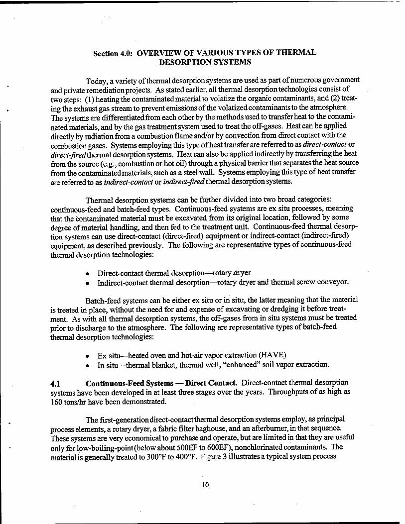
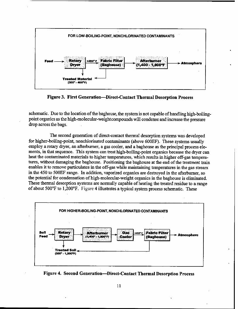
The first-generation direct-contact thermal desorption systems employ, as principal process elements, a rotary dryer, a fabric filter baghouse, and an afterburner, in that sequence. These systems are very economical to purchase and operate, but are limited in that they are useful only for low-boiling-point (below about 500EF to 600EF), nonchlorinated contaminants. The material is generally treated to 300°F to 400°F. Figure 3 illustrates a typical system process
10
FOR LOW-BOILING-POINT, NONCHLORINATED CONTAMINANTS
Feed Rotary Dryer
<450>F Fabric Filter (Baghouse)
Afterburner (1,400 - 1,800°F -»■ Atmosphere
Treated Material "*~ (300°-400°F)
Figure 3. First Generation—Direct-Contact Thermal Desorption Process
schematic. Due to the location of the baghouse, the system is not capable of handling high-boiling- point organics as the high-molecular-weightcompounds will condense and increase the pressure drop across the bags.
The second generation of direct-contact thermal desorption systems was developed for higher-boiling-point, nonchlorinated contaminants (above 600EF). These systems usually employ a rotary dryer, an afterburner, a gas cooler, and a baghouse as the principal process ele- ments, in that sequence. This system can treat high-boiling-point organics because the dryer can heat the contaminated materials to higher temperatures, which results in higher off-gas tempera- tures, without damaging the baghouse. Positioning the baghouse at the end of the treatment train enables it to remove particulates in the off-gas while maintaining temperatures in the gas stream in the 450 to 500EF range. In addition, vaporized organics are destroyed in the afterburner, so the potential for condensation of high-molecular-weight organics in the baghouse is eliminated. These thermal desorption systems are normally capable of heating the treated residue to a range of about 500°F to l,200°F. Figure 4 illustrates a typical system process schematic. These
FOR HIGHER-BOILING-POINT, NONCHLORINATED CONTAMINANTS
Soil Feed'
Rotary Dryer
Afterburner (1,400°-liMCF)
—> Gas Cooler
<4SVT Fabric Filter (Baghouse)
i Treated So (500° -1,200°
•I < F)
- Atmosphere
Figure 4. Second Generation—Direct-Contact Thermal Desorption Process
11
systems are now capable of treating materials contaminated with heavier oils, but are still limited to nonchlorinated compounds because they have no means of controlling the hydrochloric acid emissions resulting from the combustion of chlorinated compounds.
The third generation of direct-contact thermal desorption systems is intended for the treatment of high-boiling-point, chlorinated contaminants. Materials are usually heated to a range between 500°F and 1,200°F in a rotary dryer and the off-gas is subsequently oxidized in an afterburner at temperatures in the range of 1,400°F to 1,800°F, sometimes as high as 2,000°F. The off-gas is then cooled, or quenched, and passes through the baghouse as in a second-generation system. At the end of the treatment train, however, an acid gas neutralization system is included to control emissions of hydrochloric acid (HC1) to the atmosphere. A wet gas scrubber utilizing caustic-enriched water sprays is the most common acid gas control system used. Because the scrubber may be made of fiberglass^reinforced plastic (FRP) with a relatively low permissible operating temperature, an upstream quench stage (i.e., downstream of the baghouse) is typically used to cool the gas stream prior to entering the scrubber. The addition of a wet gas scrubber adds a significant degree of complexity to the thermal desorption system and the project because it involves water make-up, wastewater discharge flows, and monitoring and control of water chem- istry. In addition, some degree of particulate collection is achieved by the wet scrubber system. This particulate becomes sludge in the wastewater treatment system and must be removed and managed prior to discharge.
Figure 5 illustrates a typical system process schematic. Note that this third- generation system is capable of handling and treating a very wide range of potential contami- nants, including heavy oils and chlorinated compounds.
FOR HIGH-BOILING-POINT, CHLORINATED CONTAMINANTS
Feed
Rotaiy Dryer
—»■ Afterburner (1I400-1,800°F)
Gas Cooler
<450*E Fabric Filter (Baghouse)
Treated Material. (500-1,200°F)
Wet Scrubber
Atmosphere
T Wastewater Treatment
and Discharge
Figure 5. Third Generation—Direct-Contact Thermal Desorption Process
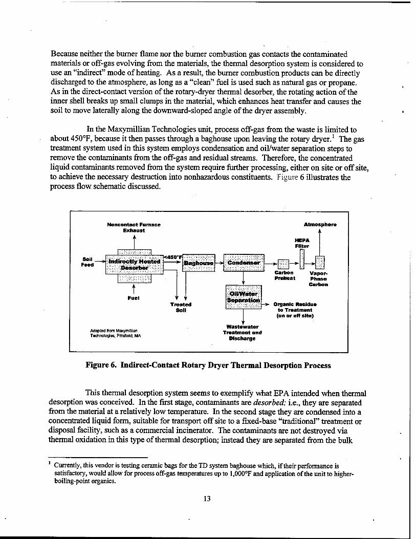
4.2 Continuous-Feed Systems — Indirect Contact. Indirect-contact thermal desorption systems come in many types of designs. One such system (owned by Maxymillian Technolo- gies) uses a double-shell rotary dryer, with several burners mounted in the annular space between the two shells. The burners heat the exterior of the inner shell containing the waste as it rotates.
12
Because neither the burner flame nor the burner combustion gas contacts the contaminated materials or off-gas evolving from the materials, the thermal desorption system is considered to use an "indirect" mode of heating. As a result, the burner combustion products can be directly discharged to the atmosphere, as long as a "clean" fuel is used such as natural gas or propane. As in the direct-contact version of the rotary-dryer thermal desorber, the rotating action of the inner shell breaks up small clumps in the material, which enhances heat transfer and causes the soil to move laterally along the downward-sloped angle of the dryer assembly.
In the Maxymillian Technologies unit, process off-gas from the waste is limited to about 450°F, because it then passes through a baghouse upon leaving the rotary dryer.1 The gas treatment system used in this system employs condensation and oil/water separation steps to remove the contaminants from the off-gas and residual streams. Therefore, the concentrated liquid contaminants removed from the system require further processing, either on site or off site, to achieve the necessary destruction into nonhazardous constituents. Figure 6 illustrates the process flow schematic discussed.
Noncontact Furnace Exhaust
Atmosphere
HEPA Filter
Soil . Feed Indirectly Heated
Desorber
<450*F —*■
Fuel
Adapted from Maxymillian Technologies, PWsfield, MA
Baghouse »: Condenser Carbon Preheat
Treated Soil
Oil/Water Separation
Vapor- Phase Carbon
Organic Residue to Treatment (on or off site)
Wastewater Treatment and
Discharge
Figure 6. Indirect-Contact Rotary Dryer Thermal Desorption Process
This thermal desorption system seems to exemplify what EPA intended when thermal desorption was conceived. In the first stage, contaminants are desorbed; i.e., they are separated from the material at a relatively low temperature. In the second stage they are condensed into a concentrated liquid form, suitable for transport off site to a fixed-base "traditional" treatment or disposal facility, such as a commercial incinerator. The contaminants are not destroyed via thermal oxidation in this type of thermal desorption; instead they are separated from the bulk
1 Currently, this vendor is testing ceramic bags for the TD system baghouse which, if their performance is satisfactory, would allow for process off-gas temperatures up to 1,000°F and application of the unit to higher- boiling-point organics.
13
material for subsequent processing elsewhere. This type of thermal desorption process reduces the volume of contaminants that require further treatment.
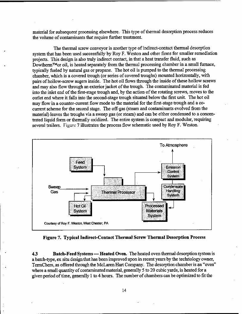
The thermal screw conveyor is another type of indirect-contact thermal desorption system that has been used successfully by Roy F. Weston and other firms for smaller remediation projects. This design is also truly indirect contact, in that a heat transfer fluid, such as Dowtherm™or oil, is heated separately from the thermal processing chamber in a small furnace, typically fueled by natural gas or propane. The hot oil is pumped to the thermal processing chamber, which is a covered trough (or series of covered troughs) mounted horizontally, with pairs of hollow-screw augers inside. The hot oil flows through the inside of these hollow screws and may also flow through an exterior jacket of the trough. The contaminated material is fed into the inlet end of the first-stage trough and, by the action of the rotating screws, moves to the outlet end where it falls into the second-stage trough situated below the first unit. The hot oil may flow in a counter-current flow mode to the material for the first-stage trough and a co- current scheme for the second stage. The off-gas (steam and contaminants evolved from the material) leaves the troughs via a sweep gas (or steam) and can be either condensed to a concen- trated liquid form or thermally oxidized. The entire system is compact and modular, requiring several trailers. Figure 7 illustrates the process flow schematic used by Roy F. Weston.
1 0/ ttm ospher e
Feed System Emission
Control System > '
1 1 , Sweep
Thermal Processor
Condensate Handling System
Gas
V '
Hot Oil System
Processed Materials System
■<-
Courtesy of Roy F .w eston, West Chester, PA
Figure 7. Typical Indirect-Contact Thermal Screw Thermal Desorption Process
43 Batch-Feed Systems — Heated Oven. The heated oven thermal desorption system is a batch-type, ex situ design that has been improved upon in recent years by the technology owner, TerraChem, as offered through the McLaren Hart Company. The desorption chamber is an "oven" where a small quantity of contaminated material, generally 5 to 20 cubic yards, is heated for a given period of time, generally 1 to 4 hours. The number of chambers can be optimized to fit the
14
project in terms of the total quantity of material to be treated, the timeframe to complete the project, the actual amount of time required per batch for the particular material and contaminant, the plot space available, and other variables. Normally, four or more chambers are utilized.
The heat source consists of aluminized steel tubes that are directly heated internally via propane to about 1,100°F. At this temperature, they emit infrared heat externally as they radiate, which the vendor claims is more efficient than other means of heat transfer. Although the radiant energy heats only the top several inches of the 18-inch-deep bed of contaminated material, a downward flow of air is drawn through the bed by an induced draft fan downstream of the treatment chamber. This creates a convective mode of heat transfer, which serves to strip the contaminants from the material. The treatment chamber itself operates at a negative pressure. This system is illustrated in Figure 8.
In recent years, the technology licensor has sought to adapt the system equipment to Wgher-boilmg-pomtcontaminants, such as PCBs, by modifying the design to maintain higher levels of vacuum. In doing so, the boiling point temperature of the contaminated media is effectively reduced, because the operating pressure is maintained significantly below atmospheric pressure. A related improvement pertains to the seals for the treatment chamber. The original design employed a sliding cover that was moved laterally to allow access for loading and unloading of the contami- nated material by a front-end loader. The newer, higher-vacuum model has a smaller access door that is easier to seal more effectively, and the waste material is loaded and unloaded through a side door using a tray handled by a forklift. Although the heated-oven system has advantages in terms of simplicity, plot space, and setup time required, it is lessiibiquitous than some alternative thermal desorbers such as the rotary dryer, and it is best suited to smaller projects. Its throughput is rela- tively low and, because of the batch nature and small treatment chamber size, a significant amount of labor is expended in the loading and unloading processes.
15
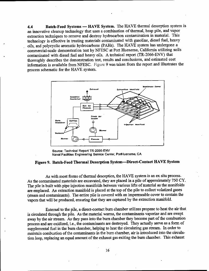
4.4 Batch-Feed Systems — HAVE System. The HAVE thermal desorption system is an innovative cleanup technology that uses a combination of thermal, heap pile, and vapor extraction techniques to remove and destroy hydrocarbon contamination in material. This technology is effective in treating materials contaminated with gasoline, diesel fuel, heavy oils, and polycyclic aromatic hydrocarbons (PAHs). The HAVE system has undergone a commercial-scale demonstration test by NFESG at Port Hueneme, California utilizing soils contaminated with diesel fuel and heavy oils. A technical report (TR-2066-ENV) that thoroughly describes the demonstration test, results and conclusions, and estimated cost information is available from NFESC. Figure 9 was taken from the report and illustrates the process schematic for the HAVE system.
Membrane Cover
t Extraction Manifold
Catalytic Converter
Burn Chamber
Hot Air Plenum
/ V
Fresh Air Intake
Burners
Blower ̂T 9
Infection Manifold
Source: Technical Report TR-2066-ENV Naval Facilities Engineering Service Center, PorHueneme, CA
Figure 9. Batch-Feed Thermal Desorption System—Direct-Contact HAVE System
As with most forms of thermal desorption, the HAVE system is an ex situ process. As the contaminated materials are excavated, they are placed in a pile of approximately 750 CY. The pile is built with pipe injection manifolds between various lifts of material as the manifolds are emplaced. An extraction manifold is placed at the top of the pile to collect volatized gases (steam and contaminants). The entire pile is covered with an impermeable cover to contain the vapors that will be produced, ensuring that they are captured by the extraction manifold.
External to the pile, a direct-contact burn chamber utilizes propane to heat the air that is circulated through the pile. As the material warms, the contaminants vaporize and are swept away by the air stream. As they pass into the burn chamber they become part of the combustion process and are oxidized, i.e., the contaminants are destroyed. They actually serve as a form of supplemental fuel in the burn chamber, helping to heat the circulating gas stream. In order to maintain combustion of the contaminants in the burn chamber, air is introduced into the circula- tion loop, replacing an equal amount of the exhaust gas exiting the burn chamber. This exhaust
16
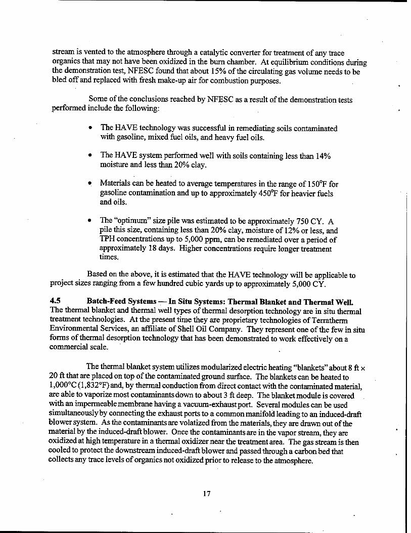
stream is vented to the atmosphere through a catalytic converter for treatment of any trace organics that may not have been oxidized in the burn chamber. At equilibrium conditions during the demonstration test, NFESC found that about 15% of the circulating gas volume needs to be bled off and replaced with fresh make-up air for combustion purposes.
Some of the conclusions reached by NFESC as a result of the demonstration tests performed include the following:
• The HAVE technology was successful in remediating soils contaminated with gasoline, mixed fuel oils, and heavy fuel oils.
• The HAVE system performed well with soils containing less than 14% moisture and less than 20% clay.
• Materials can be heated to average temperatures in the range of 150°F for gasoline contamination and up to approximately 450°F for heavier fuels and oils.
• The "optimum" size pile was estimated to be approximately 750 CY. A pile this size, containing less than 20% clay, moisture of 12% or less, and TPH concentrations up to 5,000 ppm, can be remediated over a period of approximately 18 days. Higher concentrations require longer treatment times.
Based on the above, it is estimated that the HAVE technology will be applicable to project sizes ranging from a few hundred cubic yards up to approximately 5,000 CY.
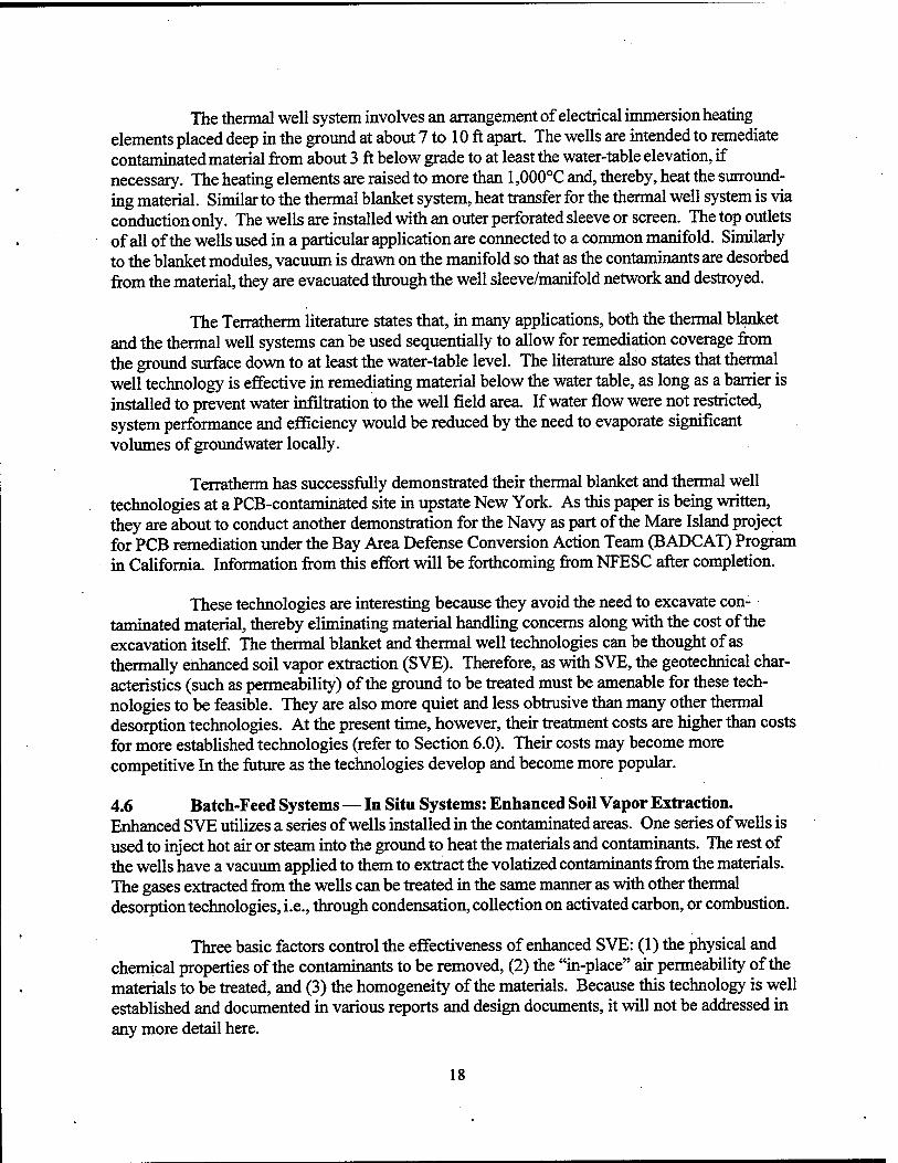
4.5 Batch-Feed Systems — In Situ Systems: Thermal Blanket and Thermal Well. The thermal blanket and thermal well types of thermal desorption technology are in situ thermal treatment technologies. At the present time they are proprietary technologies of Terratherm Environmental Services, an affiliate of Shell Oil Company. They represent one of the few in situ forms of thermal desorption technology that has been demonstrated to work effectively on a commercial scale.
The thermal blanket system utilizes modularized electric heating "blankets" about 8 ft x 20 ft that are placed on top of the contaminated ground surface. The blankets can be heated to 1,000°C (1,832°F) and, by thermal conduction from direct contact with the contaminated material, are able to vaporize most contaminants down to about 3 ft deep. The blanket module is covered with an impermeable membrane having a vacuum-exhaust port. Several modules can be used simultaneously by connecting the exhaust ports to a common manifold leading to an induced-draft blower system. As the contaminants are volatized from the materials, they are drawn out of the material by the induced-draft blower. Once the contaminants are in the vapor stream, they are oxidized at high temperature in a thermal oxidizer near the treatment area. The gas stream is then cooled to protect the downstream induced-draft blower and passed through a carbon bed that collects any trace levels of organics not oxidized prior to release to the atmosphere.
17
The thermal well system involves an arrangement of electrical immersion heating elements placed deep in the ground at about 7 to 10 ft apart. The wells are intended to remediate contaminated material from about 3 ft below grade to at least the water-table elevation, if necessary. The heating elements are raised to more than 1,000°C and, thereby, heat the surround- ing material. Similar to the thermal blanket system, heat transfer for the thermal well system is via conduction only. The wells are installed with an outer perforated sleeve or screen. The top outlets of all of the wells used in a particular application are connected to a common manifold. Similarly to the blanket modules, vacuum is drawn on the manifold so that as the contaminants are desorbed from the material, they are evacuated through the well sleeve/manifold network and destroyed.
The Terratherm literature states that, in many applications, both the thermal blanket and the thermal well systems can be used sequentially to allow for remediation coverage from the ground surface down to at least the water-table level. The literature also states that thermal well technology is effective in remediating material below the water table, as long as a barrier is installed to prevent water infiltration to the well field area. If water flow were not restricted, system performance and efficiency would be reduced by the need to evaporate significant volumes of groundwater locally.
Terratherm has successfully demonstrated their thermal blanket and thermal well technologies at a PCB-contaminated site in upstate New York. As this paper is being written, they are about to conduct another demonstration for the Navy as part of the Mare Island project for PCB remediation under the Bay Area Defense Conversion Action Team (B ADC AT) Program in California. Information from this effort will be forthcoming from NFESC after completion.
These technologies are interesting because they avoid the need to excavate con- taminated material, thereby eliminating material handling concerns along with the cost of the excavation itself. The thermal blanket and thermal well technologies can be thought of as thermally enhanced soil vapor extraction (SVE). Therefore, as with SVE, the geotechnical char- acteristics (such as permeability) of the ground to be treated must be amenable for these tech- nologies to be feasible. They are also more quiet and less obtrusive than many other thermal desorption technologies. At the present time, however, their treatment costs are higher than costs for more established technologies (refer to Section 6.0). Their costs may become more competitive In the future as the technologies develop and become more popular.
4.6 Batch-Feed Systems — In Situ Systems: Enhanced Soil Vapor Extraction. Enhanced SVE utilizes a series of wells installed in the contaminated areas. One series of wells is used to inject hot air or steam into the ground to heat the materials and contaminants. The rest of the wells have a vacuum applied to them to extract the volatized contaminants from the materials. The gases extracted from the wells can be treated in the same manner as with other thermal desorption technologies, i.e., through condensation, collection on activated carbon, or combustion.
Three basic factors control the effectiveness of enhanced SVE: (1) the physical and chemical properties of the contaminants to be removed, (2) the "in-place" air permeability of the materials to be treated, and (3) the homogeneity of the materials. Because this technology is well established and documented in various reports and design documents, it will not be addressed in any more detail here.
18
Section 5.0: DESIGN AND PERFORMANCE CHARACTERISTICS
The design and performance of a particular type of thermal desorption unit can usually be predicted reliably, as long as the nature of the contaminated media to be processed can be defined and is somewhat consistent. Most of the technologies have been in use for several years, often as outgrowths of other types of industry, so that equipment design parameters are well established. For example, one can readily determine the expected throughput for a rotary dryer based on the qualities and consistency of the waste to be fed. The waste feed preparation stage of the remediation process, therefore, is vitally important in predicting and ensuring the success of the subsequent thermal treatment step.
Because soils and sediments are inherently variable in their physical and chemical char- acteristics, the ability to accurately describe these characteristics is critical. Some of the important properties of the waste material, and the reasons for considering the properties, are as follows:
• Particle Size Distribution. This is one of several indicators of potential carryover of fines in rotary dryer systems, which can be problematic. The breakpoint between coarse-grained material and fine-grained material is generally defined by the percentage of particles greater or smaller than a No. 200 sieve (0.075 mm). Fine material consisting of silts and clays is likely to become "carried over" in a rotary-dryer system, meaning that it will exit the dryer entrained in the gas stream instead of with the treated residue, which is preferred. The undesirable carryover can overload the downstream gas-handling and treatment equipment, causing pressure profile and buildup problems, and possibly exceeding the ability of the baghouse or cyclone and conveyor equipment to recover it and rejoin the fines with the treated residue. In addition to particle size distribution, several other design or operating characteristics of the thermal desorption system influence particle carryover.
• Composition (Degree of Sand, Clay, Silt, Rock, etc.). For heat transfer and mechanical handling considerations, it is useful to review information on com- position. In general, coarse, unconsolidated materials, such as sands and fine gravels, are more readily treated by thermal desorption, because they tend not to agglomerate into larger particles. Hence, more of the surface area of the par- ticles is exposed to the heating medium. Agglomerated particles are somewhat self-insulating, which may interfere with thorough heat and mass transfer, and hence, desorption of the contaminants. A similar, undesirable phenomenon would occur with the processing of large rocks (in addition to material-handling difficulties for conveyors and augers). Consequently, the maximum particle size is typically limited to 2 inches for materials fed to rotary-dryer systems. Clays may cause poor thermal desorption performance because they tend to increase agglomeration and caking and thereby inhibit heat and mass transfer.
• Bulk Density. This property is of interest for ex situ processes, as a conversion between tons and C Y. For vendors to determine operating costs, the actual weight of the material to be treated is more important than the volume, in order to develop heat and mass balance relationships. However, volume tends to be
19
•
•
used as a basis for payment because it can be accurately measured in place by survey, without consideration of whether a weigh scale was calibrated properly or sufficiently, and without the need to subtract the weight of feed material that may have been reprocessed and hence crossed the feed scale twice.
Permeability. Knowledge of this property is particularly important for those processes (such as the HAVE system) involving the induction of vaporized contaminants through the material.
Plasticity. This property indicates the degree of material deformation without shearing. Plastic materials, such as clays, can clump and form larger particles with low surface area to volume ratios, possibly resulting in inadequate desorption in the interior core. They can also foul heat transfer surfaces, such as the exterior of a hot oil screw auger, decreasing thermal efficiency. Plastic materials may present material handling problems both before and during thermal desorption processing due to sticking and possibly jamming effects.
In-Place Homogeneity. This characteristic is important for in situ thermal desorption treatments, such as the thermal well and thermal blanket designs. Ideally, the subsurface should be quite homogeneous, so that the underground vapor flow, heat transfer, and remediation are uniform. Large boulders, bedrock irregularities, sand lenses, or impermeable layers (such as clay) might adversely affect the consistency of the treatment process.
Moisture Content The degree of moisture can adversely affect operating costs because moisture is evaporated in the treatment process, requiring fuel. More- over, the added volume of water vapor in the process off-gas can result in a lower waste throughput, because the water vapor must be handled by the downstream treatment equipment along with the balance of the off-gas and the desorbed contaminants. The lower processing throughput is attributable to (1) higher gas flows, resulting in greater pressure drops through the thermal desorption system; and (2) thermal input limitations (i.e., because some of the heating input is used to vaporize the water in the waste feed, it may become necessary to reduce the feed rate so that the waste which is fed can be heated adequately to achieve satisfactory desorption). For most rotary thermal desorp- tion systems, up to approximately 20% (by weight) moisture content can be present in the feed with no significant effect on operational cost and/or through- put. Beyond 20% moisture content, it may be desirable to investigate whether the moisture content could be lowered more economically in the waste feed preparation process rather than in the thermal treatment process itself.
On the other hand, it should also be pointed out that some thermal desorption systems perform more effectively with a certain minimum amount of moisture in the feed material. The HAVE system is one such example. This may be due to the enhanced heat transfer and thermal desorption of the contaminants resulting from the stripping action of the vaporized water (i.e., by steam).
20
Additionally, some minimum amount of moisture is desirable in the waste feed to mitigate dusting problems during material-handling operations.
In conclusion, between 10 and 20% (by weight) moisture content in the waste feed would be optimal in general.
• Heat Content. Some thermal desorption units are designed with a maximum thermal release that they can accommodate, including that from the waste feed material. For contaminated materials of low concentration; however, this is not usually a concern because a relatively small heat release in the thermal desorber is derived from the waste, and nearly all heat is obtained from combustion of the auxiliary fuel.
• Contaminant Type, Concentration, and Distribution. With this informa- tion, material excavation plans can be determined to allow for blending and some degree of "normalizing" of the waste to achieve a more consistent feed to the thermal desorber, enabling it to operate more predictably.
• Halogen Content. Consideration must be given relative to allowable emis- sion levels to determine whether acid gas neutralization equipment, such as a scrubber, will be required. One also needs to carefully consider the materials used for construction to minimize corrosion problems when the waste contains halogenated compounds.
• Metals Concentrations. Although it is difficult to predict the amount of metals that will be retained in the treated material versus how much will be carried over into the gas stream (perhaps eventually accumulating in the scrubber water), other regulatory issues may arise. For example, if the total or leachable concentrations exceed regulatory limits, backfilling may not be an option unless further treatment is performed.
• Alkali Salt Content. This property is used to anticipate whether fusing or "slagging" of the treated residue in rotary-dryer systems is likely, which could present material handling and other problems. It is also used to predict potential slagging problems in the afterburner, when utilized.
Considering all of the various thermal desorption technologies described above, one should recognize that performance varies by the type of unit, the site characteristics, and the particular contaminants. In general, however, all units can meet regulatory criteria although difficulty may arise in determining which regulatory criteria apply. Batch-type thermal desorp- tion systems generally require more processing time and hence are more suited to smaller projects. Direct-contact units generally are more efficient and are able to provide significantly lower (typically nondetectable) residual concentrations of contaminants.
More detailed information on typical relative design and performance characteristics for the various thermal desorption systems discussed is included in the Thermal Desorption Application Guide available from NFESC (TR-2090-ENV).
21
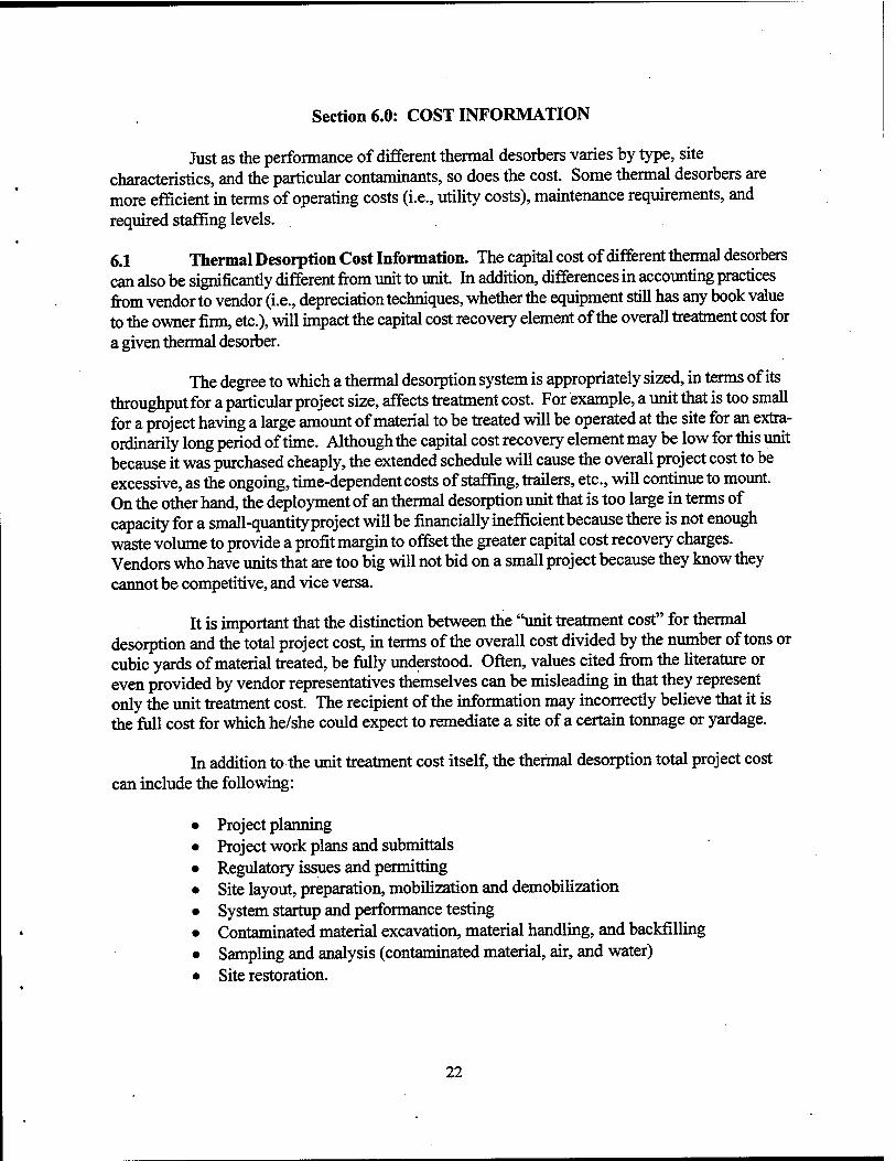
Section 6.0: COST INFORMATION
Just as the performance of different thermal desorbers varies by type, site characteristics, and the particular contaminants, so does the cost. Some thermal desorbers are more efficient in terms of operating costs (i.e., utility costs), maintenance requirements, and required staffing levels.
6.1 Thermal Desorption Cost Information. The capital cost of different thermal desorbers can also be significantly different from unit to unit. In addition, differences in accounting practices from vendor to vendor (i.e., depreciation techniques, whether the equipment still has any book value to the owner firm, etc.), will impact the capital cost recovery element of the overall treatment cost for a given thermal desorber.
The degree to which a thermal desorption system is appropriately sized, in terms of its throughput for a particular project size, affects treatment cost. For example, a unit that is too small for a project having a large amount of material to be treated will be operated at the site for an extra- ordinarily long period of time. Although the capital cost recovery element may be low for this unit because it was purchased cheaply, the extended schedule will cause the overall project cost to be excessive, as the ongoing, time-dependent costs of staffing, trailers, etc., will continue to mount. On the other hand, the deployment of an thermal desorption unit that is too large in terms of capacity for a small-quantity project will be financially inefficient because there is not enough waste volume to provide a profit margin to offset the greater capital cost recovery charges. Vendors who have units that are too big will not bid on a small project because they know they cannot be competitive, and vice versa.
It is important that the distinction between the "unit treatment cost" for thermal desorption and the total project cost, in terms of the overall cost divided by the number of tons or cubic yards of material treated, be fully understood. Often, values cited from the literature or even provided by vendor representatives themselves can be misleading in that they represent only the unit treatment cost. The recipient of the information may incorrectly believe that it is the full cost for which he/she could expect to remediate a site of a certain tonnage or yardage.
In addition to the unit treatment cost itself, the thermal desorption total project cost can include the following:
• Project planning • Project work plans and submittals • Regulatory issues and permitting • Site layout, preparation, mobilization and demobilization • System startup and performance testing • Contaminated material excavation, material handling, and backfilling • Sampling and analysis (contaminated material, air, and water) • Site restoration.
22
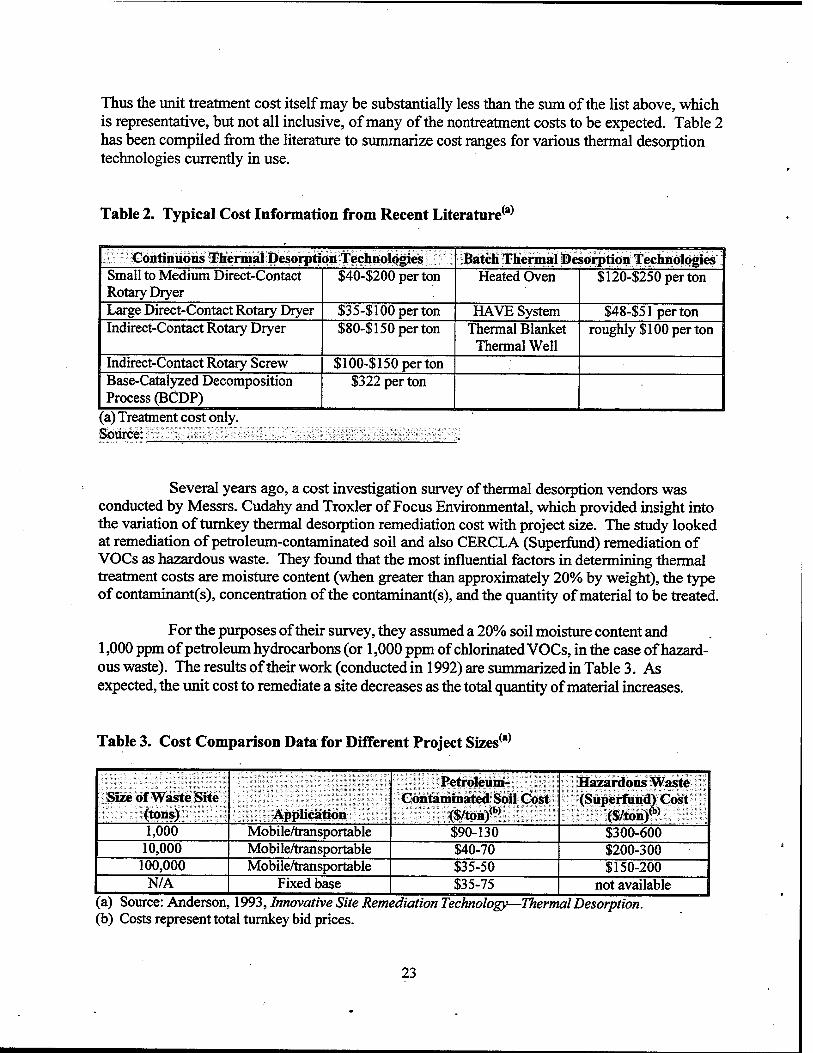
Thus the unit treatment cost itself may be substantially less than the sum of the list above, which is representative, but not all inclusive, of many of the nontreatment costs to be expected. Table 2 has been compiled from the literature to summarize cost ranges for various thermal desorption technologies currently in use.
Table 2. Typical Cost Information from Recent Literature(a)
Continuous Thermal Desorption Technologies Batch Thermal Desorption Technologies Small to Medium Direct-Contact Rotary Dryer
$40-$200perton Heated Oven $120-$250perton
Large Direct-Contact Rotary Dryer $3 5-$ 100 per ton HAVE System $48-$51perton Indirect-Contact Rotary Dryer $80-$ 150 per ton Thermal Blanket
Thermal Well roughly $100 per ton
Indirect-Contact Rotary Screw $100-$ 150 per ton Base-Catalyzed Decomposition Process (BCDP)
$322 per ton
(a) Treatment cost only. Source
Several years ago, a cost investigation survey of thermal desorption vendors was conducted by Messrs. Cudahy and Troxler of Focus Environmental, which provided insight into the variation of turnkey thermal desorption remediation cost with project size. The study looked at remediation of petroleum-contaminated soil and also CERCLA (Superfund) remediation of VOCs as hazardous waste. They found that the most influential factors in determining thermal treatment costs are moisture content (when greater than approximately 20% by weight), the type of contaminant(s), concentration of the contaminants), and the quantity of material to be treated.
For the purposes of their survey, they assumed a 20% soil moisture content and 1,000 ppm of petroleum hydrocarbons (or 1,000 ppm of chlorinated VOCs, in the case of hazard- ous waste). The results of their work (conducted in 1992) are summarized in Table 3. As expected, the unit cost to remediate a site decreases as the total quantity of material increases.
Table 3. Cost Comparison Data for Different Project Sizes(a)
100,000 Mobile/transportable $35-50 $150-200 N/A Fixed base $35-75 not available
(a) Source: Anderson, 1993, Innovative Site Remediation Technology—Thermal Desorption. (b) Costs represent total turnkey bid prices.
23
Also, the costs to remediate hazardous waste, such as at a Superfund site, are much higher than a simple cleanup of petroleum-contaminatedsoil. As a point of comparative reference, Cudahy and Troxler included pricing for the case of off-site treatment at a fixed-base thermal facility as an alternative to bringing a mobile thermal desorption system to the project site.
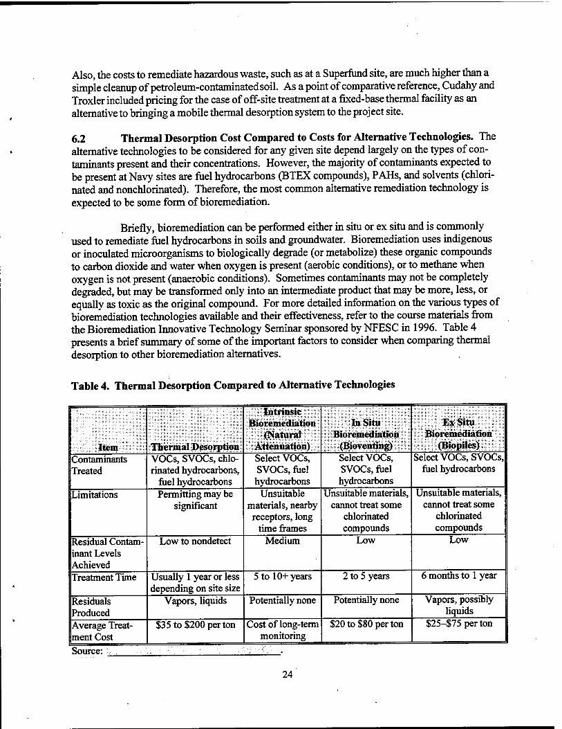
6.2 Thermal Desorption Cost Compared to Costs for Alternative Technologies. The alternative technologies to be considered for any given site depend largely on the types of con- taminants present and their concentrations. However, the majority of contaminants expected to be present at Navy sites are fuel hydrocarbons (BTEX compounds), PAHs, and solvents (chlori- nated and nonchlorinated). Therefore, the most common alternative remediation technology is expected to be some form of bioremediation.
Briefly, bioremediation can be performed either in situ or ex situ and is commonly used to remediate fuel hydrocarbons in soils and groundwater. Bioremediation uses indigenous or inoculated microorganisms to biologically degrade (or metabolize) these organic compounds to carbon dioxide and water when oxygen is present (aerobic conditions), or to methane when oxygen is not present (anaerobic conditions). Sometimes contaminants may not be completely degraded, but may be transformed only into an intermediate product that may be more, less, or equally as toxic as the original compound. For more detailed information on the various types of bioremediation technologies available and their effectiveness, refer to the course materials from the Bioremediation Innovative Technology Seminar sponsored by NFESC in 1996. Table 4 presents a brief summary of some of the important factors to consider when comparing thermal desorption to other bioremediation alternatives.
Table 4. Thermal Desorption Compared to Alternative Technologies
Item Thermal Desorption
Intrinsic Bioremediation
(Natural Attenuation)
In Situ Bioremediation
(Bioventing)
Ex Situ Bioremediation
(Biopiles) Contaminants Treated
VOCs, SVOCs, chlo- rinated hydrocarbons,
fuel hydrocarbons
Select VOCs, SVOCs, fuel hydrocarbons
Select VOCs, SVOCs, fuel hydrocarbons
Select VOCs, SVOCs, fuel hydrocarbons
Limitations Permitting may be significant
Unsuitable materials, nearby receptors, long
time frames
Unsuitable materials, cannot treat some
chlorinated compounds
Unsuitable materials, cannot treat some
chlorinated compounds
Residual Contam- inant Levels Achieved
Low to nondetect Medium Low Low
Treatment Time Usually 1 year or less depending on site size
There are a variety of thermal desorption systems available to suit almost any project. Among them are systems employing rotary dryers (both direct- and indirect-contact), thermal screw conveyors, heated ovens, and HAVE. In situ systems employing termal blankets and thermal wells are also available. Once the site and the contaminants have been characterized, the appropriate remediation approach and technology can be selected. Whether thermal desorption or some other technology is used will depend on site-specific criteria, such as the type of con- tamination, the site characteristics, regulatory agency acceptance, and the quantity of contaminated materials.
Once the determination has been made that thermal treatment is the appropriate remedy for a site, and the regulatory agencies have agreed that thermal desorption is acceptable, the competitive marketplace will determine the correct size, type, cost, and other considerations. Technical specifications for thermal treatment project solicitations are usually performance oriented rather than providing all of the detailed design information necessary to conduct the work. They generally describe the nature of the problem (how many cubic yards or tons of material to be treated, the contaminants of concern, other chemical and physical characteristics, etc.), the treatment standards to be achieved, and the timeframe allowed. The marketplace will then determine the most competitive technology for each site.
From this, experienced vendors/contractors will assess whether they have the correct equipment to do the work and if they are resourceful enough to perform the work efficiently. The details of their approach and technology will be described in their technical and cost pro- posals. The solicitor's task is then to determine which offeror provides the best value for his/her project overall, in terms of a balance between cost, technical approach, schedule, qualifications of key personnel, and past experience of the offeror's firm. Note that the expression "best value" has been used intentionally because selection of the lowest price bidder is not always the best alternative.
For more information on how these technologies are designed and on their costs, applicability to various projects, and how to implement them, please refer to the Thermal Desorption Application Guide, available from NFESC (TR-2090-ENV).
Thermal desorption can be performed at both low and high temperatures. In general, low-temperature thermal desorption involves heating the contaminated material to between 300EF and 600EF, whereas high-temperature thermal desorption processes heat the contaminated material to between 600EF and 1,200EF.
25
Section 8.0: REFERENCES
Air and Waste Management Association and the Hazardous Waste Action Coalition. 1993. "Innovative Thermal Treatment Technologies—Uses and Applications for Site Remedia- tion. Thermal I: Thermally Enhanced Volatilization." Live satellite seminar, February 18, 1993 (on videotape). Distributed by the Air and Waste Management Association.
Anderson, W.C. (Ed.). 1993. Innovative Site Remediation Technology—Thermal Desorption. American Academy of Environmental Engineers.
Committee to Develop On-Site Innovative Technologies, [no date]. Thermal Desorption, Treatment Technology. Western Governors' Association, Mixed Radioactive/Hazardous Waste Working Group.
Pal, D., A.P. Mathews, S. Fann, P. Price, E. Lory, and L. Karr. 1996. D/NETDP Technology Demonstration Application Analysis Report for Ex-Situ Hot Air Vapor Extraction System. TR-2066-ENV. Report prepared for the Naval Facilities Engineering Service Center, Port Hueneme, CA.
SAIC, see Science Applications International Corporation.
Science Applications International Corporation (SAIC). 1991. Smmary of Thermal Desorption Guide Review Meeting, Cincinnati, OH, June 3-4.
U.S. Environmental Protection Agency. 1994. Draft Guidance for Implementing Thermal Desorption Remedies at Superfund Sites. Memorandum from John J. Smith, Chief Design and Construction Management Branch. July.
U.S. Environmental Protection Agency. 1994. Vendor Information System for Innovative Treatment Technologies (VISITT Database), Version 4.0. Office of Solid Waste and Emergency Response, Washington, DC.
U.S. Environmental Protection Agency. 1995. Tech Trends: Thermal Desorption at Gas Plants. EPA-542-N-95-003. June, issue no. 20.
U.S. Environmental Protection Agency. 1996. Technology Fact Sheet: A Citizen's Guide to Thermal Desorption. EPA 542-F-96-005. Technology Innovation Office. April.