..& NASA Contractor Report 17821 4 DESIGN STUDY OF ADVANCED MODEL SUPPORT SYSTEMS FOR THE NATIONAL TRANSON1 C FACILITY IhASB-CB- 1782 14) CZSIGY S'IUCY CF ADVANCED M87-202S7 CCDEL SUEEOBT SYSIEPIS ECB TEE bAlIXCNAL IHAPSCRIIIC PACILlSY ("IF) (General Cynauiics/Convair) 68 F CSCL 148 Unclas G3/09 45408 GENERAL DYNAMICS CONVAIR DIVISION P. 0. Box 85357 San Diego, California 92138 Purchase Order L- 99725B January 1987 National Aeronautics and Space Administration Langley Research Canter Hampton.Virginia 23665 https://ntrs.nasa.gov/search.jsp?R=19870010864 2018-06-26T18:04:28+00:00Z
Transcript
. . &
NASA Contractor Report 17821 4
DESIGN STUDY OF ADVANCED MODEL
SUPPORT SYSTEMS FOR THE NATIONAL
TRANSON 1 C FACILITY
IhASB-CB- 1782 14) CZSIGY S ' I U C Y CF ADVANCED M87-202S7 CCDEL S U E E O B T SYSIEPIS E C B T E E bAlIXCNAL IHAPSCRIIIC P A C I L l S Y ("IF) (General Cynauiics/Convair) 6 8 F CSCL 148 Unclas
G3/09 45408
GENERAL DYNAMICS CONVAIR D I V I S I O N P. 0. Box 85357 San Diego, C a l i f o r n i a 92138
This report describes the work performed on NASA Contract P.O.L.-99725B by the Convair and Space Systems Divisions of General Dynamics Corporation at San Diego.
This work was administered by the Langley Research Center of MASA, Hampton, Virginia. Dr. C.P. Young, Jr. is the NASA Technical Monitor.
The program was conducted in the Research and Engineering Departments of the General Dynamics Aerospace Divisions, and was managed by S.A. Griffin. A.A. McClain of the Aerotest Group and R. Boswell of the Materials and Process Laboratory were the principal investigators.
The following personnel contributed to the study:
Aerotest Design A.A. McClain, E.A. Collinge
Materials and Processes Coordinator R. Boxwell
Materials Consultant D r . M.J. Yokota
Composites B.D. Gilchrist
Steels Dr. J.R. Kerr
Stress Analysis Craig Rix
Thermal Analysis Dr. E.A. Ibrahim
Literary Search M. Daley
i
TABLE OF CONTEHTS
Sect ion
1
2
3
4
5
INTRODUCTION
1.1 DESIGN APPROACH 1.2 TOUGHNESS VERSUS STRENGTH LIMITATIONS 1.3 STIFFNESS LIMITATIONS OF COWBNTIONAL MATERIALS
PROGRAII ORGANIZATION
ESTAELISHING CRITERIA FOR A HIGH PERFORHlWCE STING 3.1 BASELINE COWIGURATION STUDIES 3.1.1 Stiffness Analysis 3.1.2 Strength Analysis 3.2 CROSS SECTION STRAIN DISTRIBUTION
GENERAL INFORMTIOM AN ADVANCED STING USING MP35N MANUFACTURING ASPECTS OF AN MP35N STING DESIGN CONCEPTS Concepts for Fabricating a Round Sting Fabricating a Rectangular Sting of W35N Diffusion Brazing Diffusion Welding Adhesive Bonding Laser Welding Electron-Beam Welding STRUCTURAL ANALYSIS
ADVANCED COMPOSITES FOR A HIGH PERFORHAMCE "TING GENERAL INFORMTION ORGANIC WTRIX COMPOSITES STRUCTURAL ANALYSIS Fiber Properties Unidirectional Laminate Properties Cross Plied Laminate Properties RELATIONSHIP BETWEEN TENSION/SHEAR STRENGTH FOR A HIGH MODULUS ADVANCED COMPOSITE SYSTEM COMPOSITE STING DESIGN
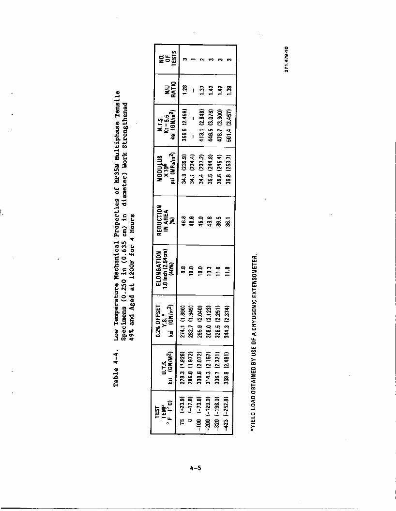
Mechanical Properties of Various Uetals Variation of Cvn for UP351 with Temperature Low Temperature Mechanical Properties of UP351 Uultiphase Tensile Specimens (0.250 in (0.635 cm) in diameter) Work Strengthened 49% and Aged at 1200F for 4 Hours
Variation of Size and Strength for UP351 Round Bar Stock
Manufacturer's Recommended Conditions for Machining UP351 Alloy Work Strengthened to 260 ksi (1793 UPa) Ultimate Tensile Stress
Manufacturer's Recommended Conditions for Surface Grinding
Comparison of Fabricated and Solid Sections
Candidate Sting Materials
Typical Composite Properties
Uaterial Properties for Hybrid Sting Configurations
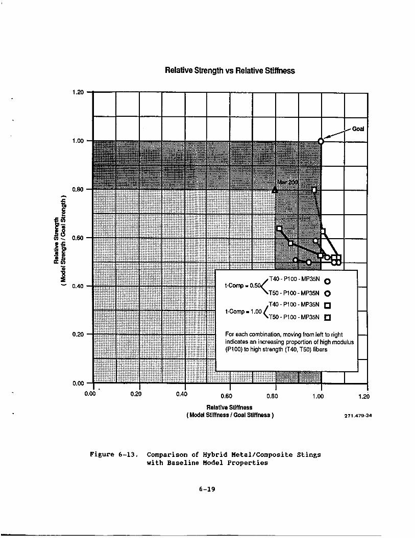
6-15
6-16
6-17
6-18
6-19
6-20
6-21
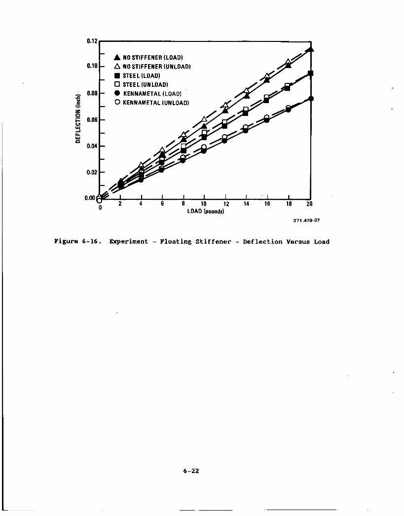
6-22
Paffa
3-3
3-6
4-1
4-4
4-4
4-5
4-6
4-7
4-8
4-14
5-2
5-8
6-4
vi
SECTION 1
IIRCRODUCTION
.
.
The inability of conventional wind tunnels to approach or match full scale Reynolds numbers led to the development of the National Transonic Facility (NTF) now in operation at NASA*s Langley Research Center. continuous flow, fan driven, high pressure facility, capable of operating at cryogenic temperatures.
A recent design study1*, investigated the feasibility of developing wind tunnel models of advanced fighter (highly maneuverable) models, for use in that facility. pointed out that test conditions (angle of attack/Reynolds number) for certain configurations is likely to be sting limited.
The NTF is a
The study indicated that such models could be developed, but
It has been recognized for some time that the sting (or support system) is a very critical part of the model system. the model designer is frequently faced with the tradeoff of minimizing the sting size, thereby compromising facility and model safety, against a larger sting and the subsequent problems of sting interference effects, and possible distortion of configuration geometry.
Even in conventional wind tunnels,
In the blTF this problem is accentuated by the severe environment of high pressure/low temperature, designed into the facility to provide the desired high Reynolds number. limiting the test envelope are therefore contrary to the purposes and goals of the IUTF and are unacceptable, hence the need for this study of advanced model support systems.
Compromises in the configuration geometry and/or
Present day wind tunnel support system technology dictates the use of a high grade steel sting. The low operating temperature (-300F) of the NTF, however, creates a severe environment for both the model and sting, and prohibits the use of most steels used in conventional wind tunnels. Toughness and ductility must be maintained at the low temperatures and this has led to the use of a maraging steel (18 Ni-200). Design studied have shown that the fighter type model when using a 18 Ni-200 sting is likely to have a limited test envelope due to sting divergence. than strength.
In other words, stiffness is more critical
1.1 DESIGN APPROACH
The goal of this study has been to investigate advanced sting materials, or combinations of materials that would give an improvement of 25% over 18 Ni-200 in both ultimate tensile strength, and Young's modulus of elasticity, E. Weight is a key factor; the steel sting is approximately 500 pounds, creating obvious handling problems. From this point of view a composite sting would be an attractive solution. From a strength/stiffness point of view, however, the value of the composite sting is questionable. Limited information is available at cryogenic temperatures; in addition, the majority of advanced structural work using composites has been for applications requiring a high
*Indicates reference. 1-1
strengthlweight ratio, resulting in thin wall designs. needs maximum strength/stiffness and within rea80n weight is a secondary issue.
The support system
Three basic approaches were taken to find a suitable material for the Advanced Sting for MTF:
a. Conventional material sting
b. Advanced composites
c. Hybrid configurations
Each approach had as its goal the following improvements in property levels:
a. Yield strength: 220-250 ksi at room temperature
b. Young's modulus: 32-35 Msi at room temperature
c. Charpy V-Notch (Cvn): 25 ft-lb at -320F
Before we discuss the results of each approach in detail, it would be instructive to first examine some of the known limitations of currently used materials.
1.2 TOUGHBIESS VERSUS STRENGTH LIMITATIONS
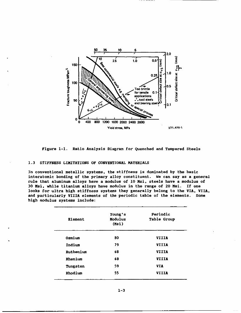
The current baseline material used in sting applications (18 Mi-200) has a yield strength of 200 ksi, a Young's modulus of 26.5 Hsi, and a Cvn toughness of 25 ft-lb at -320F. stiffness by 25% while maintaining the 25 ft-lb Cvn toughness at -320F. may not be difficult to achieve individual (strength or stiffness) requirements; it's difficult, however, to achieve both objectives simultaneously, while maintaining an acceptable toughness. Figure 1-1 shows the generally accepted relationship between strength and fracture toughness for commercially available structural alloys. be achieved but only through loss of toughness.
Our initial goal was to exceed 18 Ni-200 strength and It
Mote that higher strengths can
For a number of years-, materials developers have sought to find alloying combinations and microstructures that divert from the general inverse trend as shown in Figure 1-1. Today, precipitation hardening systems of iron, nickel, and cobalt represent the state of the art of high strength/toughness alloys. They form a family of alloys that combines excellent strength, adequate toughness, and relatively high stiffness.
Strength is generally achieved through a combination of solution hardening and precipitation hardening. In some systems, work hardening (i.e., increasing dislocation density through mechanical working) is also used to increase strength, often in conjunction with precipitation hardening.
In Design Approach 1, we examined in greater detail the kinds of refinements that might be made in the iron, cobalt, and nickel systems to achieve our required 25% improvement in strength and stiffness. These refinements included microstructural changes through powder metallurgy and thermal mechanical treatments.
Figure 1-1. Ratio Analysis Diagram for Quenched and Tempered Steels
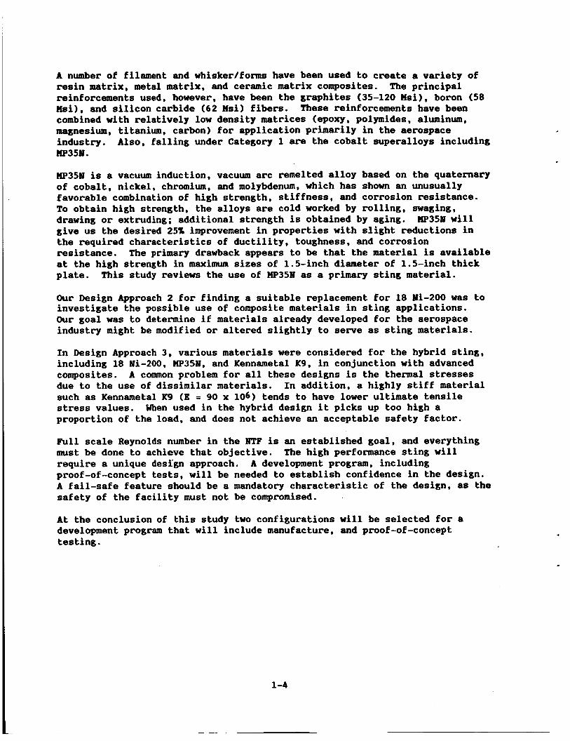
1.3 STIFFNESS LIMITATIONS OF COWENTIONAL MATERIALS
In conventional metallic systems, the stiffness is dominated by the basic interatomic bonding of the primary alloy constituent. rule that aluminum alloys have a modulus of 10 Msi, steels have a modulus of 30 Msi, while titanium alloys have modulus in the range of 20 Msi. If one looks for ultra high stiffness systems they generally belong to the VIA, VIIA, and particularly VIII-A elements of the periodic table of the elements. Some high modulus systems include:
We can say as a general
~~~
Element Young * s Periodic Modu 1 us Table Group (Wsi )
Osmium 80 VIIIA
Indium 79 VIIIA
Ruthenium 68 VIIIA
Rhenium 68 VIIIA
Tungsten 59 VIA
Rhodium 55 VIIIA
1-3
A number of filament and whiskerlfoms have been used to create a variety of resin matrix, metal matrix, and ceramic matrix composites. The principal reinforcements used, however, have been the graphites (35-120 Msi), boron (58 Msi), and silicon carbide (62 Wsi) fibers. These reinforcements have been combined with relatively low density matrices (epoxy, polymides, aluminum, magnesium, titanium, carbon) for application primarily in the aerospace industry. IIp35M.
Also, falling under Category 1 are the cobalt superalloys including
W35M is a vacuum induction, vacuum arc remelted alloy based on the quaternary of cobalt, nickel, chromium, and molybdenum, which has shown an unusually favorable combination of high strength, stiffness, and corrosion resistance. To obtain high strength, the alloys are cold worked by rolling, swaging, drawing or extruding; additional strength is obtained by aging. W35M will give us the desired 25% improvement in properties with slight reductions in the required characteristics of ductility, toughness, and corrosion resistance. at the high strength in maximum sizes of 1.5-inch diameter of 1.5-inch thick plate.
The primary drawback appears to be that the material is available
This study reviews the use of W35M as a primary sting material.
Our Design Approach 2 for finding a suitable replacement tor 18 Mi-200 was to investigate the possible use of composite materials in sting applications. Our goal was to determine if materials already developed for the aerospace industry might be modified or altered slightly to serve as sting materials.
In Design Approach 3, various materials were considered for the hybrid sting, including 18 Mi-200, W351, and Kennametal K9, in conjunction with advanced composites. A common problem for all these designs is the thermal stresses due to the use of dissimilar materials. such as Kennametal K9 (E = 90 x 106) tends to have lower ultimate tensile stress values. proportion of the load, and does not achieve an acceptable safety factor.
In addition, a highly stiff material
When used in the hybrid design it picks up too high a
Full scale Reynolds number in the NTF is an established goal, and everything must be done to achieve that objective. require a unique design approach. A development program, including proof-of-concept tests, will be needed to establish confidence in the design. A fail-safe feature should be a mandatory characteristic of the design, as the safety of the facility must not be compromised.
The high performance sting will
At the conclusion of this study two configurations will be selected for a development program that will include manufacture, and proof-of-concept testing.
1-4
SICTIOH 2
PROGRAH ORGANIZATIOY
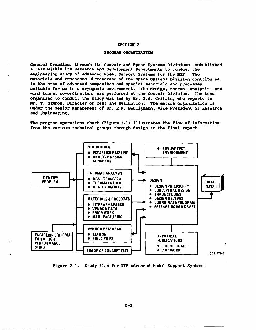
General Dynamics, through its Convair and Space Systems Divisions, established a team within its Research and Development Departments to conduct the engineering study of Advanced Hodel Support Systems for the NTF. The Haterials and Processes Directorate of the Space Systems Division contributed in the area of advanced composites and special materials and processes suitable for us in a cryogenic environment. The design, thermal analysis, and wind tunnel co-ordination, was performed at the Convair Division. The team organized to conduct the study was led by H r . S.A. Griffin, who reports to Hr. T. Sannnon, Director of Test and Evaluation. The entire organization is under the senior management of Dr. R . F . Beuligmann, Vice President of Research and Engineering.
The program operations chart (Figure 2-11 illustrates the flow of information from the various technical groups through design to the final report.
IDENTIFY I PROBLEM
FOR A HIGH
I PERFORMANCE I STING
REVIEWTEST STR U CTU RES
ANALYZE DESIGN - ESTABLISHBASELINE ENVIRONMENT
CONCERNS - I THERMAL ANALYSIS I4
DESIGN HEAT TRANSFER THERMAL STRESS HEATER REQMTS DESIGN PHILOSOPHY
CONCEPTUAL DESIGN I d I TRADESTUDIES
DESIGN REVIEWS COORDINATE PROGRAM PREPARE ROUGH DRAFT Y MATERIALS & PROCESSES
LITERARY SEARCH VENDORDATA
VENDOR RESEARCH LIAISON CI FIELDTRIPS
FINAL REPORT
TECHNICAL PUB LlCATlONS
ROUGHDRAFT ARTWORK
271.479-2
Figure 2-1. Study Plan for IJTF Advanced Model Support Systems
SECTIOM 3
ESTABLISHING CRITERIA FOR A HIGH PKRF0R)IMICE STING
Any sting designed for use in the NASA Langley Research facilities must meet the requirements established in the Wind Tunnel Model Systems Criteria2 handbook. and torsion, and the following divergence criteria: a safety factor of 2 against divergence demonstrated by in-depth analysis, and where possible, system stiffness verification.
These requirements include an adequate margin of safety in bending,
In this study, a goal was established, and a high performance sting was defined as one that could provide an improvement of 25% over the maraging steel (18 Mi-200) sting in ultimate tensile strength and Young's modulus of elasticity, E. These improvements must be achieved without adversely affecting fracture toughness at cryogenic temperatures. A Cvn of 25 ft-lb is desired.
Other desirable features:
0 A fail safe feature for a hybrid design
0 Reduced weight
0 Instrumentation to monitor stress/strain
0 Resistance to fatigue (fracture toughness) Resistance to corrosion
The structural analysis conducted for this program consisted of two phases. The first phase consisted of a study of the existing sting configuration to establish baseline performance goals. In the second phase, preliminary analysis was performed for several proposed alternative configurations. These configurations included high performance metals, advanced composite materials, and hybrid metal-composite combinations. For both of these efforts, the primary values considered were how the strength and stiffness of the various proposals compared to one another. directly in these comparisons but was instead treated as a initial screening mechanism. That is, materials that exhibited poor fracture toughness at cryogenic temperatures were eliminated From consideration before these studies were done to save time and narrow the range of potential candidates.
Fracture toughness was not considered
3.1 BASELINE CONFIGURATIOIJ STUDIES
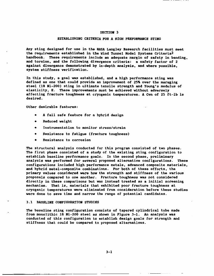
The baseline sting configuration consists of tapered cylindrical tube made from monolithic 18 Ni-200 steel as shown in Figure 3-1. conducted of this configuration to establish design goals for strength and stiffness that could be compared to proposed alternatives.
An analysis was
3-1
TI 1 I I 1
4 IN. 1 IN. I t I
I
I
7- 2 IN.
96 IN. STA 0.e
271.479-3 ( BASE'LI NE)
Figure 3-1. Generic Model Sting (Baseline)
3.1.1 STIFFNESS ANALYSIS. Plots of the stiffness versus length were generated for the existing sting and for the goal of a 25% improvement in these properties. calculated from the following equations:
The desired values were the AB and E1 terms and were
AE = s (Rg - Rf) (9)
E1 = */4 (Ri - Rf) (E)
where
Ro = 2.00 - ~/96.00
Ri = 0 .50
E = 26,500,000 psi (MIL-HDBK-SD, Table 2.5.1.0(b))
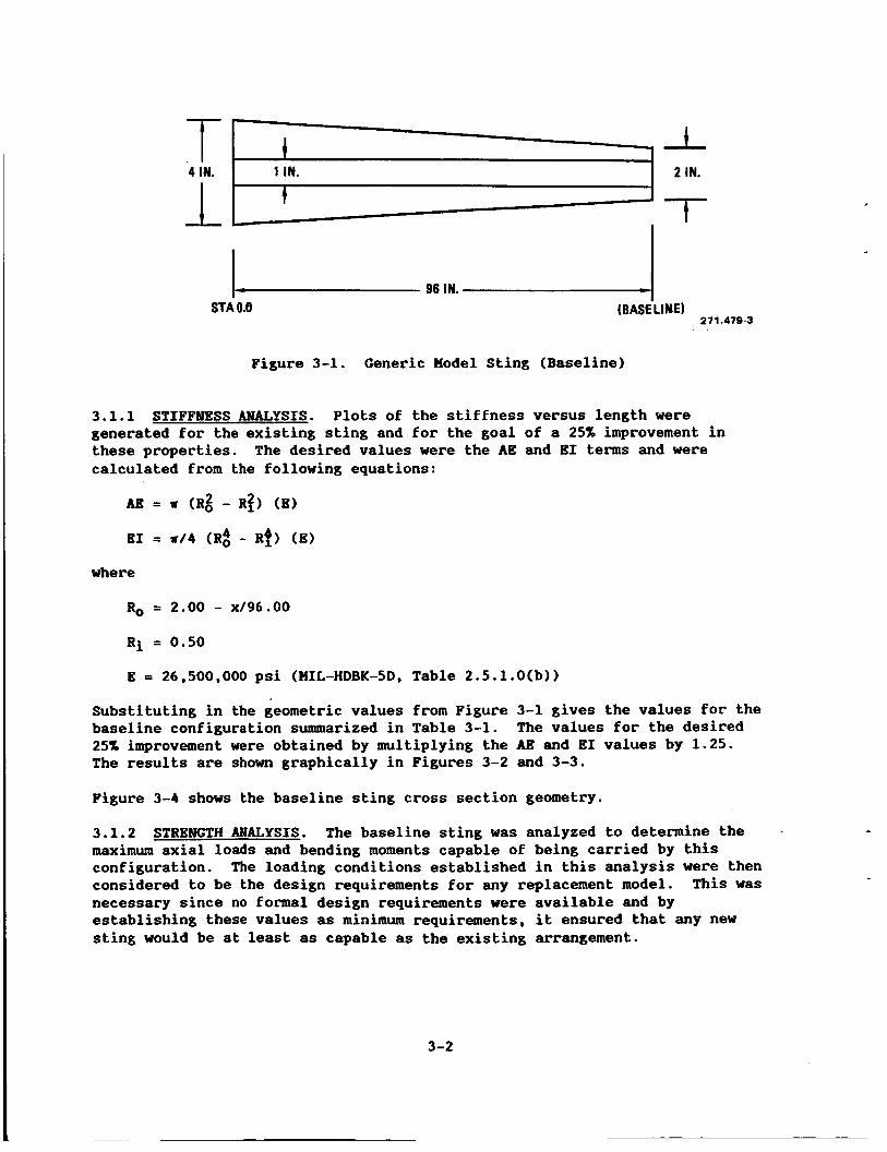
Substituting in the geometric values from Figure 3-1 gives the values for the baseline configuration summarized in Table 3-1. 25% improvement were obtained by multiplying the AB and E1 values by 1.25. The results are shown graphically in Figures 3-2 and 3-3.
Figure 3-4 shows the baseline sting cross section geometry.
3.1.2 STRENGTH ANALYSIS. maximum axial loads and bending moments capable of being carried by this configuration. considered to be the design requirements for any replacement model. necessary since no formal design requirements were available and by establishing these values as minimum requirements, it ensured that any new sting would be at least as capable as the existing arrangement.
The values for the desired
The baseline sting was analyzed to determine the
The loading conditions established in this analysis were then This was
Figure 3-2. Baseline and Improved Sting Configuration Stiffness Parameters, AB
The basic approach taken was to analyze the sections of the sting at the forward and aft ends to determine the maximum allowable axial loads and bending moments. baseline configuration using 18 Ni-200 and the desired 25% improvement. this, critical design conditions could be selected for use in the evaluating proposed configurations. A plot of the resulting design envelopes is shown in Figure 3-5 and a summary of the critical design conditions is given in the Table 3-2. Note that in selecting the critical design conditions at the aft end, the maximum axial load at the forward end was used as limiting value. This is because there is no means of introducing additional axial loads into the sting between the forward and aftends.
These were then used to create design envelopes for the From
Figure 3-3. Baseline and Improved Sting Configuration Stiffness Parameters, E1
271 A 7 9 6
Figure 3-4. Baseline Sting Cross Section Geometry
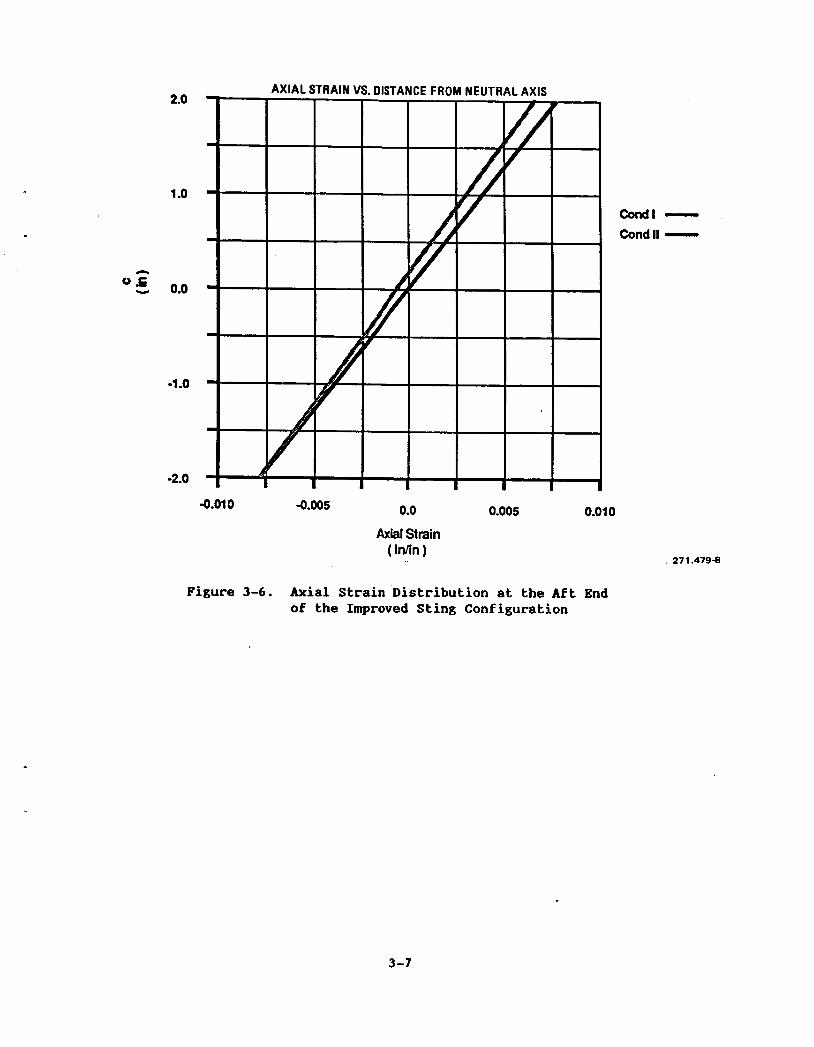
3.2 CROSS SECTION STRAIM DISTRIBUTIOM
The axial strains at the cross section at the aft end of the sting were calculated for the critical design conditions. analyzing potential sting configurations using hybrid material systems where the stress distribution at a given cross section would no longer be linear. The strain at a given location for a general section subjected to axial loads and bending moments is given by:
These values were required for
E = P/AE + Mc/EI The values for the improved sting configuration were used and were taken from Figures 3-2, 3-3, and 3-5. The results are shown in Figure 3-6.
3-4
n
4.0
3.0
2.0
1 .o
0.0
0.0 1 .o 1.5 0.5
Bending Moment (1,000,000 in-lbs )
2.0
271.479-7
Figure 3-5. Baseline and Improved Strength Design Envelope
3-5
Table 3-2. Critical Loading Conditions for the Improved Sting Configuration
Section Properties
A = w (Ro2 - Ri2) = w (1.002 - 0.502) I = ( # I 4 1 (Ro4 - Ri4) = ( # I 4 1 (1.004 - 0.504)
Internal Stresses
Ftu = PIA + mO/I P = A (Ftu - MRoI) ll = (IIRo) (Ftu - PIA)
Material Properties
18 Mi-200 E = 26,200,000 psi Ftu = 200,000 psi
Maximum Allowable Loads - Forward End
Section Properties Ro = 1.00 in. Ri = 0.50 in.
18 Ni-200 Pmax = 507,240 lb llmax = 147,260 in-lb
Maximum Allowable Loads - Aft End
Section Properties Ro = 2.00 in. Ri = 0.50 in.
18 Mi-200 Pmax = 2,536,200 lb
= 1,251,730 in-lb
Goal E = 32,750,000 psi Ftu = 250,000 psi
A = 2.5362 in2 I = 0.7363 in4
Goal Pmax = 634,050 lb Hmax = 184,075 in-lb
A = 11.7810 in2 I = 12.5173 in4
Goal Pm, = 2,945,250 lb P4,,, = 1,564,662 in-lb
Condition Axial Load (PI Bending Moment (MI (lb) (in-lb)
I 0 1,564,662 I1 -184 , 075 1 , 460 , 872
3 -6
2.0
1 -0
0.0
-1 .o
-2.0
0.0 0.005 0.01 0 -0.01 0 -0.005
Axial Strain ( inlin )
condl - CondII -
27 1.4794
Figure 3-6. Axial Strain Distribution at the Aft End of the Improved Sting Configuration
3-7
SBCTIOM 4 CONVENTIONAL METALLURGICAL APPROACH
4.1 GENERAL INFORIUTIOM
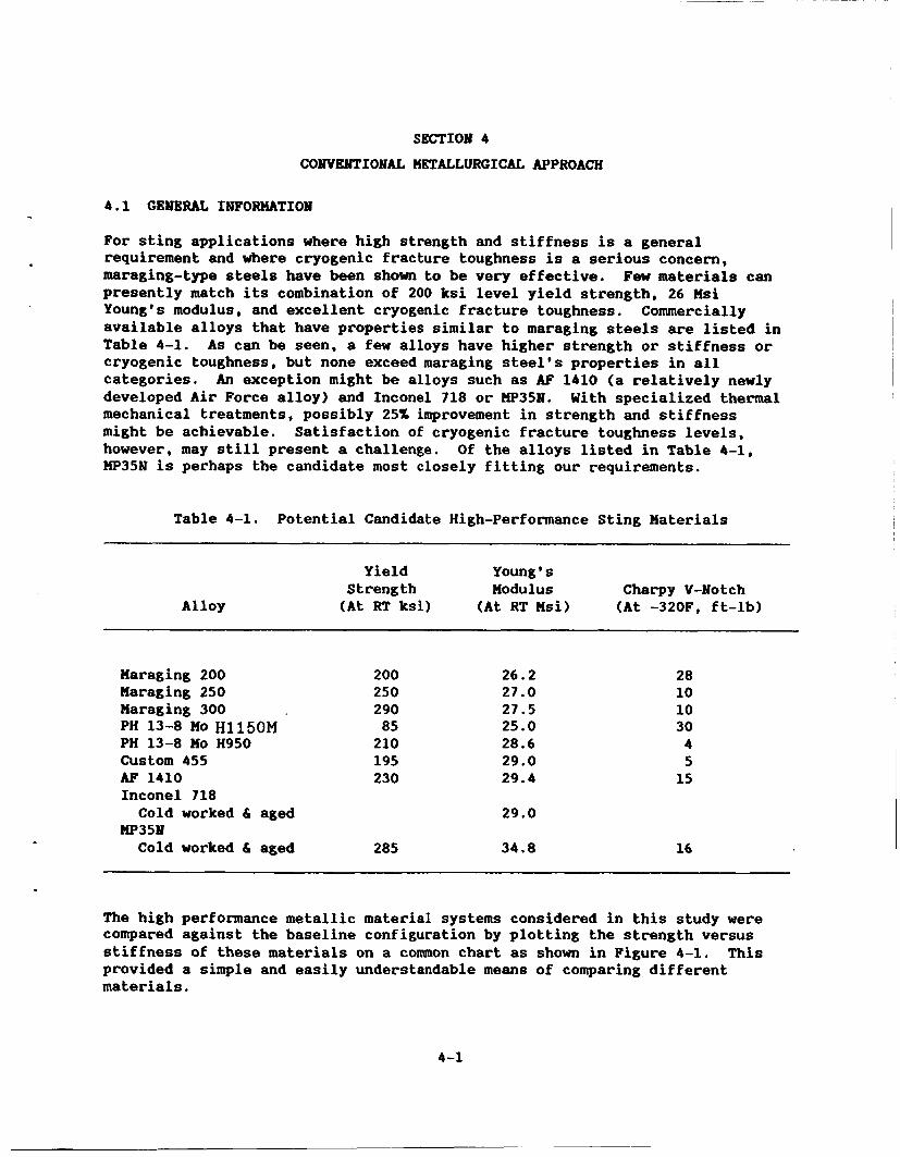
For sting applications where high strength and stiffness is a general requirement and where cryogenic fracture toughness is a serious concern, maraging-type steels have been shown to be very effective. Few materials can presently match its combination of 200 ksi level yield strength, 26 Msi Young's modulus, and excellent cryogenic fracture toughness. Commercially available alloys that have properties similar to maraging steels are listed in Table 4-1. cryogenic toughness, but none exceed maraging steel's properties in all categories. developed Air Force alloy) and Inconel 718 or W35N. With specialized thermal mechanical treatments, possibly 25% improvement in strength and stiffness might be achievable. however, may still present a challenge. Of the alloys listed in Table 4-1, HP35N is perhaps the candidate most closely fitting our requirements.
As can be seen, a few alloys have higher strength or stiffness or
An exception might be alloys such as AF 1410 (a relatively newly
Satisfaction of cryogenic fracture toughness levels,
Yield Young * s Strength Modulus Charpy V-Notch (At RT ksi) (At RT Msi) (At -320F, ft-lb)
Maraging 200 Maraging 250 Maraging 300 PH 13-13 MO ~ 1 1 5 0 ~ PH 13-8 MO H950 Custom 455 AF 1410 Inconel 718
HP351 Cold worked & aged
Cold worked & aged
200 250 290 85 210 195 230
285
26.2 27.0 27.5 25.0 28.6 29.0 29.4
29.0
34.8
28 10 10 30 4 5 15
16
The high performance metallic material systems considered in this study were compared against the baseline configuration by plotting the strength versus stiffness of these materials on a common chart as shown in Figure 4-1. This provided a simple and easily understandable means of comparing different materials.
4-1
600
500
400
300
200
100
0
Tensile Strength vs Tensile Modulus
60 80 100 120 0 20 40-
Tensile Modulus (300K) ( 1 O A 6 psi)
271.4799
Figure 4-1. Comparison of High Performance Metallic Materials
4-2
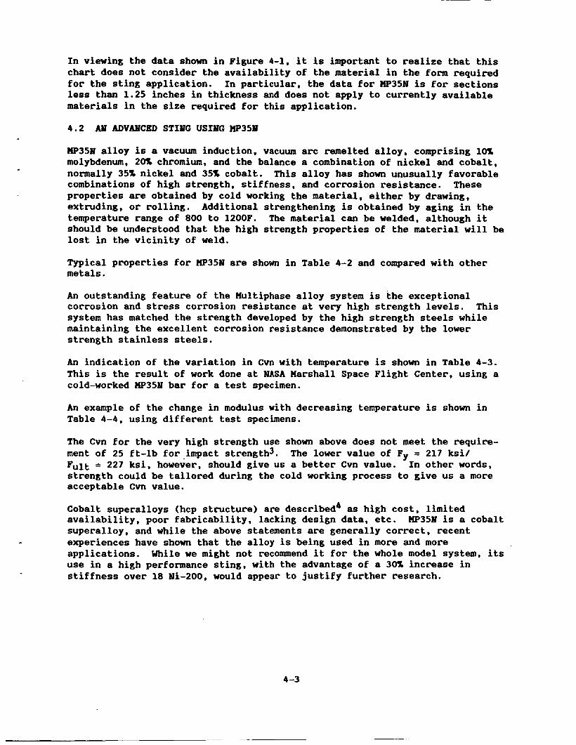
In viewing the data shown in Figure 4-1, it is important to realize that this chart does not consider the availability of the material in the form required for the sting application. In particular, the data for W35N is for sections less than 1.25 inches in thickness and does not apply to currently available materials in the size required for this application.
4.2 ADVANCED STING USING W35M
W35w alloy is a vacuum induction, vacuum arc remelted alloy, comprising 10% molybdenum, 20% chromium, and the balance a combination of nickel and cobalt, normally 35% nickel and 35% cobalt. This alloy has shown unusually favorable combinations of high strength, stiffness, and corrosion resistance. These properties are obtained by cold working the material, either by drawing, extruding, or rolling. temperature range of 800 to 1200F. should be understood that the high strength properties of the material will be lost in the vicinity of weld.
Additional strengthening is obtained by aging in the The material can be welded, although it
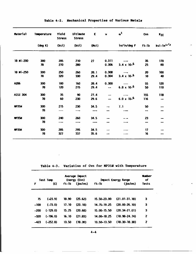
Typical properties for W35N are shown in Table 4-2 and compared with other metals.
An outstanding feature of the Hultiphase alloy system is the exceptional corrosion and stress corrosion resistance at very high strength levels. system has matched the strength developed by the high strength steels while maintaining the excellent corrosion resistance demonstrated by the lower strength stainless steels.
This
An indication of the variation in Cvn with temperature is shown in Table 4-3. This is the result of work done at NASA Marshall Space Flight Center, using a cold-worked W35N bar for a test specimen.
An example of the change in modulus with decreasing temperature is shown in Table 4-4, using different test specimens.
The Cvn for the very high strength use shown above does not meet the require- ment of 25 ft-lb for impact strength3. Fult = 227 ksi, however, should give us a better Cvn value. In other words, strength could be tailored during the cold working process to give us a more acceptable Cvn value.
Cobalt superalloys (hcp structure) are described4 as high cost, limited availability, poor fabricability, lacking design data, etc. PIP358 is a cobalt superalloy, and while the above statements are generally correct, recent experiences have shown that the alloy is being used in more and more applications. Wile we might not recommend it for the whole model system, its use in a high performance sting, with the advantage of a 30% increase in stiffness over 18 Ni-200, would appear to justify further research.
The lower value of Fy = 217 ksi/
4 -3
Table 4-2. Mechanical Properties of Various Metals
Material Tenperature Yield U1 timate E V a Cvn KIC t
stress stress
(deg IO (ksi) (ksi (Mi 1 in/in/deg F ft-lb ksi-in1'2
18 Ni-200 300 78
18 Ni-250 300 78
A286 300 78
A I S 1 304 300 78
w35N 300 78
" 300 78
m!iN 300 78
205 270
250 320
100 120
35 60
215 ---
240 --
285 327
210 280
260 330
160 215
90 230
230 -- 260 ---
295 337
27 0.311 0.306
28.1 0.308 29.4 0.304
28.4 0.300 29.4 -
27.4 - 29.6 -
35 25
20 10
55 50
1 55 116
50 --
23 - 17 16
1 70 80
100 40
120 110
118
I
- - -
- -
Table 4-3. Variation of Cvn for W 3 5 1 with Temperature
Average Inpact W r Test Tenp Energy (Om) Impact Energy Range of
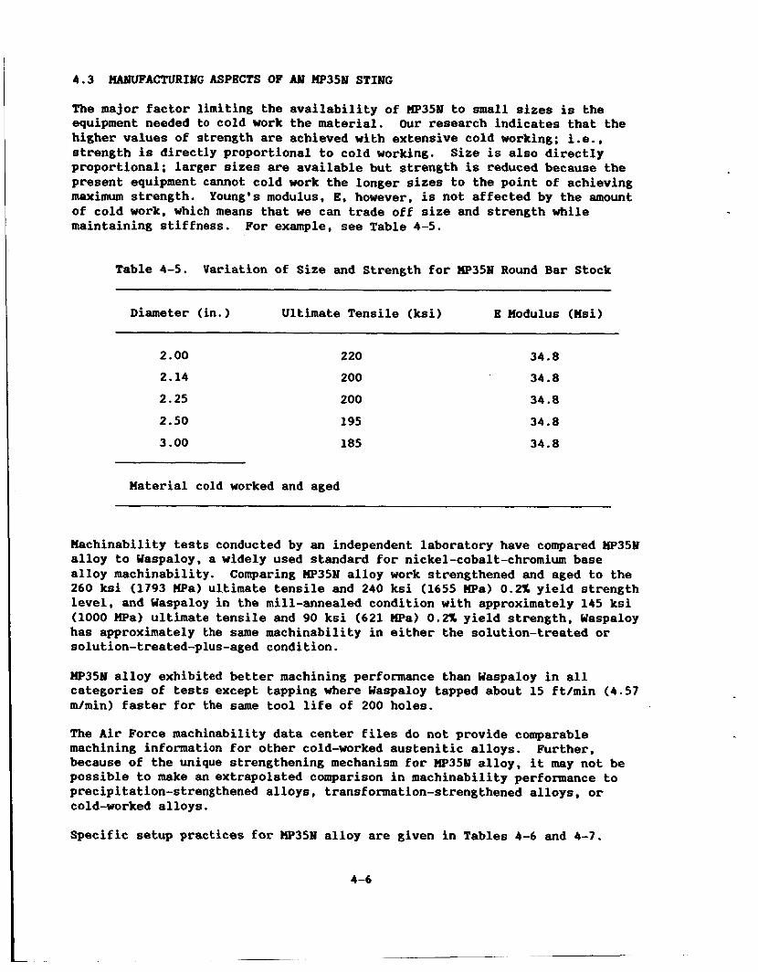
The major factor limiting the availability of HP35bl to small sizes is the equipment needed to cold work the material. Our research indicates that the higher values of strength are achieved with extensive cold working; i.e., strength is directly proportional to cold working. Size is also directly proportional; larger sizes are available but strength is reduced because the present equipment cannot cold work the longer sizes to the point of achieving maximum strength. Young's modulus, E, however, is not affected by the amount of cold work, which means that we can trade off size and strength while maintaining stiffness. For example, see Table 4-5.
Table 4-5. Variation of Size and Strength for "351 Round Bar Stock
Diameter (in. Ultimate Tensile (ksi) E Modulus (Msi)
2.00
2.14
2 .25
2 .50
220
200
200
195
34 .8
34 .8
3 4 . 8
34 .8
3 .00 185 34 .8
Material cold worked and aged
Machinability tests conducted by an independent laboratory have compared W351 alloy to Waspaloy, a widely used standard for nickel-cobalt-chromium base alloy machinability. Comparing XP35N alloy work strengthened and aged to the 260 ksi (1793 m a ) ul.timate tensile and 240 ksi (1655 m a ) 0.2% yield strength level, and Waspaloy in the mill-annealed condition with approximately 145 ksi (1000 m a ) ultimate tensile and 90 ksi (621 m a ) 0.2% yield strength, Waspaloy has approximately the same machinability in either the solution-treated or solution-treated-plus-aged condition.
MP35bl alloy exhibited better machining performance than Waspaloy in all categories of tests except tapping where Waspaloy tapped about 15 ft/min (4 .57 m/min) faster for the same tool life of 200 holes.
The Air Force machinability data center files do not provide comparable machining information for other cold-worked austenitic alloys. because of the unique strengthening mechanism for XP351 alloy, it may not be possible to make an extrapolated comparison in machinability performance to precipitation-strengthened alloys, transformation-strengthened alloys, or cold-worked alloys.
Further,
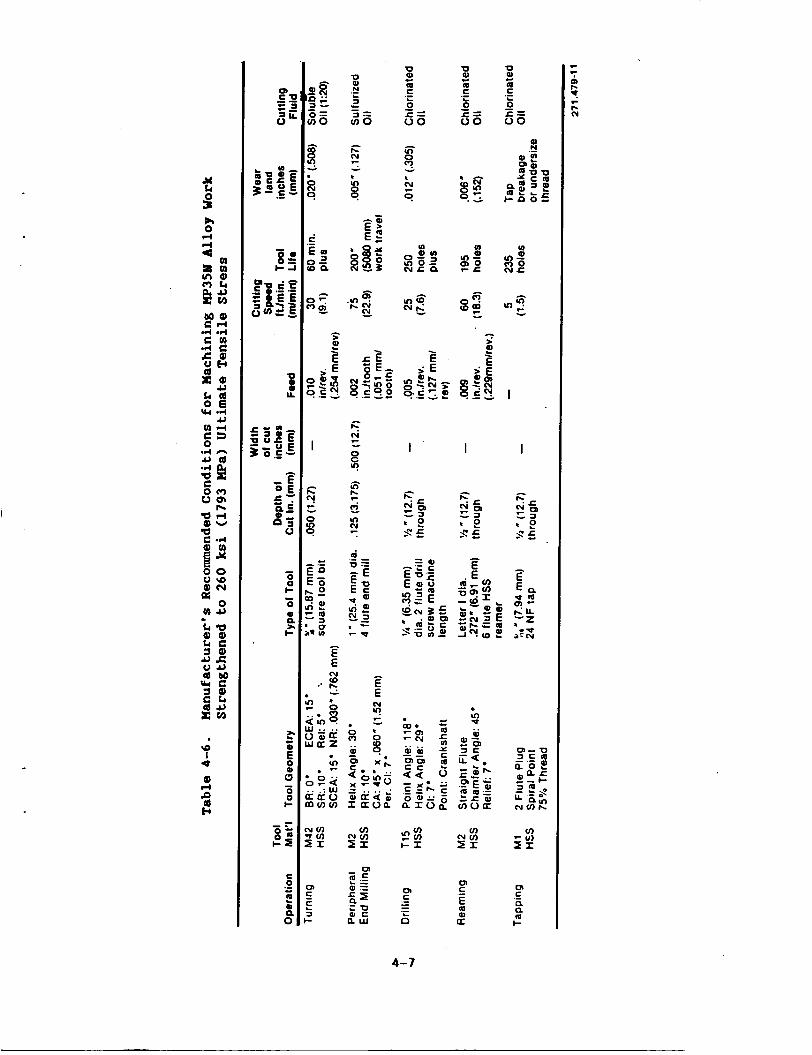
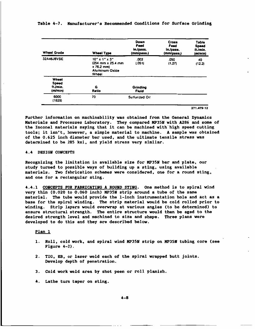
Specific setup practices for wP351s alloy are given in Tables 4-6 and 4-7.
4-6
I I
,
4-7
Table 4-7. Manufacturer's Recommended Conditions for Surface Grinding
Down Cross Trbls
hJp8SS. inJp888. ftJmin. Who01 Grrde Wheal Type (mmlprss.) (mmlpms.) (mlmin)
F0.d F O d sp..d
32A46J8VBE 10' x 1' x 3' . w 2 .050 40
x 76.2 mm) Aluminum Oxide Wheel
(254 mm x 25.4 mm (.051) (1.27) (12.2)
Whool
ftJmin. (mlmin)
sp..d G
Ratio Grinding
Fluid
6000 ( 1 829)
70 Sulfurized Oil
271.479-12
Further information on machinability was obtained from the General Dynamics Materials and Processes Laboratory. They compared W 3 5 N with A286 and some of the Inconel materials saying that it can be machined with'high speed cutting tools; it isn't, however, a simple material to machine. A sample was obtained of the 0.625 inch diameter bar used, and the ultimate tensile stress was determined to be 285 ksi, and yield stress very similar.
4.4 DESIGN CONCEPTS
Recognizing the limitation in available size for W 3 5 N bar and plate, our study turned to possible ways of building up a sting, using available materials. and one for a rectangular sting.
Two fabrication schemes were considered, one for a round sting,
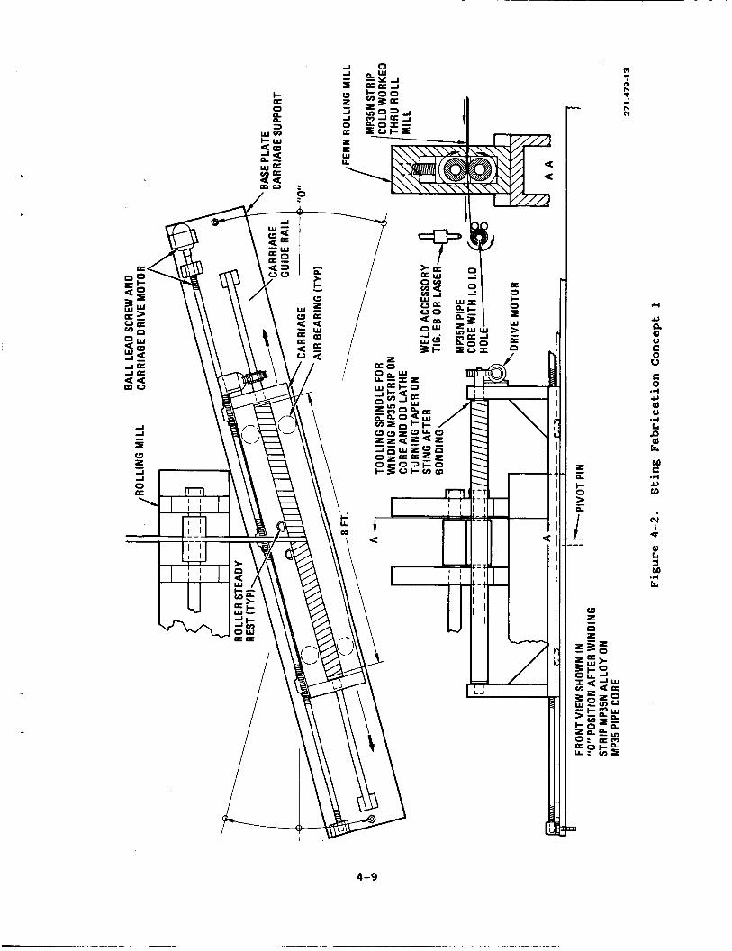
4.4.1 CONCEPTS FOR FABRICATING A R O W D STING. One method is to spiral wind very thin (0.020 to 0.060 inch) W35N strip around a tube of the same material. base for the spiral winding. winding. Strip layers would overwrap at various angles (to be determined) to ensure structural strength. desired strength level and machined to size and shape. developed to do this and they are described below.
The tube would provide the 1-inch instrumentation hole and act as a The strip material would be cold rolled prior to
The entire structure would then be aged to the Three plans were
Plan 1
1. Roll, cold work, and spiral wind W 3 5 N strip on W35N tubing core (see Figure 4-2).
2. TIG, EB, or laser weld each of the spiral wrapped butt joints. Develop depth of penetration.
3. Cold work weld area by shot peen or roll planish.
4 . Lathe turn taper on sting.
4-8
I /
rl
c) Q Q)
0 V c 0 .-I Y
x
(v I
U
4-9
I 5. Reweld top layer.
6.
Motes: Development data is need for cold working, TIG, BB, and laser
Age sting per Latrobe Steel specifications.
welding of W35M material.
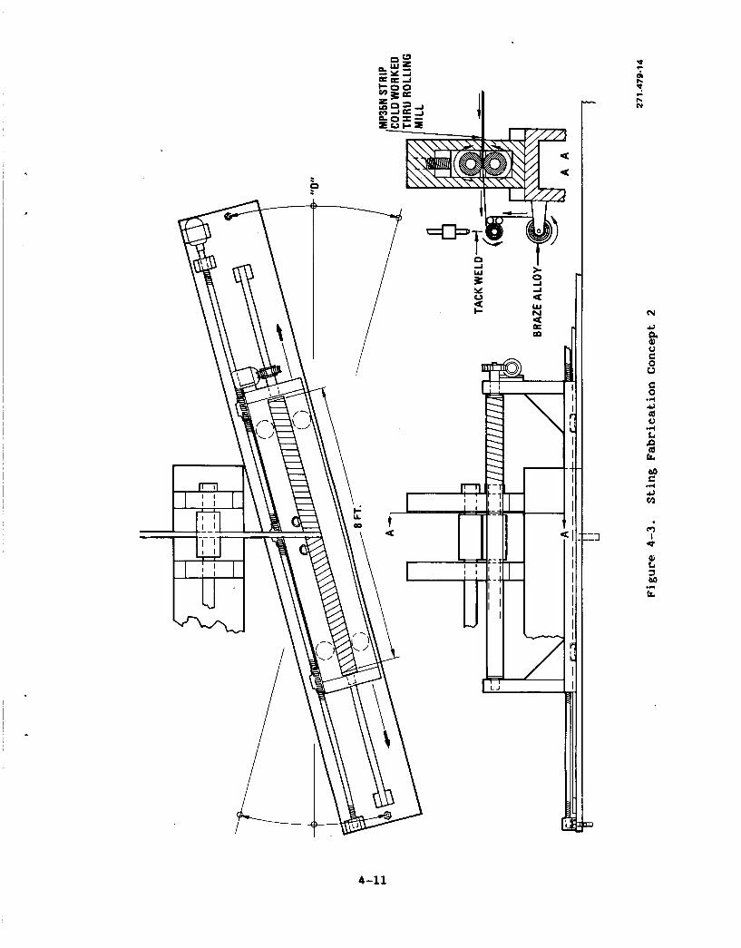
Plan 2
1. Roll, cold work, and spiral wind W35M strip material and braze alloy on W 3 5 N tubing core (see Figure 4-3).
2. Tack weld as required.
3. Vacuum or retort furnace braze. Hatch braze alloy to the W35M aging temperature (about 1000F).
Lathe turn taper on sting. 4.
Notes: Development data is need for cold working, brazing alloy selection, tack welding, and furnace brazing W35M material.
Plan 3
1. Roll, cold work, and spiral wind W35M strip on W35M tubing core.
2. Tack weld as required.
3. Diffusion weld entire sting together at a temperature to match the aging temperature.
4. Lathe turn taper on sting.
Notes: Development data is needed for cold working, tack welding, and diffusion bonding of m35M material.
The spiral wind process is a process that has been used successfully at GDC; it is described in a report5. inches wide by 0.60 inch thick) was wrapped around a tube, with an adhesive bond used for attachment. Cross plies were used for strength. tube wasl.0inches in diameter. la inch diameter mandrel using cold rolled W35M strips, a more difficult task. indicated in the plans above, electron-beam welding, brazing, and diffusion welding are alternate proposals. For either case the manufacturing process must be such that the cold worked properties of the strip are not lost. manufacturing process must therefore not exceed the aging temperature of W 3 5 1 (800 to 1200F).
In that particular case, stainless steel (3
The finished For the NTF application we must wrap over a
The cryogenic environment prohibits the use of an adhesive bond and as
The
4-10
L
I I
> s a
s A
w N
m
b0 c .d U m
cc) I
4-11
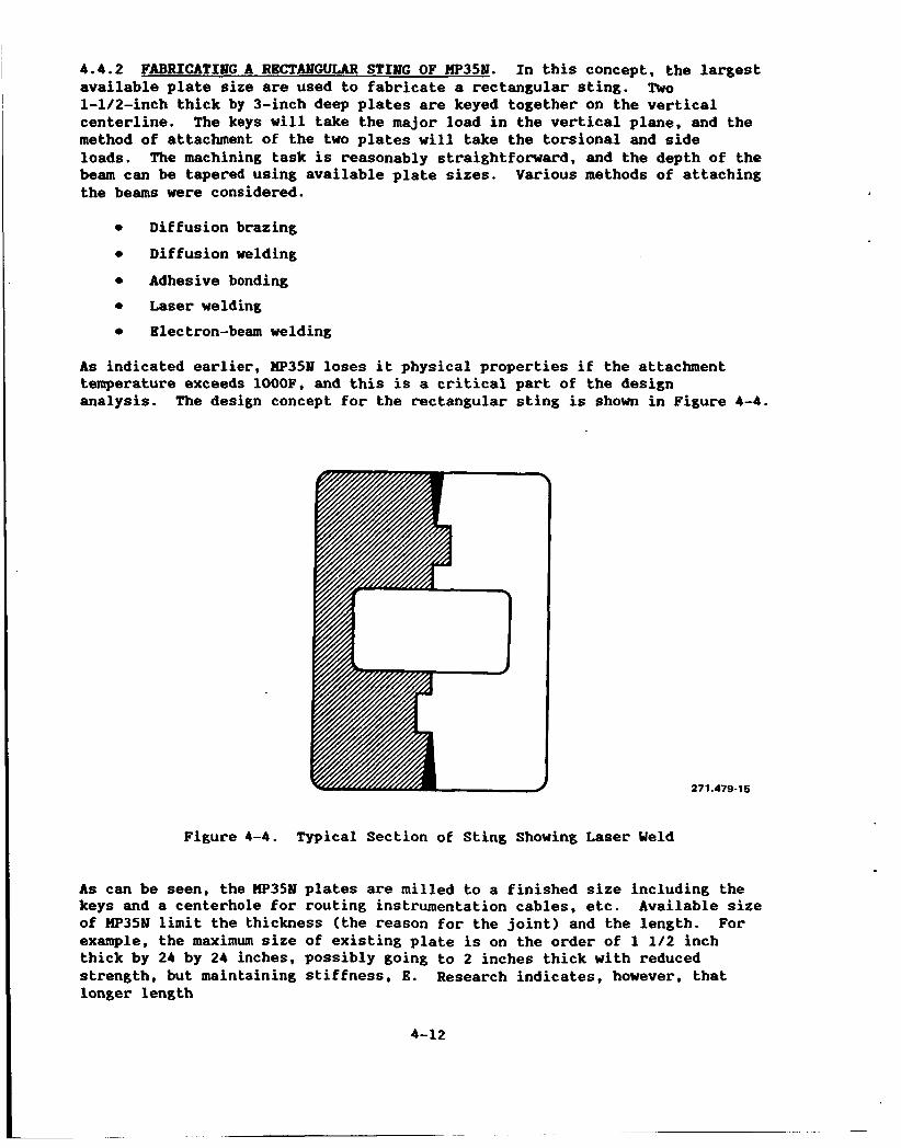
4.4.2 FABRICATIMG A RECTANGULAR STING OF Mp35M. In this concept, the largest available plate size are used to fabricate a rectangular sting. l-lle-inch thick by 3-inch deep plates are keyed together on the vertical centerline. method of attachment of the two plates will take the torsional and side loads. beam can be tapered using available plate sizes. the beams were considered.
TWO
The keys will take the major load in the vertical plane, and the
The machining task is reasonably straightforward, and the depth of the Various methods of attaching
As indicated earlier, UP35bl loses it physical properties if the attachment temperature exceeds 1000F, and this is a critical part of the design analysis. The design concept for the rectangular sting is shown in Figure 4-4.
271.479-16
Figure 4-4. Typical Section of Sting Showing Laser Weld
As can be seen, the W35N plates are milled to a finished size including the keys and a centerhole for routing instrumentation cables, etc. of W 3 5 1 limit the thickness (the reason for the joint) and the length. For example, the maximum size of existing plate is on the order of 1 112 inch thick by 24 by 24 inches, possibly going to 2 inches thick with reduced strength, but maintaining stiffness, E. Research indicates, however, that longer length
Available size
4-12
(4 or 5 feet) could be obtained in the future, but is a function of equipment, demand, etc. It is not unreasonable, therefore, to think in terms of sting 2 to 3 inches wide by 3 to 6 inches deep by 5 feet long, fabricated from two plates. test.
The design concept must therefore be developed in proof-of-concept
Attachment method analysis follows.
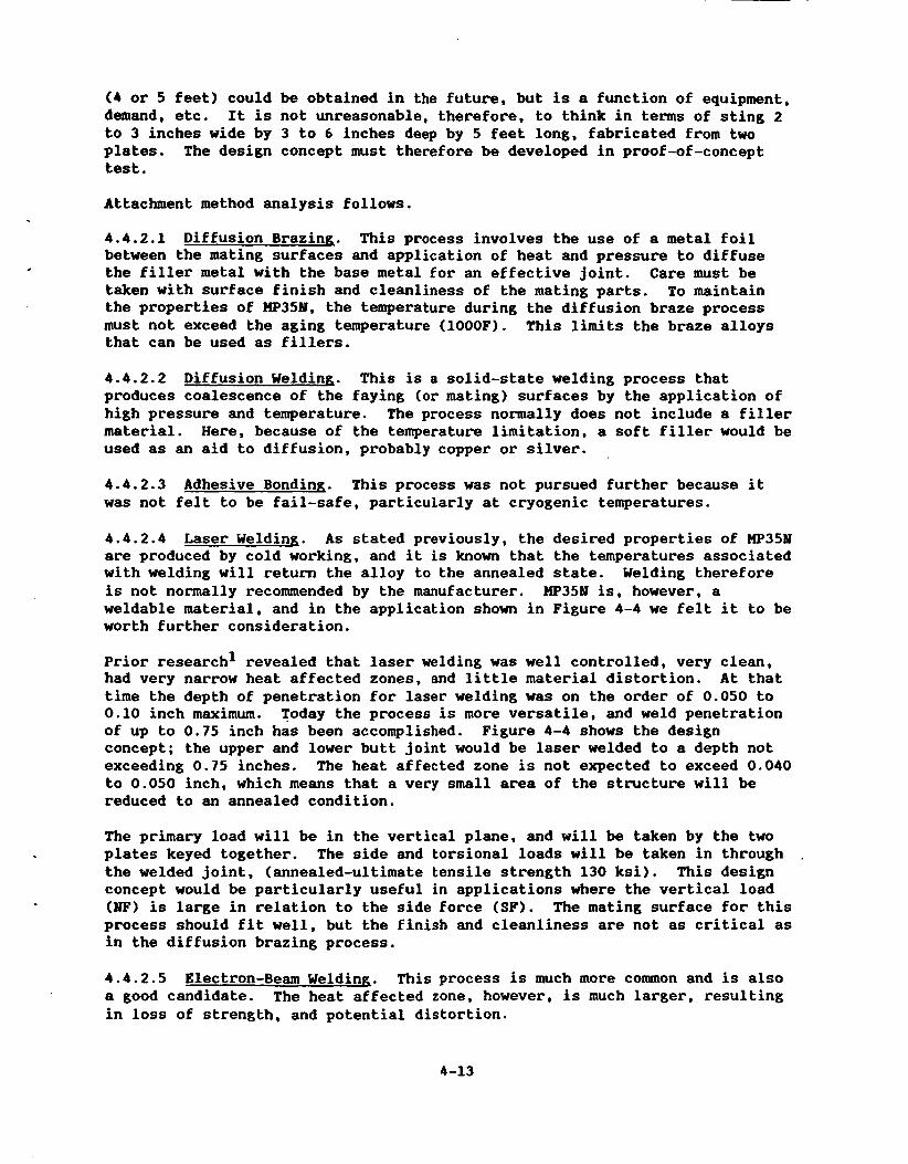
4 . 4 . 2 . 1 Diffusion Brazing. This process involves the use of a metal foil between the mating surfaces and application of heat and pressure to diffuse the filler metal with the base metal for an effective joint. Care must be taken with surface finish and cleanliness of the mating parts. To maintain the properties of )Ip35IV, the temperature during the diffusion braze process must not exceed the aging temperature (1000F). This limits the braze alloys that can be used as fillers.
4 .4 .2 .2 Diffusion Welding. This is a solid-state welding process that produces coalescence of the faying (or mating) surfaces by the application of high pressure and temperature. The process normally does not include a filler material. Here, because of the temperature limitation, a soft filler would be used as an aid to diffusion, probably copper or silver.
4 .4 .2 .3 Adhesive Bonding. This process was not pursued further because it was not felt to be fail-safe, particularly at cryogenic temperatures.
4 .4 .2 .4 Laser Welding. As stated previously, the desired properties of Hp351 are produced by cold working, and it is known that the temperatures associated with welding will return the alloy to the annealed state. Welding therefore is not normally recommended by the manufacturer. W 3 5 1 is, however, a weldable material, and in the application shown in Figure 4-4 we felt it to be worth further consideration.
Prior research1 revealed that laser welding was well controlled, very clean, had very narrow heat affected zones, and little material distortion. At that time the depth of penetration for laser welding was on the order of 0.050 to 0.10 inch maximum. Today the process is more versatile, and weld penetration of up to 0.75 inch has been accomplished. concept; the upper and lower butt joint would be laser welded to a depth not exceeding 0.75 inches. The heat affected zone is not expected to exceed 0.040 to 0.050 inch, which means that a very small area of the structure will be reduced to an annealed condition.
Figure 4-4 shows the design
The primary load will be in the vertical plane, and will be taken by the two plates keyed together. The side and torsional loads will be taken in through ,
the welded joint, (annealed-ultimate tensile strength 130 ksi). This design concept would be particularly useful in applications where the vertical load (NF) is large in relation to the side force (SF). The mating surface for this process should fit well, but the finish and cleanliness are not as critical as in the diffusion brazing process.
4 . 4 . 2 . 5 Electron-Beam Welding. This process is much more common and is also a good candidate. The heat affected zone, however, is much larger, resulting in loss of strength, and potential distortion.
4-13
4.5 STRUCTURAL MALYSIS
L
The sting cross-section shown in Figure 4-4 is a typical design concept. vertical load is normally larger and is taken equally by the two plates. keyways help to locate the plates, and take out any asymmetric loading. centerhole used for routing wiring, tubes, etc., would be rectangular, with the short axis in the vertical plane for increased moment of inertia. laser welded butt joint would vary in depth up to a maximum of 0.75 inch.
?he The The
The
Table 4-8 is a comparison of the fabricated section as shown with a solid section of the same material.
Table 4-8. Comparison of Fabricated and Solid Sections
Load Fabricated Solid
Vertical Strength reduced by depth of Maximum strength of full section weld times 0.050 inch (annealed).
Side Taken by shear at welded surf ace
Maximum strength of full section
Torsion Similar to side load As above
An alternate design for the rectangular sting was considered. purpose was to use available material for a longer sting. thicker plates are limited in length to 2 feet, whereas sheet stock to thicknesses of 1/4 inch are available in lengths of 6 feet. The alternate design is a laminated beam comprising strips of 1/4-inch sheet built up to the desired width, with the strips cut to the depth required.
The main At present the
The key to fabrication of this type of beam is the joining process. Various methods were described earlier in the section and of those, diffusion welding is felt to be one of the best candidates. As described earlier, a 0.003-inch thick film of copper or silver would be placed between the sheets of )Ip35N, and pressure applied at a temperature not exceeding 1000F. This process does not include macroscopic deformation, or melting of the filler.
As described in several welding journal articles6, the process is diffusion welding if the interlayers do not melt. successfully accomplished using 18 Mi-200, development would be required using HP35N. diffusion welding process.
While this process has been
The use of comparatively thin sheets of HP35N would facilitate the Figure 4-5 shows the concept.
4-14
CAP, 4 1/4lN.
SIDE
Figure 4-5. Rectangular Beam Using 1/4-inch LIP351 Strip
271 A7946
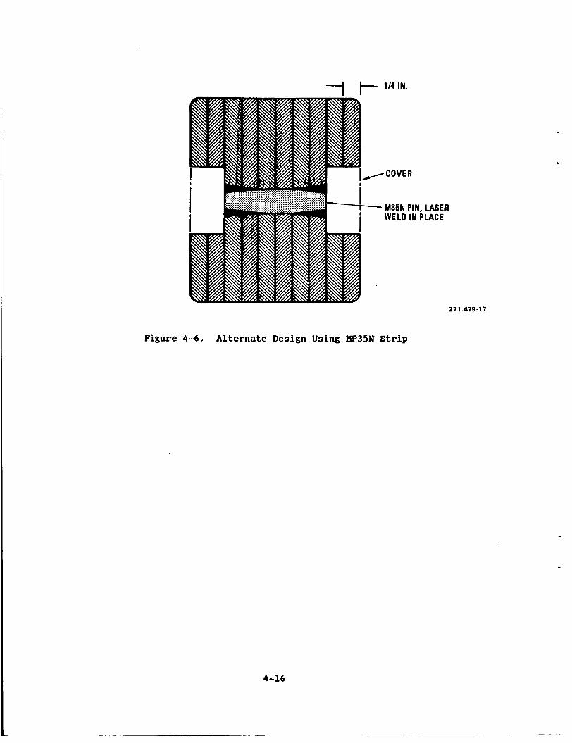
To create a hole in the center for routing model instrumentation, it may be necessary to subassemble the sides, and top and bottom caps. Alternatively, instrumentation could be routed along the sides as shown in Figure 4-6, with an outer cover for protection. As a conservative measure (fail-safe) a pin could be used across the center, laser welded in place for positive clamping of the W35Y strips.
The design using multiple shemts of W351 is potentially stronger than the two plate approach shown in Figure 4-4 because the thin sheets can be cold worked to the full allouables; in addition, the diffusion welding at 10001 will not reduce the properties.
4-15
4 1/4 IN.
.COVER
M35N PIN, LASER WELD IN PLACE
27 1.479-1 7
Figure 4-6. Alternate Design Using W 3 5 N Strip
4-16
SECTION 5
THE USE OF ADVMCED COHPOSITES FOR A HIGH PERFORMAMCE STING
5.1 GENERAL, INFORMTION
In viewing the use of composites for use in a high performance sting, it is found that the majority of development work has been done in the area of high strength-to-weight ratios, in other words, relatively thin walled structures. The sting is essentially a solid bar, with a small centerhole, and the generally accepted properties for composites probably do not apply. purposes of their study, however, our goal was to review composite materials developed for the aerospace industry, and to determine if they could be modified or altered for use in a sting application.
For
5.2 ORGANIC MATRIX COMPOSITES
In the search for high modulus organic composites, the properties of pitch-based graphite fibers were considered because of their moduli of 70 to 125 Hsi. The fibers, as they are currently available, will produce epoxy matrix laminates with moduli of about 70 Hsi. However, the tensile strengths of these composites are only 180 ksi. Some of the intermediate modulus PAN-based polyacylonitrile fibers will produce laminates with moduli of about 25 Hsi and tensile ultimates of 400 ksi. In compression, however, the PAN-based laminates show ultimates of only 140,000 psi maximum and the pitch-based laminates 40,000 psi and are erratic in performance.
The properties of graphite fiber composites show promise if they can be used in such a manner that they are loaded only in tension.
In this study of advanced stings, the primary load is nearly always in the upward direction. The sting is a cantilevered beam; therefore, the upper side is in compression, and the lower in tension. The feasibility of using an all-composite sting was reviewed on that basis. Unfortunately, there doesn't seem to be any obvious way to blend the material so that we use the high tensile modulus of pitch fibers along with the high tensile strength of PAM fibers. in strain rates between the two types of fibers. Table 5-1 lists candidate materials.
Combining them did not seem to be feasible because of the differences
Since the ultra high modulus graphite structures are unpredictable when loaded in compression, and the high-modulus, high strength graphites are not as attractive when loaded in other than tension, any improvement in properties over the metallic materials must be gained by loading them only in tension. These limitations make the design of an all-organic matrix structure very difficult and lead to the alternative of incorporating them into a hybrid design with metallic elements.
5-1
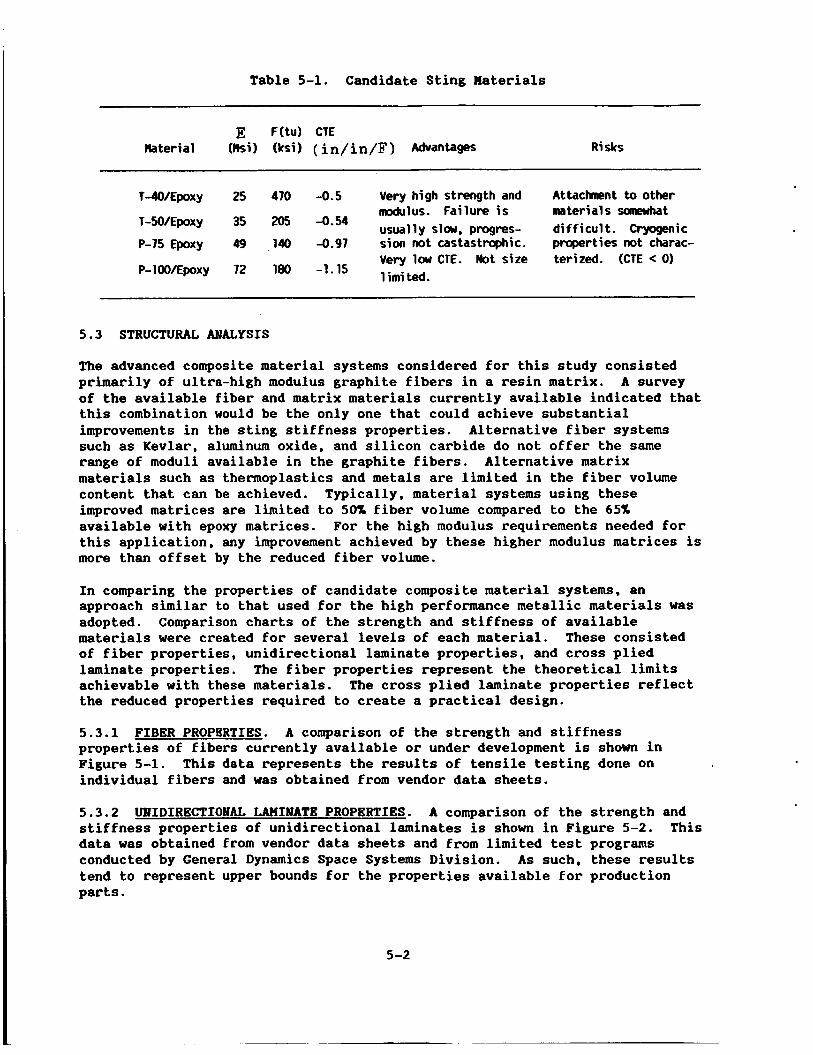
Table 5-1. Candidate Sting Materials
Risks
T-clO/Epoxy 25 470 -0.5 Very high strength and Attachent to other nrodulus. Failure i s materials sanewhat usually slaw, progres- di f f icul t . Cryogenic T-SO/Epoxy 35 205 4-54
P-75 Epoxy 49 140 -0.97 sion not castastrophic. properties not charac- Very low CTE. Not sire terized. (CTE < 0 ) 1 i m i ted. P-lW/EpoXy 72 180 -1.15
5.3 STRUCTURAL MlALYSIS
The advanced composite material systems considered for this study consisted primarily of ultra-high modulus graphite fibers in a resin matrix. of the available fiber and matrix materials currently available indicated that this combination would be the only one that could achieve substantial improvements in the sting stiffness properties. Alternative fiber systems such as Kevlar, aluminum oxide, and silicon carbide do not offer the same range of moduli available in the graphite fibers. materials such as thermoplastics and metals are limited in the fiber volume content that can be achieved. Typically, material systems using these improved matrices are limited to 50% fiber volume compared to the 65% available with epoxy matrices. this application, any improvement achieved by these higher modulus matrices is more than offset by the reduced fiber volume.
A survey
Alternative matrix
For the high modulus requirements needed for
In comparing the properties of candidate composite material systems, an approach similar to that used for the high performance metallic materials was adopted. materials were created for several levels of each material. These consisted of fiber properties, unidirectional laminate properties, and cross plied laminate properties. The fiber properties represent the theoretical limits achievable with these materials. the reduced properties required to create a practical design.
Comparison charts of the strength and stiffness of available
The cross plied laminate properties reflect
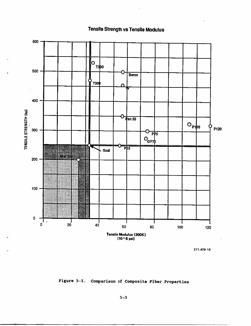
5.3.1 FIBBR PROPERTIES. A comparison of the strength and stiffness properties of fibers currently available or under development is shown in Figure 5-1. individual fibers and was obtained from vendor data sheets.
This data represents the results of tensile testing done on
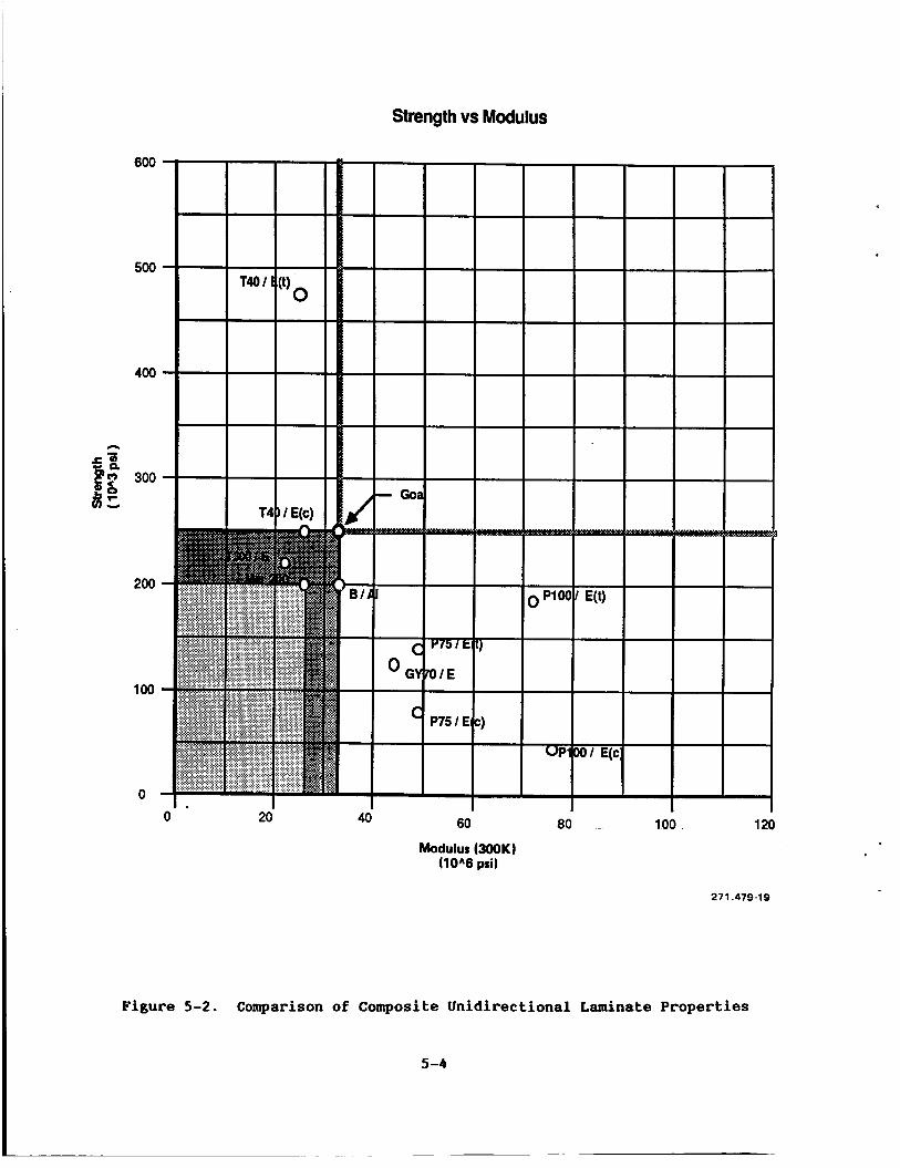
5.3.2 ~IDIRBCTIOMAL M I M A T B PROPERTIIS. A comparison of the strength and stiffness properties of unidirectional laminates is shown in Figure 5-2. This data was obtained from vendor data sheets and from limited test programs conducted by General Dynamics Space Systems Division. tend to represent upper bounds for the properties available for production parts.
As such, these results
5-2
600
500
400
2 - I I- (3 LI w
300 k w -I
L w + 3j
200
100
0
Tensile Strength vs Tensile Modulus
I P120
60 80 100 120
Tensile Modulus (300K) (10 A 6 psi)
271.479-18
Figure 5-1. Comparison of Composite Fiber Properties
5-3
600
500
400
300
200
100
0
Strength vs Modulus
60 80 . 100 1 20 0 20 40
Modulus (300K) (10A6 psi)
271.479-19
Figure 5-2. Comparison of Composite Unidirectional Laminate Properties
5-4
There are two factors to note when comparing this chart to the one for fiber properties. both improved strength and stiffness properties compared to the existing sting. substantially less than their tensile strengths. for the ultra-high modulus materials that have only a limited tensile strength to begin with. one-third to one-half of the tensile strength. testing done for an unrelated program and represents a definite limitation on the application of these materials.
The first is that there is no longer any one system that achieves
The second is that the compressive strengths of these materials are This is especially notable
For these materials, the compressive strength is only This data was confirmed by
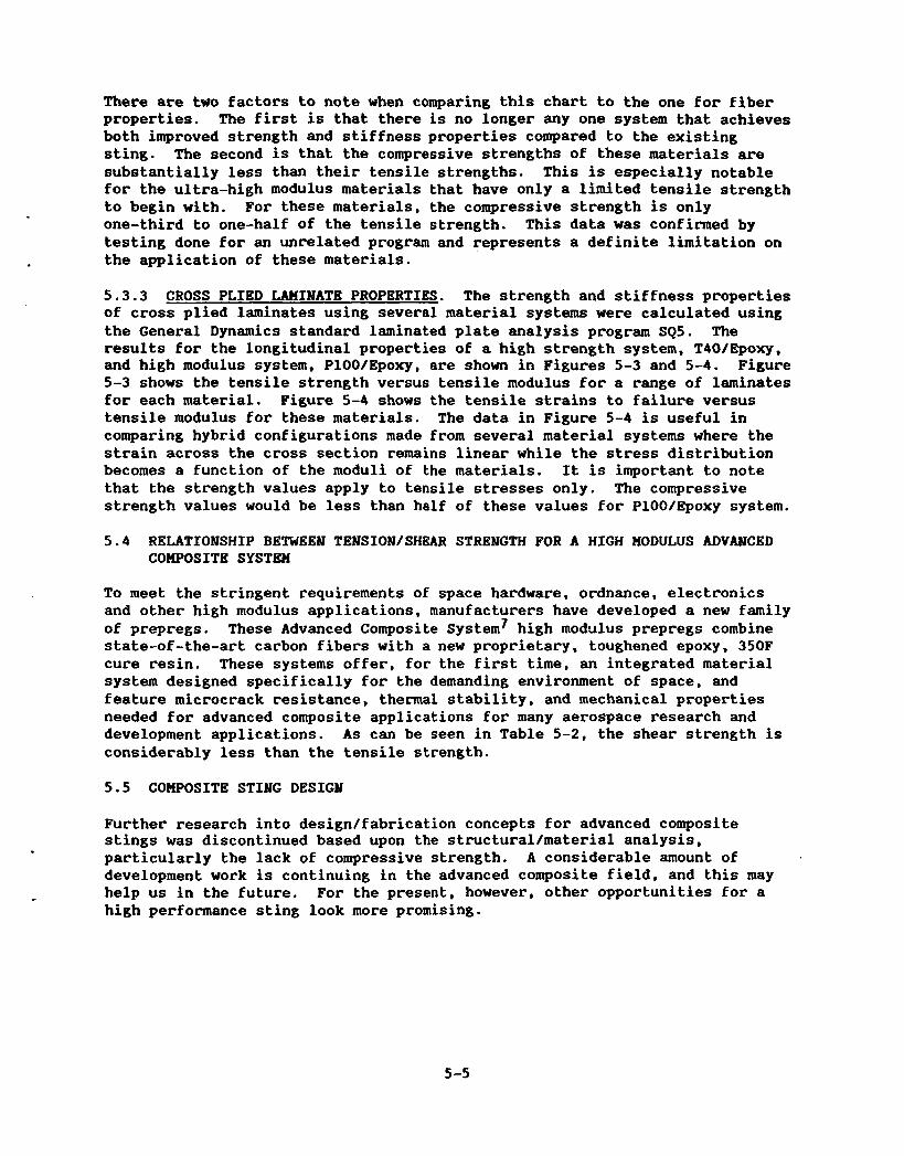
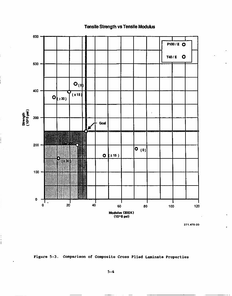
5.3.3 CROSS PLIED LAMINATE PROPERTIES. The strength and stiffness properties of cross plied laminates using several material systems were calculated using the General Dynamics standard laminated plate analysis program SQS. results for the longitudinal properties of a high strength system, T40/Epoxy, and high modulus system, PlOO/Epoxy, are shown in Figures 5-3 and 5-4. Figure 5-3 shows the tensile strength versus tensile modulus for a range of laminates for each material. Figure 5-4 shows the tensile strains to failure versus tensile modulus for these materials. The data in Figure 5-4 is useful in comparing hybrid configurations made from several material systems where the strain across the cross section remains linear while the stress distribution becomes a function of the moduli of the materials. It is important to note that the strength values apply to tensile stresses only. The compressive strength values would be less than half of these values for PlOO/Epoxy system.
The
5.4 RELATIONSHIP BETWEEN TENSION/SHBAR STRENGTH FOR A HIGH MODULUS ADVANCED COMPOSITE SYSTEM
To meet the stringent requirements of space hardware, ordnance, electronics and other high modulus applications, manufacturers have developed a new family of prepregs. These Advanced Composite System7 high modulus prepregs combine state-of-the-art carbon fibers with a new proprietary, toughened epoxy, 350F cure resin. These systems offer, for the first time, an integrated material system designed specifically for the demanding environment of space, and feature microcrack resistance, thermal stability, and mechanical properties needed for advanced composite applications for many aerospace research and development applications. considerably less than the tensile strength.
As can be seen in Table 5-2, the shear strength is
5.5 COMPOSITE STING DESIGY
Further research into design/fabrication concepts for advanced composite stings was discontinued based upon the structural/material analysis, particularly the lack of compressive strength. A considerable amount of development work is continuing in the advanced composite field, and this may help us in the future. For the present, however, other opportunities for a high performance sting look more promising.
5 -5
Tensile Strength vs Tensile Modulus
600
500
400
A
200
100
0
0 20 40 60 80 100 120
Modulus W O K ) ( 1 0 A 6 psi)
271.479-20
Figure 5-3. Comparison of Composite Cross Plied Laminate Properties
5-6
i 20
Tensile Strain vs Tensile Modulus
0.024
0.020
0.01 6
0.01 2
0.008
0.004
0
60 80 40
Modulus (300K) (10A6 psi)
1 ao 120
271.479-21
Figure 5-4. Comparison of Composite Cross Plied Laminate Properties
5-7
I Table 5-2. Typical Composite Properties
Property Pitch Fiber composi test
P-55 P-75 P-100
Longitudinal Tension (ASTM D-3039)
Strength (ksi) Strain ( X I Modulus (Msi)*t Poisson’s Ratio
In a previous wind tunnel model study1 by General Dynamics the limitation of the sting was recognized and a section describing an "ideal" sting was included: excerpts from that section follow as they form the basis for the research into the feasibility of a hybrid sting.
"The primary objective of this section of the study is to identify advanced materials, or combinations of materials, that will provide increased strength and stiffness properties at cryogenic temperatures. factor; the steel sting is approximately 500 pounds, creating obvious handling problems. attractive.
Weight is also a key
From this point of view, composites would appear to be very
"During the materials research, it was quickly discovered. that very little information is available on material properties at the cryogenic temperatures of the NTF. Furthermore, much of the available information is for small billets, and for composite materials for thins sections. For example, considerable research has been done in the aerospace industry on the use of composite materials for space applications at low temperature. High strength boron/aluminum tubes and various graphite epoxies have been developed; in space applications, however, the thrust has been to develop high strengthlweight ratios, and therefore the materials are relatively thinwalled. In sting applications, the material thickness is much greater, resulting in questionable material properties, and much higher manufacturing costs.
"One material possessing interesting properties in Kennametal K9, a tungsten alloy with a stiffness three times that of steel. Again, very little information is available for this material at cryogenic temperatures. Kennametal, Inc., conducted a study of the feasibility of using Kennametal K9 as a sting material. The study revealed that the strength and stiffness of K9 was considerably less than the published values when applied to the physical size of material required to manufacture the sting. The properties had been developed from relatively small test samples, and the manufacturer, while initially optimistic, later determined that the desired characteristics of K9 would be degraded to an unacceptable level for an item with the physical size of an NTF sting. Our research also showed that there would be manufacturing . problems associated with producing a K9 sting suitable for the NTF. Degradation of material properties due to size was, however, the key factor in determining the unsuitability of Kennametal K9.
"As an alternative to a sting manufactured completely of Kennametal K9, our study turned to the use of Kennametal K9 with its desirable stiffness properties combined with other high strength materials. an A286 inner core was investigated, but again the K9 shell was found to be so
A K9 outer shell and
6-1
large that properties were questionable and manufacture a problem. K9 as an inner core rather than an outer shell was also considered.
Using the
"General Dynamics then investigated the use of a high grade steel such as 18 11-200, or Kennametal K9, with advanced composites such as boron/aluminum, or graphite epoxies. Finally a combination of Kennametal K9, boron/aluminum, and 18 Ni-200 steel was considered. A common problem (for all these sting designs using dissimilar materials) is that of coefficient of expansion, and the resulting thermal stresses. and coefficients and shows a schematic of an "ideal" sting, combining the best available materials. In design, however, it was found that the stiff Kennametal K9 (modulus of elasticity = 90 x lo6) became too highly stressed, due to picking up too high a proportion of the total load applied to the sting. The very stiff materials tend to have lower ultimate stress values and cannot achieve an acceptable safety factor. For this reason, the stiffness of K9 is unacceptably high when used in a composite sting with other materials of less stiffness. required. '*
Figure 6-1 provides a comparison of properties
As shown in Figure 6-1, a material with E = 45 x lo6 is
271.479-22 *BASED UPON MATERIAL THICKNESS OF 0.080 INCH MAXIMUM.
Figure 6-1. "Ideal" Composite Sting Support
6-2
As pointed out in an earlier section, the search for suitable sting materials is complicated by the need for both high strength and high stiffness plus reasonable cryogenic toughness in one single material. Recognizing that this is a difficult design problem, a reevaluation of the hybrid concept was initiated. in critical areas, with a high strength/toughness core. of this approach is that a large variety of materials might be used for stiffeners because of the safety margin provided by the strong and tough core material. If the high stiffness material should fail, it would not necessarily be catastrophic to overall sting structure. In other words, a fail-safe sting feature is possible.
The objective was to use the combination of high modulus materials The great advantage
6.2 HYBRID MATERIAL SYSTMS USING KBBINAMETAL
Hybrid sting configurations incorporating a rectangular cross section have the potential of placing more of the high modulus material where it will be most effective at a location remote from the neutral axis. incorporating metallmetal and metal/composite hybrids were investigated to determine the effects on the sting performance.
Potential concepts
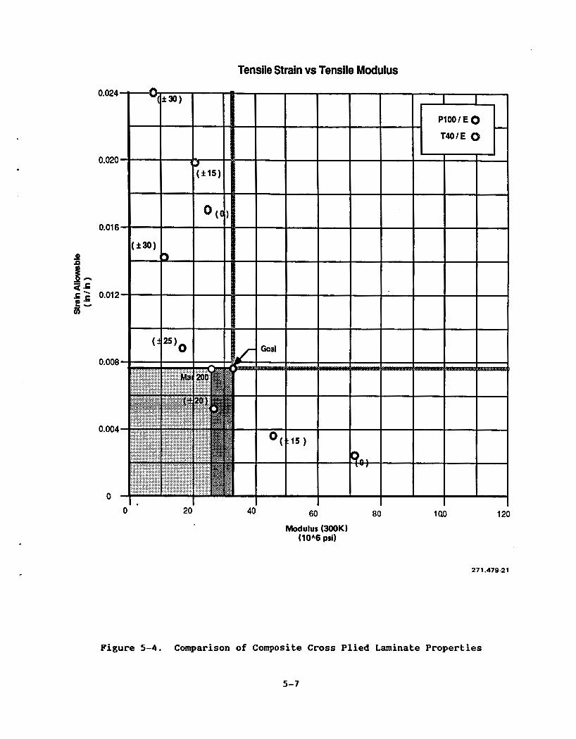
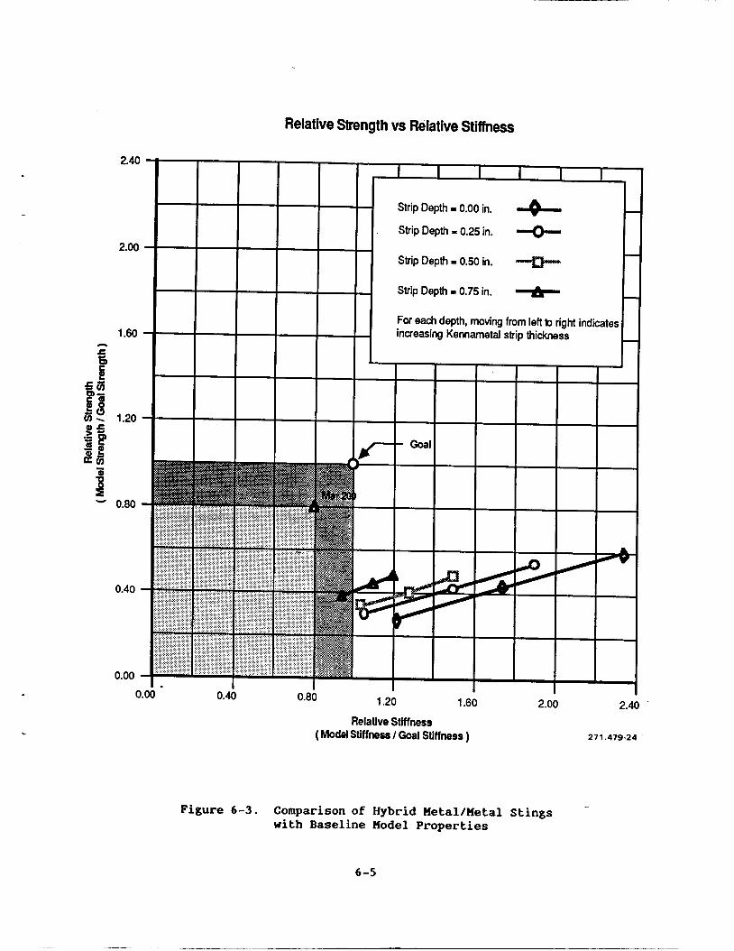
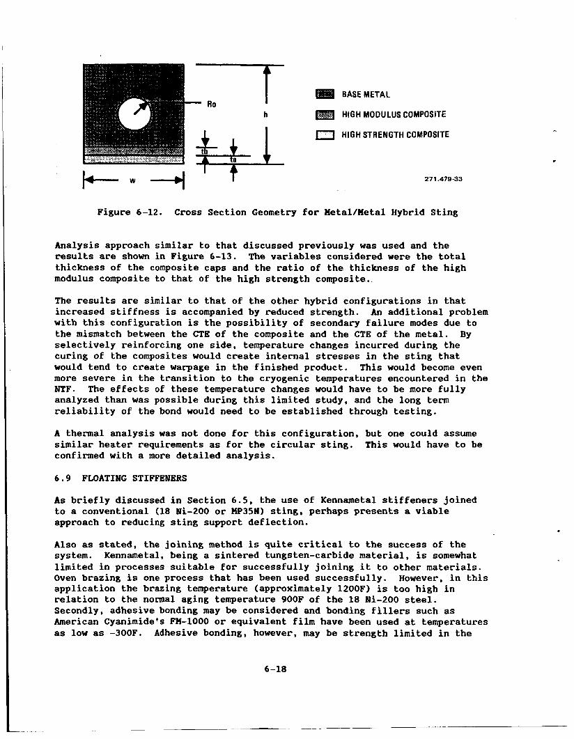
A rectangular cross section sting configuration incorporating reinforcing strips of ultra high modulus Kennametal was examined to determine its bending strength and stiffness properties. 6-2. The analysis approach was similar to that used with the circular metal/composite configuration with appropriate modifications used for generating section properties in the transition from a circular to a square section. These formulas were incorporated into a spreadsheet format to allow trade studies to be performed quickly and reliably. The variables considered were the depth the outside edge of the sting to the start of the Kennametal strip and the thickness of the Kennametal strip. The material properties from Table 6-1 were used and the results are summarized in Figure 6-3.
The geometry considered is shown in Figure
t H
BASEMETAL
0 HIGH MODULUS METAL
k W + 271.479-23
Figure 6-2. Cross Section Geometry for Metal/Metal Hybrid Sting
6 -3
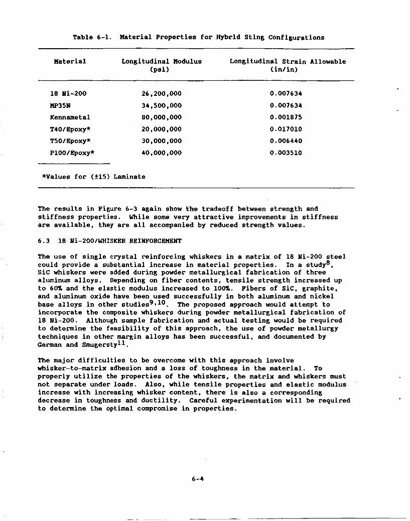
Table 6-1. Haterial Properties for Hybrid Sting Configurations
The results in Figure 6-3 again show the tradeoff between strength and stiffness properties. While some very attractive improvements in stiffness are available, they are all accompanied by reduced strength values.
6.3 18 Ni-200/WHISKER REINFORCEKENT
The use of single crystal reinforcing whiskers in a matrix of 18 Ni-200 steel could provide a substantial increase in material properties. Sic whiskers were added during powder metallurgical fabrication of three aluminum alloys. Depending on fiber contents, tensile strength increased up to 60% and the elastic modulus increased to 100%. and aluminum oxide have been used successfully in both aluminum and nickel base alloys in other studiesg*lO. incorporate the composite whiskers during powder metallurgical fabrication of 18 Ni-200. Although sample fabrication and actual testing would be required to determine the feasibility of this approach, the use of powder metallurgy techniques in other margin alloys has been successful, and documented by German and Smugerstyll.
In a study8,
Fibers of Sic, graphite,
The proposed approach would attempt to
The major difficulties to be overcome with this approach involve whisker-to-matrix adhesion and a loss of toughness in the material. To properly utilize the properties of the whiskers, the matrix and whiskers must not separate under loads. Also, while tensile properties and elastic modulus increase with increasing whisker content, there is also a corresponding decrease in toughness and ductility. Careful experimentation will be required t o determine the optimal compromise in properties.
'
6 -4
Relative Strength vs Relative Stiffness
2.40
2.00
1.60 n .e 5
gs -=p 88 sa, - - 0.80
0.40
0.00
I I I I I I _
Strip Depth = 0.00 in. 3- - Strip Depth = 0.25 in.
Strip Depth = 0.50 in.
4 -
I
1.20 1.60 2.00 2.40 0.00 0.40 0.80
Relative Stiffness ( Model Stiffness I Goal Stiffness ) 27 1.479-24
Figure 6-3. Comparison of Hybrid Metal/Metal Stings ~
with Baseline Model Properties
6-5
Current examples of material systems that have taken this approach to increasing stiffness are the graphite/epoxies, boron/aluminums, and carbon/carbon composites. Theoretically, the stiffness of these composftes should follow a law of mixtures relationship as follows:
I
I Using this relationship for example you would need only 15 volume percent Of tungsten filaments to increase the stiffness of 18 11-200 from 27 Hsi to 32 Hsi, a 20% increase in elastic modulus.
I 6.4 CLADDING
Cladding is the deposition of a layer of one metallic alloy on a substrate of a second alloy. surface of the substrate and the cladding material, which is introduced as a powder, wire, or thin sheet. Thus, when solidification occurs, a layer of cladding material is deposited with a small region of dilution giving a metallurgical bond. A clad component offers the designer flexibility since it permits combining the properties of two alloys. For this study we reviewed the feasibility of adding a cap of high stiffness material to a conventional sting of high strength but relatively low stiffness. Laser cladding produces homogenous microstructures on metal surfaces. By adding metal powders to the beam work surface, a smooth clad layer can be provided in many shapes and thicknesses. post-cladding machining can be accomplished.
The laser beam is used to melt both a thin layer on the
The variety of cladding materials available is extensive and
Present day examples of cladding are Inconel 625 over mild steel, and stellite over steel. Inconel 625 was clad on steel substrates by introducing a powder into the focused laser beam with motion controlled by robotic workstation. The Inconel overlay showed very little dilution into the base steel. Successful bend tests and dye penetrant tests were achieved. Deposition rates are about twice the rates achieved by conventional processing. Less heat is introduced so that less distortion is measured after processing.
For the sting application we reviewed cladding a tungsten alloy to 18 Ni-200, using the laser beam process. inch, and it is preferable to do this to a rectangular rather than a round bar. For comparison, therefore, assume:
Stellite has been clad to a thickness of 0.25 I
a. A bar 3 inches deep by 2 inches wide of 18 Ni-200.
b. A bar 2.5 inches deep by 2 inches wide of 18 Ni-200 with .25-inch tungsten caps added top and bottom.
To compare the relative strengthlstiffness of section a. and section b., assume values of:
18 Ni-200- Ptu - 200 ksi and E = 26 x lo6 psi
, Tungsten Ftu - 100 ksi and E = 59 x 106 psi
6 -6
The concept is equivalent to the metal/metal hybrids shown in Figures 6-2 and 6-3. In Figure 6-3 the strip depth would be 0.00 inch. As stated, as you move from left to right the Kennametal thickness is increasing, with the result that increasing stiffness is accompanied by decreased strength.
It should be recognized that cladding a metallic alloy on a second alloy will require some development work, and that all alloys are not suitable for cladding.
6.5 KENblAHETAL STING
Kennametal is a sintered tungsten-carbide material. elasticity, moderate strength, but a low Cvn impact resistance.
It has a high modulus of
In relation to this study, Kennametal's high modulus (94 Hsi) is its primary asset, while its low Cvn impact strength (Cvn toughness) is perhaps its primary l i a b i l i t y .
Previous study work discounted Kennametal as possible sting material largely on its low Cvn value. Since the completion of that studyl, a further review of the material, its properties, and vendor advances in its production, was made. Recent research indicated that certain grades of the material have been used in cryogenic applications as ultra high-stiffness tooling bars.
Kennametal Grade K9 is a possible candidate sting material; its major proper ties are: 1) strength; tensile 146 ksi, compression 590 ksi, 2) coefficient of thermal exoansion. 2.0 x in/in/deg F, 3) modulus, 83.5 x lo6 psi.
In reviewing the above data, it can be seen that the Cvn impact continues to be the restricting property of the material. However, Kennametal Incorporated indicates that their manufacturing processes are being further developed continually and therefore some improvement in this area may be feasible.
In addition to the limited Cvn impact strength, there are two areas in the manufacturing process.es that do not presently meet requirements. Currently, lengths of 2 to 3 feet are the maximum length available of the desired diameter of 1-1/2 to 2 inches. However, at larger diameters (3 to 4 inches), it may be feasible to sinter 4-fOOt length.
Conceptually, it appears that using Kennametal as a stiffener joined to a conventional material is perhaps a more viable alternative to the single homogeneous Kennametal concept presented above. This concept has the problem of matching stiffnesses to effect an optimum system stiffness that meets the design requirements. There is also the problem of joining the Kennametal to the parent material. There are three techniques that may be considered: oven brazing, adhesive bonding, and mechanical fastening. These will be further discussed in Section 6.9.
6-7
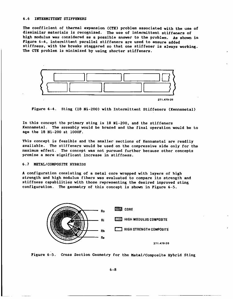
6.6 IblTERHITTENT STIFFENERS
The coefficient of thermal expansion (CTE) problem associated with the use of dissimilar materials is recognized. The use of intermittent stiffeners of high modulus was considered as a possible answer to the problem. As shown in Figure 6-4, intermittent parallel stiffeners are used to ensure added stiffness, with the breaks staggered so that one stiffener is always working. The CTB problem is minimized by using shorter stiffeners.
tuIIu 27 1.479-26
Figure 6-4. Sting (18 Mi-200) with Intermittent Stiffeners (Kennametal)
In this concept the primary sting is 18 Ni-200, and the stiffeners Kennametal. age the 18 Ni-200 at 1000F.
The assembly would be brazed and the final operation would be to
This concept is feasible and the smaller sections of Kennametal are readily available. maximum effect. The concept was not pursued further because other concepts promise a more significant increase in stiffness.
The stiffeners would be used on the compressive side only for the
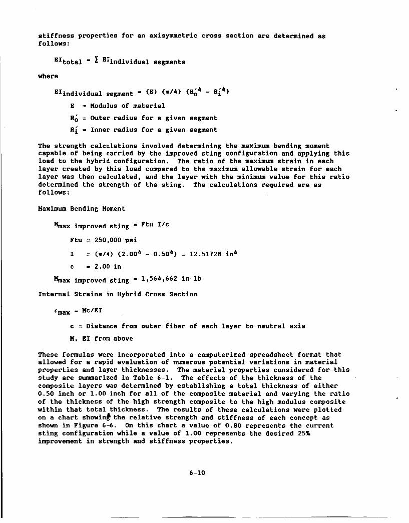
6.7 HBTAL/COHPOSITE HYBRIDS
A configuration consisting of a metal core wrapped with layers of high strength and high modulus fibers was evaluated to compare its strength and stiffness capabilities with those representing the desired improved sting configuration. The geometry of this concept is shown in Figure 6-5.
W
Ro
Ri
Rb
Ra
CORE
HIGH MODULUS COMPOSITE
HIGH STRENGTH COMPOSITE
271.479-26
Figure 6-5. Cross Section Geometry for the Hetal/Composite Hybrid Sting
6 -8
This concept offered the following advantages:
a. The metal core could be used to carry the shear and transverse load acting on the sting, allowing the composite materials to be highly oriented in the axial direction.
b. The high strength composite could be used as the outer layer, where it would be capable of carrying the higher strains resulting at that location.
c. The high modulus composite could be placed at an intermediate location, where it would be more isolated from high strain levels.
d. The composite materials are relatively insensitive to fatigue damage, and when damage does occur it results in a gradual degradation in strength and stiffness properties rather than the sudden, catastrophic failure that is associated with thick, high strength metallic materials.
e. The failure modes of the composite and metallic materials are uncoupled. A crack staring in the composite material is unlikely to propagate across the boundary into the metal core.
The disadvantages associated with this concept are:
a.
b.
C.
d.
The mismatch in the CTE for the different materials. considered for this application would have CTEs of approximately -1.00 x
in/in/deg F while the metal would have a CTE of approximately 5.00 x in/in/deg F.
The composites
Under the thermal cycling experienced by the sting, the long term reliability of the bond between the metal and composite is suspect and would have to be established through more detailed analysis than was possible during this initial investigation and would have to be demonstrated through testing.
The compressive strength of the high modulus composite material is questionable.
Stiffness can be achieved, but with significant loss of strength.
These disadvantages are discussed in detail in the following analysis.
The analysis approach taken to establish the performance of metal/composite hybrid configurations was to calculate the strength and stiffness properties of a cross section at the aft end of the sting and compare those results with the values for the baseline and improved sting configurations calculated earlier.
The critical values were assumed to be the bending stiffness at this section represented by the E1 term and the bending strength as determined by the maximum bending moment capable of being carried by the section. The bending
6 -9
stiffness properties for an axismetric cross section are determined as follows:
E1total = 2 "individual segments
where
EIindividual segment = (E) ( * I 4 1 ( R i 4 - R i 4 ) E = Modulus of material
R& = Outer radius for a given segment
Ri = Inner radius for a given segment
The strength calculations involved determining the maximum bending moment capable of being carried by the improved sting configuration and applying this load to the hybrid configuration. The ratio of the maximum strain in each layer created by this load compared to the maximum allowable strain for each layer was then calculated, and the layer with the minimum value for this ratio determined the strength of the sting. f 01 lows :
The calculations required are as
Maximum Bending Moment
h a x improved sting = Ftu
Ftu = 250,000 psi
I = ( ~ 1 4 ) (2.004 - 0.504) = 12.51728 in4
c = 2.00 in
&ax improved sting = 1,564,662 in-lb
Internal Strains in Hybrid Cross Section
tmax = Mc/EI
c = Distance from outer fiber of each layer to neutral axis
M, E1 from above
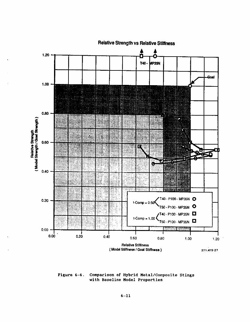
These formulas were incorporated into a computerized spreadsheet format that allowed for a rapid evaluation of numerous potential variations in material properties and layer thicknesses. study are summarized in Table 6-1. The effects of the thickness of the composite layers was determined by establishing a total thickness of either 0.50 inch or 1.00 inch for all of the composite material and varying the ratio of the thickness of the high strength composite to the high modulus composite within that total thickness. The results of these calculations were plotted on a chart showinb the relative strength and stiffness of each concept as shown in Figure 6-6. sting configuration while a value of 1.00 represents the desired 25% improvement in strength and stiffness properties.
The material properties considered for this
On this chart a value of 0.80 represents the current
6-10
1.20
1 .oo
0.80 n a
11 0.60
- 'i - 8
B - 0.40
0.20
0.00
Relative Strength vs Relative Stiffness
I
I
0.60 0.8Q 1 .oo 1.20 ' 0.00 0.20 0.40
Relative Stiffness ( Model Stiffness I Goal Stiffness ) 271.479-27
Figure 6-6. Comparison of Hybrid Metal/Composite Stings with Baseline Model Properties
6-11
The most notable result shown in Figure 6-6 is the tradeoff in stiffness and strength properties. TO achieve the stiffness values desired, significant losses in strength are incurred. One factor that is not accounted for in the data shown is the difference between the tensile and compressive strengths of the composite materials. reliable data on the compressive strengths of the high modulus composites was not available. generating the results. If the actual compressive strengths were considered, the relative strength values for these configurations would be less than half of those shown on this chart. When the data became available indicating that the compressive performance of these materials was poor, the concept was discarded from further consideration. The results are included for the sake of completeness and to show general trends in the behavior of this type of configuration if more acceptable materials become available.
When these calculations were initially performed,
As a result, only the tensile strengths were considered in
Recognizing the problem of the difference in CTE between the two materials, and the reliability of the bond at cryogenic temperatures, it was decided to investigate the feasibility of heating the bond line. The objective was to maintain the bond line at -100 to OF, as this condition would allow the use of a number of high quality adhesives. Controlling the temperature at the bond line causes a gradient across the composite material (possibly 0 to -300F), and possible thermal stress problems. This should not be a significant problem because of the low CTE (-1.00 x in/in/deg F).
6.8 SUHHARY OF THERMAL ANALYSIS
A thermal analysis of a cryogenic wind tunnel cylindrical sting has been completed. The proposed sting consists of a hollow metal core cylinder wrapped with graphite epoxy as shown in Figure 6-7. During a wind tunnel test the sting is subjected to operational temperature as low as -300F with resulting high heat transfer coefficients, thereby inducing thermal stresses.
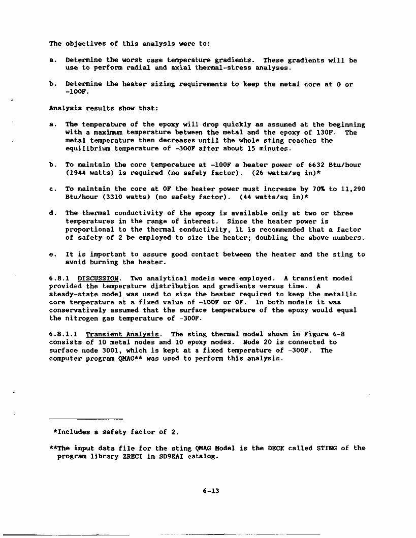
a. Determine the worst case temperature gradients. use to perform radial and axial thermal-stress analyses.
These gradients will be
b. Determine the heater sizing requirements to keep the metal core at 0 or -100F.
Analysis results show that:
a. The temperature of the epoxy will drop quickly as assumed at the beginning with a maximum temperature between the metal and the epoxy of 130F. metal temperature then decreases until the whole sting reaches the equilibrium temperature of -300F after about 15 minutes.
The
b. To maintain the core temperature at -100F a heater power of 6632 Btu/hour (1944 watts) is required (no safety factor). (26 watts/sq in)*
c. To maintain the core at OF the heater power must increase by 70% to 11,290 Btu/hour (3310 watts) (no safety factor). (44 wattslsq in)*
d. The thermal conductivity of the epoxy is available only at two or three temperatures in the range of interest. Since the heater power is proportional to the thermal conductivity, it is recommended that a factor of safety of 2 be employed to size the heater; doubling the above numbers.
e. It is important to assure good contact between the heater and the sting to avoid burning the heater.
6.8.1 DISCUSSION. Two analytical models were employed. A transient model provided the temperature distribution and gradients versus time. A steady-state model was used to size the heater required to keep the metallic core temperature at a fixed value of -100F or OF. In both models it was conservatively assumed that the surface temperature of the epoxy would equal the nitrogen gas temperature of -300F.
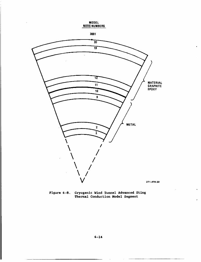
6.8.1.1 Transient Analysis. The sting thermal model shown in Figure 6-8 consists of 10 metal nodes and 10 epoxy nodes. surface node 3001, which is kept at a fixed temperature of -300F. The computer program QMAG** was used to perform this analysis.
Node 20 is connected to
*Includes a safety factor of 2.
**The input data file for the sting QMAG Model is the DECK called STIMG of the program library ZRECI in SD9BAI catalog.
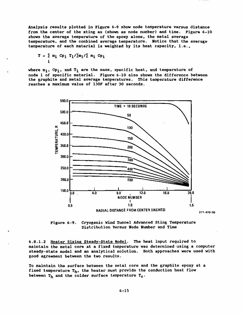
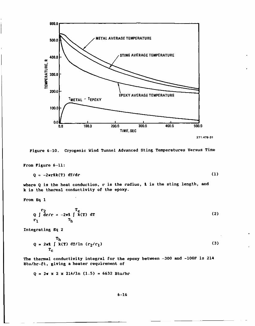
Analysis results plotted in Figure 6-9 show node temperature versus distance from the center of the sting as (shown as node number) and time. Figure 6-10 shows the average temperature of the epoxy alone, the metal average temperature, and the combined average temperature. Notice that the average temperature of each material is weighted by its heat capacity, i.e.,
where mi, Cpi, and Ti are the mass, specific heat, and temperature of node i of specific material. Figure 6-10 also shows the difference between the graphite and metal average temperatures. reaches a maximum value of 130F after 30 seconds.
This temperature difference
550.0
500.0
450.0 a wi a 3 400.0 I-
d z 350.0
I- 300.0
250.0
ZOO.[
150.0
7 TIME = 10SECONDS
I I I I
NODE NUMBER I
1.0 . 4.0 8.0 , 12.0 16.0 2 .O
0.5 1 .o 1.5 RADIAL DISTANCE F R O M CENTER (INCHES) 271.479-30
Figure 6-9. Cryogenic Wind Tunnel Advanced Sting Temperature Distribution Versus Node Number and Time
6.8.1.2 Heater Sizing Steady-State Model. The heat input required to maintain the metal core at a fixed temperature was determined using a computer steady-state model and an analytical solution. Both approaches were used with good agreement between the two results.
To maintain the surface between the metal core and the graphite epoxy at a fixed temperature Th, the heater must provide the conduction heat flow between Th and the colder surface temperature Tc.
6-15
6oo.o I
400.0 a wi a 3 I- 2 300.0 w p. B w I-
200.0
STING AVERAGE TEMPERATURE -
-
- EPOXY AVERAGE TEMPERATURE
I TMETAL - TEPOXY I
100.0 200.0 300.0 400.0 500.0 TIME, SEC
271 A79 8-31
Figure 6-10. Cryogenic Wind Tunnel Advanced Sting Temperatures Versus Time
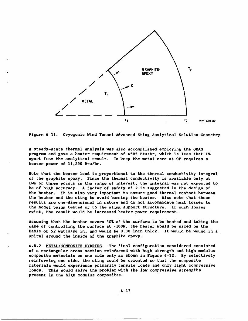
From Figure 6-11:
Q = -2srllk(T) dT/dr (1)
where Q is the heat conduction, r is the radius, ll is the sting length, and k is the thermal conductivity of the epoxy.
From Eq 1
r2 TC Q I dr/r = -2d k(T) dT =1 Th
(2)
Integrating Eq 2
Th Q = 2sll I k(T) dT/ln (r2/rl) (3 )
TC
The thermal conductivity integral for the epoxy between -300 and -100F is 214 Btu/hr-ft, giving a heater requirement of
A steady-state thermal analysis was also accomplished employing the QKAG program and gave a heater requirement of 6585 Btulhr, which is less that 1% apart from the analytical result. heater power of 11,290 Btu/hr.
To keep the metal core at OF requires a
Note that the heater load is proportional to the thermal conductivity integral of the graphite epoxy. Since the thermal conductivity is available only at two or three points in the range of interest, the integral was not expected to be of high accuracy. A factor of safety of 2 is suggested in the design of the heater. It is also very important to assure good thermal contact between the heater and the sfing to avoid burning the heater. Also note that these results are one-dimensional in nature and do not accommodate heat losses to the model being tested or to the sting support structure. If such losses exist, the result would be increased heater power requirement.
Assuming that the heater covers 50% of the surface to be heated and taking the case of controlling the surface at -100F, the heater would be sized on the basis of 52 watts/sq in, and would be 0.30 inch thick. It would be wound in a spiral around the inside of the graphite epoxy.
6.8.2 HETAL/COHPOSITE HYBRIDS. The final configuration considered consisted of a rectangular cross section reinforced with high strength and high modulus composite materials on one side only as shown in Figure 6-12. By selectively reinforcing one side, the sting could be oriented so that the composite materials would experience primarily tensile loads and only light compressive loads. This would solve the problem with the low compressive strengths present in the high modulus composites.
6-17
BASE METAL
HIGH MODULUS COMPOSITE
0 HIGH STRENGTH COMPOSITE
271.479-33
Figure 6-12. Cross Section Geometry for Metal/Hetal Hybrid Sting
Analysis approach similar to that discussed previously was used and the results are shown in Figure 6-13. The variables considered were the total thickness of the composite caps and the ratio of the thickness of the high modulus composite to that of the high strength composite..
The results are similar to that of the other hybrid configurations in that increased stiffness is accompanied by reduced strength. with this configuration is the possibility of secondary failure modes due to the mismatch between the CTE of the composite and the CTE of the metal. By selectively reinforcing one side, temperature changes incurred during the curing of the composites would create internal stresses in the sting that would tend to create warpage in the finished product. This would become even more severe in the transition to the cryogenic temperatures encountered in the NTF. The effects of these temperature changes would have to be more fully analyzed than was possible during this limited study, and the long term reliability of the bond would need to be established through testing.
An additional problem
A thermal analysis was not done for this configuration, but one could assume similar heater requirements as for the circular sting. This would have to be confirmed with a more detailed analysis.
6.9 FLOATING STIFFENERS
As briefly discussed in Section 6.5, the use of Kennametal stiffeners joined to a conventional (18 Ni-200 or wP35N) sting, perhaps presents a viable approach to reducing sting support deflection.
Also as stated, the joining method is quite critical to the success of the system. Kennametal, being a sintered tungsten-carbide material, is somewhat limited in processes suitable for successfully joining it to other materials. Oven brazing is one process that has been used successfully. application the brazing temperature (approximately 1200F) is too high in relation to the normal aging temperature 900F of the 18 Ni-200 steel. Secondly, adhesive bonding may be considered and bonding fillers such as American Cyanimide's FH-1000 or equivalent film have been used at temperatures as low as -300F. Adhesive bonding, however, may be strength limited in the
However, in this
6-18
Relative Strength vs Relative Stiffness
1.20
1 .oo
0.80
0.60
0.40
0.20
0.00
0.40 0.60 0.80 1 .oo 1 .z 0.00 0.20
Relative Stiffness (Model Stiffness I Goal Stiffness )
I
271.479-34
Figure 6-13. Comparison of Hybrid Hetal/Composite Stings with Baseline Hodel Properties
6-19
shear directions of the bond system. differential CTEs of the materials.
The limitation is due primarily to the
1-25 FEET-1
Mechanical fastening also offers an approach to joining the materials considered. In this application, a close sliding fit of the mating diameters is required at the forward end of the sting. At the aft end, a tapered joint secured by bolts may provide the "fixity" between the mating parts. sting is deflected and/or subjected to temperature, the parts will have "relative freedom" to move in the axial direction.
As the
Two design concepts using sliding stiffeners have been considered. employs a concentric inner rod made of Kennametal. Mi-200 or equivalent steel as shown in Figure 6-14.
The first The outer member is of 18
FLOATING STIFFENER CONCEPT
2 112 - 3 DIA. ,FREE SLIDING ,LOCKED TAPER JOINT
Engineering analyses will be required to optimized the stiffness-to-strength ratio of the system, while minimizing temperature effects due to CTE differentials.
The concept employs conventional manufacturing and materials processes that should facilitate the production of hardware.
The second concept considered locates the stiffer Kennametal sliding member eccentrically to the centerline of the system. The Kennametal is located on the compressive side due to its high compressive strength. designed into the system will minimize the CTE problem.
The sliding motion
6-20
To investigate the concept, a test specimen was fabricated using existing materials. A beam of rectangular cross section was grooved on its compressive side along the upper centerline, as shown in Figure 6-15. Two rods (one steel and one Kennametal) were fitted to the groove to provide "fixity" at one end, while sliding along its length.
ARE INCHES 271 A79-36
Figure 6-15. Proof of Concept, Floating Stiffener
Deflection tests were conducted in the following sequence:
1. Beam without a stiffener
2. Beam with a steel stiffener
3. Beam with a Kennametal stiffener
The results are show in Figure 6-16. The Kennametal stiffener shows a definite improvement in the reduction of deflection for a given load, thereby indicating an improvement in the stiffness-to-strength ratio. Further development in this area is required to fully substantiate the viability of this concept.
6-21
U tOAD (pounds) 271.479-37
6-16. Experiment - Floating Stiffener - Deflection Versus Load
SECTION 7
CANDIDATES FOR PROOF-OF-CONCEPT TESTS
In this study the use of advanced materials for high performance stings was investigated. In doing so three separate areas were reviewed:
Conventional Metals Advanced Composites
0 Hybrid Configurations
The objective of increasing the values of the ultimate tensile strength, and the modulus, E, of 18 Eli-200 by 25%, while maintaining toughness values, is not an easy task. An innovative approach is required.
For conventional metals, the research was directed toward the multiphase superalloys. Advanced composites, while promising as fibers, have limitations in laminate form particularly when a combination of high strength and high stiffness is required. Hybrids look promising, but the use of dissimilar materials, and the subsequent thermal stress problems due to differences in the coefficient of expansion, raises question with respect to the integrity of the design.
This study has identified a number of concepts that appear promising, yet are questionable because **it hasn't been done before.** To achieve our objective, it becomes necessary to select the candidates with the best chance of success, and to further develop those concepts by building hardware, and to subject each design to proof-of-concept tests under environmental condition.
The recommended configurations are:
1. HP35N - laserweld/diffusion weld 2.
3. 18 Ni-200 with a Kennametal floating stiffener
18 Mi-200 with a high modulus composite strip on the tension side
In configurations 1 and 2, the proposed test article is a constant cross-section 3 inches by 2 inches wide and 2 feet long. Configuration 3 is 2-1/2 inches in diameter by 2 feet long with a Kennametal insert.
7-1
SECTION 8
COMCLUSIONS
0 There is no simple solution. will require further development of the manufacturing process.
Each of the concepts described in this report
0 Proof-of-concept tests are necessary, and must be done under cryogenic conditions.
0 Advanced composites, particularly the ultra-high modulus graphite laminates are unpredictable when loaded in compression.
Hybrid concepts appear to be promising if the differences in CTE can be overcome. Some past tests have shown that CTE problems, while expected, did not occur. Proof-of-concept tests will verify this.
0 Vendor/expert response to questions, usually are: "It's impossible," or "It's no problem." The real answer is in between.
0 Some superalloys are candidates but are very limited in available sizes; building them into the desired shapedsizes will require fabrication process development. if there is sufficient demand.
In the long term, the mill will produce larger sizes,
0 In hybrid concepts, the adhesives available are suspect at cryogenic temperatures. It is possible to heat the bond line; however, this could introduce temperature to the balance and create an undesirable gradient.
The superalloys are cold worked to obtain a high ultimate tensile stress, and modulus, E. If they subsequently are subjected to temperatures in excess of 1000F, they lose those properties.
The cost of superalloys such as W35N is high - $50 to $100/lb.
The high performance sting would be approximately 5 to 6 feet long, and adapted into an existing sting. The taper joint between the balance/conventional sting and the high performance sting must also be evaluated.
A fail-safe feature in the sting is desirable.
8-1
SECTION 9
REFERENCES
1. S. A. G r i f f i n , D. S. Madsen, and A. A. McClain, Design Study o f Test Models of Maneuvering A i r c r a f t Conf igurat ions f o r the Nat ional Transonic F a c i l i t y , NASA C on t rac t Report 3uil/ , August 1984.
2. Wind Tunnel Model Systems C r i t e r i a, LHB 1710.15, NASA Langl ey Research Center, August 1986.
3. Technical Report - MP35N, Latrobe Steel Co., Latrobe, PA 15650, Report No. 56081, September 1983.
4. R. L. Tobler, Ma te r ia l s fo r Cryogenic Wind Tunnel Testing, NBSIR 79-1624, May 1-980.
5. K. B. Meyer, Fab r i ca t i on of a High Strength Tube by S p i r a l Winding, GDC-MRR-80-004, December 1980.
6. A3.0-80, American Welding Society, August 1979.
7. Advanced Composite Systems, Union Carbide Corporation Data Sheet - ACS, Chicago, I L 60606, 1986.
8. D. L. McDaniels, Analys is o f Stress-Strain, Fracture, and D u c t i l i t y Behavior o f Aluminum Mat r ix Composites Containing Discontinuous Si1 i con Carb i de Reinforcement, NASA L ewi s Research Center, C1 eve1 and, OH, NASA TM83610, March 1984.
9. P. J. Mazzei, G. Vandrmen. and M. J. Hakins. Powder Fabr i ca t i on o f F i ber-Rei n forced Superal l oy Turbi ne 61 ades , ~ W m i s e Canada L imi ted, Turb ine and Generator D iv is ion , Hamil ton, Ontario, Canada, November, 1976.
10. D. Webster, "Proper t ies and Mic ros t ruc ture of Metal Ma t r i x Composites ," Advances i n Composite Mater ia ls , Proceedings o f the T h i r d I n t e r n a t i o n a l 'Conterence o f Composite Mater31 s , Par is , France, Vol . 2, Pergamon Press, Oxford, 1980, pp. 1165-1176, August, 1980.
11. J. E. Smugersty and R. M. Gesman, "Hot I s o s t a t i c Pressing o f Maraging Stee ls ,'I National Powder Metal1 urgy Conference 7th-8th, pp. 69-82, 1978-1979 Proceedings.
9- 1
Standard Bibliographic Page
NASA CR- 1782 14 I. Title and Subtitle
Design Study o f Advanced Model Support Systems f o r the Nat ional Transonic F a c i l i t y
L . Report No. 12. Government Accession No. 13. Recipient's Catalog No.
5. Report Date
J~~~~~~ 1987 6. Performing Organization Code
T . Author(s)
3. Performing Organization Name and Address General Dynamics Convai r D i v i s ion P. 0. Box 85337 San Diego, CA 92138
12. Sponsoring Agency Name and Address
Was h i ng ton, D. C . 20546 Nat ional Aeronautics and Space Admi n i s t r a t i on
8. Performing Organization Report NO.
10. Work Unit No.
11 . Contract or Grant No.
, P.0- L-99725B 13. Type of Report and Period Covered
19. Security Classif. of this report) Uncl ass i f i e 6
~~ ~
15. Supplementary Notes Langley Technical Monitor: D r . C. P. Young, Jr. Use o f trademarks o r names o f manufacturers i n t h i s r e p o r t does n o t c o n s t i t u t e an o f f i c i a l endorsement o f such products o r manufacturers, e i t h e r expressed o r implied, by t h e National Aeronautics and Space Admin is t ra t ion.
16. AbstraFt It has long been recognized t h a t t h e s t i n g ( o r support system) i s a very c r i t i c a l p a r t of t h e model system. The designer i s f requen t l y faced w i t h t h e t radeof f of min imiz ing s t i n g s ize, thereby compromising f a c i l i t y and model safety , against a l a rge r s t i n g and the subsequent problems o f s t i n g in te r fe rence effects. In the NASA Langley Research Center National Transonic F a c i l i t y (NTF), t h i s problem i s accentuated by t h e severe environment o f high pressure/low temperature, designed i n t o the f a c i l i t y t o p rov ide t h e desired h igh Reynolds number. Compromises i n t h e con f igu ra t i on geometry and/or l i m i t i n g the t e s t envelope are the re fo re con t ra ry t o the purposes and goals of the NTF and are unacceptable, hence t h e need f o r t h i s study of advanced model support systems. of an i nves t i ga t i on aimed a t improvements of 25 percent i n both s t rength and Young's modulus of . e l a s t i c i t y as compared t o h igh s t rength c ryogen ica l l y acceptable s tee ls c u r r e n t l y being used. of ma te r ia l s were s tud ied along w i th d i f f e r e n t design approaches. Design concepts were developed which inc luded conventional ma te r ia l s t i ngs , advanced composites, and h y b r i d conf igura t ions . i n d i c a t e t h a t s ign i f i can t improvements i n both s t rength and s t i f f n e s s are poss ib le and various promising design concepts are presented. con f igura t ions are recommended based on best chance o f success and proposed proof-of-concept t e s t s under environmental cond i t ions .
This paper documents the r e s u l t s
Various m a t e r i a l s o r combinations
Results o f t he study
Candidate
20. Security Classif.(of this page) 21. No. of Pages 22. Price Unc lass i f i ed 68 A04
17. Key Words (Suggested by Authors(s))
Wind Tunnel Model Support Cryogenic Tunnel s Cryogenic Mater ia ls
18. Distribution Statement
Unc lass i f i ed - Un l im i ted
Subject Category 09
For sale by the National Technical Information Service, Springfield, Virginia 22161