81
CONTROL AND AND PROTECTION

CONTROL AND AND
PROTECTION

Protection and Safety Interlocks

Protection – General understanding?
What we already know.
n Operation of the BOILER, TURBINE, GENERATOR are closely coupled
n A trip on any one of the three has a direct impact on the continued operation of the other two causing interruption to power production process
n Why Trip – On occurrence of any unsafe or abnormal operating condition the BOILER, TURBINE, GENERATOR are tripped individually
Protection – General understanding?
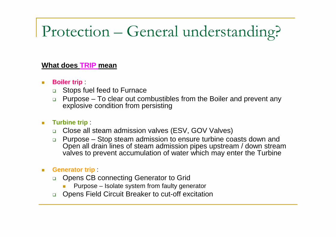
What does TRIP mean
n Boiler trip : q Stops fuel feed to Furnaceq Purpose – To clear out combustibles from the Boiler and prevent any
explosive condition from persisting
n Turbine trip : q Close all steam admission valves (ESV, GOV Valves)q Purpose – Stop steam admission to ensure turbine coasts down and
Open all drain lines of steam admission pipes upstream / down stream valves to prevent accumulation of water which may enter the Turbine
n Generator trip : q Opens CB connecting Generator to Grid
n Purpose – Isolate system from faulty generatorq Opens Field Circuit Breaker to cut-off excitation
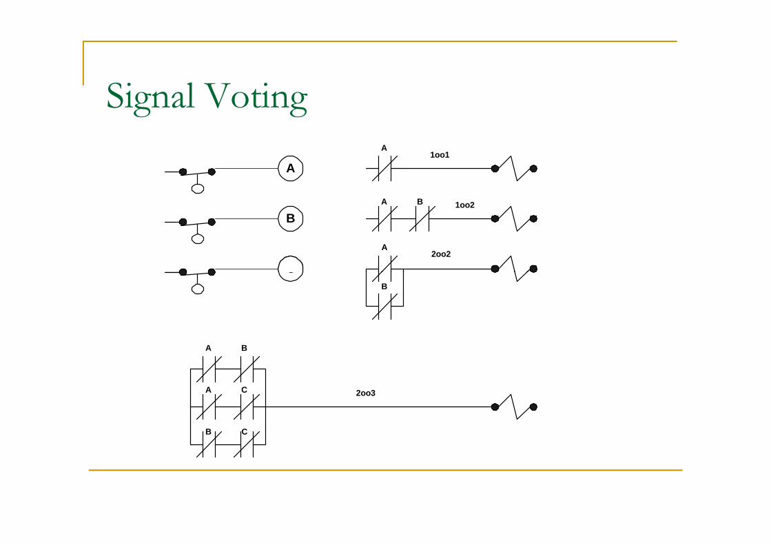
Signal Voting
A
B
C
A
A B
A
1oo1
1oo2
2oo2
CB
2oo3
A B
A C
B C
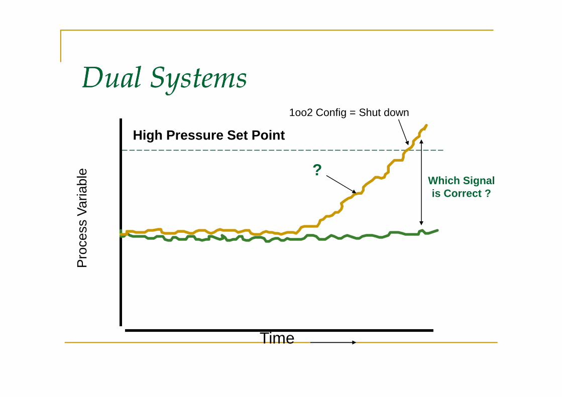
Dual SystemsDual SystemsP
roce
ss V
aria
ble
High Pressure Set Point
?Which Signalis Correct ?
1oo2 Config = Shut down
Time
Pro
cess
Var
iabl
e
is Correct ?
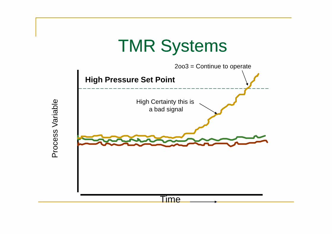
TMR SystemsTMR SystemsP
roce
ss V
aria
ble
High Pressure Set Point
2oo3 = Continue to operate
High Certainty this is a bad signal
Time
Pro
cess
Var
iabl
e

TMR SystemsTMR SystemsP
roce
ss V
aria
ble
High Pressure Set Point
2oo3 = Shut Down
High Certainty these are good signals
Time
Pro
cess
Var
iabl
e
High Certainty this is a BAD signal
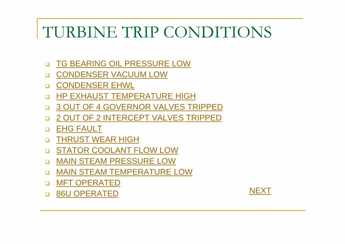
TURBINE TRIP CONDITIONS
q TG BEARING OIL PRESSURE LOWq CONDENSER VACUUM LOWq CONDENSER EHWLq HP EXHAUST TEMPERATURE HIGHq 3 OUT OF 4 GOVERNOR VALVES TRIPPEDq 2 OUT OF 2 INTERCEPT VALVES TRIPPED2 OUT OF 2 INTERCEPT VALVES TRIPPEDq EHG FAULTq THRUST WEAR HIGHq STATOR COOLANT FLOW LOWq MAIN STEAM PRESSURE LOWq MAIN STEAM TEMPERATURE LOWq MFT OPERATEDq 86U OPERATED NEXT
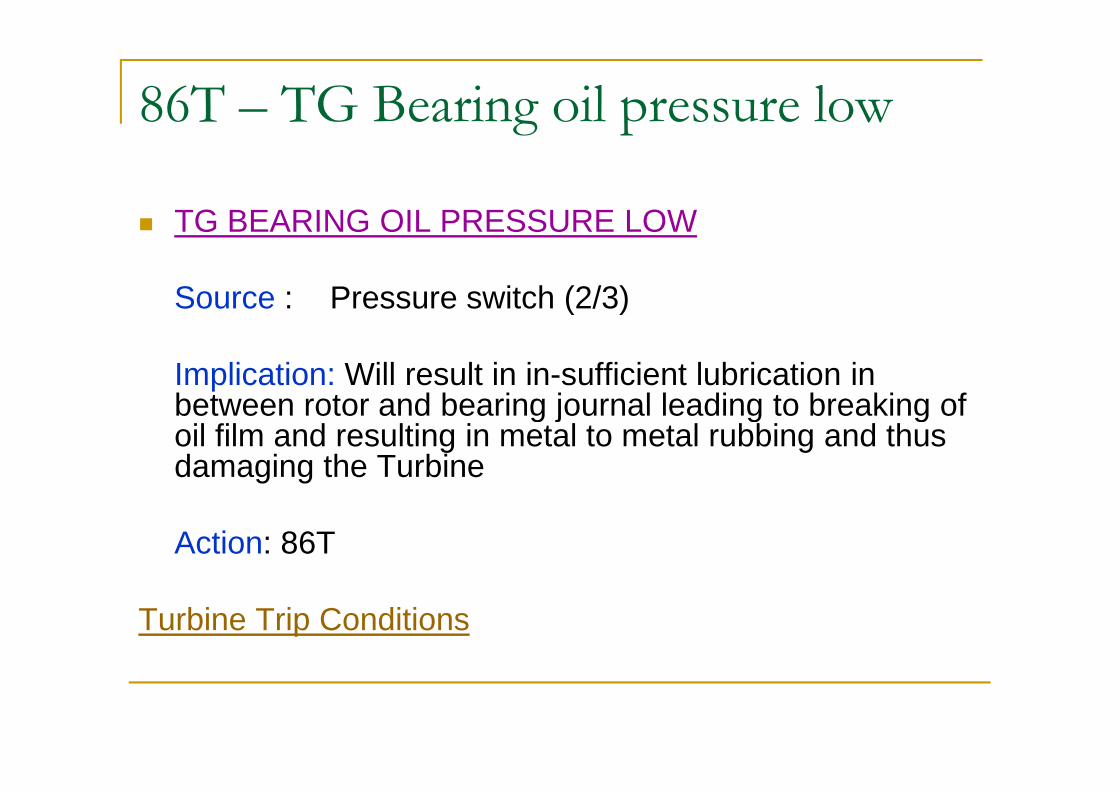
86T – TG Bearing oil pressure low
n TG BEARING OIL PRESSURE LOW
Source : Pressure switch (2/3)
Implication: Will result in in-sufficient lubrication in between rotor and bearing journal leading to breaking of between rotor and bearing journal leading to breaking of oil film and resulting in metal to metal rubbing and thus damaging the Turbine
Action: 86T
Turbine Trip Conditions

86T – Condenser Vacuum Low
n Condenser Vacuum Low
Source : Pressure Transmitter (2/3)….. EHG…..
Implication: Will produce undue stress on Turbine blades due to reduction of “available enthalpy” (rise in exhaust conditions). Usually reduction of “available enthalpy” (rise in exhaust conditions). Usually a Trip is preceded by “de-loading of turbine” as per Turbine manufacturer recommendation
Action: 86T
Turbine Trip Conditions
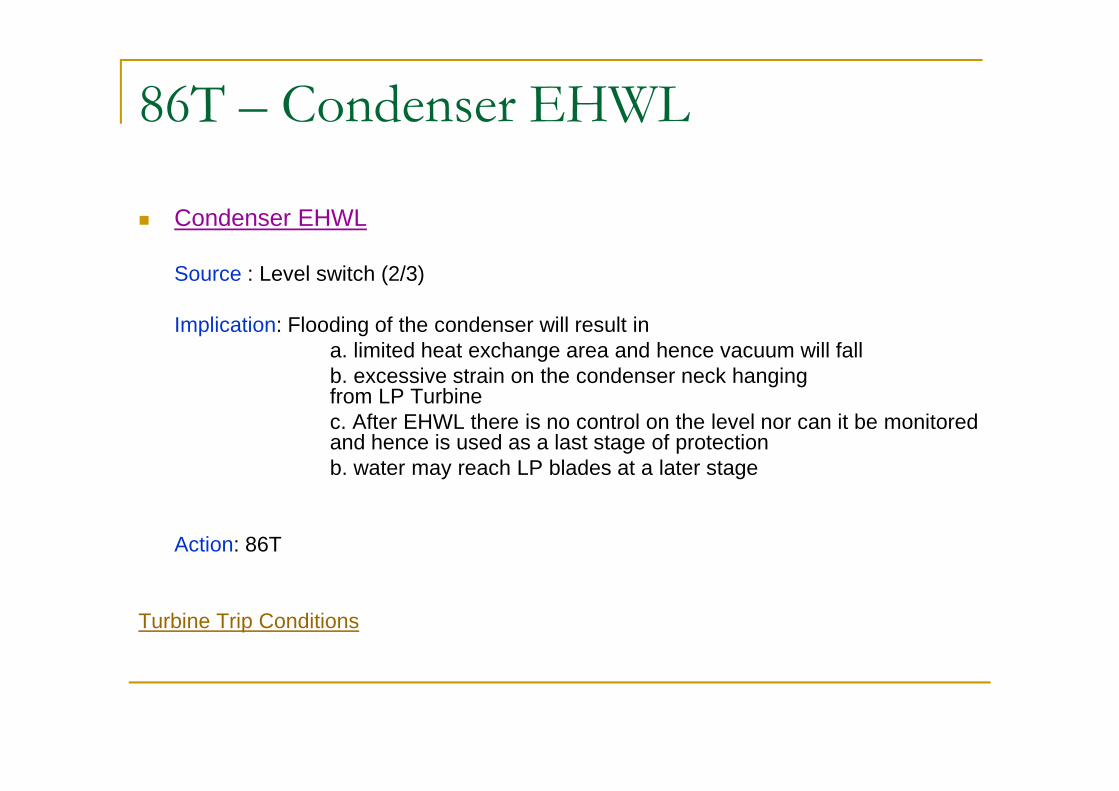
86T – Condenser EHWL
n Condenser EHWL
Source : Level switch (2/3)
Implication: Flooding of the condenser will result in a. limited heat exchange area and hence vacuum will fallb. excessive strain on the condenser neck hanging from LP Turbinefrom LP Turbinec. After EHWL there is no control on the level nor can it be monitored and hence is used as a last stage of protectionb. water may reach LP blades at a later stage
Action: 86T
Turbine Trip Conditions

86T – HP Exhaust Temperature High
n HP Exhaust Tempertaure High
Source : Thermocouple (2/3)…EHG ….
Implication: Deviation in “available enthalpy” across HP Turbine from design value will produce stress on HP blades . This is special from design value will produce stress on HP blades . This is special protection feature for Tubines equipped with HPLP Bypass.
Action: 86T
Turbine Trip Conditions
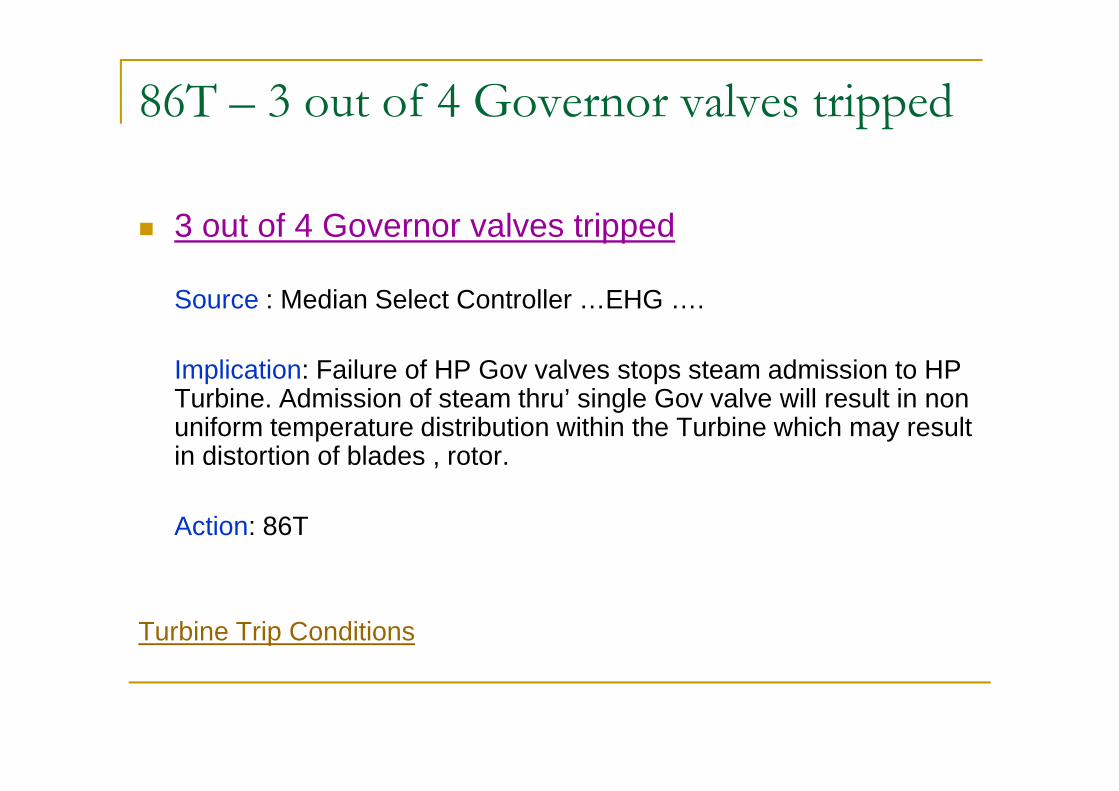
86T – 3 out of 4 Governor valves tripped
n 3 out of 4 Governor valves tripped
Source : Median Select Controller …EHG ….
Implication: Failure of HP Gov valves stops steam admission to HP Turbine. Admission of steam thru’ single Gov valve will result in non Turbine. Admission of steam thru’ single Gov valve will result in non uniform temperature distribution within the Turbine which may result in distortion of blades , rotor.
Action: 86T
Turbine Trip Conditions
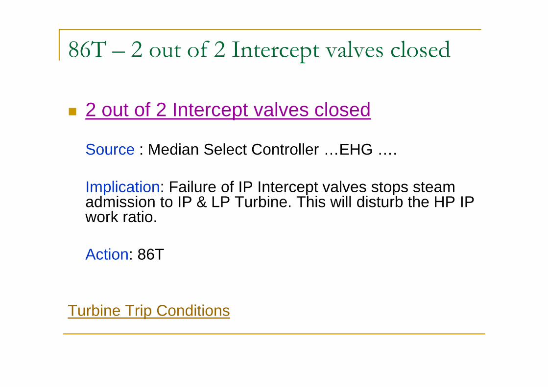
86T – 2 out of 2 Intercept valves closed
n 2 out of 2 Intercept valves closed
Source : Median Select Controller …EHG ….
Implication: Failure of IP Intercept valves stops steam admission to IP & LP Turbine. This will disturb the HP IP Implication: Failure of IP Intercept valves stops steam admission to IP & LP Turbine. This will disturb the HP IP work ratio.
Action: 86T
Turbine Trip Conditions
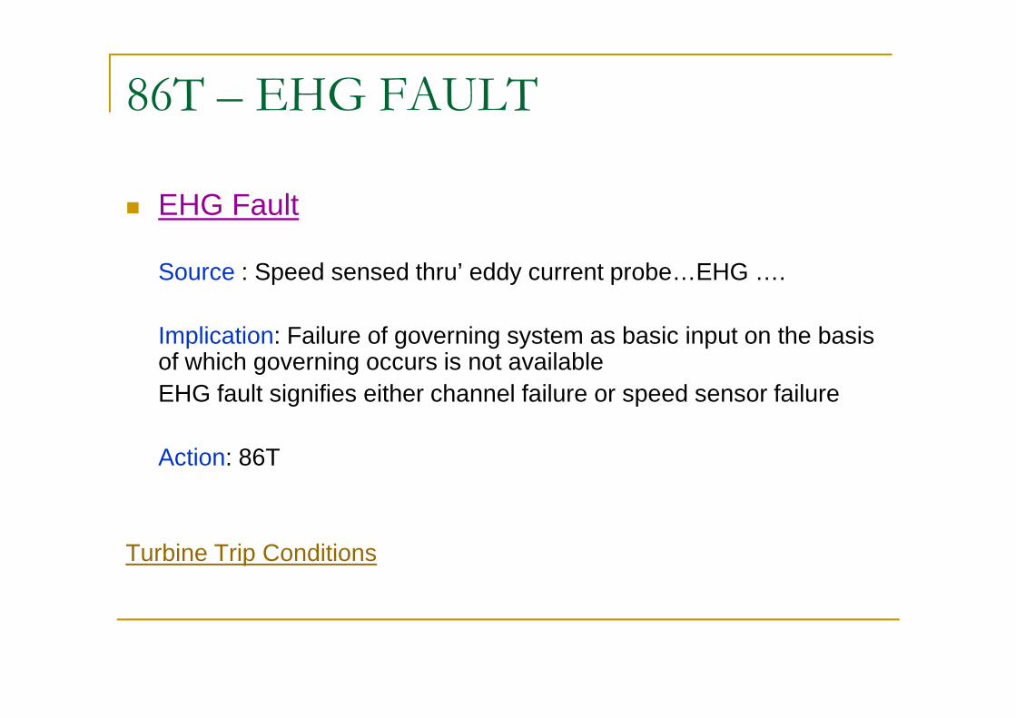
86T – EHG FAULT
n EHG Fault
Source : Speed sensed thru’ eddy current probe…EHG ….
Implication: Failure of governing system as basic input on the basis of which governing occurs is not availableof which governing occurs is not availableEHG fault signifies either channel failure or speed sensor failure
Action: 86T
Turbine Trip Conditions

86T – Thrust Wear High
n Thrust Wear High
Source : Eddy Current Probe…TSE ….
Implication: Indicates axial shift of rotor with respect to stator in the axial direction and may result in fixed and moving blades fouling . axial direction and may result in fixed and moving blades fouling . The reference point of rotor located with the stator will shift as a result of wear on the thrust pads / collar.
Action: 86T
Turbine Trip Conditions

86T – Stator Coolant Flow Low
n Stator Coolant Flow Low
Source : Flow switch (2/3) + timer….
Implication: Will result in heating up of the hollow conductors in generator as little or no cooling medium is present and lead to insulation failure. This has been purposely introduced under Turbine insulation failure. This has been purposely introduced under Turbine protection rather than generator protection due to implications in house load operation.
Action: 86T
Turbine Trip Conditions
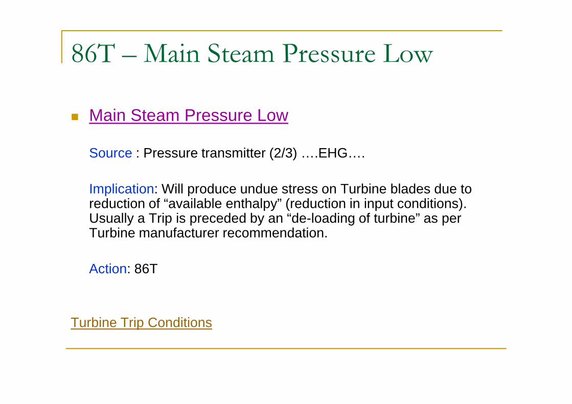
86T – Main Steam Pressure Low
n Main Steam Pressure Low
Source : Pressure transmitter (2/3) ….EHG….
Implication: Will produce undue stress on Turbine blades due to reduction of “available enthalpy” (reduction in input conditions). reduction of “available enthalpy” (reduction in input conditions). Usually a Trip is preceded by an “de-loading of turbine” as per Turbine manufacturer recommendation.
Action: 86T
Turbine Trip Conditions
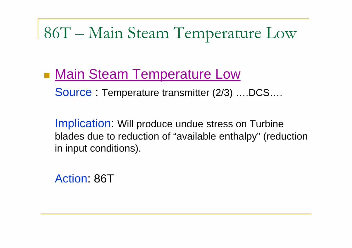
86T – Main Steam Temperature Low
n Main Steam Temperature LowSource : Temperature transmitter (2/3) ….DCS….
Implication: Will produce undue stress on Turbine Implication: Will produce undue stress on Turbine blades due to reduction of “available enthalpy” (reduction in input conditions).
Action: 86T

86T – Main Steam Temperature Low Logic
Turbine Trip Conditions
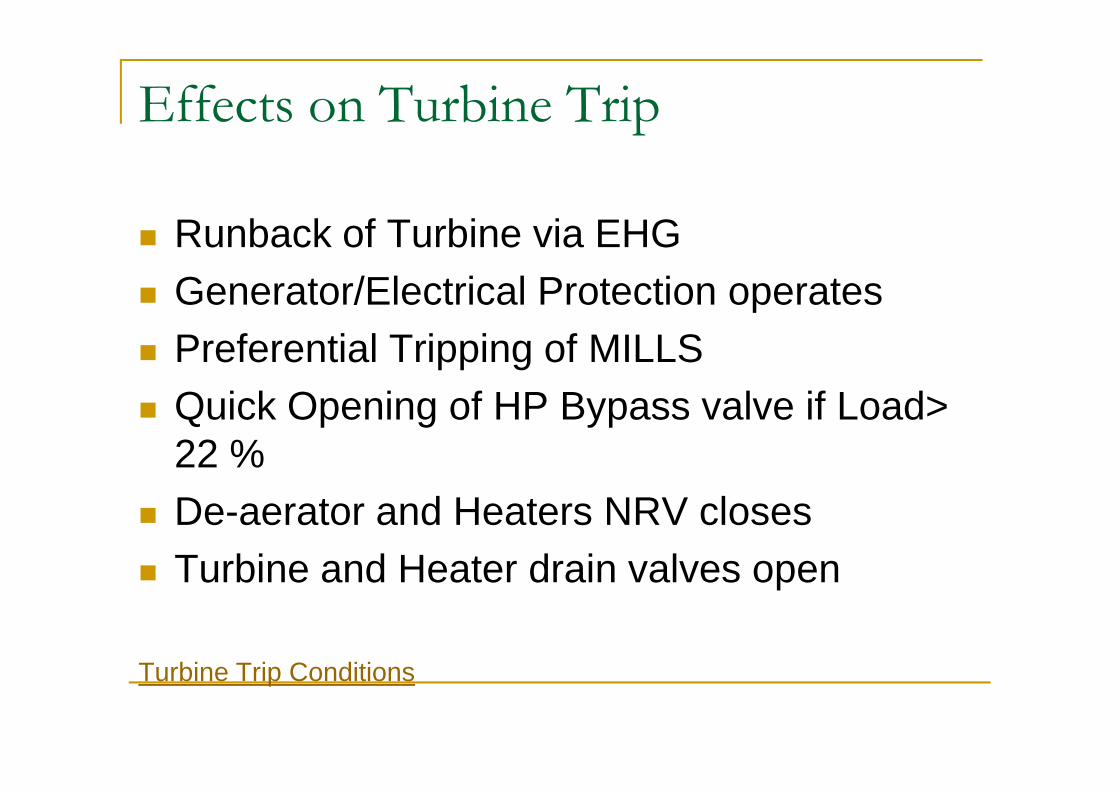
Effects on Turbine Trip
n Runback of Turbine via EHG
n Generator/Electrical Protection operates
n Preferential Tripping of MILLS
Quick Opening of HP Bypass valve if Load> n Quick Opening of HP Bypass valve if Load> 22 %
n De-aerator and Heaters NRV closes
n Turbine and Heater drain valves open
Turbine Trip Conditions
Boiler
ØProtection and Safety Interlocks
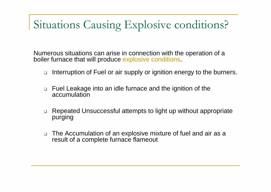
Situations Causing Explosive conditions?
Numerous situations can arise in connection with the operation of a boiler furnace that will produce explosive conditions.
q Interruption of Fuel or air supply or ignition energy to the burners.
q Fuel Leakage into an idle furnace and the ignition of the accumulation accumulation
q Repeated Unsuccessful attempts to light up without appropriate purging
q The Accumulation of an explosive mixture of fuel and air as a result of a complete furnace flameout
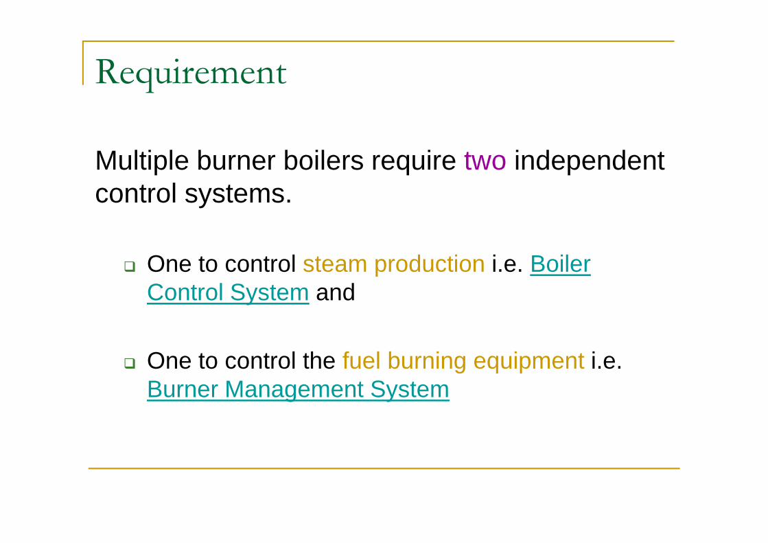
Requirement
Multiple burner boilers require two independent control systems.
q One to control steam production i.e. Boiler q One to control steam production i.e. Boiler Control System and
q One to control the fuel burning equipment i.e. Burner Management System
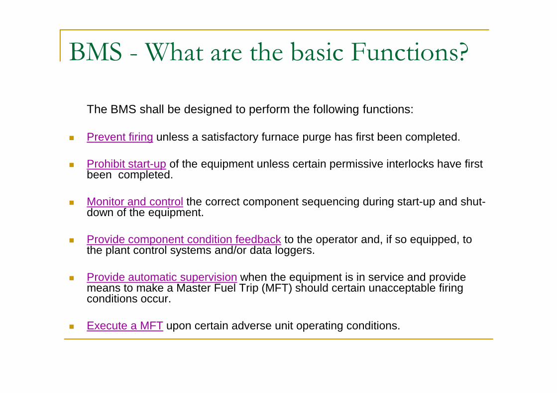
BMS - What are the basic Functions?
The BMS shall be designed to perform the following functions:
n Prevent firing unless a satisfactory furnace purge has first been completed.
n Prohibit start-up of the equipment unless certain permissive interlocks have first been completed.
Monitor and control the correct component sequencing during start-up and shut-n Monitor and control the correct component sequencing during start-up and shut-down of the equipment.
n Provide component condition feedback to the operator and, if so equipped, to the plant control systems and/or data loggers.
n Provide automatic supervision when the equipment is in service and provide means to make a Master Fuel Trip (MFT) should certain unacceptable firing conditions occur.
n Execute a MFT upon certain adverse unit operating conditions.

How do we categorize the different controls
A Boiler Control System shall have the following applications
n Combustion control
n Excess air control
n Steam drum level controln Steam drum level control
A Burner Management System shall have the following applications
n Boiler purge control
n Fuel safety control
n Pre-light up control
n Individual burner control
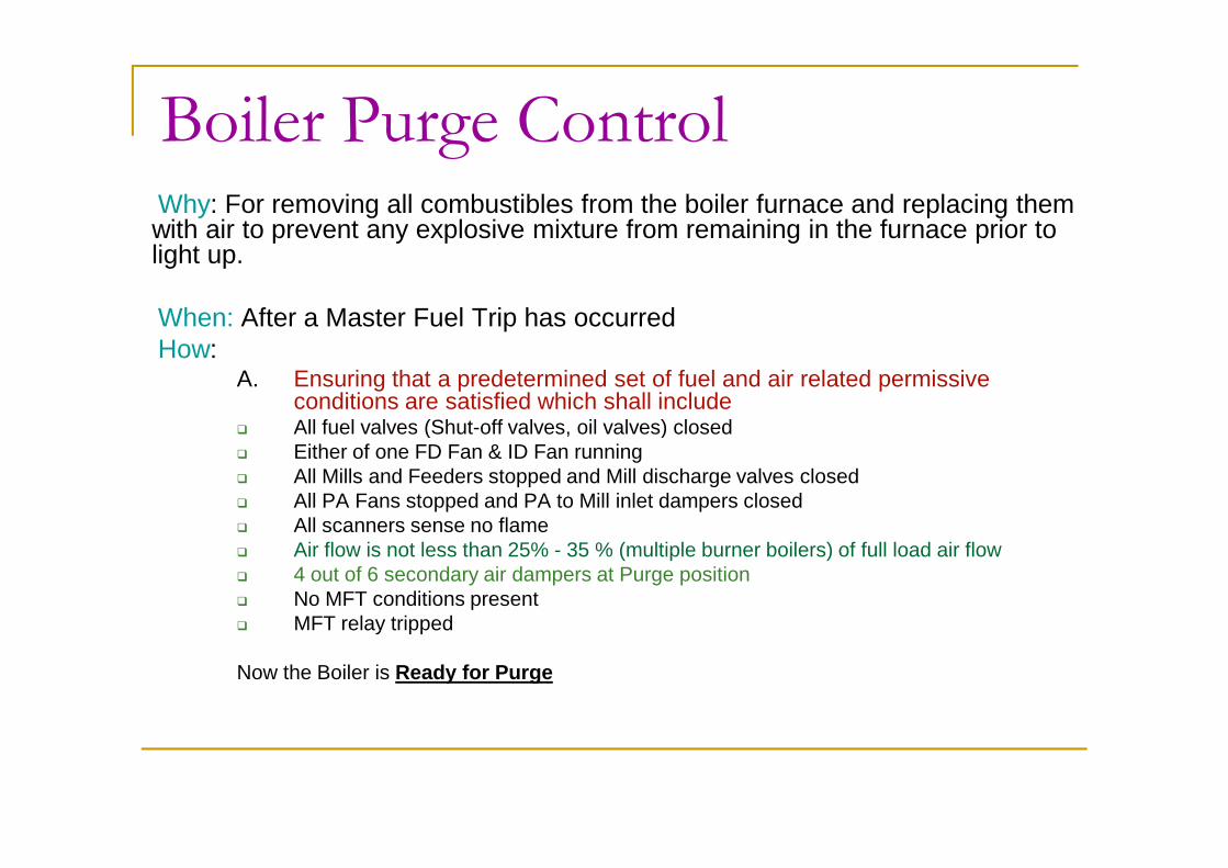
Boiler Purge ControlWhy: For removing all combustibles from the boiler furnace and replacing them with air to prevent any explosive mixture from remaining in the furnace prior to light up.
When: After a Master Fuel Trip has occurredHow:
A. Ensuring that a predetermined set of fuel and air related permissive conditions are satisfied which shall include
q All fuel valves (Shut-off valves, oil valves) closedq All fuel valves (Shut-off valves, oil valves) closedq Either of one FD Fan & ID Fan running q All Mills and Feeders stopped and Mill discharge valves closedq All PA Fans stopped and PA to Mill inlet dampers closedq All scanners sense no flameq Air flow is not less than 25% - 35 % (multiple burner boilers) of full load air flowq 4 out of 6 secondary air dampers at Purge positionq No MFT conditions presentq MFT relay tripped
Now the Boiler is Ready for Purge

Boiler Purge Control
B. Initiate Boiler Purgeq Dampers are initiated to move to Purge position (air flow 30 to 80 T/hr)q 5 minute purge timer triggersq Boiler purge in progress is indicated
After 5 minutes has elapsed the Purge process is complete and the boiler is ready for firingIf any of the condition mentioned in ‘A’ fails during purging process, purging is interrupted and the timer resets.
Fuel Safety Control
Why: To prevent any explosive condition in the furnace
What: Withdraws fuel feed to the Furnace
When: If any of the predetermined trip conditions has occurred.
ClassificationDepending on the fuels involved the fuel safety control can be made up of the following:q Master fuel tripq Oil fuel trip
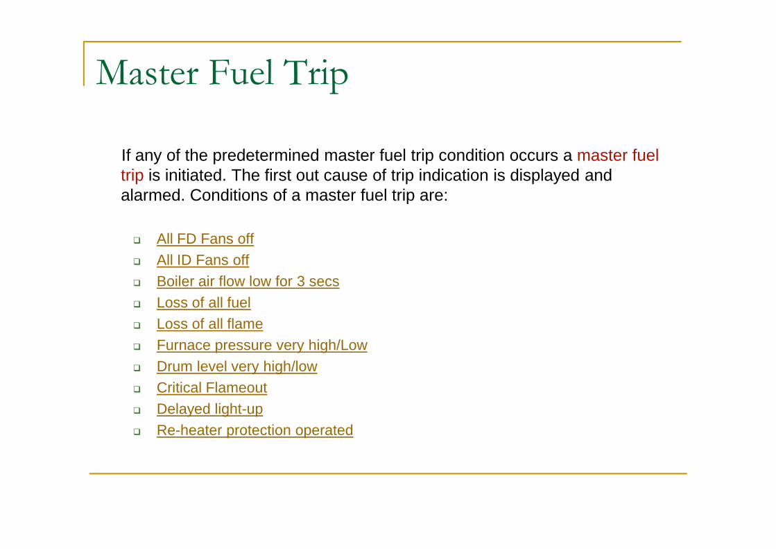
Master Fuel Trip
If any of the predetermined master fuel trip condition occurs a master fuel trip is initiated. The first out cause of trip indication is displayed and alarmed. Conditions of a master fuel trip are:
q All FD Fans off
q All ID Fans off
Boiler air flow low for 3 secsq Boiler air flow low for 3 secs
q Loss of all fuel
q Loss of all flame
q Furnace pressure very high/Low
q Drum level very high/low
q Critical Flameout
q Delayed light-up
q Re-heater protection operated

Master Fuel Trip
Some more Conditions of a master fuel trip (continued) :q Loss of HT powerq Loss of UPS powerq Loss of 220V DC powerq Condenser vacuum very lowq MFT hard relay trippedq 2 out of 3 main processors failedq 2 out of 3 main processors failedq Both emergency trip push buttons operatedAny of the above occasions will result in a MFT
MFT can be reset whenq None of the above trip conditions existq Boiler purge is completeq Reset MFT is initiated
NEXT
MFT – all FD fans off
n All FD fans Off
Source : Breaker off signal from both fans
Implication: Will result in in-sufficient air for the combustion process and the fuel cannot burn
Action: MFT
MFT conditions
MFT – all ID fans off
n All ID fans Off
Source : Breaker off signal from all 3 fans
Implication: Will result in an uncontrolled furnace Implication: Will result in an uncontrolled furnace pressurization.
Action: MFT
MFT conditions
MFT – Air flow less than 25%
n Boiler air flow less than < 25% for 3 secs
Source : Flow transmitters at FD suction
Implication: Will result in in-sufficient air for the Implication: Will result in in-sufficient air for the combustion process and the fuel cannot burn completely
Action: MFT
MFT conditions
MFT – Loss of all fuel
n Loss of all fuel
Source : Any oil burner in operation (MFT trip resets)and closure of all burner valves and all Mills ‘off’ and no mill in shutdown mode.
Implication: As no fuel is being fed into the furnace generation of heat for sustenance of combustion and subsequent production of steam cannot take place
Action: MFTMFT conditions

MFT – Loss of all flame
n Loss of all flame
Source : Any oil burner in operation and no scanners see flame.
Implication: Will proactively safeguard all adverse effect due to non burning of fuel (detected from the intensity of flame) being injected into the furnace
Action: MFTMFT conditions
MFT – Furnace pressure very high/low
n Furnace pressure very high /low
Source : Pressure switch and transmitter.
Implication: Will result in explosion or implosion of the furnace resulting in mechanical deformity
Action: MFT
MFT conditions
MFT – Drum level very high/low
n Drum level very high / low
Source : Hydrastep and drum level transmitter
Implication:High: Will result in Flooding of superheaters causing a. carryover of dissolved solids and hence deposition downstream effecting a. carryover of dissolved solids and hence deposition downstream effecting heat transfer b. fall of steam temperature and quenching of Turbine
Low: Will result in starvation of water in the furnace tubes which will lead to tube metal overheating as no cooling medium is present
Action: MFTMFT conditions
MFT – Critical flameout
n Critical Flameout
Source : Furnace flame scanners detect 2 out of 3 zones no flame
Implication: Is a consequence of improper combustion in Implication: Is a consequence of improper combustion in pre-identified zones within the furnace resulting in flame instability which may give rise to improper heat distribution
Action: MFTMFT conditions
MFT – Delayed light-up
n Delayed light up
Source : MFT reset , LDO shut off valves open and no oil gun in operation (or in other words put into service) within 10 mins of opening of LDO shut-off valves.
Implication: Repeated unsuccessful attempts to light up the boiler with oil gun has resulted in accumulation of un-burnt fuel (oil) in the furnace and hence the furnace requires purging.
Action: MFTMFT conditions
MFT – Re-heater protection
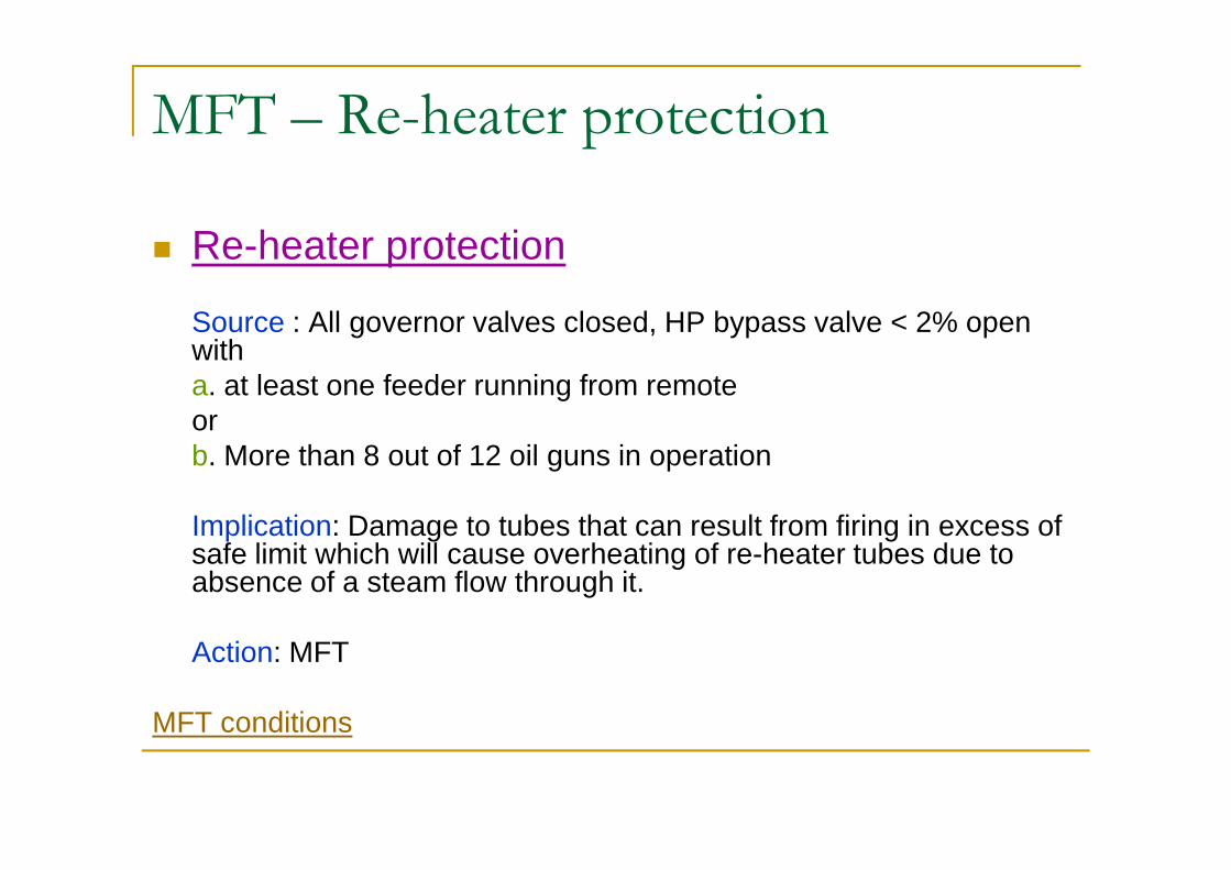
n Re-heater protection
Source : All governor valves closed, HP bypass valve < 2% open witha. at least one feeder running from remote or or b. More than 8 out of 12 oil guns in operation
Implication: Damage to tubes that can result from firing in excess of safe limit which will cause overheating of re-heater tubes due to absence of a steam flow through it.
Action: MFT
MFT conditions
MFT – Condenser Vacuum Low
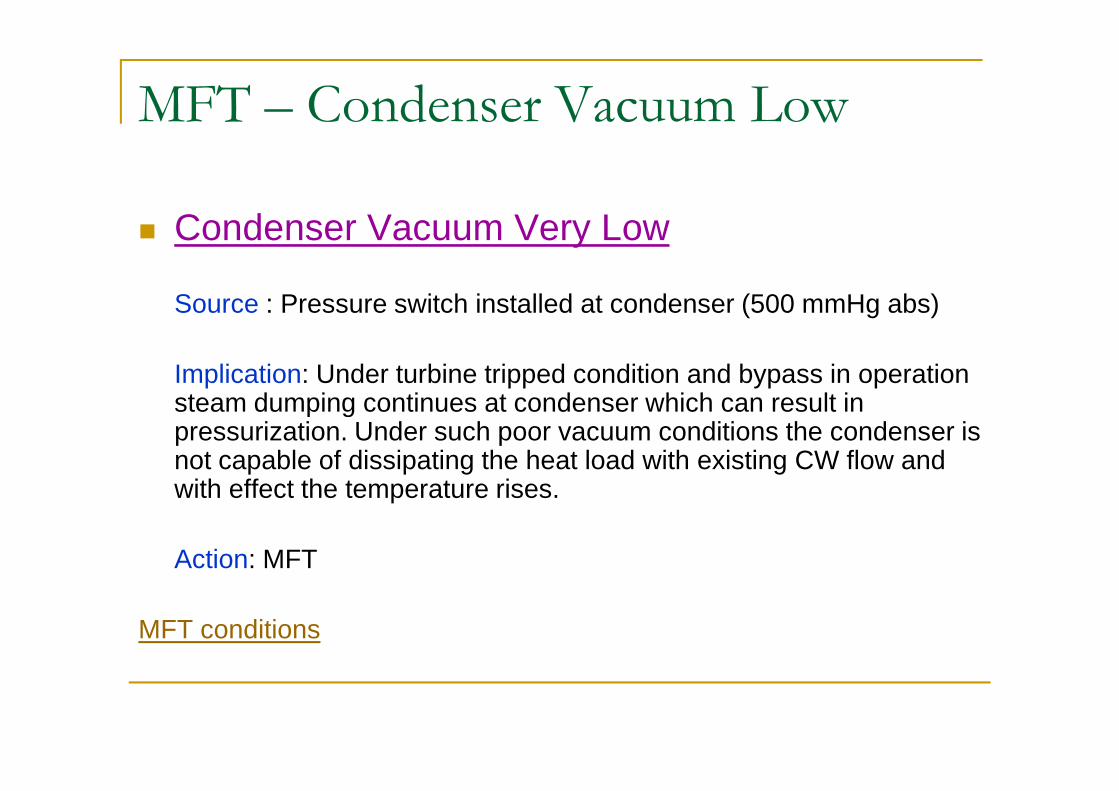
n Condenser Vacuum Very Low
Source : Pressure switch installed at condenser (500 mmHg abs)
Implication: Under turbine tripped condition and bypass in operation steam dumping continues at condenser which can result in steam dumping continues at condenser which can result in pressurization. Under such poor vacuum conditions the condenser is not capable of dissipating the heat load with existing CW flow and with effect the temperature rises.
Action: MFT
MFT conditions

Oil Fuel TripIf any of the predetermined oil fuel trip conditions is exceeded the oil fuel trip is initiated. The first out cause of trip indication is displayed and alarmed. All oil fuel is removed from the boiler and all oil burners are shutdown. Depending on other conditions a master fuel trip may be generated. Conditions of an oil fuel trip are:
q LDO trip valves close commandq LDO trip valves not closed and LDOT condition is presentq LDOT relay fail to trip and LDOT condition is presentq LDO pressure very low for 3 secs and any LDO burner valves not closedq Atomising air pressure very low for 3 secs and any LDO burner valves not closed q LDO trip valve not open within 10 secs of LDOT resetq Any burner valve fail to close despite boiler load being > 50%q Any burner valve fail to close despite boiler load being > 50%q LDOT hard relay tripped
LDOT can be reset whenq None of the above trip conditions existq MFT relay is resetq Trip valve open is initiatedq All LDO burner valves are closed

Mill Trip Conditions
The following conditions shall cause a Mill to tripq LOS or emergency stop pressed
q Mill and feeder running from remote, oil flame not detected with either feeder speed <30 % or coal flame not detected signifying low coal and no ignition source
q Feeder running from remote and coal and oil flame neither detected assuming flame monitoring system is healthy signifying loss of coal flame without ignition flame monitoring system is healthy signifying loss of coal flame without ignition source
q Loading gas pressure very low
q Lub oil pressure very low signifying no lubrication to Mill gear box and bearings
q Both PA fans stopped
q Mill running from remote for >30 secs and PA flow below minimum
q Mill running from remote for >30 secs and Secondary air flow < 45%
q Seal air pressure very low
q MFT or Mill hard relay
Preferential Mill Tripping
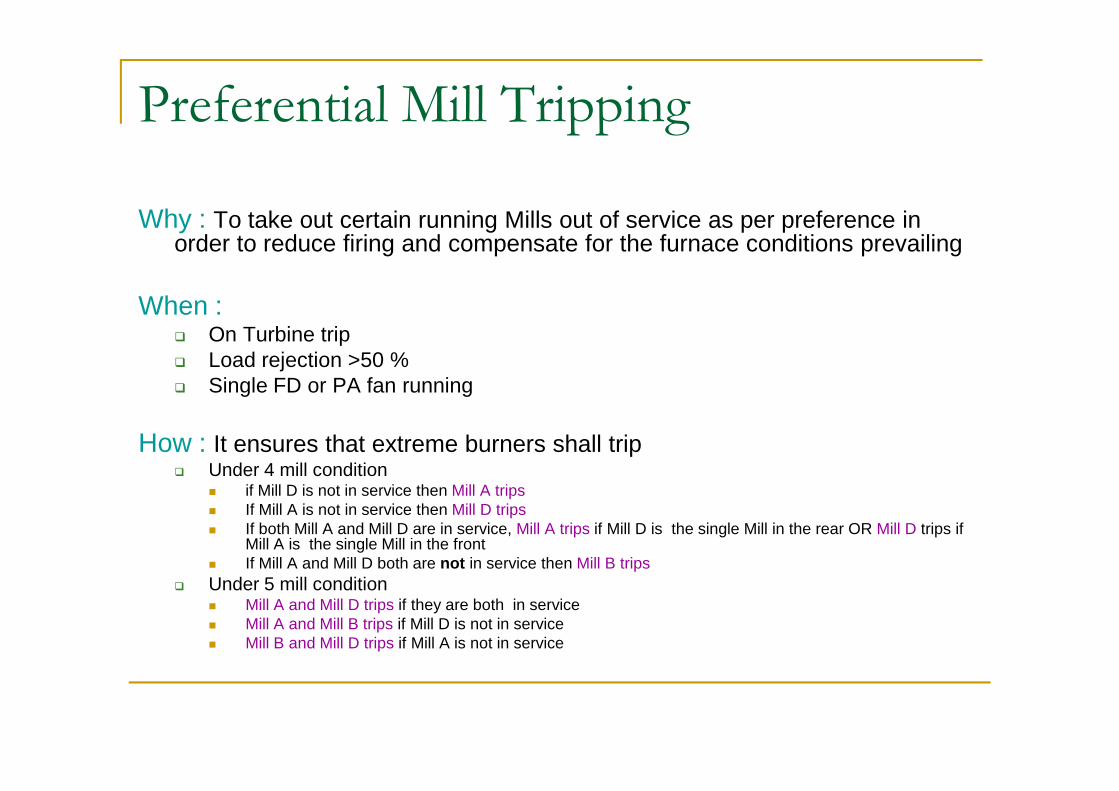
Why : To take out certain running Mills out of service as per preference in order to reduce firing and compensate for the furnace conditions prevailing
When :q On Turbine tripq Load rejection >50 %q Single FD or PA fan runningq Single FD or PA fan running
How : It ensures that extreme burners shall tripq Under 4 mill condition
n if Mill D is not in service then Mill A tripsn If Mill A is not in service then Mill D tripsn If both Mill A and Mill D are in service, Mill A trips if Mill D is the single Mill in the rear OR Mill D trips if
Mill A is the single Mill in the frontn If Mill A and Mill D both are not in service then Mill B trips
q Under 5 mill conditionn Mill A and Mill D trips if they are both in service n Mill A and Mill B trips if Mill D is not in servicen Mill B and Mill D trips if Mill A is not in service
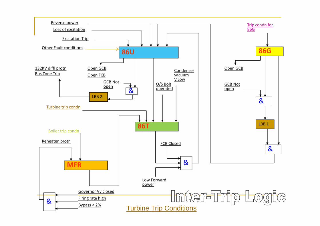
86G86U
Open GCB
GCB Not open
&
O/S Bolt operated
Condenser vacuum V.Low
Turbine trip condn
Open GCBOpen FCB
GCB Not open
&LBB 2
132KV diffl protnBus Zone Trip
Reverse powerLoss of excitation
Excitation Trip
Trip condn for 86G
Other Fault conditions
86T
MFR
Boiler trip condn
Reheater protn
&
Low Forward power
FCB Closed
LBB 1
&
Governor Vv closedFiring rate highBypass < 2%
&Turbine Trip Conditions

Control & Instrumentation in Thermal Power Plant

PRIMARYCRUSHER
COAL & PRIMARY
AIR
WAGON
RAILWAYTRACK
COAL
BUNKER
S U P E R
H E A T E R
DRUM
TURBINE GENERATOR
ID FAN
ESP
CHIMNEY
GOVERNER VALVE
TRANSFORMER
TO DISTRIBUTION
SYSTEM
COAL STOCK
ELECTRICITY
STEAMAPH
DRY ASH SILO
TO AMBUJA FOR PPC
CEMENT
HCSS
EXPORT OF ASH TO
BANGLADESH
GENERATOR
FEEDER
SECONDARYCRUSHER
ISH
COAL MILL
PA FAN
FD FAN
TURBINE GENERATOR
CONDENSER
CONDENSER COOLING WATER SYSTEM
FORE BAY
COOLING TOWER
CW PUMP
DM PLANT
RAW WATER TREATMENT
INTAKE PUMPS
RIVER GANGES
COAL ELECTRICITY
BOILER
FEED WATER
APH
AIR PRE HEATER
MAKE UP WATER SYSTEM
ZERO DISCHARGE
SYSTEM
BOTTOM ASH
BOTTOM ASH
HOPPER
BFP
SECON-DARY AIR
GENERATOR
CEPLPHD/A
HPHAIR INTAKE
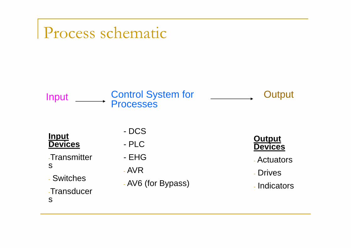
Process schematic
Control System for Processes
OutputInput
- DCS
- PLC
- EHG
- AVR
- AV6 (for Bypass)
Input Devices
-Transmitters
- Switches
-Transducers
Output Devices
- Actuators
- Drives
- Indicators

Controlled Parameters
Most commonly controlled parameters in Industry are:
1. Flow
2. Level2. Level
3. Temperature
4. Pressure
5. Speed (RPM)
6. Position

FLOWn Measured with
q Orifice, Nozzle
n Pressure drop measured with
q DP Transmitter
n Flow ∞ K √DPInput
DCS
DP
FLOW
Input
Processor
Output
4 to 20 mA signal
Valve
Actuator
4 to 20 mA signal
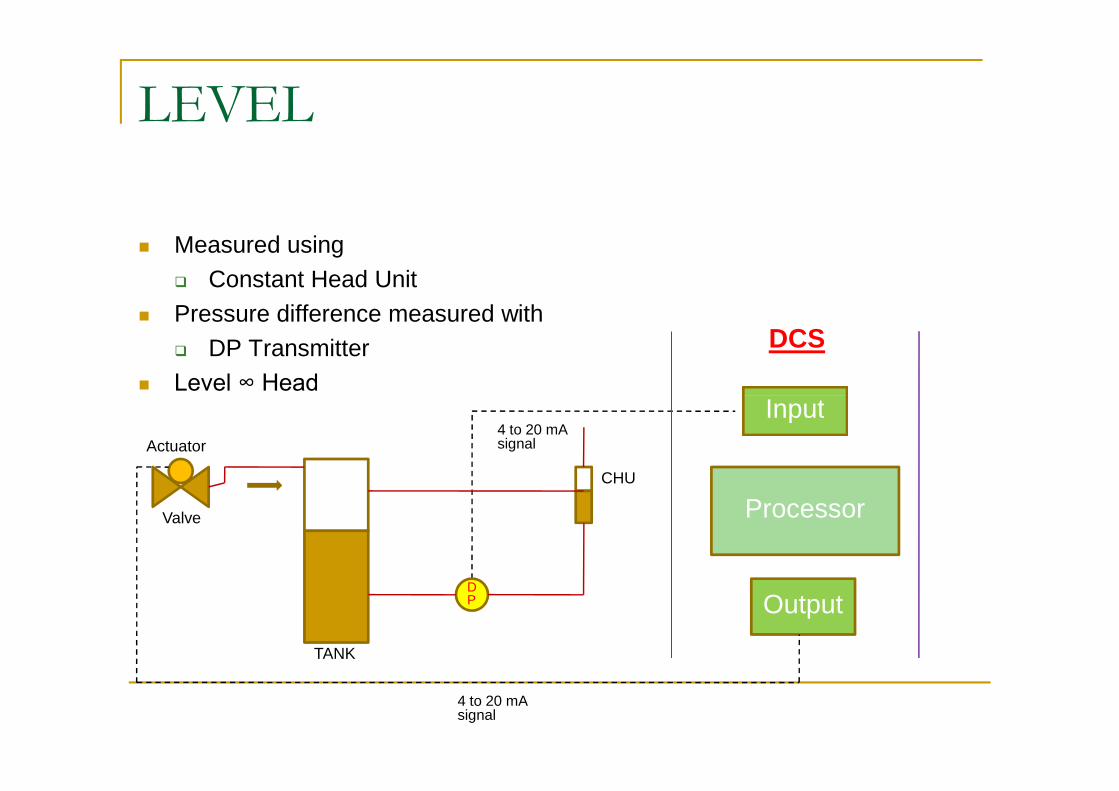
LEVEL
n Measured using
q Constant Head Unit
n Pressure difference measured with
q DP Transmitter
n Level ∞ HeadInput
DCS
Level ∞ HeadInput
Processor
Output
4 to 20 mA signal
Valve
Actuator
4 to 20 mA signal
DP
TANK
CHU
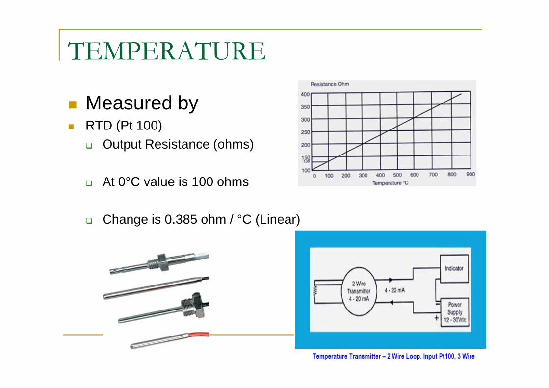
TEMPERATURE
n Measured byn RTD (Pt 100)
q Output Resistance (ohms)
q At 0°C value is 100 ohms
q Change is 0.385 ohm / °C (Linear)

TEMPERATURE
n Measured byn Thermocouple
q Output mVq Types: J,K,T,S….
• Temperature TransmitterOutput 4 to 20 mAn Output 4 to 20 mA
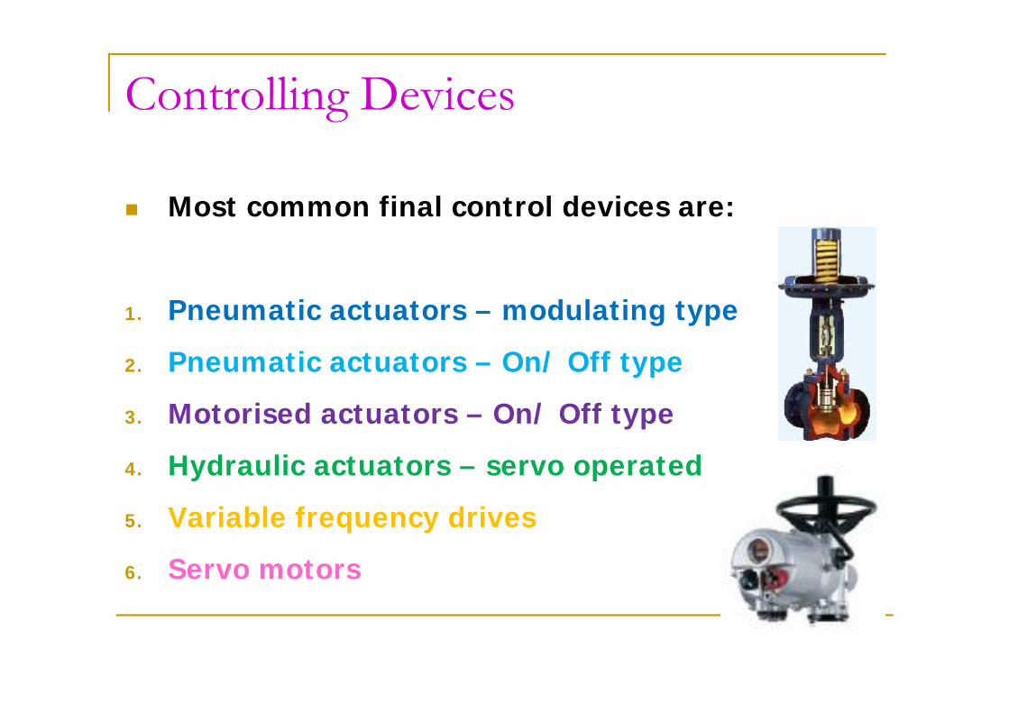
Controlling Devices
n Most common final control devices are:
1. Pneumatic actuators – modulating type
2. Pneumatic actuators – On/ Off type2. Pneumatic actuators – On/ Off type
3. Motorised actuators – On/ Off type
4. Hydraulic actuators – servo operated
5. Variable frequency drives
6. Servo motors

WHAT IS AUTOMATION?
What is in a Automation System?
Control Processor
Input to the System
Field Inputs (Transmitters/ Switches / Sensor)
Field Outputs (Valves / Pumps / others)
Input to the system
Systemoutput
INPUT MODULES OUTPUT MODULES

Examples of Boiler Controls
n Boiler Control System comprises the following functions
q Boiler Master Pressure Control
q Fuel Flow Control
q Feeder Speed Control
q Mill Air Flow Control and Temperature Control
q Excess Air Control
q Drum Level control
q Furnace Draft Control
q Super-heater Steam temperature Control
q Various other Pressure, Temperature, Level, Flow , Position Controls
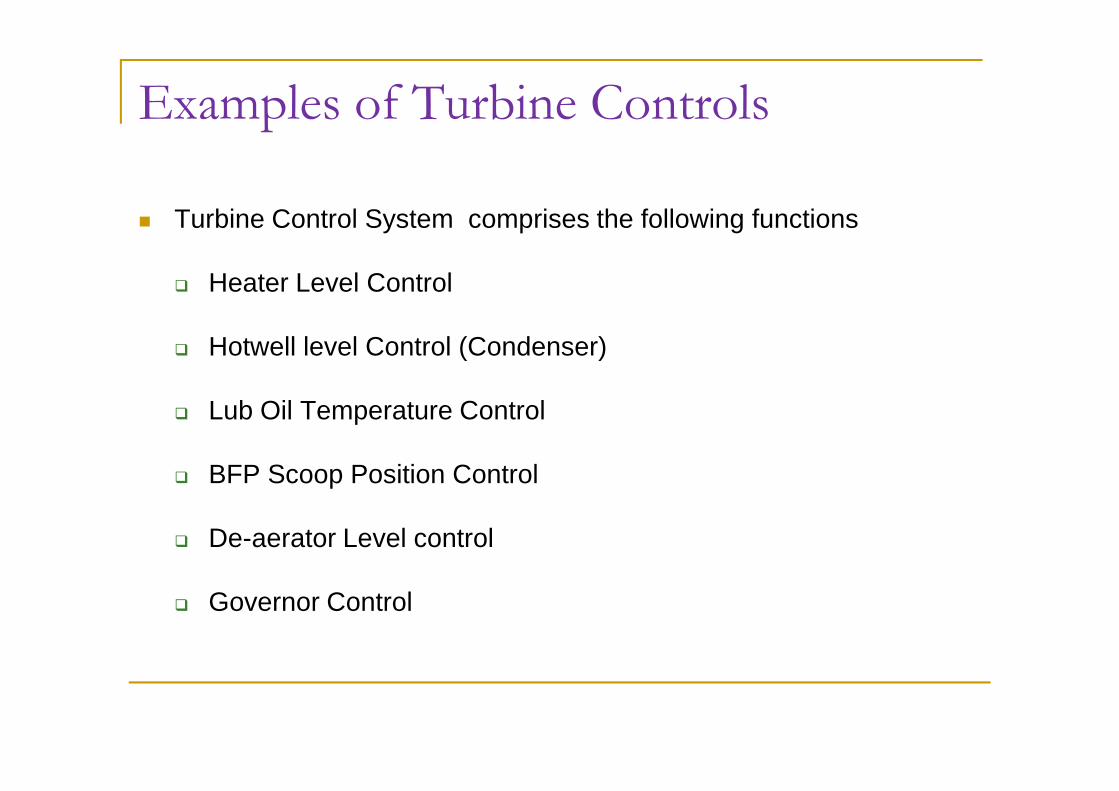
Examples of Turbine Controls
n Turbine Control System comprises the following functions
q Heater Level Control
q Hotwell level Control (Condenser)
q Lub Oil Temperature Control
q BFP Scoop Position Control
q De-aerator Level control
q Governor Control
Control System Hardware
PLC
DCS
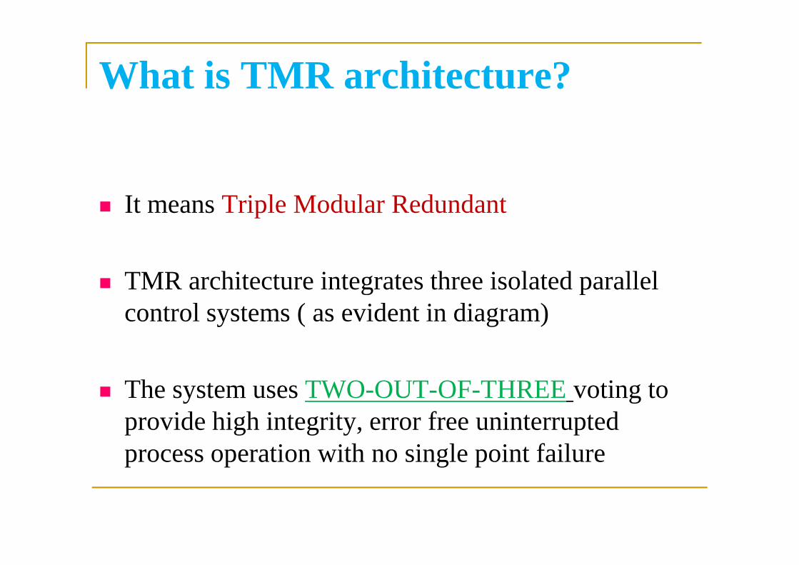
What is TMR architecture?
n It means Triple Modular Redundant
n TMR architecture integrates three isolated parallel n TMR architecture integrates three isolated parallel control systems ( as evident in diagram)
n The system uses TWO-OUT-OF-THREE voting to provide high integrity, error free uninterrupted process operation with no single point failure

Hardware - PLC
n EFFECTIVE AND RELIABLE SYSTEM FOR OVERALL SUPERVISION OF BOILER SAFETY IN A POWER PLANT.
n CONTAINS SAFETY GUIDELINES
Transferring control to Fault Tolerant pair and running
self diagnostics
PROGRAMMED INSIDE FOR
– TAKING PREVENTIVE MEASURES
– IN EXTREME CASES TO TAKE THE WHOLE SYSTEM TO STEP-BY-STEP SHUTDOWN.
n IT FORESEES FUTURE ERROR AND GENERATE ALARMS. Running self
diagnostics and monitoring
Chassis with
Processor and I/O
cards

Hardware - PLC
n THE BMS IS A PLC, PROGRAMMED ACCORDING TO USER NEED.n LIKE CONVENTIONAL PLC SYSTEMS THE BMS ALSO CONSISTS
OF THE FOLLOWING PARTS:-1. MOUNTING RACK FOR HOUSING THE WHOLE PLC
SYSTEM.2. POWER SUPPLY FOR SUPPLYING POWER TO THE
PLC SYSTEM.PLC SYSTEM.3. MAIN PROCESSOR THE BRAIN OF THE SYSTEM4. I/O CARDS INTERFACING UNITS BETWEEN
SYSTEM & FIELD5. SPECIAL MODULES COMMUNICATION WITH OTHER
SYSTEMS, ETC.6. SPECIAL FUNCTIONS HIGH SPEED COUNTER,
THERMOCOUPLE SENSORS (NOT IN BBGS)
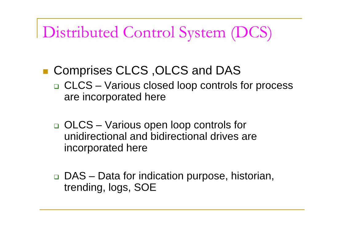
Distributed Control System (DCS)
n Comprises CLCS ,OLCS and DASq CLCS – Various closed loop controls for process
are incorporated here
OLCS – Various open loop controls for q OLCS – Various open loop controls for unidirectional and bidirectional drives are incorporated here
q DAS – Data for indication purpose, historian, trending, logs, SOE
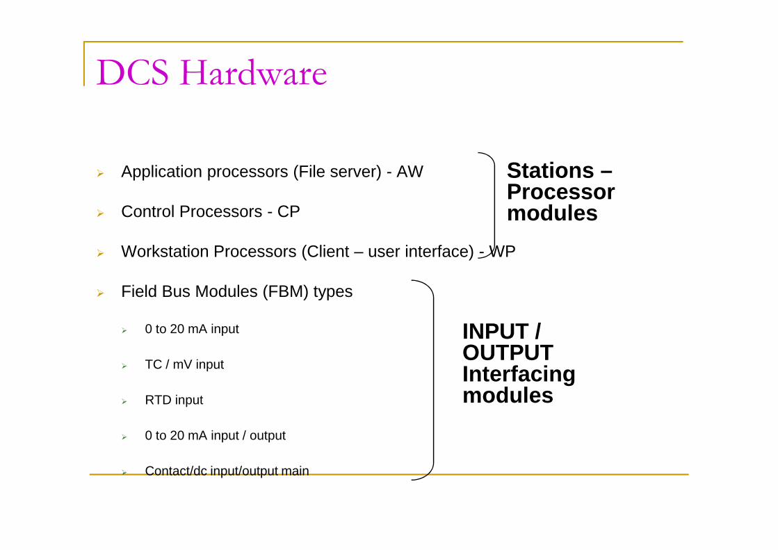
DCS Hardware
Ø Application processors (File server) - AW
Ø Control Processors - CP
Ø Workstation Processors (Client – user interface) - WP
Stations –Processor modules
Ø Field Bus Modules (FBM) types
Ø 0 to 20 mA input
Ø TC / mV input
Ø RTD input
Ø 0 to 20 mA input / output
Ø Contact/dc input/output main
INPUT / OUTPUT Interfacing modules

DCS Architecture – Bus Topology
Application Processor Workstation Processor
Ethernet IEEE 802.3
Control ProcessorFT
FBMS FOR CLCS/OLCS & DAS
NODE BUS
FIELD BUS
Input & Output
Redundant Switches
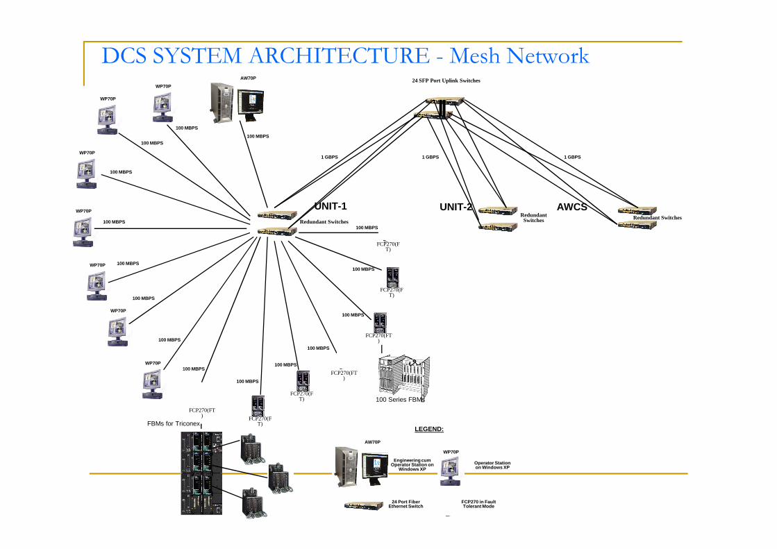
DCS SYSTEM ARCHITECTURE - Mesh Network
UNIT-2 AWCSUNIT-1
WP70P
Redundant SwitchesRedundant Switches
24 SFP Port Uplink Switches
1 GBPS 1 GBPS 1 GBPS
AW70P
WP70P
WP70P
WP70P
WP70P
FCP270(FT)
100 MBPS
100 MBPS
100 MBPS
100 MBPS
100 MBPS
100 MBPS100 MBPS
100 MBPS
FCP270(FT)
WP70P
LEGEND:
Engineering cum Operator Station on
Windows XPOperator Station on Windows XP
24 Port Fiber Ethernet Switch
FCP270 in Fault Tolerant Mode
AW70P
WP70P
WP70P
FCP270(FT)
FCP270(FT)
FCP270(FT)
FCP270(FT)
FCP270(FT)
FBMs for Triconex
100 Series FBMs
100 MBPS
100 MBPS
100 MBPS
100 MBPS
100 MBPS
100 MBPS
100 MBPS

DCS Hardware (OLCS)
n Field Inputn DCS Marshalling Rackn IA Enclosure – DCS (Logic)n DCS Relay Rack
INPUT
DCS Relay Rackn DCS Marshalling Rackn MCC Modulen Drive (Motor)
OUTPUT
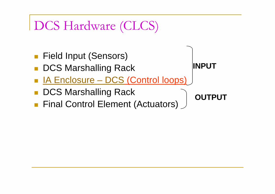
DCS Hardware (CLCS)
n Field Input (Sensors)n DCS Marshalling Rackn IA Enclosure – DCS (Control loops)n DCS Marshalling Rack
INPUT
OUTPUTDCS Marshalling Rack
n Final Control Element (Actuators)OUTPUT
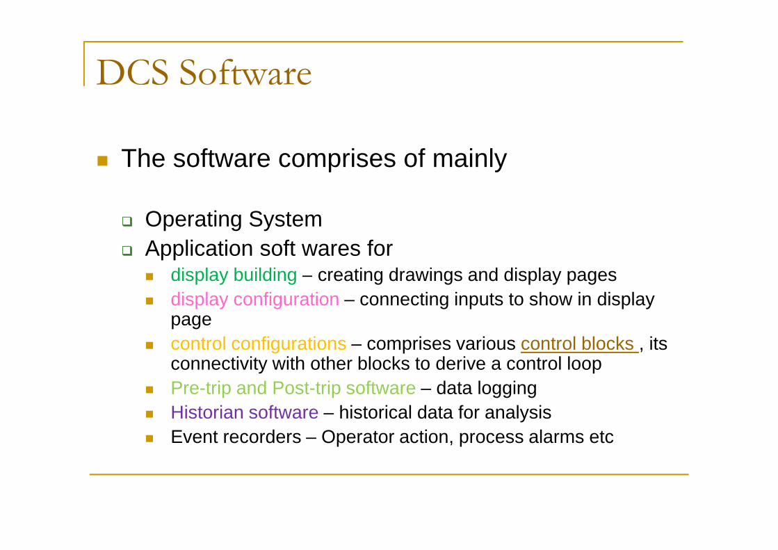
DCS Software
n The software comprises of mainly
q Operating Systemq Application soft wares for
n display building – creating drawings and display pages n display building – creating drawings and display pages n display configuration – connecting inputs to show in display
page n control configurations – comprises various control blocks , its
connectivity with other blocks to derive a control loopn Pre-trip and Post-trip software – data loggingn Historian software – historical data for analysisn Event recorders – Operator action, process alarms etc
IFL-1 CIN-2 OFL-10 CIN-20 TC02-S CIN-6 INT-04 CO-1
CRT STARTREMOTE
SS IN PUMP INMANUAL
JOP SUCPR LO ELEC TR8
NO MOD INSERV
STOP
CIN-7
MOD INTEST
CIN-17 CIN-1
INT-02
CO-1
ACJOP
STARTSS INLOCAL
LOCAL
AUT STR
STR / STPACJOP
IFL-2
STR / STPACJOP
CIN-2
SS INREMOTE
CRT STOP
CIN-18
AUTO
STOPLOCAL
CIN-19 OFL-11 CIN-2
SS INREMOTE
TRB SPDLT 1000
PUMP IN
TC01-S
JOP SUCPR LO
INT-04
STOP
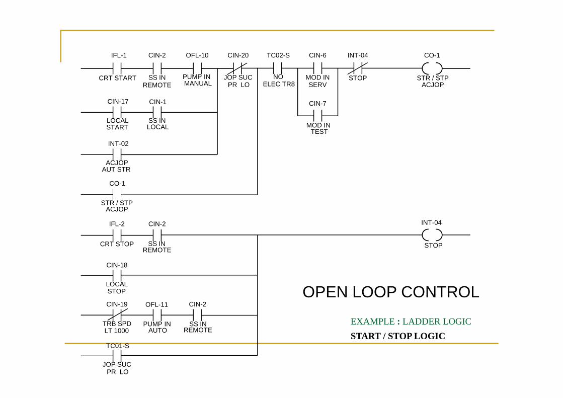
EXAMPLE : LADDER LOGIC
START / STOP LOGIC
OPEN LOOP CONTROL
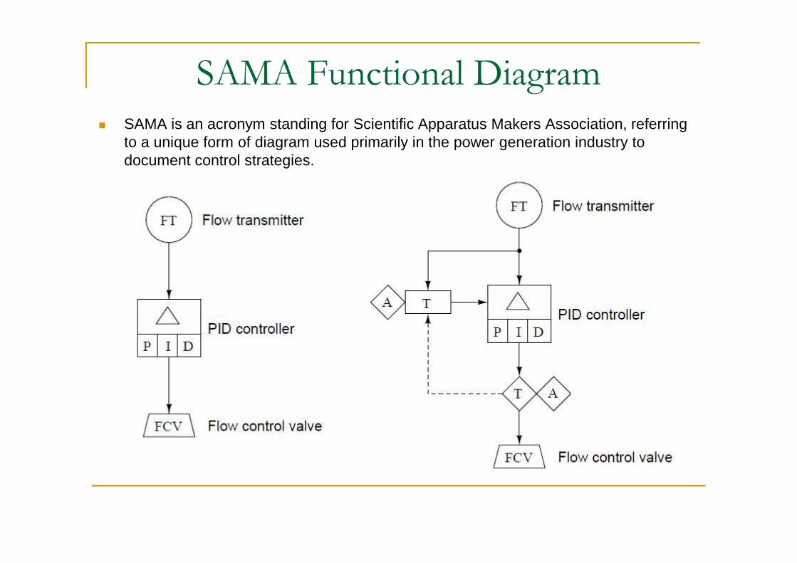
SAMA Functional Diagramn SAMA is an acronym standing for Scientific Apparatus Makers Association, referring
to a unique form of diagram used primarily in the power generation industry to document control strategies.

Standard SAMA Symbols

PID Controller

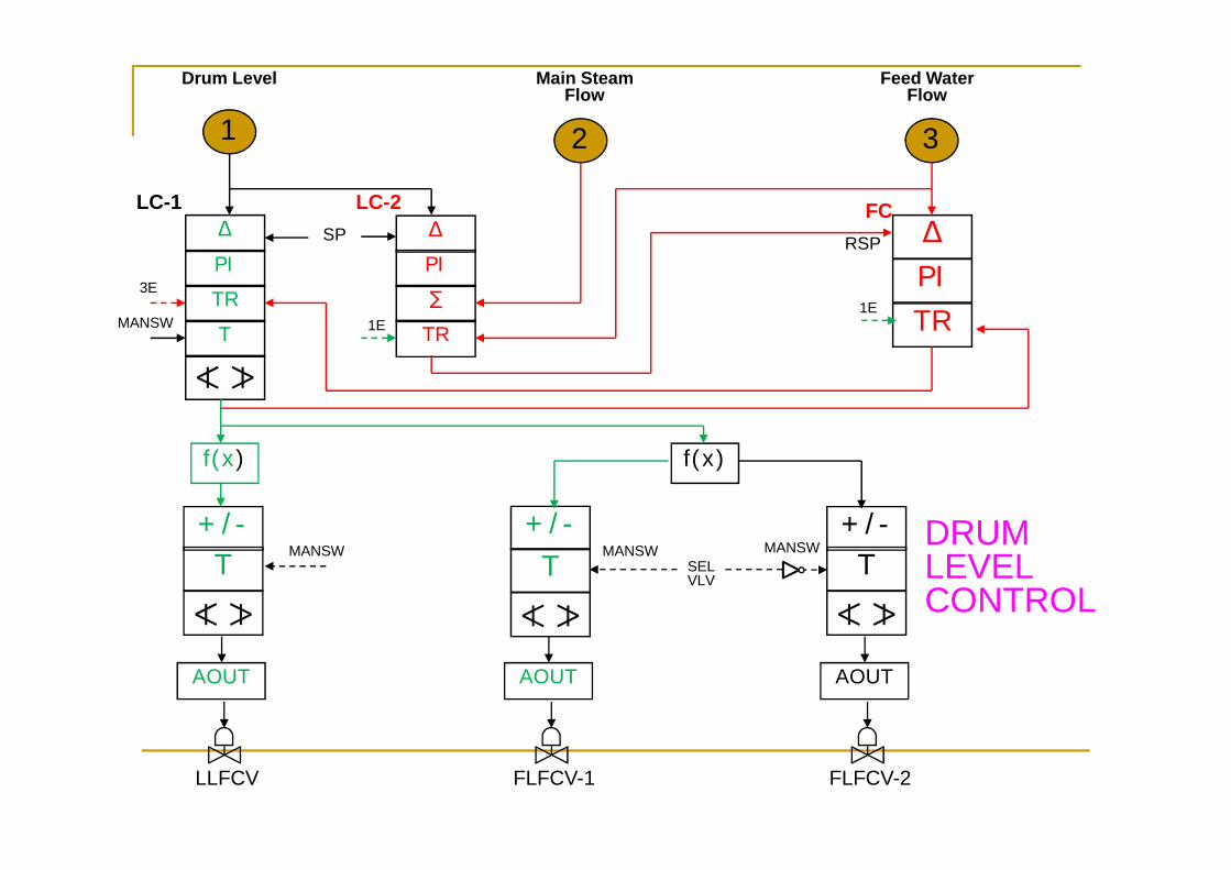
DRUM LEVEL CONTROL
AIN AIN AIN
LT LTLT
DRUM LEVEL LHS
AIN AIN AIN
PT PTPT
AIN AIN AIN
LT LTLT
DRUM PRESSURE DRUM LEVEL RHS
1
∑/2
CALC CALCf(x)
DENSITY COMPENSATED
DRUM LEVEL

DRUM LEVEL CONTROL
AIN AIN AIN
FT FTFT
MAIN STEAM FLOW
AIN AIN
PT PT
AIN AIN AIN
TT TTTT
MAIN STEAM PRESSURE MAIN STEAM TEMP
T
BAD
2
CALC CALC
PRESSURE,TEMP COMPENSATED TOTAL STEAM FLOW
AUXILIARY STEAM FLOW
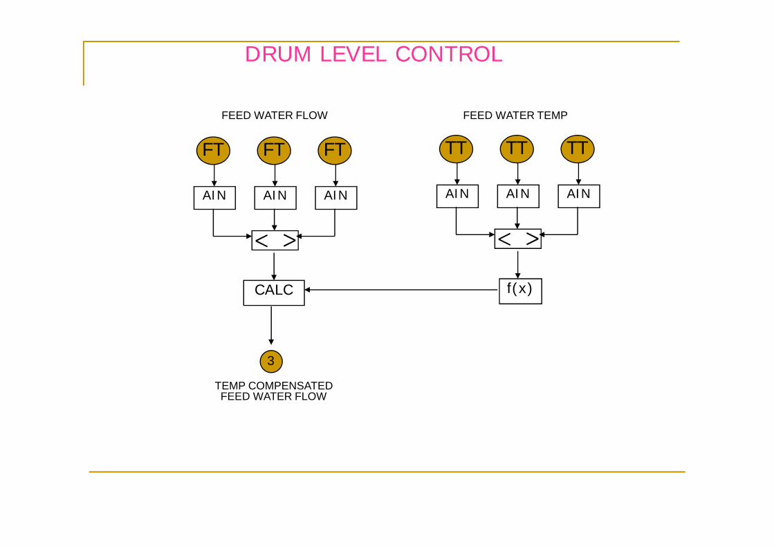
DRUM LEVEL CONTROL
AIN AIN AIN
FT FTFT
FEED WATER FLOW
AIN AIN AIN
TT TTTT
FEED WATER TEMP
3
CALC
TEMP COMPENSATED FEED WATER FLOW
f(x)
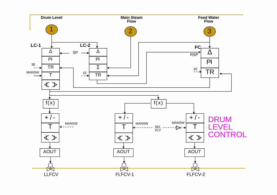
21
Δ
PI
∑
TR
Δ
PI
TR
T
SP
3
ΔPITR
RSP
LC-2 FC
MANSW
Drum Level Main Steam Flow
Feed Water Flow
LC-1
3E
1E1E
+/-T
f(x)
MANSW
AOUT
LLFCV
+/-T
AOUT
FLFCV-1
+/-T
f(x)
AOUT
FLFCV-2
MANSWSEL VLV
MANSW DRUM LEVEL CONTROL
21
Δ
PI
∑
TR
Δ
PI
TR
T
SP
3
ΔPITR
RSP
LC-2 FC
MANSW
Drum Level Main Steam Flow
Feed Water Flow
LC-1
3E
1E1E
+/-T
f(x)
MANSW
AOUT
LLFCV
+/-T
AOUT
FLFCV-1
+/-T
f(x)
AOUT
FLFCV-2
MANSWSEL VLV
MANSW DRUM LEVEL CONTROL

21
Δ
PI
∑
TR
Δ
PI
TR
T
SP
3
ΔPITR
RSP
LC-2 FC
MANSW
Drum Level Main Steam Flow
Feed Water Flow
LC-1
3E
1E1E
+/-T
f(x)
MANSW
AOUT
LLFCV
+/-T
AOUT
FLFCV-1
+/-T
f(x)
AOUT
FLFCV-2
MANSWSEL VLV
MANSW DRUM LEVEL CONTROL