Page 1
CONTROL OF AN INVERTED PENDULUM USING FUZZY LOGIC
MOHD HAFIZAN BIN ANUAR
This report is submitted in partial fulfillment of the requirement for the award of
Bachelor of Electronic Engineering (Industrial Electronic) With Honours
Faculty of Electronic and Computer Engineering
University Teknikal Malaysia Melaka
April 2009
Page 2
UNIVERSTI TEKNIKAL MALAYSIA MELAKA FAKULTI KEJURUTERAAN ELEKTRONIK DAN KEJURUTERAAN KOMPUTER
BORANG PENGESAHAN STATUS LAPORAN
PROJEK SARJANA MUDA II
Tajuk Projek : CONTROL OF AN INVERTED PENDULUM USING FUZZY LOGIC
Sesi Pengajian : 2008/2009
Saya …………………..………MOHD HAFIZAN BIN ANUAR………………………………….
(HURUF BESAR)
mengaku membenarkan Laporan Projek Sarjana Muda ini disimpan di Perpustakaan dengan syarat-
syarat kegunaan seperti berikut:
1. Laporan adalah hakmilik Universiti Teknikal Malaysia Melaka.
2. Perpustakaan dibenarkan membuat salinan untuk tujuan pengajian sahaja.
3. Perpustakaan dibenarkan membuat salinan laporan ini sebagai bahan pertukaran antara institusi
pengajian tinggi.
4. Sila tandakan ( √ ) :
SULIT*
(Mengandungi maklumat yang berdarjah keselamatan atau
kepentingan Malaysia seperti yang termaktub di dalam AKTA
RAHSIA RASMI 1972)
TERHAD*
(Mengandungi maklumat terhad yang telah ditentukan oleh
organisasi/badan di mana penyelidikan dijalankan)
TIDAK TERHAD
Disahkan oleh:
__________________________ ___________________________________
(TANDATANGAN PENULIS) (COP DAN TANDATANGAN PENYELIA)
Alamat Tetap: No. 10, Lorong Lengkongan,
Kg. Raja Uda, 42000 Pelabuhan Klang,
Selangor
Tarikh : 27 April 2009 Tarikh: ………………………..
Page 3
iii
“I hereby declare that this report is the result of my own except for quotes as cited in
the references”.
Signature :……………………………..
Author :…………………………….
Date :……………………………..
Page 4
iv
“I hereby declare that I have read this report and in my opinion this report is
sufficient in terms of the scope and quality for the award of Bachelor of Electronic
Engineering (industrial Electronic) With Honours.”
Signature :…………………………………
Supervisor’s Name :…………………………………
Date :…………………………………
Page 5
v
I dedicated this to my lovely family, lecturers and friends.
Page 6
vi
ACKNOWLEDGEMENT
Firstly, I would like to thank to the Almighty God, Allah SWT that had gave
me an opportunity to finish this final year project successfully. Without His bless
there are nothing could be done in such a way.
My appreciation also goes to my family who has been so tolerant and
supporting me all these years. Their love, emotional and spiritual support that they
gave to me had encouraged me to do the best to achieve success in the future.
Besides that, I would like to express my heartily gratitude to my supervisor.
Mr. Mohd Shakir bin Md Saat for the guidance, enthusiasm and support given
throughout the progress of this project.
Nevertheless, thanks al lot to all Inverted Pendulum group members that had
been helping me from the beginning till the end of this project. Their support had
encouraged me to give the best in this project.
Lastly, not to forget to all my housemates and BENE classmates and those
whom contribute in directly or indirectly to complete this report, thanks a lot, may
Allah bless you all.
.
Page 7
vii
ABSTRACT
Inverted Pendulum System is a physical device consisting in a cylindrical bar
which is usually made of aluminium, free to oscillate around a fixed pivot. The pivot
is mounted on a cart, which can only moves in a horizontal direction. The cart can be
exerted by a variable force. The bar would naturally tend to fall down from the top
vertical position, which is a position of unsteady equilibrium. The goal of this project
is to stabilize the inverted pendulum in upright position at all times while the cart
stops at desired position. This is possible by exerting on the cart through the motor a
force which tends to contrast the ‘free’ pendulum dynamics. The correct force has to
be calculated measuring the instant values of the horizontal position and the
pendulum’s angle. The controller used in this project is the Fuzzy Logic Controller.
The modeling and analysis for this controller is done in MATLAB and Simulink.
Therefore, the best control approach needs to be discovered in order to give the best
performance for the inverted pendulum system. For this purpose the fuzzy logic
controller is used with two sets of rules: first for swinging up the pendulum, and
second for balancing the pendulum in upper position. Besides that, the inverted
pendulum is also need to be placed at a desired location at the rail. Therefore, the
best results we achieved with a combination of fuzzy and state controller which is
PID.
Page 8
viii
ABSTRAK
‘Inverted Pendulum System’ adalah suatu alat yang terdiri daripada rod
silinder yang selalunya diperbuat daripada aluminium, bebas untuk berpusing di atas
suatu paksi yang tetap. Paksi tersebut terletak di atas kereta (cart) yang mana hanya
boleh bergerak dalam arah melintang. Kereta ini mempunyai motor yang boleh
dikenakan daya yang berubah-ubah ke atasnya. Rod tersebut akan cenderung untuk
jatuh ke bawah daripada kedudukan menegak di mana ia adalah kedudukan yang
tidak mencapai keseimbangan. Tujuan utama projek ini adalah untuk mengayunkan
bendul ke atas dan pada masa yang sama ia seimbang pada posisi ini dengan keadaan
posisi kereta yang dikehendaki. Ini boleh terjadi dengan mengenakan daya pada
kereta tersebut melalui motor di mana daya ini berlawanan dengan dinamik bandul
(pendulum). Daya yang betul dan sesuai hendaklah dikira dengan mengambil kira
tentang nilai kedudukan melintang kereta tersebut serta sudut bandul (pendulum)
dari paksi menegak. Pengawal (controller) yang digunakan dalam projek ini ialah
Pengawal Logik Fuzy (Fuzzy Logic Controller). Pemodelan dan analisis ke atas
pengawal (controller) ini dilakukan dalam MATLAB dan Simulink. Kemudian,
pengawal (controller) ini dianalisis terutama sekali terhadap masa yang diambil
untuk menstabilkan bandul dan juga kedudukan kereta. Oleh itu, pengawal
(controller) yang paling baik dan sesuai perlu dicari untuk menghasilkan
persembahan yang terbaik untuk ‘Inverted Pendulum System’. Untuk tujuan tersebut,
Pengawal Logic Fuzzy (Fuzzy Logic Controller) digunakan dengan 2 set peraturan:
pertama untuk mengayunkan bendul ke atas dan kedua menyeimbangkan bendul
tersebut pada posisi yang paling atas. Keputusan terbaik yang dicapai adalah dengan
menggunakan kombinasi pengawal jenis ‘fuzzy’ dan pengawal jenis ‘state’ iaitu PID.
Page 9
ix
TABLE OF CONTENTS
CHAPTER TITLE PAGE
PROJECT TITLE i
STATUS REPORT APPROVEMENT FORM ii
DECLARATION FORM iii
SUPERVISOR’S APPROVEMENT iv
DEDICATION v
ACKNOWLEGDEMENT vi
ABSTRACT vii
ABSTRAK viii
TABLE OF CONTENTS ix
LIST OF TABLES xii
LIST OF FIGURES xiii
LIST OF APPENDIX xv
I INTRODUCTION
1.1 Project Overview 1
1.2 Problem Statement 3
1.3 Objective 3
1.4 Scope of Project 3
1.5 Research Development 4
Page 10
x
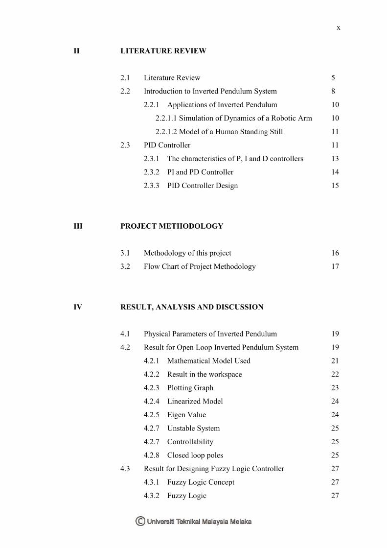
II LITERATURE REVIEW
2.1 Literature Review 5
2.2 Introduction to Inverted Pendulum System 8
2.2.1 Applications of Inverted Pendulum 10
2.2.1.1 Simulation of Dynamics of a Robotic Arm 10
2.2.1.2 Model of a Human Standing Still 11
2.3 PID Controller 11
2.3.1 The characteristics of P, I and D controllers 13
2.3.2 PI and PD Controller 14
2.3.3 PID Controller Design 15
III PROJECT METHODOLOGY
3.1 Methodology of this project 16
3.2 Flow Chart of Project Methodology 17
IV RESULT, ANALYSIS AND DISCUSSION
4.1 Physical Parameters of Inverted Pendulum 19
4.2 Result for Open Loop Inverted Pendulum System 19
4.2.1 Mathematical Model Used 21
4.2.2 Result in the workspace 22
4.2.3 Plotting Graph 23
4.2.4 Linearized Model 24
4.2.5 Eigen Value 24
4.2.7 Unstable System 25
4.2.7 Controllability 25
4.2.8 Closed loop poles 25
4.3 Result for Designing Fuzzy Logic Controller 27
4.3.1 Fuzzy Logic Concept 27
4.3.2 Fuzzy Logic 27
Page 11
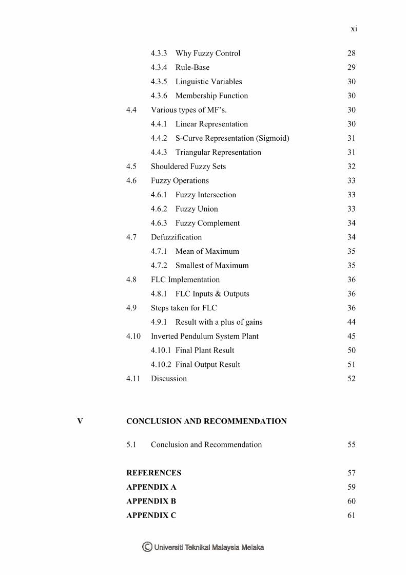
xi
4.3.3 Why Fuzzy Control 28
4.3.4 Rule-Base 29
4.3.5 Linguistic Variables 30
4.3.6 Membership Function 30
4.4 Various types of MF’s. 30
4.4.1 Linear Representation 30
4.4.2 S-Curve Representation (Sigmoid) 31
4.4.3 Triangular Representation 31
4.5 Shouldered Fuzzy Sets 32
4.6 Fuzzy Operations 33
4.6.1 Fuzzy Intersection 33
4.6.2 Fuzzy Union 33
4.6.3 Fuzzy Complement 34
4.7 Defuzzification 34
4.7.1 Mean of Maximum 35
4.7.2 Smallest of Maximum 35
4.8 FLC Implementation 36
4.8.1 FLC Inputs & Outputs 36
4.9 Steps taken for FLC 36
4.9.1 Result with a plus of gains 44
4.10 Inverted Pendulum System Plant 45
4.10.1 Final Plant Result 50
4.10.2 Final Output Result 51
4.11 Discussion 52
V CONCLUSION AND RECOMMENDATION
5.1 Conclusion and Recommendation 55
REFERENCES 57
APPENDIX A 59
APPENDIX B 60
APPENDIX C 61
Page 12
xii
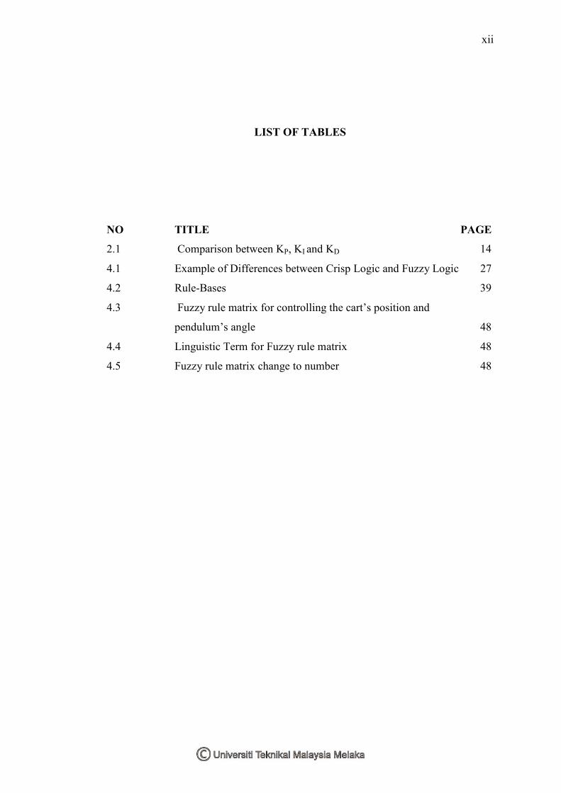
LIST OF TABLES
NO TITLE PAGE
2.1 Comparison between KP, KI and KD 14
4.1 Example of Differences between Crisp Logic and Fuzzy Logic 27
4.2 Rule-Bases 39
4.3 Fuzzy rule matrix for controlling the cart’s position and
pendulum’s angle 48
4.4 Linguistic Term for Fuzzy rule matrix 48
4.5 Fuzzy rule matrix change to number 48
Page 13
xiii
LIST OF FIGURES
NO TITLE PAGE
1.1 Inverted Pendulum used in this project 1
1.2 A full view of an Inverted Pendulum 2
2.1 Inverted pendulum system on a moving cart 10
2.2 A unity feedback system 12
2.2 Fuzzy Controller Block Diagram 13
2.3 A PID controlled system 14
3.1 Flow chart of project methodology 17
4.1 Free body diagram of inverted pendulum with cart 18
4.2 The input pulse for Inverted Pendulum System 19
4.3 The response for pendulum’s angle 20
4.4 Parameters needed 20
4.5 Command to subplot both graph in a figure 23
4.6 Plotting graph of angle and graph of position in a figure 23
4.7 Poles location for the eigen values 24
4.8 Unstable system 25
4.9 Closed loop poles 26
4.10 The unstable poles had been changed from the unstable
side (a) to the stable side (b) for all poles 26
4.11 Fuzzy Controller Block Diagram 29
4.12 Linear Representation 30
4.13 S-Curve representations (Sigmoid) 31
4.14 The inflection (flex or cross-over) point, where the domain value
is 50% true 31
4.15 Triangular representation 32
4.16 Shoulders of membership function 32
Page 14
xiv
4.17 The intersection 33
4.18 Union 33
4.19 SOM and MOM 35
4.20 Membership Function 40
4.21 Plant with gains 44
4.22 Output Plant with gains 44
4.23 Inverted pendulum open loop system plant 45
4.24 Inverted pendulum closed loop system plant with FLC 45
4.25 Inverted pendulum closed loop system plant with FLC and
PID controller 45
4.26 Inverted pendulum subsystem plant 46
4.27 Subsystem for subsystem 46
4.28 Fuzzy for position 48
4.29 Membership function for position 48
4.30 Fuzzy for angle 49
4.31 Membership function for angle 49
4.32 Full system plant with gains 50
4.33 Full system plant with gains and PID 50
4.34 Stable output for position 51
4.35 Stable output for angle 51
Page 15
xv
LIST OF APPENDIX
NO TITLE PAGE
A INVERTED PENDULUM 59
B FREE BODY DIAGRAM OF INVERTED PENDULUM 60
C EXAMPLES OF INVERTED PENDULUM SYSTEM IN
INDUSTRY 61
Page 16
CHAPTER I
INTRODUCTION
In this chapter, the background of the project study, the objective, as well as
the scope of the project and so on will be discussed.
1.1 Project Overview
Figure 1.1 Inverted Pendulum used in this project
An inverted pendulum is a physical device consisting in a cylindrical bar that
can free to oscillate to the left and right in upright position from a fixed pivot. The
Page 17
2
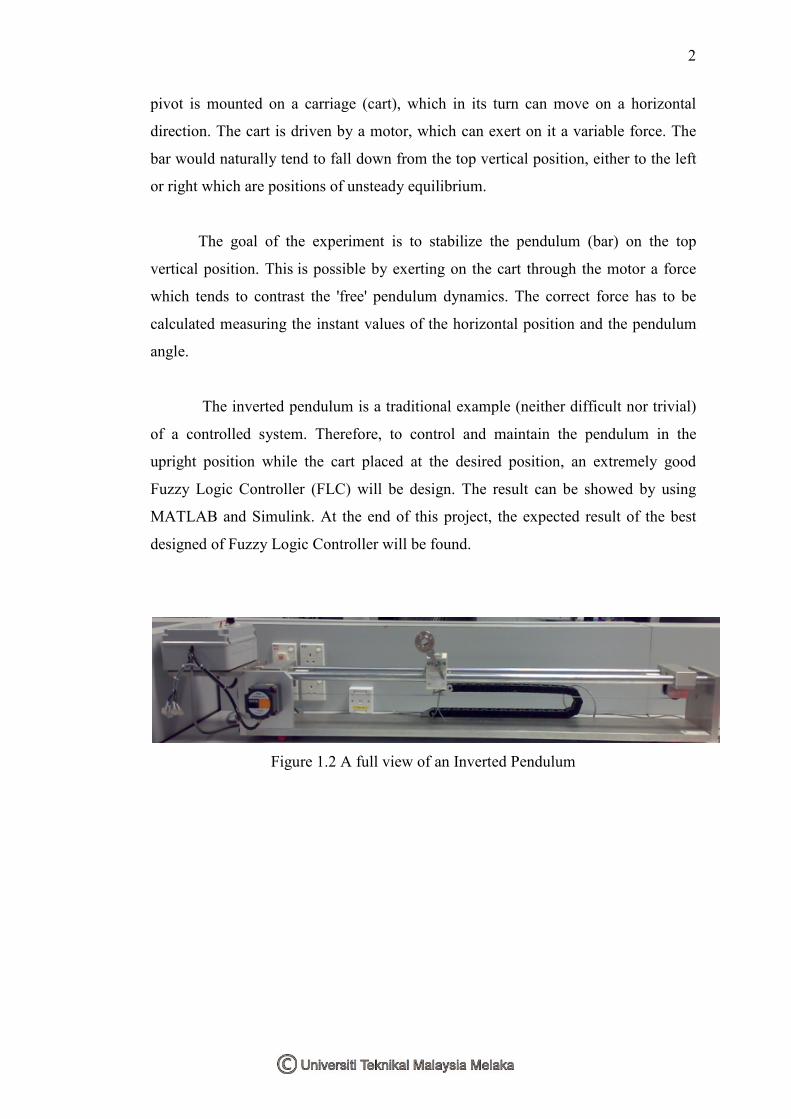
pivot is mounted on a carriage (cart), which in its turn can move on a horizontal
direction. The cart is driven by a motor, which can exert on it a variable force. The
bar would naturally tend to fall down from the top vertical position, either to the left
or right which are positions of unsteady equilibrium.
The goal of the experiment is to stabilize the pendulum (bar) on the top
vertical position. This is possible by exerting on the cart through the motor a force
which tends to contrast the 'free' pendulum dynamics. The correct force has to be
calculated measuring the instant values of the horizontal position and the pendulum
angle.
The inverted pendulum is a traditional example (neither difficult nor trivial)
of a controlled system. Therefore, to control and maintain the pendulum in the
upright position while the cart placed at the desired position, an extremely good
Fuzzy Logic Controller (FLC) will be design. The result can be showed by using
MATLAB and Simulink. At the end of this project, the expected result of the best
designed of Fuzzy Logic Controller will be found.
Figure 1.2 A full view of an Inverted Pendulum
Page 18
3
1.2 Problem Statement
Control of inverted pendulum system is recognized as a benchmark problem
for various controller designs and widely employed within laboratories for education
and research purposes. It is popular due to its simple setup and several interesting
features such as the instability, nonlinearity, and non-minimum phase characteristics.
The inverted pendulum system is an intriguing subject from the control point
of view due to their intrinsic nonlinearity. The problem is to balance the inverted
pendulum as well as it requires a continuous correction mechanism to stay upright
since the system is unstable, non-linear, and has non-minimum phase behavior as
mentioned.
1.3 Objective
The objectives of this project are to balance the pendulum on a moving cart
and to find a better control approach for the Inverted Pendulum System by using
Fuzzy Logic Controller.
i. To synthesis the mathematical model of the Inverted Pendulum.
ii. To understand the concept of Inverted Pendulum model.
iii. To design a Fuzzy Logic Controller (FLC) to control the system.
1.4 Scope of Project
The scope of this project are:
i. To study the concept of an inverted pendulum system.
ii. After that, a mathematical model of the inverted pendulum system is
derived using mathematical model which is created by K. Ogata
(1978).
iii. Then, Fuzzy Logic Controller system have to be studied and designed
before implementing and analyzing the project in MATLAB and
Simulink.
Page 19
4
1.5 Research Development
This project is about the nonlinear system. In that case, the first thing to be
learned is the concept of the nonlinear system. After that, the research should be
focusing on the concept of inverted pendulum system without any controller. Next is
to study how to derive the mathematical model of the inverted pendulum system
without any controller.
This nonlinear system needs a controller to control the system. The controller
suggested is Fuzzy Logic Controller. Therefore, the concept and how to design the
inverted pendulum system with the Fuzzy Logic Controller need to be learnt and
understand.
All of these derivations will be implemented in MATLAB and Simulink
program and the results need to be analyzed. For that reason, it is necessary to learnt
and really understand how to use the MATLAB commands and tools. It is really
important to be well understood in MATLAB and Simulink programming as this
project totally employs this MATLAB and Simulink program.
Then, with a plus of Proportional-Integral-Derivative (PID) controller to the
FLC, a new plus added controller will be designed to achieve the greater balance for
the inverted pendulum.
Page 20
CHAPTER II
LITERATURE REVIEW
In this chapter, discussion about the basic concept of inverted pendulum
system and FLC used for inverted pendulum system will be presented. It will consist
of detail explanation about the model, control approach, results and analysis.
2.1 Literature Review
The Switching Control for Inverted Pendulum System Based on Energy
Modification. [1] It is based on a modified energy such that the potential energy is
minimums in the upright position. This method of controlling the inverted pendulum
system has been derived by paying attention to the energy of pendulum. The model
of this inverted pendulum is proposed where there is a mass situated at the centre of
the pendulum’s pole and the cart dose not has wheels. The equation of motion is
derived by concerning the moment of inertia with respect to the pivot point, the mass
of the pole, the distance from the pivot to the centre of mass, the acceleration of
gravity, the acceleration of the pivot and the angle between the vertical and the
pendulum.
After considering the system with damping and how to control a system with
damping is figured out, a simulation is performed and the switching conditions were
lead and the control parameters were shown.
Page 21
6
Inverted pendulum system with the personified intelligent control which is
not based on the accurate mathematical model is presented. [2] It used a method that
can develop control laws directly by means of qualitative analysis and synthesis of
the plant. The inverted pendulum system is a multi-input single-output control
system consisting of four inputs; pole angle, change of the pole angle, cart position
and change of cart position and single output; control action. The prerequisite of
applying this control is to understand the physical structure and behaviour of the
controlled object as fully as possible. The model for this control is the inverted cart-
pendulum situated on a rail and driven by a single motor. The analysis done by
reduction of primary problem until small problems that can be solve. Then, the
equations obtained will be programmed in C language and the output can be seen
from the graph obtained.
The fuzzy logic controller for an inverted pendulum system does not require
a precise mathematical modelling of the system nor complex computations. [3]
Fuzzy control provides an easy solution to this problem as it is shown by the
derivation of the fuzzy linguistic rules and its function verified by computer
simulations. From this model of inverted pendulum system, the pendulum’s cart
receives an external force for balancing the pendulum provided by a permanent
magnet servo-motor mounted on the cart. The fuzzy logic controller changes the
human language to fuzzy language before it makes decision to control the system
and back to human language for further control action.
A Rule-Based Neural Controller for inverted pendulum system is presented.
It demonstrates how a heuristic neural control approach can be used to solve a
complex nonlinear control problem. [4] As well as to swing up the pendulum, the
controller is also required to bring the cart back to the origin of the track.
Specializing to the pendulum problem, the global control task is decomposed into
sub-tasks, namely, pendulum positioning and cart positioning. Accordingly, three
separate neural sub-controllers are designed to cater to the sub-tasks and their
coordination. The simulation result is provided to show the actual performance of the
controller. The advantage of this controller is it is able to implement dynamical
decisions and rules than just the static mapping actions. The simulation and analysis
Page 22
7
of the neural controller for the inverted pendulum system is done on a DECstation
using the software package Matlab.
Fuzzy Logic Controller for an Inverted Pendulum System was discussed
about the designing Fuzzy Logic Controller for Inverted Pendulum System. [5] The
case of fuzzy logic for the derivation of a practical control scheme for stabilizing the
inverted pendulum was presented in this paper. The Fuzzy Logic Controller required
only sensing the pole angular and cart position, and the implementation is simple. In
addition, the comparison of Fuzzy Logic Controller and conventional controller
(PID) was discussed too. In the end of this paper, the Fuzzy Logic Controller is ease
for implementation of this type of system and the best performance compare the
conventional controller (PID).
Fuzzy Logic Control of Vehicle Suspensions with Dry Friction Nonlinearity
is about designing and investigating the performance of Fuzzy Logic Controller
active suspensions on a linear vehicle model with for degrees of freedom without any
degeneration in suspension working limits. [6] This article is approach to new linear
combinations of the vertical velocities of the suspension ends as input variable. The
effectiveness of the Fuzzy Logic Controller for active suspension system was
discussed too. Decreasing the amplitudes of vehicle body vibration improves ride
comfort. In addition, body bounce and pitch motion of the vehicle were presented in
time domain when traveling over a ramp step road profile and in frequency domain.
The comparison between uncontrolled system and using the fuzzy logic controller
was discussed and also the performance and advantages and the improvement in ride
comfort.
Page 23
8
Fuzzy Control of Mechanical Vibrating System. Fuzzy logic is used to
control active hydro pneumatic suspension. [7] The ability of fuzzy logic were
discuss that could improve the reduction of the body acceleration caused by the car
body with road disturbance from uneven surface, pavement point and etc which are
act the tires of running cars. The Fuzzy Logic Controller used in this design has three
inputs are body acceleration, body velocity and body deflection velocity and one
output is desired actuator force. The simulation result is to compare the active and
passive suspension system is proposed to achieve both ride comfort and good
handling. Te aim was achieve by simulation result that the active suspension system
based on fuzzy logic controller shows the improved stability of the one-quarter-car
model.
Robust Speed Fuzzy Logic Controller for DC Drive was discussed the robust
speed control for a DC drive is considered. [8] The basis of the heuristic reasoning
the main features of the robust speed controller are supposed and the Fuzzy Logic
Controller that can control the DC Drive was designed. The comparison between PI-
controller and Fuzzy Logic Controller to control the DC Drive was approved. In the
end of this paper, the robust fuzzy speed control for a DC Drive was examined. The
Fuzzy Logic Controller is able to overcome the disadvantage of usual PI-controller
in sensitiveness to inertia vibration and sensitiveness to the range of reference speed
alteration.
2.2 Introduction to Inverted Pendulum System
In our daily life, at some time we may have tried to balance a brush, pen or
other object on your index finger or the palm of our hand. We have to constantly
adjust the position of the hand to keep the object upright. An inverted pendulum does
basically the same thing. However, it is limited in that it only moves in one
dimension, despite the fact that our hand could move up, down, sideways and other
directions.
Just as balancing with our hand, an inverted pendulum is an inherently
unstable system. Force must be properly applied to keep the system intact. To
Page 24
9
achieve this, proper control theory is required. The inverted pendulum is an
invaluable tool for the effective evaluation and comparison various control theories.
An inverted pendulum system consists of a thin rod (pole) attached at its
bottom of a moving cart. In a normal condition, a pendulum is stable when hanging
downwards, a vertical inverted pendulum is naturally unstable, and must be actively
balanced in order to remain upright, usually by moving the cart horizontally as part
of a feedback system.
The inverted pendulum system is essential in the evaluation and comparison
of various control theories. The inverted pendulum is used in simulations and
experiments to show the performance of different controllers (e.g. PID, State Space
and Fuzzy Controllers and else).
The inverted pendulum is a classic problem in dynamics and control theory
and widely used as benchmark for testing control algorithms (PID controllers, neural
networks, genetic algorithms and so on). Variations on this problem include multiple
links, allowing the motion of the cart to be commanded while maintaining the
pendulum, and balancing the cart-pendulum system. The inverted pendulum is
related to rocket or missile guidance, where thrust is actuated at the bottom of a tall
vehicle.
Another way that an inverted pendulum may be stabilized, without any
feedback or control mechanism, is by oscillating the support rapidly up and down. If
the oscillation is sufficiently strong in terms of its acceleration and amplitude, then
the inverted pendulum can recover from perturbations in a strikingly counterintuitive
manner.
There are many types of models for the inverted pendulum system. Some of
them are two-stage of inverted pendulum system, parallel inverted pendulum system,
rotational inverted pendulum system, bi-axial inverted pendulum system and many
more. In that case, there are also lots of controls approaches have been designed for
these various kinds of inverted pendulum system.