ROBT. L. ROWAN, JR., P.E. - ROBT. L. ROWAN & ASSOC., INC.
LARRY PHELPS - HESS OIL VIRGIN ISLANDS CORPORATION
MARK GERKIN - TENNESSEE GAS PIPELINE COMPANY
This report was prepared by the authors whose names appear thereon and is presented as part of the Reciprocating Machinery Conference sponsored by the Southern Gas Association Pipeline and Compressor Research Council. The report does not contain information resulting from the Southern Gas Association Pipeline and Compressor Research Council research program and reflects only the authors' opinions and viewpoints, which are not necessarily the same as those of the Southern Gas Association Pipeline and Compressor Research Council. Southern Gas Association Pipeline and Compressor Research Council does not extend warranties of any kind, either expressed or implied, with respect to the content of this report and assumes no liability or responsibility concerning the material contained herein, or any use which may be made thereof.
Control Of Crankshaft Distortion With An Adjustable Epoxy Chocking System
Revised September 03
Robt. L. Rowan & Assoc., Inc. · 3816 Dacoma · P.O. Box 920760 · Houston, Texas 77292-0760
Tel (713) 681-5811 · Toll Free (800) 231-2908 · Fax (713) 681-5815 Visit our website at www.rlrowan.com
The control of crankshaft distortion through proper original alignment and periodic maintenance
realignment has become a very important topic. Operators are finding it is cost effective to continue operating reciprocating compressors for 25 to 35 years. This subject can either be a planned part of maintenance scheduling or it will suddenly be thrust into the forefront with a catastrophic crankshaft failure. When a crankshaft breaks, there is always a good reason. They don't just break by themselves. In some cases the failure can be attributed to a fault in the crankshaft material, or to an operations induced overload, but in the majority of failures being seen today, improper alignment causes a fatigue type failure. Flexing of the crankwebs, more than manufacturer's tolerances, over time, with enough stress reversals, can and does lead to cracks and breakage. With today's knowledge and technology, this type of crankshaft failure can be controlled more easily than the other two modes of failure mentioned. Since we are going to be talking about crankshaft distortion or alignment, let's identify the major influences. The first is the alignment of the frame and mainframe saddles. Also very important is the influence on crankshaft alignment from the horizontal compressor cylinders and associated piping. Finally, the conditions of the bearings have to be considered. Bearing condition is often overlooked when crankshaft alignment is being checked by use of crankweb distortion gauges. Before correcting a poor crankshaft alignment, you need to know if changing the bearings should make the correction, or if aligning the frame should make it.
From the above, we can summarize that a properly aligned reciprocating gas engine is one where:
a) The frame is level b) The gas compressor cylinders and piping are not going to distort the frame under load c) The bearings are good, and have proper clearance d) The crankweb deflections are within manufacturers tolerances e) The anchor bolts are tight enough to prevent frame movement
With regard to the subject of acceptable tolerances, some of the older O.E.M. manuals may say the deflections should be within .001 inches. What is not said is whether the tolerance is a plus or minus, or the cumulative effect at adjacent throws. A +.001 at #3 and a -.001 at #4 might appear to be within tolerance. Conventional wisdom today says this should be treated as .002. The rate of change and reversal from a crankweb open position to a crankweb-closed position must also be taken into consideration.
When taking web deflection, it is important to have a consistent procedure so results can be compared. While how to take proper readings is a subject in itself, important considerations are: a calibrated distortion gauge; size and smoothness of the "ping" indentation for the gauge; temperature of the frame; where the distortion gauge is zeroed; and repeatability of results. Don't make a hasty decision based on one set of readings. The subject of crankweb deflections, as a measure of the alignment condition of a crankshaft and frame, is further complicated by other factors. One of these factors is the question of hot running alignment versus the cold alignment. Unfortunately, we have to initially align the machine in a cold, unloaded condition. Naturally this changes as the machine heats up and grows thermally and is subjected to dynamic loads. We try to estimate what the hot alignment condition is by shutting down the machine and taking deflections with the frame warm, but in a cooling cycle and without any dynamic influences. Certainly the popularity of an adjustable chocking system is because changes in the frame alignment can be made quickly so a best operating condition alignment results.
Control Of Crankshaft Distortion With An Adjustable Epoxy Chocking System
Revised September 03
Robt. L. Rowan & Assoc., Inc. · 3816 Dacoma · P.O. Box 920760 · Houston, Texas 77292-0760
Tel (713) 681-5811 · Toll Free (800) 231-2908 · Fax (713) 681-5815 Visit our website at www.rlrowan.com
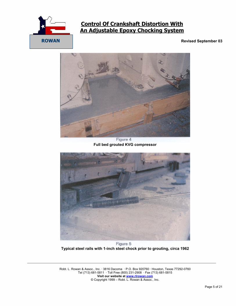
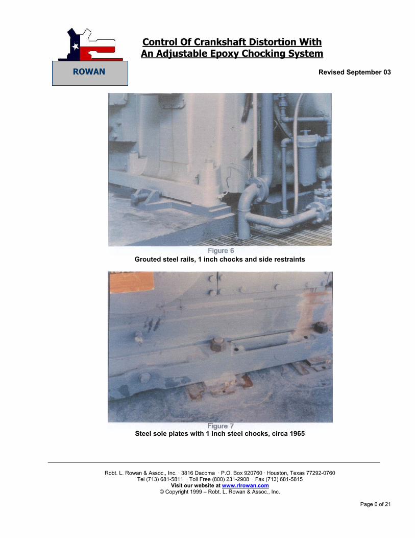
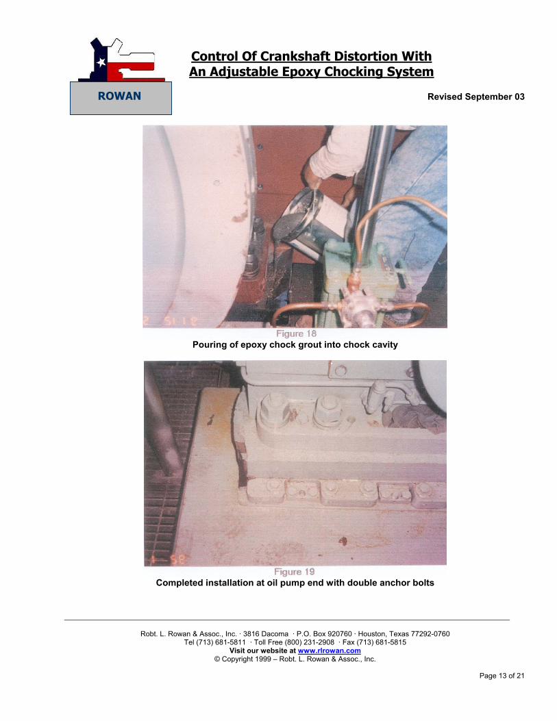
Another important factor is the clamping force of the anchor bolts. We have learned through experience that much higher tightening torque is required to hold the frames in place than the older O.E.M. manuals recommended. If a crankweb deflection check is made, with the anchor bolts minimally tight, it is possible to get good readings. However, if the machine has a very stiff frame, as many do, and the minimal torque on the anchor bolts allows the frame, under load, to move vertically or horizontally say .005 to. 010 inches, the running deflections will be different from the cold, static deflection readings. It is not uncommon in the field to see such movement, yet the operator feels the machine is within crankweb deflection tolerances. Some people have been reluctant to tighten anchor bolts since the grout or chock may have worn down and such tightening could pull the frame down, out of alignment. Again, the use of an adjustable chocking system allows proper clamping force to be re-established with the frame at the proper elevation. Instead of having to live with a bad situation, the operator is given a tool to manage the situation. With the above several points in mind, let's review the evolution that has developed over the past 35 years from full-bed grouting of the entire machine frame to the modern adjustable chocking systems that fit under the frame at each anchor bolt. The following pictures (slides) will illustrate the development and history of gas compressor support systems.
A.) Full bed grouting 1) Cementitious grout - 1940's 2) Epoxy Grout - 1957 B.) Steel rails with 1" steel chocks - 1960's C.) Steel sole plates with 1" steel chocks - 1960's D.) First poured in place epoxy chock - 1964 E.) Steel sole plate with dual steel chocks and .030
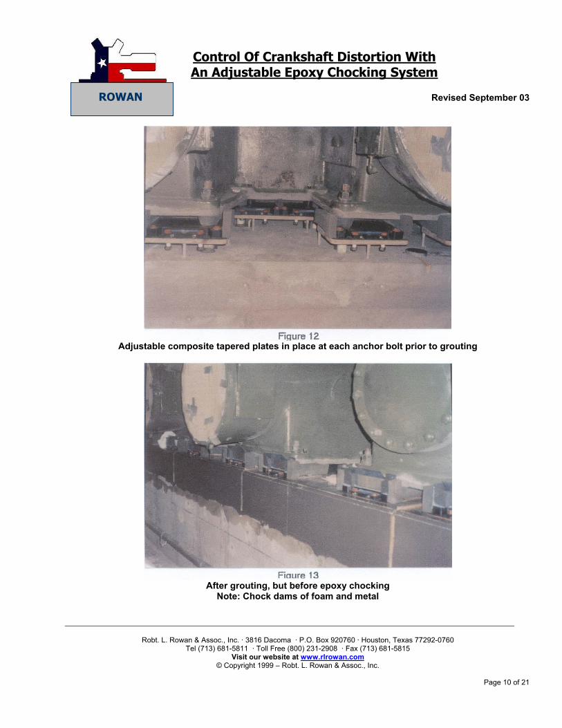
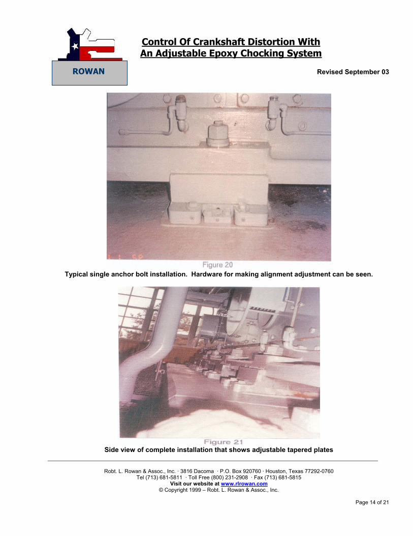
shim pack - 1974 F.) Poured in place epoxy chocks combined with
adjustable composite tapered plates - 1988
Control Of Crankshaft Distortion With An Adjustable Epoxy Chocking System
Revised September 03
Robt. L. Rowan & Assoc., Inc. · 3816 Dacoma · P.O. Box 920760 · Houston, Texas 77292-0760
Tel (713) 681-5811 · Toll Free (800) 231-2908 · Fax (713) 681-5815 Visit our website at www.rlrowan.com
Published data,¹ the latest of which is Report No. 89-3 sponsored by PCRC², have investigated the
effect on crankshaft distortion of various support systems from full bed grouting through steel chocks and epoxy chocks. The common thread is that chocking systems, either steel or epoxy, favor the crankshaft by reducing thermal humping and an adjustable system is preferable to a fixed system so the optimum alignment in a hot running condition can be achieved. A further advantage of an adjustable system is alignment corrections can be made where the misalignment is caused by foundation problems.
We all have seen full bed grouted machines set on the original epoxy grout over 30 years still operating in
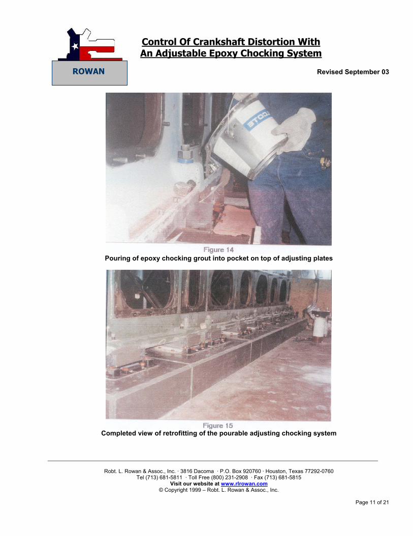
proper alignment. That is attributable to good stable concrete foundations. The next station down the line may have machines that have been regrouted several times with the newer epoxy chocking systems and have misalignment problems or even crankshaft breakage. As we investigate these conditions as engineers, we find foundation related misalignment causes quite often, and the traditional epoxy chocking systems that are not adjustable, can't compensate for the resulting elevation changes. Certainly the trend in the industry towards putting new machines on adjustable chocking systems is a recognition that foundation related problems can and do develop over time. Two of the most significant technological advances the gas compressor industry has seen are the invention of a dependable adjustable pourable epoxy chocking system and unique concrete foundation repair techniques. It would be nice if all bad foundations could be replaced, but this is just not economically possible. However, coupling a foundation repair with an adjustable pourable epoxy chocking system has allowed the useful life of gas compressors to be extended for many more years. The subjects of modern day foundation rehabilitation and anchor bolt upgrading are important in their own right. They also are important in the proper application of an adjustable pourable epoxy chocking system. To illustrate the above, the following pictures (slides) will show how an adjustable pourable epoxy chocking system can be retrofitted to an old machine, in connection with foundation rehabilitation, and also how it can easily be installed under new machines. A brief explanation of how field adjustments are made will also be illustrated.
Control Of Crankshaft Distortion With An Adjustable Epoxy Chocking System
Revised September 03
Robt. L. Rowan & Assoc., Inc. · 3816 Dacoma · P.O. Box 920760 · Houston, Texas 77292-0760
Tel (713) 681-5811 · Toll Free (800) 231-2908 · Fax (713) 681-5815 Visit our website at www.rlrowan.com
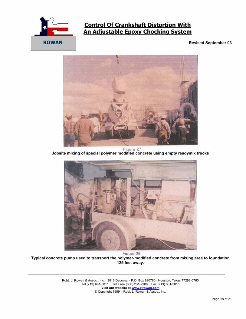
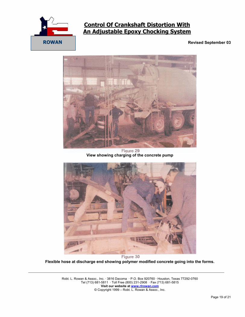
The Tioga Gas Plant first came on line in 1954 with seven low-pressure compressors with 10-psi suction to 800-psi discharge, through three stages of compression. Through the years, the plant was operated by several different companies with different operating philosophies, which resulted in varying conditions of the plant equipment. This condition was most especially prevalent with the 2000 hp Clark HLA 8, low-pressure compressors. Amerada Hess made a conscious decision to improve and upgrade the condition of the equipment after take-over of the plant during the summer of 1988. The Clark foundations, which had been repaired or replaced many times through the years, had almost as many different designs and grout types as there were repairs. Designs included full bed grout, epoxy chocks, and steel sole plates with shims. A consulting service was brought in to assess the situation and make recommendations on repairs. Conclusions were that the Clark compressors C1E and C1F were by far the worst, but C1C and C1D would be the most economical to repair first because of their better mechanical condition. A multi-year plan was laid out to repair foundations as required, replace grout caps, and install an adjustable chock system. C1C and C1D were planned for the summer of 1989, C1F in 1990, and C1E in 1991. The C1C compressor had cracks in the foundation block, cracks in the grout, and cracks in the epoxy chocks. The compressors were removed from the engine and the complete engine was removed from the foundation by jacking it up and sliding it onto a metal frame built for that purpose. The foundation was found to have oil contaminated cement all the way to basement floor level. The foundation was replaced using the original rebar design and high early cement. The grout used was a high modulus epoxy grout and an adjustable pourable epoxy chocking system was installed. The C1D compressor that was completed at the same time as the C1C, August 1989, had cracks in the grout cap and in the epoxy chocks. The engine was jacked up in place and the top eighteen inches were removed from the foundation. The foundation was repaired with fast setting polymer modified concrete, the grout poured using a high modulus epoxy grout, and an adjustable pourable epoxy chocking system installed.
The C1F compressor was planned for 1990, however a thrown counterweight on the C1A compressor changed those plans. The damage from the thrown counterweight was mostly limited to the upper frame on the flywheel end. A close inspection of the engine revealed that there was a significant hump on the opposite end of the engine. This compressor, which had been regrouted some five years earlier with a full bed grout, had developed a classic thermal hump. The engine was completely disassembled and removed from the foundation. The foundation was chipped down to good concrete and brought back to elevation with fast setting polymer modified concrete, regrouted with a high modulus epoxy grout, and an adjustable pourable epoxy chocking system installed. The engine frame was sent out for repairs and included a remachining of all critical areas. The lower frame was set and line bored on location to insure best possible alignment. The C1E compressor was placed in front of the C1F compressor for 1991 due to several indicators indicating that it was moving on its foundation. This compressor had its complete foundation replaced in 1987 and was setting on steel chocks with shims. An adjustment was made in June of 1990 that enabled it to operate until December of that year without damaging the crankshaft. The foundation that was severely cracked had oil-contaminated cement all the way down. This foundation repair started off with a redesign of the rebar that included much more rebars and rebar in the grout cap. Because of the cold weather and the lack of a close batch plant, this entire foundation was poured with fast setting polymer modified concrete. The grout cap was poured with a high
Control Of Crankshaft Distortion With An Adjustable Epoxy Chocking System
Revised September 03
Robt. L. Rowan & Assoc., Inc. · 3816 Dacoma · P.O. Box 920760 · Houston, Texas 77292-0760
Tel (713) 681-5811 · Toll Free (800) 231-2908 · Fax (713) 681-5815 Visit our website at www.rlrowan.com
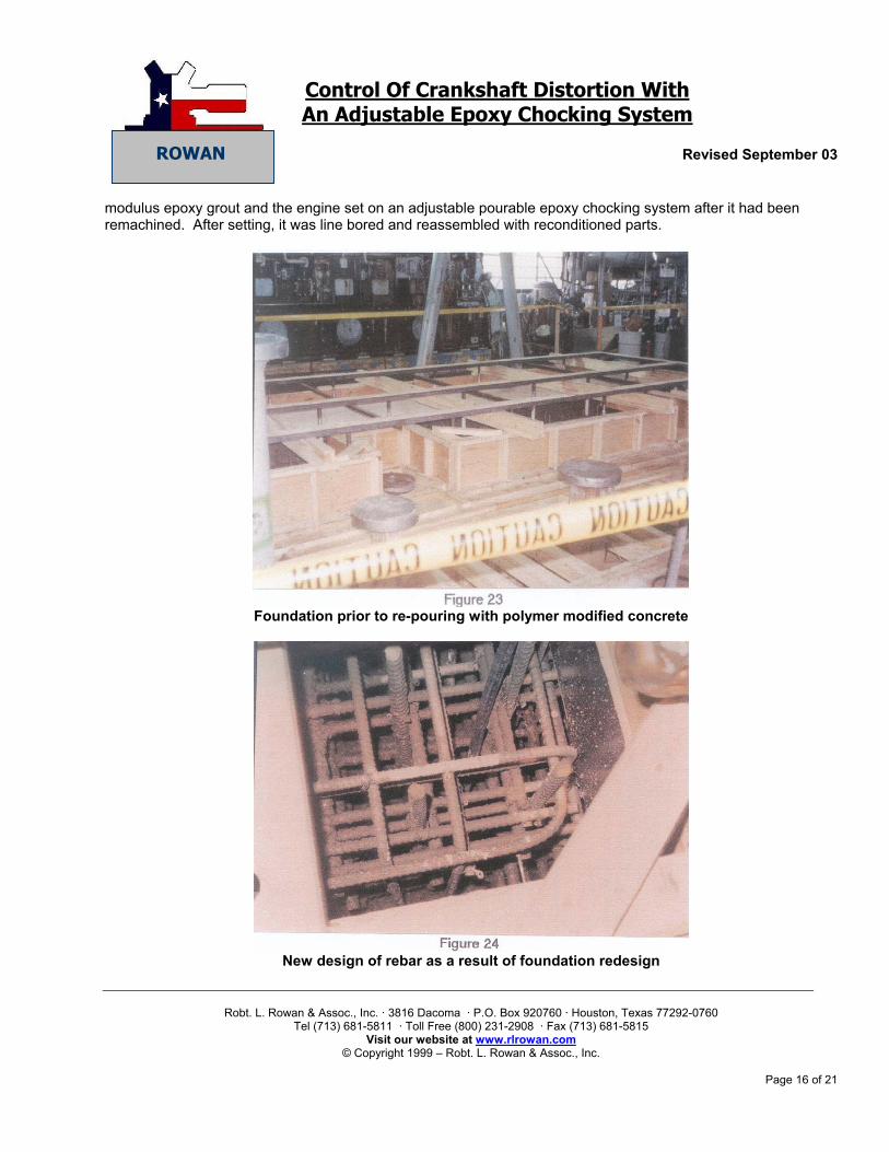
modulus epoxy grout and the engine set on an adjustable pourable epoxy chocking system after it had been remachined. After setting, it was line bored and reassembled with reconditioned parts.
Foundation prior to re-pouring with polymer modified concrete
New design of rebar as a result of foundation redesign
Control Of Crankshaft Distortion With An Adjustable Epoxy Chocking System
Revised September 03
Robt. L. Rowan & Assoc., Inc. · 3816 Dacoma · P.O. Box 920760 · Houston, Texas 77292-0760
Tel (713) 681-5811 · Toll Free (800) 231-2908 · Fax (713) 681-5815 Visit our website at www.rlrowan.com
The C1F compressor is presently being replaced with a new compressor and will be used as spare parts
for the remaining Clark compressors. In summary of the adjustable pourable epoxy chocking system installation and foundation repairs, all indicators are showing positive influences. The attached lube oil analysis summary, which summarizes all wear metals, shows positive influences on all except for the C1D machine. This machine on a recent annual inspection revealed lubrication problems on the power cylinders.