5

A. Z-source Inverter Control
To design control system, a transfer function of the
dynamic properties of the Z-source inverter is to be
derived. The state space average model of the Z-source
inverter is used to get the desired converter transfer
function. We can simplify the Z-source coupled single-
phase inverter as shown below in Fig.1. In Fig.1, S2 and S1
are replaced by the inverter and the input diode
respectively. The shoot-through duty is cycle is defined by
the S2 duty cycle, Do. In the Z-source network, there are
two dynamic states[1]. During shoot-through state switch,
S1 will be open, and S2 will be closed, that makes sure the
input energy will not be transferred to the load. There will
be the distribution of the energy transfer between inductors
and capacitors in Z-network. The actual power transfer
will happen during non-shoot-through states. The control
strategy of the shown in Fig. 2 and 3. The control to
voltage transfer function of the Z-network is given by
𝐺𝑉𝐶𝑑(𝑠) = 𝑉𝑐𝐷𝑂
(1)
=𝑉𝐷(2𝑉𝑐− 𝑉𝑑𝑐−𝑅𝐼𝐿𝑜𝑎𝑑)+(𝑟+𝑅)(𝐼𝐿𝑜𝑎𝑑−2𝐼𝐿)−𝑠𝐿(2𝐼𝐿− 𝐼𝐿𝐿𝑜𝑎𝑑)𝑠2𝐿𝐶+𝑠𝐶(𝑅+𝑟)+(𝑉𝐷)2
(2)
The complete transfer function can be written by using
the equations (1) and (2).
T(s) = 𝐺𝐶(𝑠). 𝐻(𝑠). 𝑉𝑐𝐷𝑂 . 𝐷𝑂𝑉𝑚 = 2𝑉𝑡𝑟𝑖 . 𝐺𝐶(𝑠). 𝐻(𝑠). 𝐺𝑉𝐶𝑑(𝑠) (3)
The plot of the T(s), loop transfer function is plotted to
show the unity gain and uncompensated loop. At unity
gain, it has the crossover frequency of 230 Hz and phase
margin of ten degrees. To improve the overall bandwidth
and phase margin of the compensated loop, the PID
compensator is designed which is shown below.
GC(s) = GCo (1+ sωz1).(1+ sωz2)s.(1+ sωp)
(4)
The compensator gain GCo is given by
GCo = 1|𝐺𝐶(𝑠).𝐻(𝑠).𝐺(𝑠).𝑘𝑠ℎ𝑜𝑜𝑡−𝑡ℎ𝑟𝑜𝑢𝑔ℎ| (5)
Fig. 4. shows the bode plots of the loop transfer function.
Fig. 1 Equivalent circuit of Z source network
Fig. 2 Control strategy of Z source network
Fig.3. Block diagram of a voltage controller
Fig. 4. Bode plots of loop transfer function
1 10 102
103 104[Hz]
1 10 102
103 104[Hz]
2606

B. INTEGRATED CONTROL SYSTEM FOR Z-SOURCE BASED
SINGLE PHASE INVERTER
In the previous section, we have designed the
compensators for the standalone Z-source network which
generates the shoots-through pulses and compensator for
the single phase inverter which regulates the input side of
the single-phase inverter. To regulate the input voltage of
the PV panel with Z-source network and single phase
inverter both controls are incorporated and it is shown in
Fig.5.
Fig. 5 Complete Control block for Z source network
Both the pulses, i.e., the shoot- through pulses generated
for the Z-source network and pulses for the PV voltage
control is mixed through integrated pulse generator which
is shown in Fig. 6. Both the shoot- through(ST) and
conventional pulses are sent through OR gate to generate
the required pulses for the operation.
Fig. 6 Mixing gate signals
C.Kalman Filter
Kalman Filter is a state estimator or observer. However,
the uniqueness of Kalman Filter is its estimation in noisy
conditions or estimating noisy inputs. It uses the
probability of noise covariance and estimates the state
based on its linear behaviour of the state. Fig. 8 shows the
general block diagram of the Kalman Filter.
Fig. 6. Block diagram of a Kalman Filter
If 𝑥�̂� is the state at iteration t and 𝑧𝑡 is the measured
signal at t, following are the Kalman filter equations[12],
(i)Time Update – (Prediction state) 𝑥𝑡−̂ = 𝐴 𝑥𝑡−1̂ + 𝐵𝑢𝑡−1 (6)
𝑧𝑡− = 𝐴𝑧𝑡𝐴𝑇 + 𝑄 (7)
Here process noise covariance is Q, 𝑥𝑡−̂ be the state
estimate at iteration t given by the results from previous
iterations, 𝑥�̂� be the state estimate at iteration t given by
the output measurement 𝑦𝑡−̂ , 𝑧𝑡−̂ be the priori error
covariance and 𝑧𝑡 or 𝑧𝑡− be the posteriori error
covariance. A & B are constants.
(ii)Measurement Update – (Correction State) 𝐾𝑡 = 𝐶𝑇𝑍𝑡−(𝐶𝑍𝑡−𝐶𝑇 + 𝑅)^ − 1 (8)
𝑥�̂� = 𝑥𝑡−̂ + 𝐾𝑡(𝑦𝑡 − 𝐶 𝑥𝑡−̂) (9)
𝑧𝑡 = 𝑧𝑡(1 − 𝐾𝑡𝐶) (10)
R is the measurement noise covariance, 𝐾𝑡is the Kalman
gain and C is constant. The above equations represent
Linear Kalman filter implementation for a linear discrete
system. The time update predicts next state estimate and
error covariance. The estimates are then fed back to
measurement update which acts as a corrector and corrects
the estimated values. As the above cycle takes place in
multiple iterations in turns, the noises are reduced and the
error covariance 𝑧𝑡 becomes closer to zero.
D. The proposed Kalman Filter based MPPT
The Power versus Voltage characteristics of PV array is a
convex function where the peak point is called maximum
power point. This can be expressed using the following
equation, 𝑉[𝑛 + 1] = 𝑉[𝑛] + 𝑀 ∆𝑃[𝑛]∆𝑉[𝑛] (11)
Here, M is the step size and ∆𝑃[𝑛]∆𝑉[𝑛] is the instantaneous
power slope of the PV module. By using the Kalman gain
both the error covariance and the estimated voltage are
corrected to �̂�𝑎𝑐𝑡[𝑛] and 𝐻[𝑛] in measurement update
state. However, the feedback voltage �̂�𝑎𝑐𝑡[𝑛 + 1]− and
error covariance 𝐻[𝑛 + 1]− is estimated by the time
update equations.
(i)Time Update – (Prediction state) �̂�[𝑛 + 1]− = �̂�[𝑛] + 𝑀 ∆𝑃[𝑛]∆𝑉[𝑛] (12) 𝐻[𝑛 + 1]− = 𝐻[𝑛] + 𝑄 (13)
2607

(ii)Measurement Update – (Correction State) 𝐾[𝑛] = 𝐻[𝑛]−(𝐻[𝑛]− + 𝑅)− (14) �̂�𝑎𝑐𝑡[𝑛] = �̂�𝑎𝑐𝑡[𝑛]− + 𝐾[𝑛]( Vref [n] - �̂�𝑎𝑐𝑡[𝑛]− )
(15) 𝐻[𝑛] = ( 1 – K[n]) 𝐻[𝑛]− (16)
The below figure shows the flow chart of proposed KF
based MPPT. After the measurement of PV voltage and
current at each nth state, the system computes the power
and the difference in voltage and power. Using these
measurements, the system executes time and measurement
update stage. The estimated voltage is used to calculate
duty cycle of the single phase inverter. These equations
and measurements iterates continuously in a cycle.
Fig. 7 KF based MPPT
III. RESULTS
Theoretical advantages of the Kalman Filter based Z-
source inverter is verified by implementing in the
MATLAB / SIMULINK. The simulation results present
the analysis and performances of Kalman based Z-source
and P&O based Z-source Inverter. The configuration of
PV panel used for the simulation is shown in the below
table.
Table 1:Electrical Specifications of Test PV panel
Parameters Values
Max. Power Voltage 17.9 V
Max. Power Current 0.51 A
Open Circuit Voltage 22.5 V
Short Circuit Current 0.61 A
Fig. 8 KF vs P&O simulation
Fig. 8 shows how the Kalman filter is faster compared to
the P&O algorithm. We can see that Kalman took 5ms to
track the maximum power. However, P&O took around
200ms to track. Fig. 8 also shows even during the sudden
changes in the irradiance Kalman filter has been highly
efficient in tracking, whereas P&O algorithm failed to see
sudden changes.
Fig. 9 Power loss comparison
Fig. 9 shows the power loss comparison between the
power regulator and Z-source inverter. The experimental
setup for the proposed system for a photovoltaic system is
shown in Fig. 10.
Fig.10 Experimental setup
2608
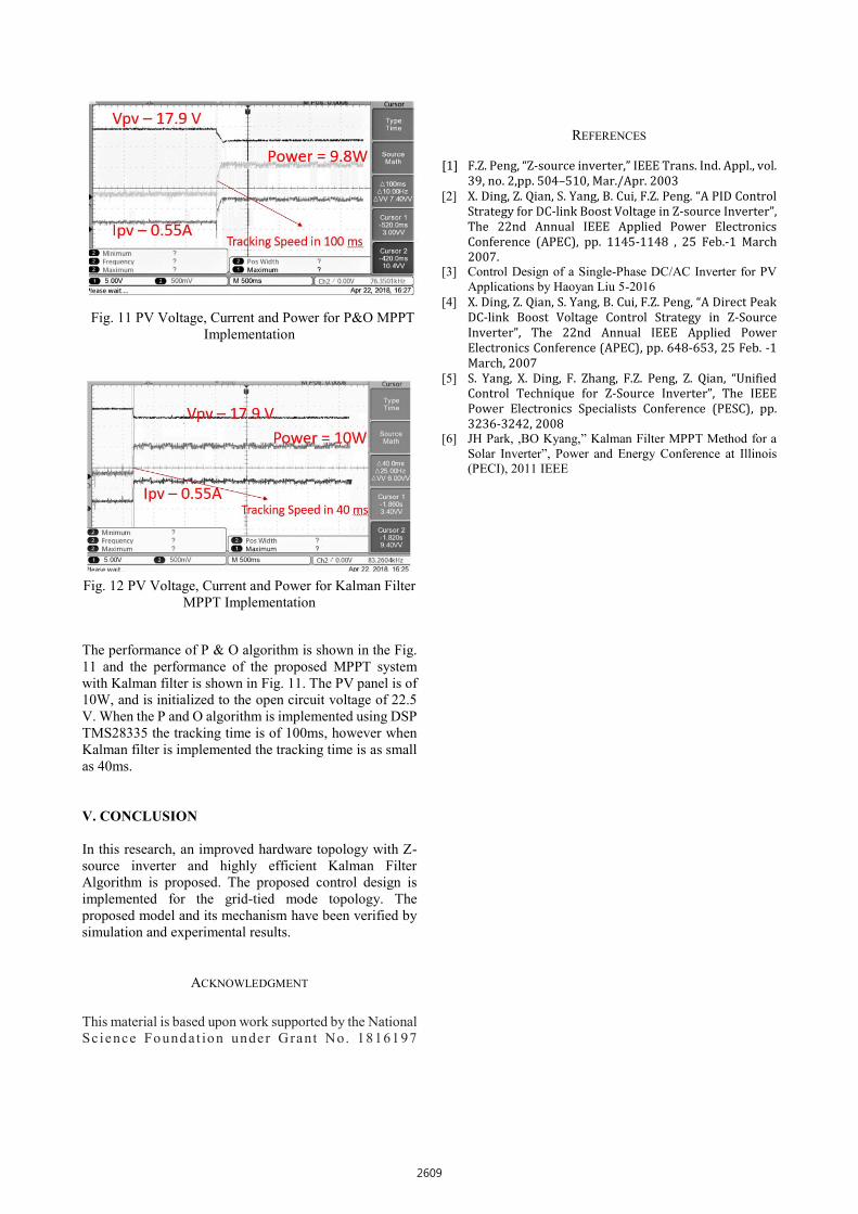
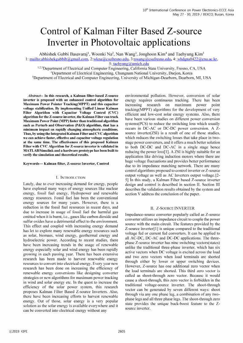
Fig. 11 PV Voltage, Current and Power for P&O MPPT
Implementation
Fig. 12 PV Voltage, Current and Power for Kalman Filter
MPPT Implementation
The performance of P & O algorithm is shown in the Fig.
11 and the performance of the proposed MPPT system
with Kalman filter is shown in Fig. 11. The PV panel is of
10W, and is initialized to the open circuit voltage of 22.5
V. When the P and O algorithm is implemented using DSP
TMS28335 the tracking time is of 100ms, however when
Kalman filter is implemented the tracking time is as small
as 40ms.
V. CONCLUSION
In this research, an improved hardware topology with Z-
source inverter and highly efficient Kalman Filter
Algorithm is proposed. The proposed control design is
implemented for the grid-tied mode topology. The
proposed model and its mechanism have been verified by
simulation and experimental results.
ACKNOWLEDGMENT
This material is based upon work supported by the National
Sc ience Foundat ion under Grant No. 1816197
REFERENCES
[1] F.Z. Peng, “Z-source inverter,” IEEE Trans. Ind. Appl., vol.
39, no. 2,pp. 504–510, Mar./Apr. 2003
[2] X. Ding, Z. Qian, S. Yang, B. Cui, F.Z. Peng. “A PID Control Strategy for DC-link Boost Voltage in Z-source Inverter”, The 22nd Annual IEEE Applied Power Electronics
Conference (APEC), pp. 1145-1148 , 25 Feb.-1 March
2007. [3] Control Design of a Single-Phase DC/AC Inverter for PV
Applications by Haoyan Liu 5-2016
[4] X. Ding, Z. Qian, S. Yang, B. Cui, F.Z. Peng, “A Direct Peak DC-link Boost Voltage Control Strategy in Z-Source Inverter”, The 22nd Annual IEEE Applied Power
Electronics Conference (APEC), pp. 648-653, 25 Feb. -1
March, 2007
[5] S. Yang, X. Ding, F. Zhang, F.Z. Peng, Z. Qian, “Unified Control Technique for Z-Source Inverter”, The IEEE
Power Electronics Specialists Conference (PESC), pp.
3236-3242, 2008 [6] JH Park, ,BO Kyang,” Kalman Filter MPPT Method for a
Solar Inverter”, Power and Energy Conference at Illinois
(PECI), 2011 IEEE
2609


