31
CONTROL VALVE ADVANCED DIAGNOSTICS WITH FOUNDATION FIELD BUS POSITIONER K.N.Narayanan P.Ramakrishnan Sr.Manager SAMSON CONTROLS PVT.LTD.

CONTROL VALVE ADVANCED DIAGNOSTICS WITH
FOUNDATION FIELD BUS POSITIONER
K.N.Narayanan
P.Ramakrishnan
Sr.Manager
SAMSON CONTROLS PVT.LTD.

Positioner type 3730-5
Product management
Jens Bargon / V42
Smart Valve Positioner with
diagnostic functions

Communication of Foundation Field bus
ccccccccccccccccc
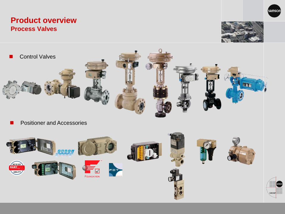
Control Valves
Product overview Process Valves
Positioner and Accessories

Control Valves are the “Final Control
element”
in every process plant
They are subject to wear and tear
and therefore an important target
for asset management and predictive
maintenance procedures
Control Valves & FF Smart Positioners
Smart positioners with integrated diagnostic
functions and FOUNDATIONTM Fieldbus technology
deliver optimal solution

· 6
Life Cycle Costs (Total Cost of Ownership)
Calculated with SAMSON Programme
Standard control valve for PN (Class 300) cast steel 1.0619/A216 WCC, equipped
with pneumatic actuator and FF smart positioner
15 years of useful lifetime
1 manly hour repair time
Repair on site

Smart diagnosis for predictive / proactive
maintenance
Smart Positioners with advanced diagnostic features offer us information , enabling
fault detection and analysis on line.
This acts as a powerful tool for predictive maintenance.
Integrated statistics analyses & provide remedies for the fault.
Problems like , air leakage, actuator leakage , packing friction change,
Diaphragm failure, process deviation etc . Can be addressed by the Positioner.
Information available can be utilised for preventive ,predictive or proactive maintenance.
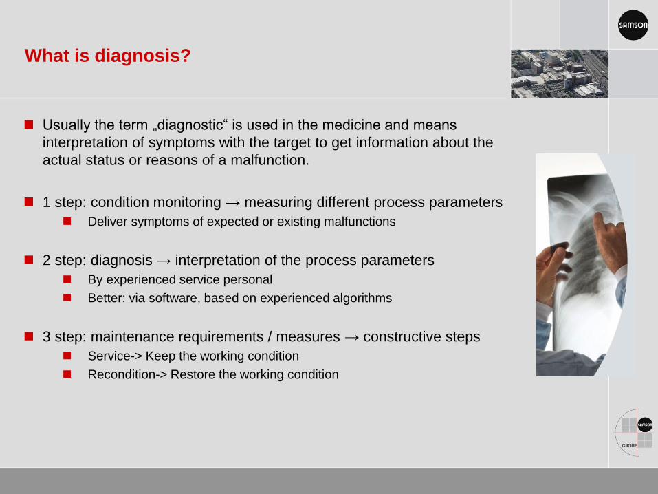
Usually the term „diagnostic“ is used in the medicine and means
interpretation of symptoms with the target to get information about the
actual status or reasons of a malfunction.
1 step: condition monitoring → measuring different process parameters
Deliver symptoms of expected or existing malfunctions
2 step: diagnosis → interpretation of the process parameters
By experienced service personal
Better: via software, based on experienced algorithms
3 step: maintenance requirements / measures → constructive steps
Service-> Keep the working condition
Recondition-> Restore the working condition
What is diagnosis?
Samson/KNN/ 13th July 2012
Example of Diagnostic Functions
Travel histogram
(The histrogram provides information about where the valve mainly works during its
service life and if it shows a recent trend towards changes in its working range.)
Hysteresis test
(It displays changes in friction. The positioner generates a message when the
results of the hysteresis test pinpoint to „Friction“ or „External leakage“.
Trend of travel end position
(This feature detects fluctuating zero points or creeping zero point shifts due to
seat and plug wear or dirt between seat and plug.
Steady-state Drive Signal Diagram
It allows changes in the supply pressure or leakage in the pneumatics to be
detected.
Cycle counter histogram
(It provides a statistical analysis of the cycles and also information on the dynamic
stress of a bellows and packing.
Dynamic stress factor: percentage of the stress of a bellows and packing. Error
message „External leakage—maybe to be expected soon“ is generated if the
dynamic stress factor exceeds 90%.

General requirements
Diagnostics should be realized without any additional sensor systems
The valve is in controlled operation and the process may not be to interrupted!
Histograms allow to evaluate the valve travel [x], the set point deviation [e]
and the valve cycle counter as an automatic function without any setup in the
background
The valve signature function allows …
to detect possible changes in friction
to detect possible changes in the supply pressure or maybe leakages in the pneumatic supply
The Final position trend monitoring function allows to detect a fluctuating or creeping
zero point due to seat & plug wear or material between seat and plug
Dynamic Stress factor to monitor the stuffing box
Partial Stroke Test for on/off applications
Leakage sensor to detect inner leakages between seat & plug
Monitoring functions during the running process

Drive signal y
ccccccccccccccccc
Automatic y recording (monitor-function steady state) , assigning to a valve travel
class and averaged (long- and short-term)
Test function, test started by means of (E)DD, DTM or TROVIS-VIEW…
determines y at fixed travel positions, over the entire travel range (hysteresis)
Message generation
Reference with time stamp

Drive signal y
ccccccccccccccccc
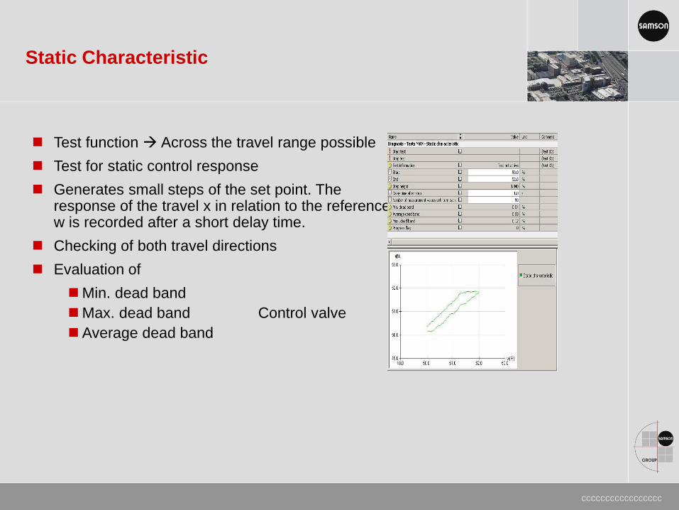
Static Characteristic
ccccccccccccccccc
Test function Across the travel range possible
Test for static control response
Generates small steps of the set point. The response of the travel x in relation to the reference w is recorded after a short delay time.
Checking of both travel directions
Evaluation of
Min. dead band
Max. dead band Control valve
Average dead band

Storing last 30 messages in FF Positioner
ccccccccccccccccc

Total travel counter
ccccccccccccccccc

Temperature monitor
ccccccccccccccccc

Cycle counter histogram
ccccccccccccccccc
Counting of cycle frequency and
detecting of highness of span
Assigning of the travel performed
in the cycle to a determined
valve travel class
Number of measurement values
Average calculation
Long- and short-term diagram
Differentiation (stuffing box)
Self-adjusting
Adjustable packing
Bellows seal
Others max. cycle counter limit
Dynamic stress factor
Percent indication
Message generation

The operator needs to differentiate the
stuffing box! The corresponding values are
based on experiences in the SAMSON
development department!
Self-adjusting
Adjustable packing
Bellows seal
Other adjustable threshold
Dynamic stress factor [%]
The rate of wear of the selected stuffing box
will be calculated
New: 0%
Statistical defect 100%
Above 90% a message will be
generated
Long-term histogram
Cycle counter details

Data logger
ccccccccccccccccc
Storage of the last 100 values of x, w, e and y in the positioner
Adjustable sampling rate
Storing possibilities
Permanent (FIFO)
Trigger condition/trigger to process values and events
Start value adjustable
Trigger band and Trigger edge
Pre-trigger time

Deviation histogram
ccccccccccccccccc
Long-term histogram
Total number of values
Average calculation
Observation period
Short-term histogram
Sampling rate configurable
Average calculation
Last 100 values
x-> information, for instance:
“Shifting working range to closing or
max opening position”, “mostly closing
or max. position”, average value e
-> information for instance:
„Max set-point deviation”, average value,
connection positioner- valve
“Limit working range”
(upward, downward, sticking)

Diagnostic Expert Plus
ccccccccccccccccc
Monitor functions—valve in service (statistical information AUTO)
Data logger x, w, e, y (trigger defined start point)
Histograms x and e (long- and short-term histogram)
Frequency of performed stroke amplitudes and amplitude height
Cycle counter (long- and short-term histogram) with analysis
of the dynamic stress of the valve components
Final position trend shift and alternation of the zero point
(seat/plug solid particles/damaged)
Y = f (x) drive signal diagram (long- and short-term diagram)
Online hysteresis test friction changes
Open/close diagnostic, especially for On/Off valves during shut down
(application type open/close valve)
Evaluation of break-away time, transit time, valve end position
with time stamp and alarm function

End position Trend
ccccccccccccccccc
Automatic recording
When the valve reach the end position->
Valve position x, drive signal y and time
counter are automatically recorded
(if the end position changes)
User defined threshold value
for data recording
Last 30 values + reference
Reference value
Message generation
Zero point shift monotone down Differentiate: Above or
Zero point shift monotone up below the reference
Zero point alternate point

Samson/KNN/13th July 2012 · 23
Condensed State of Diagnostics
To enhance the overview, the state of the positioner is summarized in a condensed
state being made up from a summary of all classified positioner messages.

Classification of status messages
ccccccccccccccccc
Condensed state

Samson/KNN/13th July 2012 · 25
Damaged Diaphragms—Leakage in Pneumatics
A defective diaphragm leads to
leakage.
SAMSON/KNN/13th July 2012 · 26
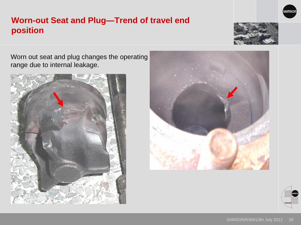
Worn-out Seat and Plug—Trend of travel end
position
Worn out seat and plug changes the operating
range due to internal leakage.

Damage due to erosion (Abrasive media)
SAMSON/KNN/13th July 2012 · 27

Control Valves & FF Smart Positioners
Typical valve failures
Eroded seat and plug → internal leakage
Erosion of valve body → finally external leakage
Leaking stuffing box → external leakage
Increased / decreased friction → higher / lower hysteresis
Closing (Zero) point shifting → deposits on sealing edge
Change in opening / closing breakaway torque (e.g. ball valves)
Poor control performance → External leakages in the pneumatic supply

Samson/KNN/13th July 2012 · 29
Partial Stroke Test
The Partial Stroke Test (PST) is particularly suitable for the status-oriented
detection of malfunctions in pneumatic shut-off valves. („check on a valve‘s ability to
move“). A valve which is normally in its end position can be prevented from seizing up
or getting jammed.
It is part of the standard positioner features.

Especially for on/off applications (critical ball or butterfly valves, maybe safety related)
Partial Stroke Test without disrupting plant operation (e.g.: 100% to 90% and backwards to the operation point)
Prevent the valve from becoming stuck
Starting time scheduled or manually
Step or ramp function (adjustable ramp to prevent overshoot)
Configurable test abortion conditions
Condensed/test status acc. to NE 107
Documentable & reliable
Goal: maximize the time between full proof tests -> Cost optimization
Full Stroke Test over the entire travel range is always required!
Partial Stroke Test
PRTPFD DU 2
1
months
PFD
12
SIL threshold
6 18 24
test intervall without PST
test tintervall with PST

Thanks for listening…
THANKS.
SAMSON/KNN/13th July 2012 27


