Controlling a Marionette with Human Motion Capture Data Katsu Yamane, Jessica K. Hodgins, and H. Benjamin Brown The Robotics Institute, Carnegie Mellon University E-mail: kyamane jkh hbb @cs.cmu.edu Abstract In this paper, we present a method for controlling a mo- torized, string-driven marionette using motion capture data from human actors. The motion data must be adapted for the marionette because its kinematic and dynamic proper- ties differ from those of the human actor in degrees of free- dom, limb length, workspace, mass distribution, sensors, and actuators. This adaptation is accomplished via an in- verse kinematics algorithm that takes into account marker positions, joint motion ranges, string constraints, and po- tential energy. We also apply a feedforward controller to prevent extraneous swings of the hands. Experimental re- sults show that our approach enables the marionette to per- form motions that are qualitatively similar to the original human motion capture data. 1 Introduction Entertainment is one of the more immediately prac- tical applications of humanoid robots and several robots have recently been developed for this purpose [1, 2, 3]. In this paper, we explore the use of an inexpensive entertain- ment robot controlled by motion capture data with the goal of making such robots readily available and easily pro- grammable. The robot is a marionette where the length and pivot points of the strings are controlled by eight servo motors that bring the hands and the feet of the marionette to the desired positions (Figure 1). Standard marionettes are puppets with strings operated by a human performer’s hands and fingers. Creating ap- pealing motion with such a puppet is difficult and requires extensive practice. Although for our marionette the servo motors move the strings, programming a robotic version of such a device by hand to produce expressive gestures would also be difficult. We solve this problem by using full-body human motion data to drive the motion. The hu- man motion data is recorded as the positions of markers in three dimensions while an actor tells a story with his or her hands. After adaptation, the data are used to drive the motion of the marionette by taking into account the mar- Figure 1: The motor-driven marionette and its model. The marionette is about 60cm tall. The shoulder and elbow joints have cloth stops to prevent unrealistic joint angles. ionette’s swing dynamics. These adaptations and dynam- ics compensation are necessary because the marionette has many fewer degrees of freedom and much smaller size than the human actor, strings rather than actuators at the joints, and no sensors except for the rotation of the motors. The method described in this paper consists of four steps: (1) identify the swing dynamics of the hands and design a feedforward controller to prevent swinging and obtain a desired response, (2) obtain the translation, ori- entation, and scaling parameters that map the measured marker positions for the human motion into the mari- onette’s workspace, (3) apply the controller to modify the mapped marker positions to prevent swing, and (4) com- pute the motor commands to bring the (virtual) markers at- tached to the marionette to the revised positions computed in step (3). The relationship between the four steps is illustrated in Figure 2. In steps (2) and (4), we solve the inverse kine- matics problem with many different constraints including marker positions, joint motion ranges, strings, and gravity. This algorithm is an extension of the first author’s previ- ous work [4]. In step (1), we model the dynamics of swing by capturing the response to a step input of each desired marker position and then use that response to design a feed- forward controller to compensate for the swing motion. As a demonstration of the algorithm, we include exper-
Transcript
Controlling a Marionette with Human Motion Capture Data
Katsu Yamane, Jessica K. Hodgins, and H. Benjamin BrownThe Robotics Institute, Carnegie Mellon University
In this paper, we present a method for controlling a mo-torized, string-driven marionette using motion capture datafrom human actors. The motion data must be adapted forthe marionette because its kinematic and dynamic proper-ties differ from those of the human actor in degrees of free-dom, limb length, workspace, mass distribution, sensors,and actuators. This adaptation is accomplished via an in-verse kinematics algorithm that takes into account markerpositions, joint motion ranges, string constraints, and po-tential energy. We also apply a feedforward controller toprevent extraneous swings of the hands. Experimental re-sults show that our approach enables the marionette to per-form motions that are qualitatively similar to the originalhuman motion capture data.
1 Introduction
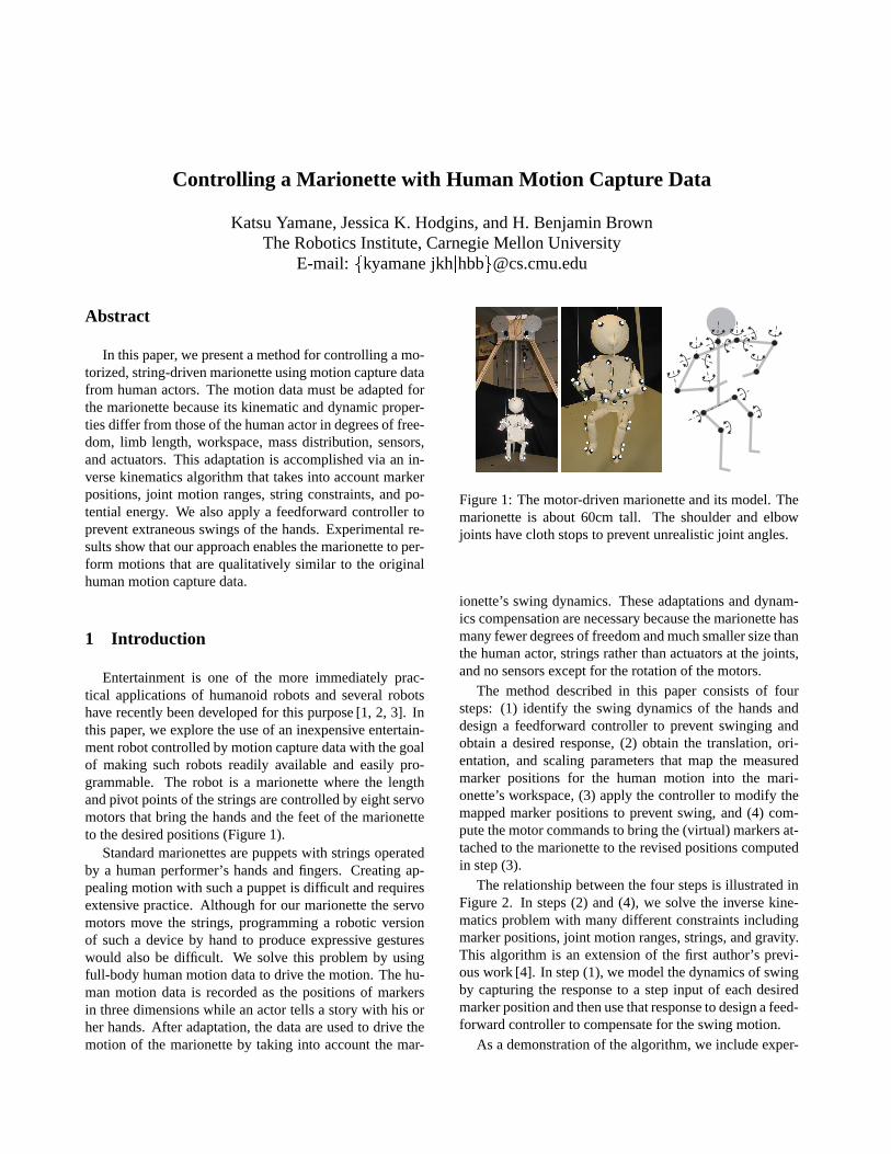
Entertainment is one of the more immediately prac-tical applications of humanoid robots and several robotshave recently been developed for this purpose [1, 2, 3]. Inthis paper, we explore the use of an inexpensive entertain-ment robot controlled by motion capture data with the goalof making such robots readily available and easily pro-grammable. The robot is a marionette where the lengthand pivot points of the strings are controlled by eight servomotors that bring the hands and the feet of the marionetteto the desired positions (Figure 1).
Standard marionettes are puppets with strings operatedby a human performer’s hands and fingers. Creating ap-pealing motion with such a puppet is difficult and requiresextensive practice. Although for our marionette the servomotors move the strings, programming a robotic versionof such a device by hand to produce expressive gestureswould also be difficult. We solve this problem by usingfull-body human motion data to drive the motion. The hu-man motion data is recorded as the positions of markersin three dimensions while an actor tells a story with his orher hands. After adaptation, the data are used to drive themotion of the marionette by taking into account the mar-
Figure 1: The motor-driven marionette and its model. Themarionette is about 60cm tall. The shoulder and elbowjoints have cloth stops to prevent unrealistic joint angles.
ionette’s swing dynamics. These adaptations and dynam-ics compensation are necessary because the marionette hasmany fewer degrees of freedom and much smaller size thanthe human actor, strings rather than actuators at the joints,and no sensors except for the rotation of the motors.
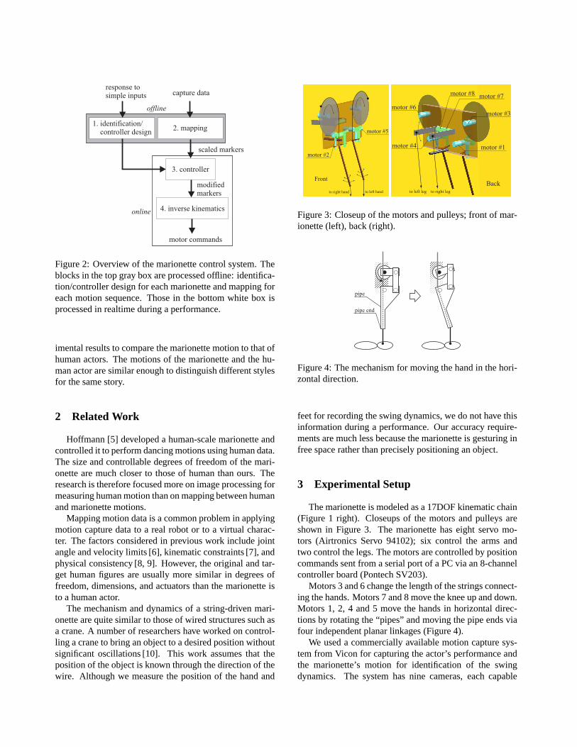
The method described in this paper consists of foursteps: (1) identify the swing dynamics of the hands anddesign a feedforward controller to prevent swinging andobtain a desired response, (2) obtain the translation, ori-entation, and scaling parameters that map the measuredmarker positions for the human motion into the mari-onette’s workspace, (3) apply the controller to modify themapped marker positions to prevent swing, and (4) com-pute the motor commands to bring the (virtual) markers at-tached to the marionette to the revised positions computedin step (3).
The relationship between the four steps is illustrated inFigure 2. In steps (2) and (4), we solve the inverse kine-matics problem with many different constraints includingmarker positions, joint motion ranges, strings, and gravity.This algorithm is an extension of the first author’s previ-ous work [4]. In step (1), we model the dynamics of swingby capturing the response to a step input of each desiredmarker position and then use that response to design a feed-forward controller to compensate for the swing motion.
As a demonstration of the algorithm, we include exper-
Figure 2: Overview of the marionette control system. Theblocks in the top gray box are processed offline: identifica-tion/controller design for each marionette and mapping foreach motion sequence. Those in the bottom white box isprocessed in realtime during a performance.
imental results to compare the marionette motion to that ofhuman actors. The motions of the marionette and the hu-man actor are similar enough to distinguish different stylesfor the same story.
2 Related Work
Hoffmann [5] developed a human-scale marionette andcontrolled it to perform dancing motions using human data.The size and controllable degrees of freedom of the mari-onette are much closer to those of human than ours. Theresearch is therefore focused more on image processing formeasuring human motion than on mapping between humanand marionette motions.
Mapping motion data is a common problem in applyingmotion capture data to a real robot or to a virtual charac-ter. The factors considered in previous work include jointangle and velocity limits [6], kinematic constraints [7], andphysical consistency [8, 9]. However, the original and tar-get human figures are usually more similar in degrees offreedom, dimensions, and actuators than the marionette isto a human actor.
The mechanism and dynamics of a string-driven mari-onette are quite similar to those of wired structures such asa crane. A number of researchers have worked on control-ling a crane to bring an object to a desired position withoutsignificant oscillations [10]. This work assumes that theposition of the object is known through the direction of thewire. Although we measure the position of the hand and
Front
motor #2
motor #5
to right hand to left hand
motor #8
motor #1
motor #3
motor #4
motor #6motor #7
to right legto left legBack
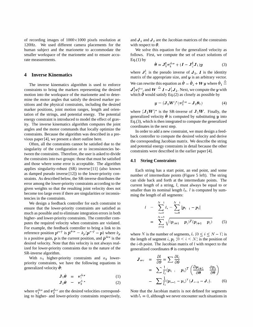
Figure 3: Closeup of the motors and pulleys; front of mar-ionette (left), back (right).
pipe
pipe end
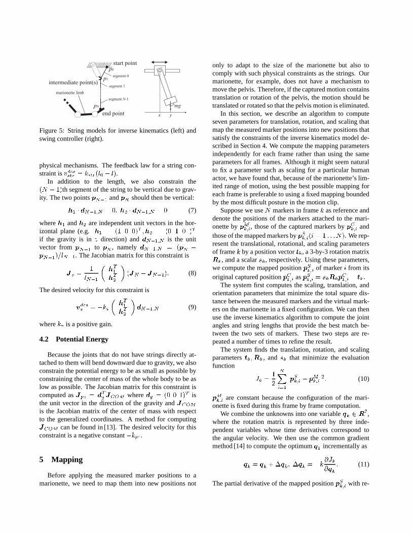
Figure 4: The mechanism for moving the hand in the hori-zontal direction.
feet for recording the swing dynamics, we do not have thisinformation during a performance. Our accuracy require-ments are much less because the marionette is gesturing infree space rather than precisely positioning an object.
3 Experimental Setup
The marionette is modeled as a 17DOF kinematic chain(Figure 1 right). Closeups of the motors and pulleys areshown in Figure 3. The marionette has eight servo mo-tors (Airtronics Servo 94102); six control the arms andtwo control the legs. The motors are controlled by positioncommands sent from a serial port of a PC via an 8-channelcontroller board (Pontech SV203).
Motors 3 and 6 change the length of the strings connect-ing the hands. Motors 7 and 8 move the knee up and down.Motors 1, 2, 4 and 5 move the hands in horizontal direc-tions by rotating the “pipes” and moving the pipe ends viafour independent planar linkages (Figure 4).
We used a commercially available motion capture sys-tem from Vicon for capturing the actor’s performance andthe marionette’s motion for identification of the swingdynamics. The system has nine cameras, each capable
of recording images of 1000�1000 pixels resolution at120Hz. We used different camera placements for thehuman subject and the marionette to accommodate thesmaller workspace of the marionette and to ensure accu-rate measurements.
4 Inverse Kinematics
The inverse kinematics algorithm is used to enforceconstraints to bring the markers representing the desiredmotion into the workspace of the marionette and to deter-mine the motor angles that satisfy the desired marker po-sitions and the physical constraints, including the desiredmarker positions, joint motion ranges, length and orien-tation of the strings, and potential energy. The potentialenergy constraint is introduced to model the effect of grav-ity. The inverse kinematics algorithm computes the jointangles and the motor commands that locally optimize theconstraints. Because the algorithm was described in a pre-vious paper [4], we present a short outline here.
Often, all the constraints cannot be satisfied due to thesingularity of the configuration or to inconsistencies be-tween the constraints. Therefore, the user is asked to dividethe constraints into two groups: those that must be satisfiedand those where some error is acceptable. The algorithmapplies singularity-robust (SR) inverse [11] (also knownas damped pseudo inverse [12]) to the lower-priority con-straints. As described below, the SR-inverse distributes theerror among the lower-priority constraints according to thegiven weights so that the resulting joint velocity does notbecome too large even if there are singularities or inconsis-tencies in the constraints.
We design a feedback controller for each constraint toensure that the lower-priority constraints are satisfied asmuch as possible and to eliminate integration errors in bothhigher- and lower-priority constraints. The controller com-putes the required velocity when constraints are violated.For example, the feedback controller to bring a link to itsreference positionpref is �pdes � kp�p
ref � p� wherekpis a positive gain,p is the current position, and�pdes is thedesired velocity. Note that this velocity is not always real-ized for lower-priority constraints due to the nature of theSR-inverse algorithm.
With n� higher-priority constraints andn� lower-priority constraints, we have the following equations ingeneralized velocity��:
J� �� � vdes� (1)
J� �� � vdes� (2)
wherevdes� andvdes� are the desired velocities correspond-ing to higher- and lower-priority constraints respectively,
andJ� andJ� are the Jacobian matrices of the constraintswith respect to�.
We solve this equation for the generalized velocity asfollows. First, we compute the set of exact solutions ofEq.(1) by
�� � J��v
des� � �I � J
��J��y (3)
whereJ �� is the pseudo inverse ofJ�, I is the identity
matrix of the appropriate size, andy is an arbitrary vector.
We can rewrite this equation as�� � ����Wy where �����
J��v
des� , andW
�� I�J��J�. Next, we compute they with
which �� would satisfy Eq.(2) as closely as possible by
y � �J�W ���vdes� � J���� (4)
where�J�W �� is the SR-inverse ofJ�W . Finally, thegeneralized velocity�� is computed by substitutingy intoEq.(3), which is then integrated to compute the generalizedcoordinates in the next step.
In order to add a new constraint, we must design a feed-back controller to compute the desired velocity and derivethe corresponding Jacobian matrix. We describe the stringand potential energy constraints in detail because the otherconstraints were described in the earlier paper [4].
4.1 String Constraints
Each string has a start point, an end point, and somenumber of intermediate points (Figure 5 left). The stringcan slide back and forth at the intermediate points. Thecurrent length of a string,l, must always be equal to orsmaller than its nominal lengthl�. l is computed by sum-ming the length of all segments:
l �
N��Xi��
li �
N��Xi��
jpi�� � pij
�N��Xi��
q�pi�� � pi�
T �pi�� � pi� (5)
whereN is the number of segments,li �� � i � N � �� isthe length of segmenti, pi �� � i � N� is the position ofthei-th point. The Jacobian matrix ofl with respect to thegeneralized coordinates� is computed by
Jstr ��l
���X �li
��
�X �
li�pi�� � pi�
T
��pi����
��pi��
�
�X �
li�pi�� � pi�
T �J i�� � J i�� (6)
Note that the Jacobian matrix is not defined for segmentswith li � �, although we never encounter such situations in
physical mechanisms. The feedback law for a string con-straint isvdesstr � kstr�l� � l�.
In addition to the length, we also constrain the�N � ��th segment of the string to be vertical due to grav-ity. The two pointspN�� andpN should then be vertical:
h� � dN���N � �� h� � dN���N � � (7)
whereh� andh� are independent unit vectors in the hor-izontal plane (e.g.h� � �� � ��T �h� � �� � � �T
if the gravity is in z direction) anddN���N is the unitvector from pN�� to pN , namelydN���N � �pN �pN����lN��. The Jacobian matrix for this constraint is
Jv ��
lN��
�hT�hT�
��JN � JN���� (8)
The desired velocity for this constraint is
vdesv � �kv
�hT�hT�
�dN���N (9)
wherekv is a positive gain.
4.2 Potential Energy
Because the joints that do not have strings directly at-tached to them will bend downward due to gravity, we alsoconstrain the potential energy to be as small as possible byconstraining the center of mass of the whole body to be aslow as possible. The Jacobian matrix for this constraint iscomputed asJpe � dTg JCOM wheredg � �� � ��T isthe unit vector in the direction of the gravity andJCOM
is the Jacobian matrix of the center of mass with respectto the generalized coordinates. A method for computingJCOM can be found in [13]. The desired velocity for thisconstraint is a negative constant�kpe.
5 Mapping
Before applying the measured marker positions to amarionette, we need to map them into new positions not
only to adapt to the size of the marionette but also tocomply with such physical constraints as the strings. Ourmarionette, for example, does not have a mechanism tomove the pelvis. Therefore, if the captured motion containstranslation or rotation of the pelvis, the motion should betranslated or rotated so that the pelvis motion is eliminated.
In this section, we describe an algorithm to computeseven parameters for translation, rotation, and scaling thatmap the measured marker positions into new positions thatsatisfy the constraints of the inverse kinematics model de-scribed in Section 4. We compute the mapping parametersindependently for each frame rather than using the sameparameters for all frames. Although it might seem naturalto fix a parameter such as scaling for a particular humanactor, we have found that, because of the marionette’s lim-ited range of motion, using the best possible mapping foreach frame is preferable to using a fixed mapping boundedby the most difficult posture in the motion clip.
Suppose we useN markers in framek as reference anddenote the positions of the markers attached to the mari-onette bypMk�i, those of the captured markers bypCk�i andthose of the mapped markers bypSk�i�i � � � � �N�. We rep-resent the translational, rotational, and scaling parametersof framek by a position vectortk, a 3-by-3 rotation matrixRk, and a scalarsk, respectively. Using these parameters,we compute the mapped positionpSk�i of markeri from itsoriginal captured positionpCk�i aspSk�i � skRkp
Ck�i � tk�
The system first computes the scaling, translation, andorientation parameters that minimize the total square dis-tance between the measured markers and the virtual mark-ers on the marionette in a fixed configuration. We can thenuse the inverse kinematics algorithm to compute the jointangles and string lengths that provide the best match be-tween the two sets of markers. These two steps are re-peated a number of times to refine the result.
The system finds the translation, rotation, and scalingparameterstk�Rk� and sk that minimize the evaluationfunction
Jk ��
�
NXi��
jpSk�i � pMk�ij�� (10)
pMk�i are constant because the configuration of the mari-onette is fixed during this frame by frame computation.
We combine the unknowns into one variableqk � R�,where the rotation matrix is represented by three inde-pendent variables whose time derivatives correspond tothe angular velocity. We then use the common gradientmethod [14] to compute the optimumqk incrementally as
qk � qk ��qk� �qk � �k�Jk�qk
� (11)
The partial derivative of the mapped positionpSk�i with re-
spect toqk is computed as
Hi�k��
�pSk�i�qk
��I� r� Rkp
Ck�i
�(12)
whereI� is the 3-by-3 identity matrix,r�� skRkp
Ck�i, and
r� is the cross product matrix ofr. UsingHk�i, thepartial derivative ofJk is computed by
�Jk�qk
� �pSk�i � pMk�i�THk�i� (13)
We apply this process to each frame independently bystarting from the same initial guess. Using the result ofprevious frame as the initial guess would reduce the com-putation time, but the algorithm might not recover from afailure to obtain good mapping parameters in one framedue to, for example, missing markers. Regardless of theinitial guess, the resulting mapping parameters may not becontinuous because the algorithm is finding only a localminima. Small discontinuities are not a problem, however,because the marker positions are “filtered” by the feedbackcontroller and by the SR-inverse used in the inverse kine-matics computation.
6 Controlling Swing
If the mapped motion is applied directly to the mari-onette, the hands of the marionette will swing and the mo-tion will not be a good match to that of the human actor.We solve this problem by building a simple linear modelfor the swing dynamics and experimentally identifying itsparameters. An alternative approach would be to model thefull dynamics of the marionette, but this tactic is not prac-tical because of uncertainty in the model parameters andthe limitations of the motors and sensors. Because mari-onette is made of wood and cloth, it is difficult to preciselydetermine the mass, inertia, and friction parameters of thejoints. The joints are cleverly designed to prevent unre-alistic joint angles (Figure 1), but this design also makesmodeling of the system more difficult. The motors are in-expensive hobby servos and do not provide precise control.Furthermore, we do not have sensors that measure the cur-rent state of the marionette during a performance.
For the simple model of the dynamics, we make threeassumptions. (1) Swinging of the hands occurs in the hor-izontal plane. Pulling the hands or legs up or down doesnot create a swinging motion. (2) The motion of a handalong thex axis (left/right) and they axis (forward/back)are independently controlled by one motor each. (3) Thereis no coupling between the swinging of the left and righthands. These simplifying assumptions allow us to modelswing as four independent systems, two for each hand.
Some situations occur in which the second and third as-sumptions do not hold. The hand marker sometimes movesalong a circular trajectory rather than a straight line. Themarkers with fixed inputs inevitably move slightly whenother markers are moved, violating the last assumption.Both problems are most likely to occur when the hand isrelatively close to the body because the stiffness of theelbow and shoulder joints forces the hand away from thebody.
6.1 Modeling of Swing Dynamics
In this section we describe the swing dynamics modelthat, when combined with the feedback controller of the in-verse kinematics algorithm in Section 4, predicts the swingmotion.
The inverse kinematics algorithm included a propor-tional controller, where the velocity of the pipe end�x iscomputed from the current position of the pipe endx andthe desired positionu as �x � k�u � x� wherek is a con-stant gain. Therefore the transfer function from the markertrajectory to the motion of the pipe end takes the form
x ��
aiks� �u (14)
whereu is the input (marker trajectory),x is the output(motion of the pipe end),s is the Laplace transforma-tion operator, andaik is the parameter that determines theamount of delay.
The motion of the hand for a given trajectory of the pipeend can be modeled as a pendulum with a moving base(Figure 5 right). Using the length of the penduluml and thedamping termd, the equation of motion of the pendulumunder gravityg is linearized aroundx � y as�y � l�g�x�y� � d� �x � �y�� In general, therefore, the transfer functionfrom the motion of the pipe end to the marker motion iswritten as
y �bss� �
ass� � bss� �x (15)
wherey is the output (actual marker trajectory) andasandbs are the parameters that determine the frequency anddamping respectively.
Combining Eqs.(14) and (15), the system computing thedesired marker trajectory from the actual trajectory will bea 3rd-order system. We estimate the three parameters frommotion capture data.
The gains of both systems were assumed to be 1, whichturned out to be not true, probably because the joint motionranges of the pipe prevented the pipe end from reaching thedesired position or because the stiffness of the arm jointsdid not allow the string to be perpendicular. We decided notto consider these model errors because the desired marker
position is not achievable if it violates the joint range con-straint and the stiffness strongly depends on the configura-tion of the arm making the system too complicated.
6.2 Feedforward Controller
The feedforward controllerK is formed by connectingthe desired responseGD and the inverse of the estimatedmodelPm in series, that is,K � GDP
��m � In order for
the controller to be proper (the order of the denominator ofthe transfer function is larger than that of the numerator),the order ofGD must be larger than 2. We selected a 3rd-orderGD so that the output of the controller is continuous.We can also improve the response of the total system byselectingGD with a smaller delay. In practice, however,we cannot use an arbitrarily fastGD because as the gain ofthe controller increases, it becomes sensitive to modelingerrors.
The parameters of the string dynamics model,as andbs,depend on the length of the strings; therefore, we repeat theidentification process for several different heights for eachhand and design a controller for each model. We then applythe weighted sum of the outputs of the three controllers,where the weights are determined according to the actualheight during a performance.
7 Results
The inverse kinematics computation to obtain the motorcommands was repeated four times for each frame to en-sure convergence. The total computation time was about36ms per frame on a laptop PC with a Mobile PentiumIII1GHz processor. Motor commands were sent every 50ms.
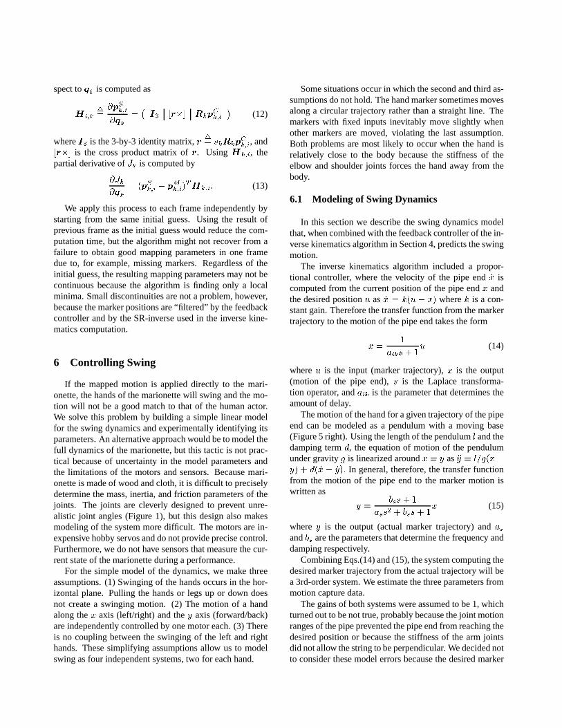
Based on the inverse kinematics computation, we de-veloped an online control interface for the marionette. Themodel consists of nine string length constraints, joint mo-tion range constraints for eight joints, two string directionconstraints, and the potential energy constraint. The usercan select a marker and drag it to any position. The inversekinematics algorithm then computes the motor commandsand the joint angles to move the marker to the specified po-sition. Figure 6 shows several snapshots of the marionettemodel and the corresponding postures of the actual mari-onette.
The swing controller was designed for three differentheights (���� m, �����m, and���� m, measured fromthe center of the panel where the motors and pulleys areattached). We had a total of twelve controllers for thexandy directions of both hands. Table 1 lists the parametersets for the right hand in thex direction. The parameterswere tuned manually, although it should also be possible toapply standard system identification techniques [15].
Figure 6: Postures generated by the interactive interface.Above: marionette, below: simulation.
Table 1: Parameters of the string dynamics models for thex direction of the right hand.
height [m] -0.59 -0.44 -0.29
aik 0.8as 0.063 0.061 0.059bs 0.07 0.06 0.02
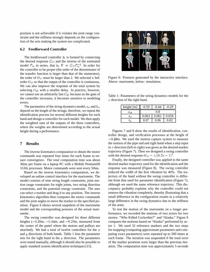
Figures 7 and 8 show the results of identification, con-troller design, and verification processes at the height of���� m. We used the motion capture system to measurethe motion of the pipe end and right hand when a step inputin x direction (left to right) was given as the desired markertrajectory (Figure 7). Then we designed a swing controllerwith the desired responseGD � ������s� ����
Finally, the designed controller was applied to the samedesired marker trajectory used for the identification and theresponse was measured (Figure 8). The swing controllerreduced the width of the first vibration by 40%. The tra-jectory of the hand without the swing controller is differ-ent from that used for parameter identification (Figure 7),although we used the same reference trajectory. This dis-crepancy probably explains why the controller could notremove the vibration completely, thereby illustrating that asmall difference in the configuration results in a relativelylarge difference in the swing dynamics due to the stiffnessof the arms.
To test the motion of the marionette on a longer per-formance, we recorded the motions of two actors for twostories: “Who Killed Cockrobin?” and “Alaska.” Figure 9compares the motions based on “Alaska” performed by ac-tor 1. We used 32 reference markers and the two stepsfor mapping (computing approximate parameters and com-puting exact parameters) were repeated up to 500 times ateach frame. The iteration was suspended if the total errorof the marker positions were larger than the previous iter-ation. The computation time was approximately 5 seconds
Am
plitu
de
0 1 2 3 4 5 6 7 8 9 10-0.5
0
0.5
1
1.5A
mpl
itude
0 1 2 3 4 5 6 7 8 9 10-0.5
0
0.5
1
1.5
Pipe end
HandTime [s]
Time [s]
actual response
model response
input
actual response
model response
Figure 7: Actual and model responses to a step input. Theamplitude of each motion is normalized. The hand of themarionette comes close to its head at this height.
0 1 2 3 4 5 6 7 8 9 10-0.2
0
0.2
0.4
0.6
0.8
1
1.2
disp
lace
men
t
time [s]
hand (with swing controller)
hand (without swing controller)
pipe (with swing controller)
pipe (without swing controller)
Figure 8: Response of the pipe and the hand to a step input.
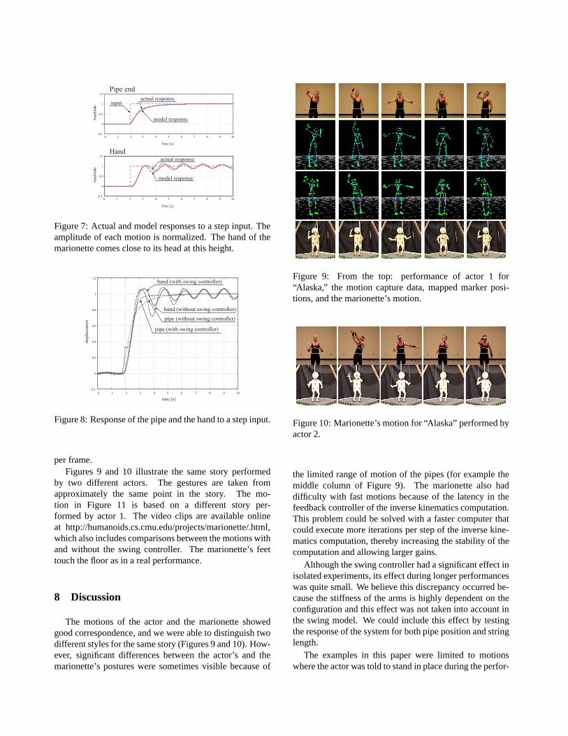
per frame.Figures 9 and 10 illustrate the same story performed
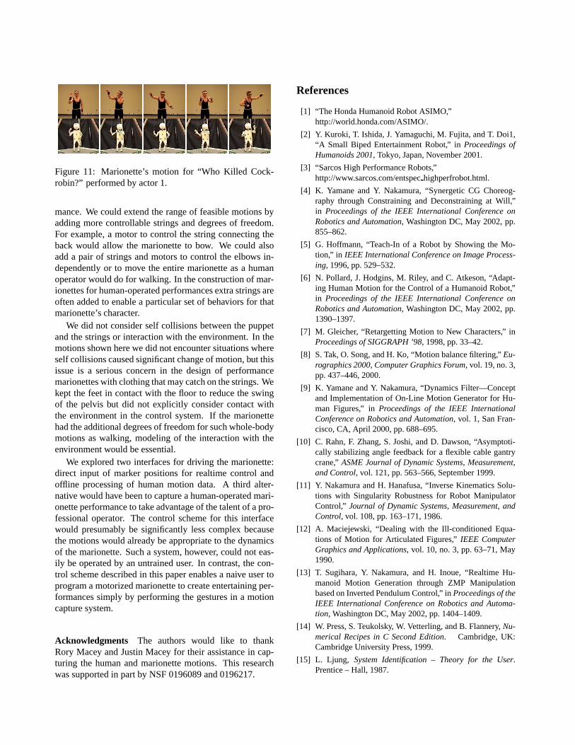
by two different actors. The gestures are taken fromapproximately the same point in the story. The mo-tion in Figure 11 is based on a different story per-formed by actor 1. The video clips are available onlineat http://humanoids.cs.cmu.edu/projects/marionette/.html,which also includes comparisons between the motions withand without the swing controller. The marionette’s feettouch the floor as in a real performance.
8 Discussion
The motions of the actor and the marionette showedgood correspondence, and we were able to distinguish twodifferent styles for the same story (Figures 9 and 10). How-ever, significant differences between the actor’s and themarionette’s postures were sometimes visible because of
Figure 9: From the top: performance of actor 1 for“Alaska,” the motion capture data, mapped marker posi-tions, and the marionette’s motion.
Figure 10: Marionette’s motion for “Alaska” performed byactor 2.
the limited range of motion of the pipes (for example themiddle column of Figure 9). The marionette also haddifficulty with fast motions because of the latency in thefeedback controller of the inverse kinematics computation.This problem could be solved with a faster computer thatcould execute more iterations per step of the inverse kine-matics computation, thereby increasing the stability of thecomputation and allowing larger gains.
Although the swing controller had a significant effect inisolated experiments, its effect during longer performanceswas quite small. We believe this discrepancy occurred be-cause the stiffness of the arms is highly dependent on theconfiguration and this effect was not taken into account inthe swing model. We could include this effect by testingthe response of the system for both pipe position and stringlength.
The examples in this paper were limited to motionswhere the actor was told to stand in place during the perfor-
Figure 11: Marionette’s motion for “Who Killed Cock-robin?” performed by actor 1.
mance. We could extend the range of feasible motions byadding more controllable strings and degrees of freedom.For example, a motor to control the string connecting theback would allow the marionette to bow. We could alsoadd a pair of strings and motors to control the elbows in-dependently or to move the entire marionette as a humanoperator would do for walking. In the construction of mar-ionettes for human-operated performances extra strings areoften added to enable a particular set of behaviors for thatmarionette’s character.
We did not consider self collisions between the puppetand the strings or interaction with the environment. In themotions shown here we did not encounter situations whereself collisions caused significant change of motion, but thisissue is a serious concern in the design of performancemarionettes with clothing that may catch on the strings. Wekept the feet in contact with the floor to reduce the swingof the pelvis but did not explicitly consider contact withthe environment in the control system. If the marionettehad the additional degrees of freedom for such whole-bodymotions as walking, modeling of the interaction with theenvironment would be essential.
We explored two interfaces for driving the marionette:direct input of marker positions for realtime control andoffline processing of human motion data. A third alter-native would have been to capture a human-operated mari-onette performance to take advantage of the talent of a pro-fessional operator. The control scheme for this interfacewould presumably be significantly less complex becausethe motions would already be appropriate to the dynamicsof the marionette. Such a system, however, could not eas-ily be operated by an untrained user. In contrast, the con-trol scheme described in this paper enables a naive user toprogram a motorized marionette to create entertaining per-formances simply by performing the gestures in a motioncapture system.
Acknowledgments The authors would like to thankRory Macey and Justin Macey for their assistance in cap-turing the human and marionette motions. This researchwas supported in part by NSF 0196089 and 0196217.
References
[1] “The Honda Humanoid Robot ASIMO,”http://world.honda.com/ASIMO/.
[2] Y. Kuroki, T. Ishida, J. Yamaguchi, M. Fujita, and T. Doi1,“A Small Biped Entertainment Robot,” inProceedings ofHumanoids 2001, Tokyo, Japan, November 2001.
[3] “Sarcos High Performance Robots,”http://www.sarcos.com/entspechighperfrobot.html.
[4] K. Yamane and Y. Nakamura, “Synergetic CG Choreog-raphy through Constraining and Deconstraining at Will,”in Proceedings of the IEEE International Conference onRobotics and Automation, Washington DC, May 2002, pp.855–862.
[5] G. Hoffmann, “Teach-In of a Robot by Showing the Mo-tion,” in IEEE International Conference on Image Process-ing, 1996, pp. 529–532.
[6] N. Pollard, J. Hodgins, M. Riley, and C. Atkeson, “Adapt-ing Human Motion for the Control of a Humanoid Robot,”in Proceedings of the IEEE International Conference onRobotics and Automation, Washington DC, May 2002, pp.1390–1397.
[7] M. Gleicher, “Retargetting Motion to New Characters,” inProceedings of SIGGRAPH ’98, 1998, pp. 33–42.
[8] S. Tak, O. Song, and H. Ko, “Motion balance filtering,”Eu-rographics 2000, Computer Graphics Forum, vol. 19, no. 3,pp. 437–446, 2000.
[9] K. Yamane and Y. Nakamura, “Dynamics Filter—Conceptand Implementation of On-Line Motion Generator for Hu-man Figures,” inProceedings of the IEEE InternationalConference on Robotics and Automation, vol. 1, San Fran-cisco, CA, April 2000, pp. 688–695.
[10] C. Rahn, F. Zhang, S. Joshi, and D. Dawson, “Asymptoti-cally stabilizing angle feedback for a flexible cable gantrycrane,”ASME Journal of Dynamic Systems, Measurement,and Control, vol. 121, pp. 563–566, September 1999.
[11] Y. Nakamura and H. Hanafusa, “Inverse Kinematics Solu-tions with Singularity Robustness for Robot ManipulatorControl,” Journal of Dynamic Systems, Measurement, andControl, vol. 108, pp. 163–171, 1986.
[12] A. Maciejewski, “Dealing with the Ill-conditioned Equa-tions of Motion for Articulated Figures,”IEEE ComputerGraphics and Applications, vol. 10, no. 3, pp. 63–71, May1990.
[13] T. Sugihara, Y. Nakamura, and H. Inoue, “Realtime Hu-manoid Motion Generation through ZMP Manipulationbased on Inverted Pendulum Control,” inProceedings of theIEEE International Conference on Robotics and Automa-tion, Washington DC, May 2002, pp. 1404–1409.
[14] W. Press, S. Teukolsky, W. Vetterling, and B. Flannery,Nu-merical Recipes in C Second Edition. Cambridge, UK:Cambridge University Press, 1999.
[15] L. Ljung, System Identification – Theory for the User.Prentice – Hall, 1987.