96
Conventional Machining - 2 ME 338: Manufacturing Processes II Instructor: Ramesh Singh; Notes: Profs. Singh/Melkote/Colton

Conventional Machining - 2
ME 338: Manufacturing Processes II
Instructor: Ramesh Singh; Notes: Profs.
Singh/Melkote/Colton
Outline
• Machining basics
• Mechanics of chip formation
• Tool wear and tool life
ME 338: Manufacturing Processes II
Instructor: Ramesh Singh; Notes: Profs.
Singh/Melkote/Colton
• Surface finish and integrity

Machining Basics
• Conventional machining: removal of material
from a workpiece in the form of a chip via
brute force of a sharp cutting tool
chiptool chip
tool
ME 338: Manufacturing Processes II
Instructor: Ramesh Singh; Notes: Profs.
Singh/Melkote/Colton
chip tool
Orthogonal Cutting Oblique Cutting

Classification of Conventional Machining
• Cutting processes
– Single point: e.g. shaping, planing, turning, boring, etc.
– Multiple point: e.g. milling, drilling, etc.
• Abrasive processes
– Grinding, honing, etc.
ME 338: Manufacturing Processes II
Instructor: Ramesh Singh; Notes: Profs.
Singh/Melkote/Colton

Major Process Variables
• Independent variables– Cutting conditions e.g. feed, speed, depth of cut
– Tool and workpiece materials
– Tool geometry
– Machine tool
– Workholding devices
– Cutting fluids
ME 338: Manufacturing Processes II
Instructor: Ramesh Singh; Notes: Profs.
Singh/Melkote/Colton
– Cutting fluids
• Dependent variables– Chip type
– Cutting forces and energy dissipation
– Temperature rise
– Tool wear
– Surface finish/integrity

Major Chip Types
• Continuous: ductile metals, thermoplastics
• Continuous with built-up edge (BUE): at low
ME 338: Manufacturing Processes II
Instructor: Ramesh Singh; Notes: Profs.
Singh/Melkote/Colton
• Continuous with built-up edge (BUE): at low
cutting speeds

Major Chip Types
• Segmented: low thermal diffusivity materials,
very hard steels
• Discontinuous: brittle materials
ME 338: Manufacturing Processes II
Instructor: Ramesh Singh; Notes: Profs.
Singh/Melkote/Colton
• Discontinuous: brittle materials

Chip Types-Characteristics
• (a) Continuous chip with narrow primary shear zone– ductile materials at high speed– bad for automation (use chip breakers)
• (b) Secondary shear zone at chip-tool
ME 338: Manufacturing Processes II
Instructor: Ramesh Singh; Notes: Profs.
Singh/Melkote/Colton
• (b) Secondary shear zone at chip-tool interface– increased energy dissipation
• (c) Continuous chip with built up edge (BUE)– high plastic working– bad for automation

Chip Types
• (d) Continuous chip with large primary shear zone– soft metals at low speeds and low rake angles
– poor surface finish
– residual stresses
ME 338: Manufacturing Processes II
Instructor: Ramesh Singh; Notes: Profs.
Singh/Melkote/Colton
– residual stresses
• (e) Segmented chip– low thermal conductivity materials
• (f) Discontinuous chip– low ductility materials and/or negative rake angles
– good for automation

Chip Formation - AISI 4340
< 50 100-200
onset at 400
onset> 800
SFPM
50-100> 3200
ME 338: Manufacturing Processes II
Instructor: Ramesh Singh; Notes: Profs.
Singh/Melkote/Colton
SFPMDiscontinuous
Built-upedge
ContinuousChip
Shearlocalized
chip
Catastrophicshear
Completeseparation

Piispanen’s Card Model of Continuous Chip
Formation
chip
cutting toolshear plane
Tool-chip friction
ME 338: Manufacturing Processes II
Instructor: Ramesh Singh; Notes: Profs.
Singh/Melkote/Colton
workpiece
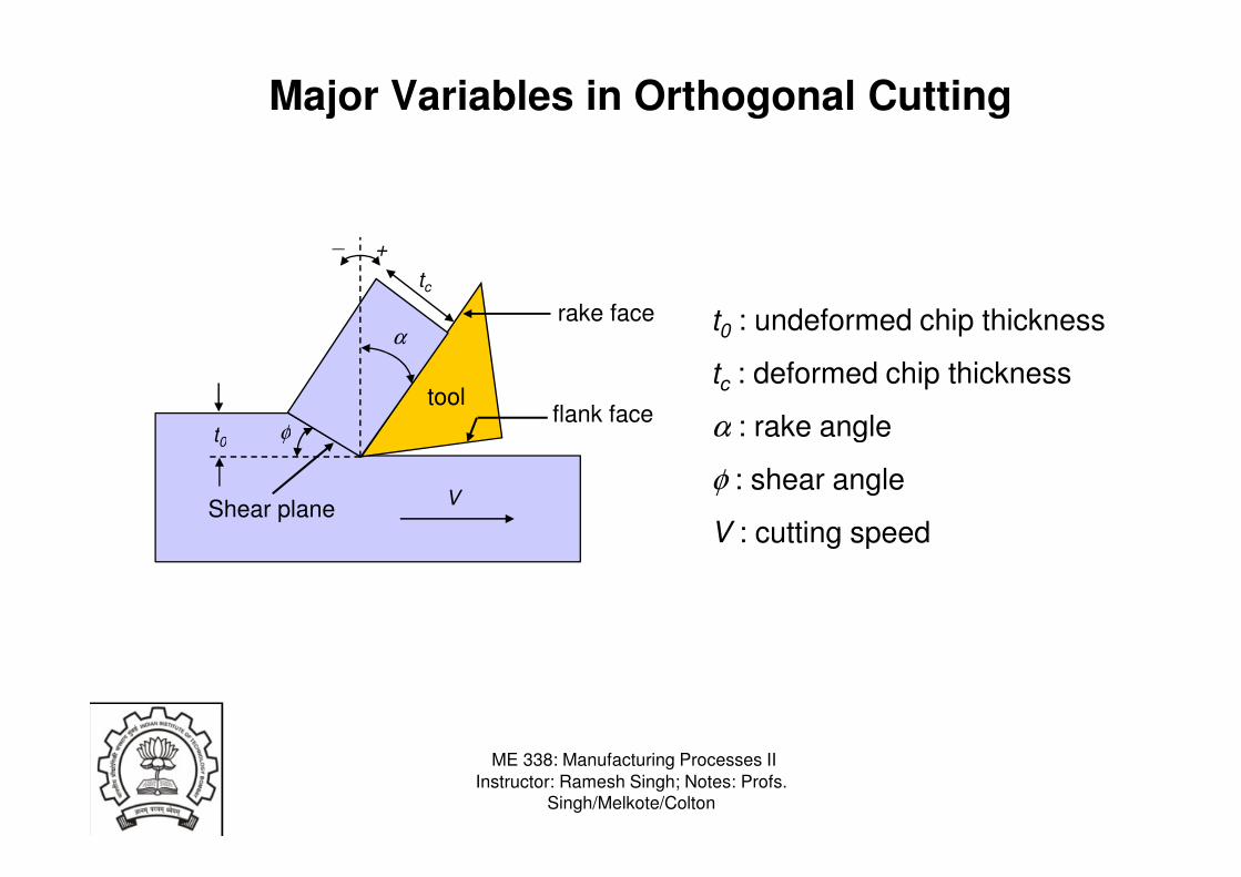
Major Variables in Orthogonal Cutting
rake face
t0
α
_ +
tc
φ
toolflank face
t0 : undeformed chip thickness
tc : deformed chip thickness
α : rake angle
ME 338: Manufacturing Processes II
Instructor: Ramesh Singh; Notes: Profs.
Singh/Melkote/Colton
t0 φ
VShear plane
α : rake angle
φ : shear angle
V : cutting speed
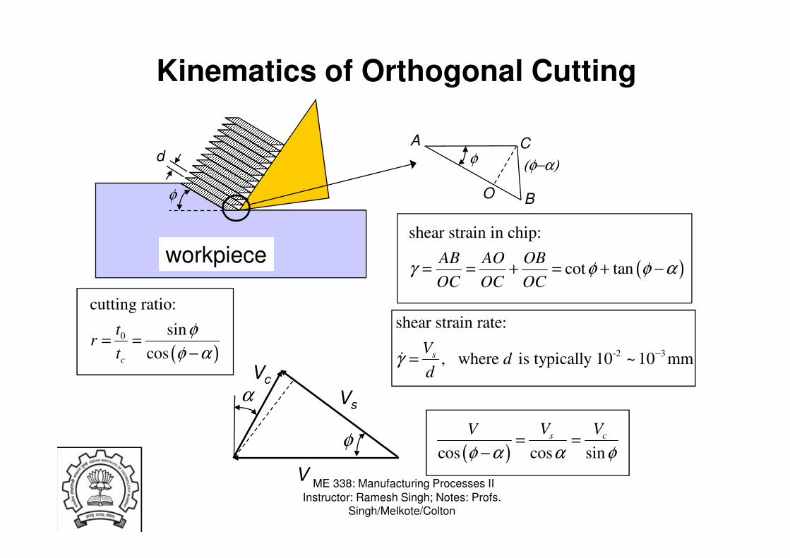
Kinematics of Orthogonal Cutting
workpiece
d
φ
φA C
BO
(φ−α)
( )
shear strain in chip:
cot tanAB AO OB
OC OC OCγ φ φ α= = + = + −
ME 338: Manufacturing Processes II
Instructor: Ramesh Singh; Notes: Profs.
Singh/Melkote/Colton
α
φ
Vs
V
Vc
( )0
cutting ratio:
sin
cosc
tr
t
φ
φ α= =
−
( )OC OC OC
( )cos cos sin
s cV VV
φ α α φ= =
−
-2 3
shear strain rate:
, where is typically 10 ~ 10 mmsV
dd
γ −=�

Kinematics of Orthogonal Cutting
Vs = shear velocity (along shear plane)
Vc = chip velocity
• Typical strains, γ = 2~5
ME 338: Manufacturing Processes II
Instructor: Ramesh Singh; Notes: Profs.
Singh/Melkote/Colton
4 6 -110 ~ 10 sγ =�• Typical strains, γ = 2~5
• Typical strain rates,
• Deformed chip thickness, tc > undeformed
chip thickness, t0 � r < 1

Forces in Orthogonal Cutting
Knowledge of cutting forces needed for:
– Estimation of power requirements
ME 338: Manufacturing Processes II
Instructor: Ramesh Singh; Notes: Profs.
Singh/Melkote/Colton
– Machine tool design e.g. static/dynamic stiffness
– Part accuracy e.g. tool-workpiece deflections

Forces in Orthogonal Cutting
Assumptions
– 2-d cutting process � plane strain process � 2-d
force system
– t0 << w (width of cut)
– Infinitely sharp cutting edge
ME 338: Manufacturing Processes II
Instructor: Ramesh Singh; Notes: Profs.
Singh/Melkote/Colton
– Infinitely sharp cutting edge
– Continuous chip with no BUE
– No chip curl
– No tool wear
– Uniform shear and normal stresses along shear plane and tool-chip interface
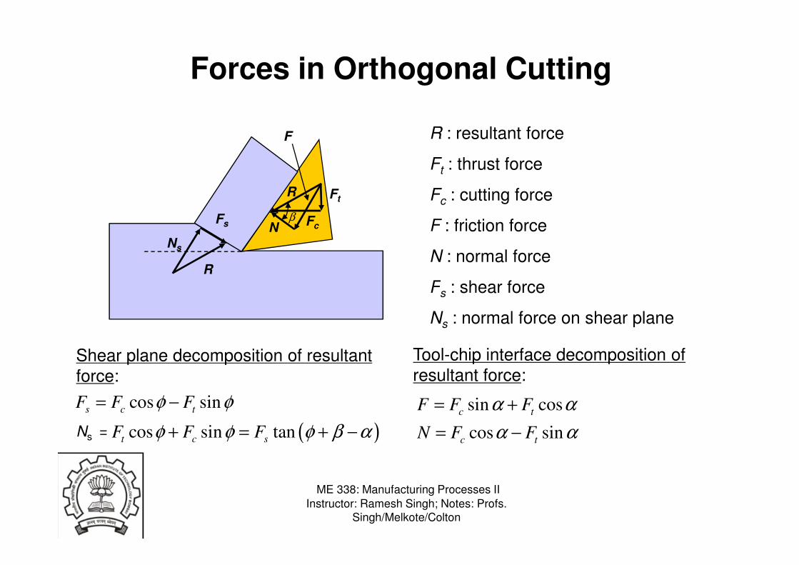
Forces in Orthogonal Cutting
R : resultant force
Ft : thrust force
Fc : cutting force
F : friction force
N : normal force
F : shear forceR
Fs
Ns
Ft
FcN
F
R
β
ME 338: Manufacturing Processes II
Instructor: Ramesh Singh; Notes: Profs.
Singh/Melkote/Colton
( )
cos sin
cos sin tan
s c t
n t c s
F F F
F F F F
φ φ
φ φ φ β α
= −
= + = + −
Fs : shear force
Ns : normal force on shear plane
Shear plane decomposition of resultant
force:
Tool-chip interface decomposition of
resultant force:
sin cos
cos sin
c t
c t
F F F
N F F
α α
α α
= +
= −Ns

Forces in Orthogonal Cutting
R
Fs
Ns
Ft
FcN
F
R
β
Tool-chip interface mean friction:
tantan
tan
t c
c t
F FF
N F F
αµ β
α
+= = =
−
Forces:
( )coss
F R φ β α= + −
ME 338: Manufacturing Processes II
Instructor: Ramesh Singh; Notes: Profs.
Singh/Melkote/Colton
( )
0
0
sin
sin cos sin
ss s
s
s
c tn
s
FF A
A
wtA
F FF
A wt
τ τ
φ
φ φ φσ
= → =
=
+= =
Shear plane stresses:
( )
( )
( )( )
( )( )
0
0
cos
cos
cos
sin cos
sin
sin cos
s
c
c
t
F R
F R
wtF
wtF
φ β α
β α
τ β α
φ φ β α
τ β α
φ φ β α
= + −
= −
−=
+ −
−=
+ −
0
0
c
t
F wt
F wt
∝
∝
Ns

Merchant’s Force Circle
Ns
F
Fs α
α
φ
β−α
VFc
ME 338: Manufacturing Processes II
Instructor: Ramesh Singh; Notes: Profs.
Singh/Melkote/Colton
Ft
βN
F
R
α
M. Eugene Merchant1913 - 2006

Cutting With an Oblique Tool
ME 338: Manufacturing Processes II
Instructor: Ramesh Singh; Notes: Profs.
Singh/Melkote/Colton
Figure 20.9 (a) Schematic illustration of cutting with an oblique
tool. (b) Top view showing the inclination angle, i. (c) Types of
chips produced with different inclination.
( )1 2 2sin sin cos sine ni iα α−= +
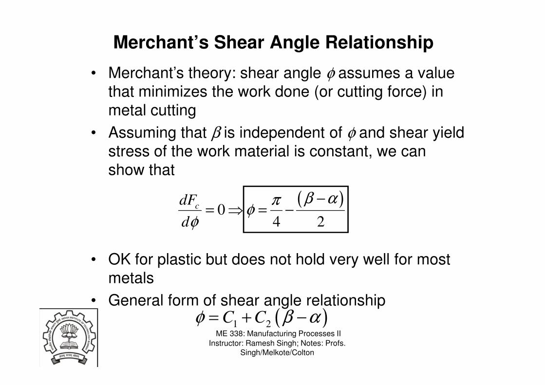
Merchant’s Shear Angle Relationship
• Merchant’s theory: shear angle φ assumes a value that minimizes the work done (or cutting force) in metal cutting
• Assuming that β is independent of φ and shear yield stress of the work material is constant, we can show that
( )dF β απ −
ME 338: Manufacturing Processes II
Instructor: Ramesh Singh; Notes: Profs.
Singh/Melkote/Colton
( )1 2C Cφ β α= + −
• OK for plastic but does not hold very well for most metals
• General form of shear angle relationship
( )0
4 2
cdF
d
β απφ
φ
−= ⇒ = −

Mathematica Solution
Fc =τ Ac Cos@β − αD
Sin@φD Cos@φ + β −αD
D Fc , φDifferentiation of Fc with respect to φ
ME 338: Manufacturing Processes II
Instructor: Ramesh Singh; Notes: Profs.
Singh/Melkote/Colton
−τ Cos@α − βD Cot@φD Csc@φD Sec@α −β − φD Ac −τ Cos@α− βD Csc@φD Sec@α − β −φD Ac Tan@α − β− φD
FullSimplify@−τ Cos@α − βD Cot@φD Csc@φD Sec@α −β − φD Ac −τ Cos@α− βD Csc@φD Sec@α − β −φD Ac Tan@α − β− φDD
τ I−Csc@φD2 +Sec@α − β − φD2M Ac

( )( ) ( )
22
0)2(
0)(
)(
)( 22
παβφ
αβφ
αβφφ
φ
αβφφ
αβφ
=−+
=−+
=−+
−−+
−+
Cos
CosSin
Cos
CosSin
Sin
Actual differentiation:
ME 338: Manufacturing Processes II
Instructor: Ramesh Singh; Notes: Profs.
Singh/Melkote/Colton
22 αβφ =−+

ME 338: Manufacturing Processes II
Instructor: Ramesh Singh; Notes: Profs.
Singh/Melkote/Colton

ME 338: Manufacturing Processes II
Instructor: Ramesh Singh; Notes: Profs.
Singh/Melkote/Colton

Modified Merchant Relationship
σττ k+= 0
C
ME 338: Manufacturing Processes II
Instructor: Ramesh Singh; Notes: Profs.
Singh/Melkote/Colton
Normal stress on shear plane, σ
Shear
Str
ess,τ
C

Modified Merchant’s Rel. (Contd.)
• From Force Circle,
( )( )
( )
( )sinsin
cossin
sin
cos
αβφφ
αβφφτ
αβφ
αβφ
−+
−+=
−+=
−+=
R
A
R
RN
RF
c
s
s
ME 338: Manufacturing Processes II
Instructor: Ramesh Singh; Notes: Profs.
Singh/Melkote/Colton
( )
( ) ( )
( ))sin()cos(sin
sinsincossin
sinsin
0
0
0
αβφαβφφ
τ
αβφφτ
αβφφ
σττ
αβφφσ
−+−−+=
−++=
−+
+=
−+=
k
AR
A
Rk
A
R
k
A
R
c
cc
c

Modified Merchant’s Rel. (Contd.)
( ))cos(
)sin()cos(sin
0
αβ
αβφαβφφ
τ
−=
−+−−+=
RF
k
AR
c
c
ME 338: Manufacturing Processes II
Instructor: Ramesh Singh; Notes: Profs.
Singh/Melkote/Colton
( ))sin()cos(sin
)cos(0
αβφαβφφ
αβτ
−+−−+
−=
k
AF c
c

Mathematica SolutionIn[1]:= Fc =
τ Ac Cos@β− αDSin@φD H Cos@φ + β −αD − k Sin@φ + β− αDL
Out[1]=τ Cos@α − βD Csc@φD Ac
Cos@α− β − φD +k Sin@α − β − φD
In[2]:= D@Fc , φD
Out[2]= −τ Cos@α − βD Csc@φD H−k Cos@α− β − φD +Sin@α − β − φDL Ac
HCos@α − β− φD + k Sin@α −β − φDL2−
τ Cos@α− βD Cot@φD Csc@φD AcCos@α− β − φD +k Sin@α − β − φD
ME 338: Manufacturing Processes II
Instructor: Ramesh Singh; Notes: Profs.
Singh/Melkote/Colton
In[5]:= FullSimplifyB−τ Cos@α − βD Csc@φD H−k Cos@α− β − φD +Sin@α − β − φDL AcHCos@α − β− φD + k Sin@α −β − φDL2
−
τ Cos@α− βD Cot@φD Csc@φD AcCos@α− β − φD +k Sin@α − β − φDF
Out[5]= −τ Cos@α − βD Csc@φD2 HCos@α − β − 2 φD+ k Sin@α − β − 2 φDL Ac
HCos@α −β − φD + k Sin@α −β − φDL2
In[6]:= SolveBτ Cos@α− βD Csc@φD2 HCos@α −β − 2 φD + k Sin@α− β − 2 φDL AcHCos@α − β −φD + k Sin@α − β− φDL2
0,
φF

Modified Merchant’s Relationship
• From Mathematica;
( )( ) ( )( )( ) ( )
( )
kSinCos
kSinCos
−+=−+
=−+−−+−
αβφαβφ
αβφαβφ
22
022
ME 338: Manufacturing Processes II
Instructor: Ramesh Singh; Notes: Profs.
Singh/Melkote/Colton
( )C
kCot
=−+
=−+ −
αβφ
αβφ
2
)(2 1

ME 338: Manufacturing Processes II
Instructor: Ramesh Singh; Notes: Profs.
Singh/Melkote/Colton

Energy Dissipation in Cutting
Frictional heat + secondary
plastic deformation
Heat due to shear
deformation
Specific shear energy
-3 -2
0
(Jm or Nm )s ss
F Vu
Vwt=
ME 338: Manufacturing Processes II
Instructor: Ramesh Singh; Notes: Profs.
Singh/Melkote/Colton
Specific cutting energy
-3 -2
0
(Jm or Nm )cc
F Venergyu
volume Vwt= =
0Vwt
Specific friction energy
-3 -2
0
(Jm or Nm )cf
FVu
Vwt=
OR c s f c s fu u u P P P≈ + ≈ +

Energy Dissipation in Cutting
Pc = cutting power = FcV = uc(Vwt0)
Ps = shear zone power = FsVs = us(Vwt0)
Pf = friction zone power = FVc = uf(Vwt0)
• Typically, 60-70% of the energy in metal cutting is
ME 338: Manufacturing Processes II
Instructor: Ramesh Singh; Notes: Profs.
Singh/Melkote/Colton
• Typically, 60-70% of the energy in metal cutting is consumed in the shear zone
• Remaining 40-30% is consumed at the tool-chip interface (assuming a perfectly sharp tool)
• Momentum and surface creation energies are negligible

Example 1
A planing process is being used to machine a 300 mm x 300
mm x 25 mm flat mild steel block as shown in the figure. Thesharp single point cutting tool has a rake angle α = 10°. Otherprocess parameters are as follows: cutting speed V = 2 m/s,undeformed chip thickness t0 = 0.25 mm, width of cut per passw = 2.5 mm, deformed chip thickness tc = 0.83 mm. The cuttingand thrust forces were measured during each pass with a
ME 338: Manufacturing Processes II
Instructor: Ramesh Singh; Notes: Profs.
Singh/Melkote/Colton
and thrust forces were measured during each pass with acutting force dynamometer and found to be as follows: Fc = 890N and Ft = 667 N. (Note: Planing is an orthogonal cuttingprocess). Calculate the percentage of total power dissipated in
the primary zone of deformation (shear zone).

Example 1 (contd)
Solution:
Pc = FcV = (890)(2) = 1780 W
Ps = FsVs = Rcos(φ+β-α)Vs
ME 338: Manufacturing Processes II
Instructor: Ramesh Singh; Notes: Profs.
Singh/Melkote/Colton
R = NFF tc 2.111222 =+
deg3.17)10sin(*)83.0/25.0(1
)10cos(*)83.0/25.0(
sin1
costan =ϕ⇒
−=
α−
α=ϕ
r
r
deg85.46tan
tantan 1 =
α−
α+=β −
tc
ct
FF
FF Atlernatively,β−α=tan-1(Ft/Fc)

Example 1 (contd)
Ps = FsVs = 1293.63 W
smV
Vs /986.1)cos(
cos=
α−ϕ
α=
ME 338: Manufacturing Processes II
Instructor: Ramesh Singh; Notes: Profs.
Singh/Melkote/Colton
% of total power dissipated in shear zone =
100 72.6%s
c
P
P× =

Cutting Temperatures
• Energy dissipated in cutting � converted into
heat in shear zone and tool-chip interface
Heat entering tool
Heat lost to
environment
ME 338: Manufacturing Processes II
Instructor: Ramesh Singh; Notes: Profs.
Singh/Melkote/Colton
• Heat transfer to environment is negligible
Heat entering workpiece
Heat entering tool

Cutting Temperatures
• Adverse effects of temperature rise in tool
and workpiece
– Increases tool wear
– Harder to achieve part accuracy (due to thermal
expansion of part)
ME 338: Manufacturing Processes II
Instructor: Ramesh Singh; Notes: Profs.
Singh/Melkote/Colton
expansion of part)
– Sub-surface damage (surface integrity)
• Desirable that most of the heat is carried
away by chip
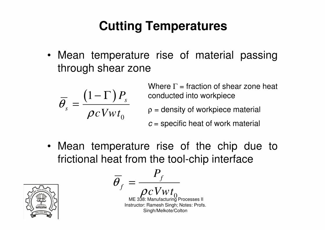
Cutting Temperatures
• Mean temperature rise of material passing
through shear zone
( )
0
1s
s
P
cVwtθ
ρ
− Γ=
Where Γ = fraction of shear zone heat conducted into workpiece
ρ = density of workpiece material
ME 338: Manufacturing Processes II
Instructor: Ramesh Singh; Notes: Profs.
Singh/Melkote/Colton
• Mean temperature rise of the chip due to
frictional heat from the tool-chip interface
0cVwtρc = specific heat of work material
0
f
f
P
cVwtθ
ρ=

Example 2
For the problem in Example 1 calculate the mean temperature
rise in the chip if it is given that the power dissipated into theworkpiece per pass of the tool is 200 W. Assume the density ofmild steel is 7200 kgm-3 and specific heat is 502 Jkg-1K-1. Alsoassume that the cutting tool is insulated and no heat is lost tothe environment.
Solution:
ME 338: Manufacturing Processes II
Instructor: Ramesh Singh; Notes: Profs.
Singh/Melkote/Colton
Solution:
Total cutting power, Pc = Ps + Pf
Insulated tool � no heat goes into tool
Total heat dissipated in the chip = Pc – 200 = 1780 – 200 = 1580 W
Mean temperature rise in chip,
0
1580349.71 KT
cVwtρ∆ = =

Tool Geometry for Single Point Tool
ME 338: Manufacturing Processes II
Instructor: Ramesh Singh; Notes: Profs.
Singh/Melkote/Colton

Wear
• Wear: loss of material from a surface
• Mechanisms
– Adhesive wear
ME 338: Manufacturing Processes II
Instructor: Ramesh Singh; Notes: Profs.
Singh/Melkote/Colton
– Abrasive wear
– Corrosive wear
– Fatigue wear

Adhesive Wear
• Mechanical wear process; wear particles
generated from the softer of two contacting
surfaces; characterized by metal transfer from
softer to harder body
ME 338: Manufacturing Processes II
Instructor: Ramesh Singh; Notes: Profs.
Singh/Melkote/Colton
• Archard’s wear equation:
3
LNV K
H=
K: wear coefficient
V: volume of wear
L: sliding distance
N: normal load
H: hardness of softer surface

Abrasive Wear
• Mechanical wear process; loss of material by micro-cutting action
2-body wear
ME 338: Manufacturing Processes II
Instructor: Ramesh Singh; Notes: Profs.
Singh/Melkote/Colton
• Abrasive wear resistance ∝ hardness
3-body wear

Corrosive Wear
• Chemical wear process; due to chemical
reactions between the surface and
environment (water, oxygen, acids, etc.)
ME 338: Manufacturing Processes II
Instructor: Ramesh Singh; Notes: Profs.
Singh/Melkote/Colton
• Example: solution wear of cemented carbide
cutting tool materials when cutting ferrous
metals at high speeds

Fatigue Wear
• Loss of material from a surface due to
fracture under cyclic loading conditions
– Mechanical fatigue wear: fracture due to cyclic mechanical loads e.g. spalling in roller bearing races
ME 338: Manufacturing Processes II
Instructor: Ramesh Singh; Notes: Profs.
Singh/Melkote/Colton
– Thermal fatigue wear: fracture due to thermal cycling, e.g. hot forging with cool dies
Tool Wear and Tool Life
• Problem of economic importance
• Factors affecting tool wear– Tool material
– Workpiece material
– Cutting conditions
– Tool geometry
ME 338: Manufacturing Processes II
Instructor: Ramesh Singh; Notes: Profs.
Singh/Melkote/Colton
• End of tool life can occur by
– Progressive wear of flank and/or rake face of tool
– Catastrophic failure

Cutting Tool Failure-I
• Progressive wear and catastrophic failure
• Tool Life Criterion determines life of tool
– Flank wear width
– Crater depthWhichever occurs first
ME 338: Manufacturing Processes II
Instructor: Ramesh Singh; Notes: Profs.
Singh/Melkote/Colton
– Crater depth
– Catastrophic failure Whichever occurs first
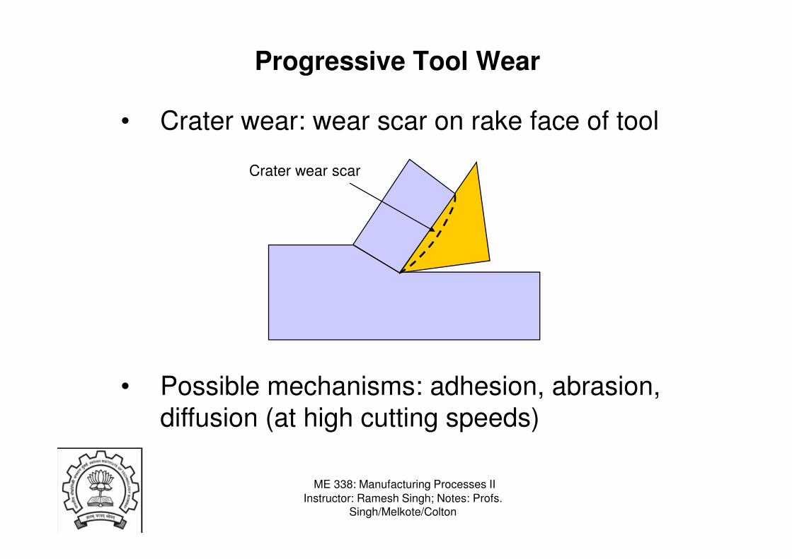
Progressive Tool Wear
• Crater wear: wear scar on rake face of tool
Crater wear scar
ME 338: Manufacturing Processes II
Instructor: Ramesh Singh; Notes: Profs.
Singh/Melkote/Colton
• Possible mechanisms: adhesion, abrasion,
diffusion (at high cutting speeds)

Progressive Tool Wear
• Flank wear: wear scar on flank face of tool
ME 338: Manufacturing Processes II
Instructor: Ramesh Singh; Notes: Profs.
Singh/Melkote/Colton
• Possible mechanisms: adhesion, abrasion
(due to rubbing of flank face against cut
surface)
flank wear scar

ME 338: Manufacturing Processes II
Instructor: Ramesh Singh; Notes: Profs.
Singh/Melkote/Colton
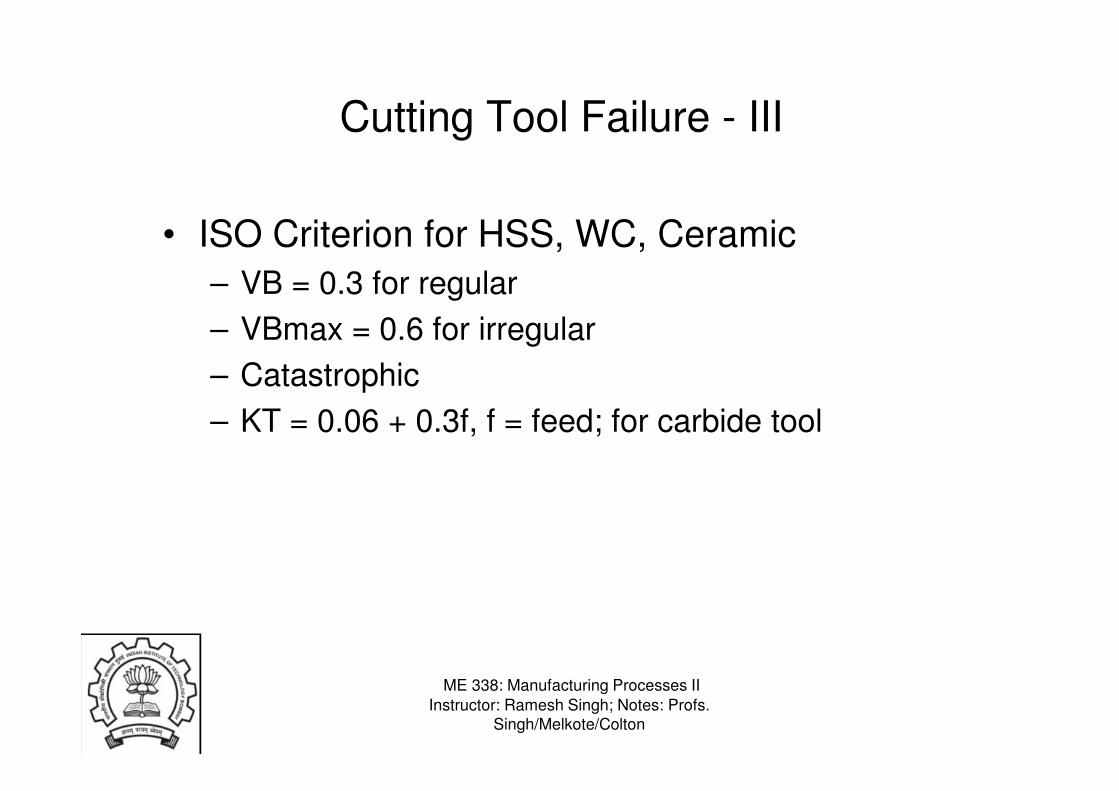
Cutting Tool Failure - III
• ISO Criterion for HSS, WC, Ceramic
– VB = 0.3 for regular
– VBmax = 0.6 for irregular
– Catastrophic
ME 338: Manufacturing Processes II
Instructor: Ramesh Singh; Notes: Profs.
Singh/Melkote/Colton
– KT = 0.06 + 0.3f, f = feed; for carbide tool
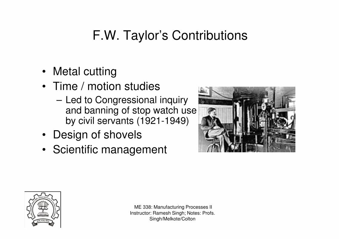
F.W. Taylor’s Contributions
• Metal cutting
• Time / motion studies– Led to Congressional inquiry
and banning of stop watch use by civil servants (1921-1949)
ME 338: Manufacturing Processes II
Instructor: Ramesh Singh; Notes: Profs.
Singh/Melkote/Colton
by civil servants (1921-1949)
• Design of shovels
• Scientific management

Taylor’s Equation
VTn = C
V = cutting speed
T = tool life
n, C = Taylor constants (empirical)
ME 338: Manufacturing Processes II
Instructor: Ramesh Singh; Notes: Profs.
Singh/Melkote/Colton
n, C = Taylor constants (empirical)
log V
C
n
log T1
F.W. Taylor
n For HSS – 0.1; WC-0.2; Ceramics-0.4

Progressive Tool Wear-Flank
• Taylor’s tool life curve VTn = C
ME 338: Manufacturing Processes II
Instructor: Ramesh Singh; Notes: Profs.
Singh/Melkote/Colton

Extended Taylor’s Equation
VTnfm=C’
f = feed rate
• For high speed steels:
ME 338: Manufacturing Processes II
Instructor: Ramesh Singh; Notes: Profs.
Singh/Melkote/Colton
• For high speed steels:
V T 0.24 f 0.45 = 23
T= C’ V -4.2 f -1.9
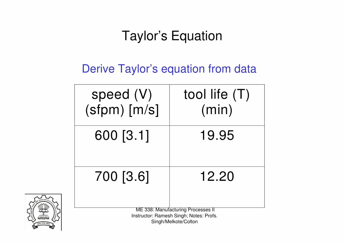
Taylor’s Equation
Derive Taylor’s equation from data
speed (V)(sfpm) [m/s]
tool life (T)(min)
ME 338: Manufacturing Processes II
Instructor: Ramesh Singh; Notes: Profs.
Singh/Melkote/Colton
600 [3.1] 19.95
700 [3.6] 12.20

Taylor’s Equation
• VTn@(600 sfpm) = VTn@(700 sfpm)
• 700(12.2)n = 600(19.95)n
• 700/600 = 1.167 = (19.95/12.2)n
• n ≈ 0.31
ME 338: Manufacturing Processes II
Instructor: Ramesh Singh; Notes: Profs.
Singh/Melkote/Colton
• n ≈ 0.31
• C = 600 x 19.950.31 ≈ 1520
• VT0.31 = 1520

Tool Failure-Crater Wear
– Severe than flank face (Temp, Pressure, wear rate)
– KT can be used as measure
– Taylor like equation can be used
– Tool life due to crater and wearland or flank are
ME 338: Manufacturing Processes II
Instructor: Ramesh Singh; Notes: Profs.
Singh/Melkote/Colton
– Tool life due to crater and wearland or flank are about same

Groove Formation
• Deep grooves occur with high temperature alloys, soft steels (strain hardening)
• Large groove at free edge
• Temperature-Experimental measurement
• Other reasons
ME 338: Manufacturing Processes II
Instructor: Ramesh Singh; Notes: Profs.
Singh/Melkote/Colton
• Other reasons
– Work hardened layer on previously cut material
– Stress concentration due to stress gradient at free surface
– Burr at edge
– Abrasive oxide layer
– Fatigue at edge

Tool Failure-Gross Fracture
– Gross Fracture and Edge Chipping are two failure modes
– Interrupted cutting has severe fracture
– More likely at tool leaving then engaging
• Overshoots the equilibrium unloaded condition
ME 338: Manufacturing Processes II
Instructor: Ramesh Singh; Notes: Profs.
Singh/Melkote/Colton
• Overshoots the equilibrium unloaded condition
• Shear plane rotates assuming negative value results in rapid unloading
• Rate of unloading increase with speed
Tool Failure-Plastic Deformation
• Occurs at High Temperature
• W/P material with poor conductivity
– Temperature accumulation
– Tool tip melting
ME 338: Manufacturing Processes II
Instructor: Ramesh Singh; Notes: Profs.
Singh/Melkote/Colton
– Tool tip melting
– Occurs in Titanium

Tool Wear Cycle
ME 338: Manufacturing Processes II
Instructor: Ramesh Singh; Notes: Profs.
Singh/Melkote/Colton

Tool Wear Cycle and Maps
• Initial Wear Mechanisms
– Initial contact between two surfaces
– Stresses/heat are intensified at contact with fracture and melting of asperities
– Surface contact increases and visible wear marks
ME 338: Manufacturing Processes II
Instructor: Ramesh Singh; Notes: Profs.
Singh/Melkote/Colton
– Surface contact increases and visible wear marks

Wear cycle
• Steady State Wear – Velocity and normal stress remain stable
– Crater wear due to diffusion due to transfer of atoms
– BUE formed in some cases; fracture causes
ME 338: Manufacturing Processes II
Instructor: Ramesh Singh; Notes: Profs.
Singh/Melkote/Colton
– BUE formed in some cases; fracture causes attritious/adhesive wear
– Chipping in case of discontinuous chips
– Crack initiation and propagation due to cyclic loading
– Stable abrasion
Wear Cycle
• Tertiary Wear
– Wear surfaces enlarges to critical size and wear accelerates
– Wear resistant coatings separate causing
accelerated wear
ME 338: Manufacturing Processes II
Instructor: Ramesh Singh; Notes: Profs.
Singh/Melkote/Colton
accelerated wear
– Rapid diffusion/local seizure and melting

Tool Wear Maps
• Mechanisms under different velocities, contact pressures and feed rate
• At low velocities BUE and adhesion
• Very high velocity diffusion/oxidation
ME 338: Manufacturing Processes II
Instructor: Ramesh Singh; Notes: Profs.
Singh/Melkote/Colton
• At low velocity and high normal pressure seizure takes place
• Safe limits for cratering and fracture can be determined for a combination of tool and W/P.

Tool Wear Mechanisms
Low speed High speed Very high speed
ME 338: Manufacturing Processes II
Instructor: Ramesh Singh; Notes: Profs.
Singh/Melkote/Colton
Mechanicalproperties
Chemical diffusion andconvection
Chemicaldiffusion
Wear at Low Speeds
Mechanical Properties
– flow induced crack nucleation and growth
– micro fracture
– fatigue
ME 338: Manufacturing Processes II
Instructor: Ramesh Singh; Notes: Profs.
Singh/Melkote/ColtonME 6222: Manufacturing
Processes and Systems Prof. J.S. Colton © GIT
69
– fatigue
– abrasion
• Al2O3 at all speeds
– cutting steel and Ni
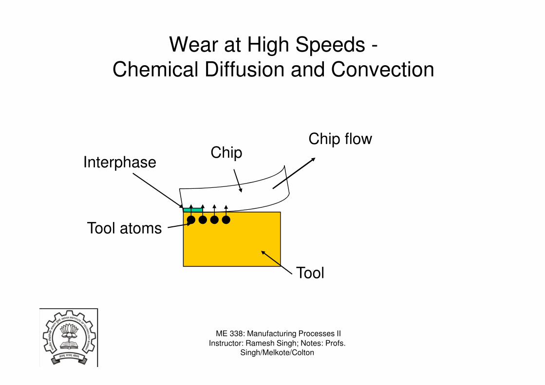
Wear at High Speeds -Chemical Diffusion and Convection
ChipChip flow
Interphase
ME 338: Manufacturing Processes II
Instructor: Ramesh Singh; Notes: Profs.
Singh/Melkote/Colton
Tool atoms
Tool

Chemical Diffusion and Convection
• Tool dissolves directly into chip
• Convection - chip sliding on surface
– transition between sliding and sticking begins
– maximum heat generation point moves away
from tool tip
ME 338: Manufacturing Processes II
Instructor: Ramesh Singh; Notes: Profs.
Singh/Melkote/Colton
from tool tip
• Net flow of material away from interface
Wear at High Speeds
• Carbides - super alloys, hard steels
• Al2O3 - Ti
• Carbides, nitrides - steels
• CBN - steels
ME 338: Manufacturing Processes II
Instructor: Ramesh Singh; Notes: Profs.
Singh/Melkote/ColtonME 6222: Manufacturing
Processes and Systems Prof. J.S. Colton © GIT
72
• CBN - steels
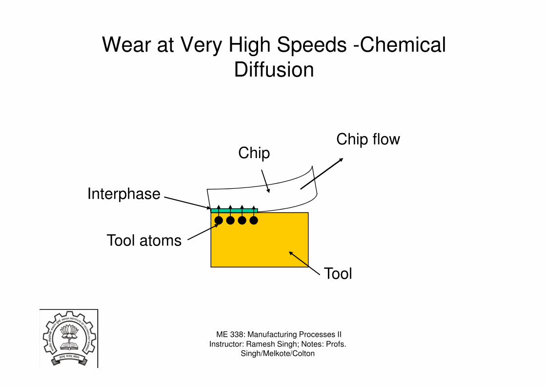
Wear at Very High Speeds -Chemical Diffusion
ChipChip flow
Interphase
ME 338: Manufacturing Processes II
Instructor: Ramesh Singh; Notes: Profs.
Singh/Melkote/Colton
Tool atoms
Tool
Interphase

Chemical Diffusion
• Transition from sliding to sticking moves
from the nose
– finally sticking occurs everywhere
• Boundary layer builds up
ME 338: Manufacturing Processes II
Instructor: Ramesh Singh; Notes: Profs.
Singh/Melkote/Colton
74
– no convection directly from tool to chip
– only chemical diffusion through boundary layer of chip material
Wear at Very High Speeds
• Carbide, diamond - Ti at all speeds
• CBN - super alloys, hard steels
ME 338: Manufacturing Processes II
Instructor: Ramesh Singh; Notes: Profs.
Singh/Melkote/Colton
ChipChip flow
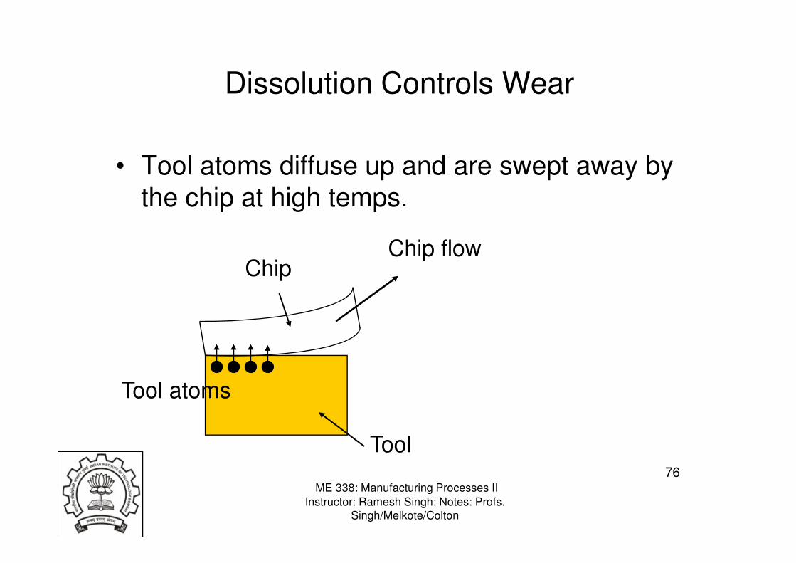
Dissolution Controls Wear
• Tool atoms diffuse up and are swept away by
the chip at high temps.
ME 338: Manufacturing Processes II
Instructor: Ramesh Singh; Notes: Profs.
Singh/Melkote/Colton
76
Tool atoms
Tool

Wear Velocity (vwear)
• k =
• c = equilibrium solubility
y
ckDkcvv ywear
∂
∂−=
)(
)(
chip
tool
VmaterialchipofvolumeMolar
VmaterialtoolofvolumeMolar
ME 338: Manufacturing Processes II
Instructor: Ramesh Singh; Notes: Profs.
Singh/Melkote/Colton
77
• vy = ⊥ bulk velocity of chip at chip-tool
interface
• D = chemical diffusivity
• = concentration gradient
y
c
∂
∂

Choosing Machining Conditions
• Pick maximum possible depth of cut
• Take maximum feed rate subject to:
– surface finish (see next slides)
– power limitations of machine
ME 338: Manufacturing Processes II
Instructor: Ramesh Singh; Notes: Profs.
Singh/Melkote/Colton
– power limitations of machine
• If you’re power limited, are chips breaking?
• Chips break at f > 0.005”/min (0.13 mm/min)
• Pick cost optimum speed (from Taylor’s Eqn)
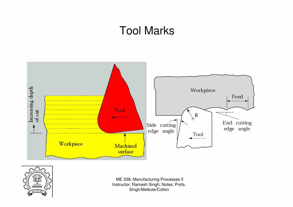
Tool Marks
ME 338: Manufacturing Processes II
Instructor: Ramesh Singh; Notes: Profs.
Singh/Melkote/Colton

(b)(a)
Surface Marks
ME 338: Manufacturing Processes II
Instructor: Ramesh Singh; Notes: Profs.
Singh/Melkote/Colton
Surfaces produced on steel by cutting, as observed with a scanning electron microscope: (a) turned surface and (b) surface produced by shaping. Source: J. T. Black and S. Ramalingam.

Roughness
f = feedr
fRoughnessAA
318
2
≈r
fRoughnesst
8
2
≈
ME 338: Manufacturing Processes II
Instructor: Ramesh Singh; Notes: Profs.
Singh/Melkote/Colton
f = feed
r = nose radius
AA = arithmetic average
t = peak-to-valley r
f
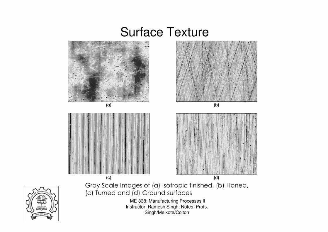
Surface Texture
(a) (b)(a) (b)
ME 338: Manufacturing Processes II
Instructor: Ramesh Singh; Notes: Profs.
Singh/Melkote/Colton
(c) (d)(c) (d)
Gray Scale Images of (a) Isotropic finished, (b) Honed,
(c) Turned and (d) Ground surfaces

Surface Texture
• Definition: Periodic and/or random deviations
of a real surface from the nominal surface.
ME 338: Manufacturing Processes II
Instructor: Ramesh Singh; Notes: Profs.
Singh/Melkote/Colton
Isotropic Surface: random Turned Surface: Periodic

Tool Material Properties
• Main requirements
– Elevated temperature hardness (“hot hardness”)
– Toughness
ME 338: Manufacturing Processes II
Instructor: Ramesh Singh; Notes: Profs.
Singh/Melkote/Colton
– High wear resistance

Cutting Tools
• 1923: Schroter
– WC + Co
• Co wets WC and binds together
• Cemented carbide structure
– Twice the speed of WC
– Not as tough as HSS
WC1-3 µm
ME 338: Manufacturing Processes II
Instructor: Ramesh Singh; Notes: Profs.
Singh/Melkote/Colton
– Not as tough as HSS
• fine grain structure helps
– Machine vibration is problem
• rigid machines help
– Solubility of WC in Fe ≈ 5% Co in between

Cutting Tools
• 1931: Complex carbides developed
– TiC added to increase chemical stability
– 2x the cutting speed of WC + Co
– lower strength
ME 338: Manufacturing Processes II
Instructor: Ramesh Singh; Notes: Profs.
Singh/Melkote/Colton
– increased wear resistance
Cutting Tools
• 1960’s: Increased cutting speeds
• Powder metallurgy
– production of carbide inserts
– disposable inserts, no resharpening
– coatings feasible: TiC, TiN, Al O
ME 338: Manufacturing Processes II
Instructor: Ramesh Singh; Notes: Profs.
Singh/Melkote/Colton
– coatings feasible: TiC, TiN, Al2O3
• ≈ 5 µm layer to minimize strain
• very wear resistant
• 50-70% of tool life expended before coating penetrated

Tool Coatings
ME 338: Manufacturing Processes II
Instructor: Ramesh Singh; Notes: Profs.
Singh/Melkote/Colton

Cutting Tools
• Optimization of bonding between coating and
substrate
ME 338: Manufacturing Processes II
Instructor: Ramesh Singh; Notes: Profs.
Singh/Melkote/Colton
WC+Co
TiC
TiN
Al2O3
TiN

Cutting Tools
• Aluminum oxide (Al2O3)
– wear resistant, but low strength
• Al2O3 + 30% TiC: hot-pressed
– increased strength 15-30%
ME 338: Manufacturing Processes II
Instructor: Ramesh Singh; Notes: Profs.
Singh/Melkote/Colton
– increased strength 15-30%
– higher speeds - 3-5x of carbides

Cutting Tools
• Si3N4
– high toughness in bulk form
– low thermal expansion
– not for steel, dissolves - fast wear
ME 338: Manufacturing Processes II
Instructor: Ramesh Singh; Notes: Profs.
Singh/Melkote/Colton
• Al2O3 + Si3N4 (SiAlON)
– cuts Ni superalloys and steels

Cutting Tools
• Diamond (C)
– HB ≈10,000 kg/mm2
– soluble in steel
– good for aluminumWC
diamonds
1 mm
ME 338: Manufacturing Processes II
Instructor: Ramesh Singh; Notes: Profs.
Singh/Melkote/Colton
– good for aluminum
– good for Si-Al alloys
– 10-40 µm particles are sintered onto a WC substrate ⇒ polycrystalline tool
Cutting Tools
• Cubic Boron Nitride (CBN)
– more stable with respect to steel and Ni
– HB ≈ 4,500 kg/mm2
– cuts very hard steels (10x carbide)
– cuts Ni-based super alloys (10x carbide)
ME 338: Manufacturing Processes II
Instructor: Ramesh Singh; Notes: Profs.
Singh/Melkote/Colton
– cuts Ni-based super alloys (10x carbide)
– wears quickly at low speeds, only good at high speeds

Tool Materials
1. High Speed Steel (HSS)
2. Carbide (WC)
3. Ceramics (Al2O3)
Hot hard
ness
Wear
resis
tance
Toughness
ME 338: Manufacturing Processes II
Instructor: Ramesh Singh; Notes: Profs.
Singh/Melkote/Colton
4. Polycrystalline Diamond (PCD)/
Cubic Boron Nitride (CBN)
5. Single Crystal Diamond (SCD)
Hot hard
ness
Wear
resis
tance
Toughness
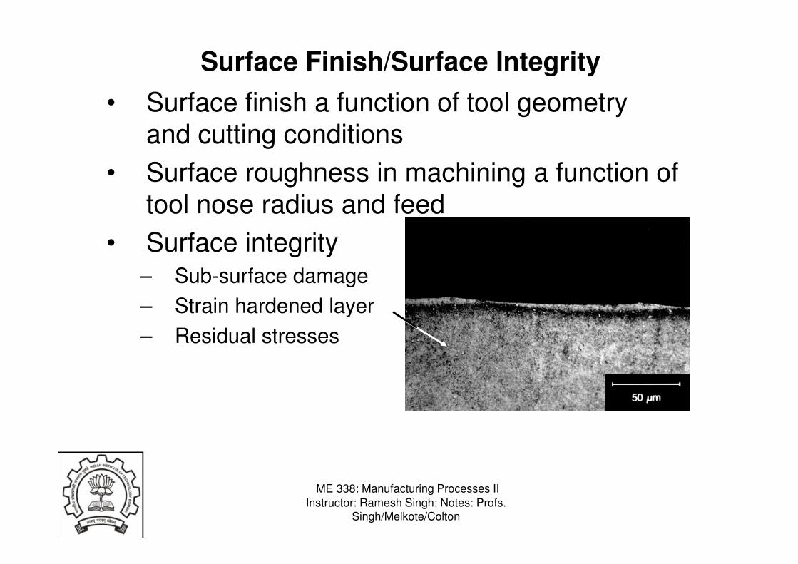
Surface Finish/Surface Integrity
• Surface finish a function of tool geometry
and cutting conditions
• Surface roughness in machining a function of
tool nose radius and feed
• Surface integrity– Sub-surface damage
ME 338: Manufacturing Processes II
Instructor: Ramesh Singh; Notes: Profs.
Singh/Melkote/Colton
– Sub-surface damage
– Strain hardened layer
– Residual stresses

Summary
• Shaping & planing
• Turning
• Milling
• Orthogonal vs. oblique cutting
• Chip formation
ME 338: Manufacturing Processes II
Instructor: Ramesh Singh; Notes: Profs.
Singh/Melkote/Colton
• Chip formation
• Kinematics and mechanics of orthogonal cutting
• Temperature analysis
• Tool wear and tool life
• Surface integrity


