Conveyor system XW Contents FlexLink conveyor system XW 2 Technical data 3 Design guidelines 4 Installation procedure 6 Chains 8 Conveyor frame components 10 Drive units 12 Double drive units 14 Triple drive units 16 Idler end units 18 Support designs 20 PO TR XS XL XM XH XK XB XW CA PAL XC XD XF XR FST APX IDX FlexLink XW 1
Transcript
Conveyor system XW
ContentsFlexLink conveyor system XW 2Technical data 3Design guidelines 4Installation procedure 6Chains 8Conveyor frame components 10Drive units 12Double drive units 14Triple drive units 16Idler end units 18Support designs 20
PO
TR
XS
XL
XM
XH
XK
XB
XW
CA
PAL
XC
XD
XF
XR
FST
APX
IDX
FlexLink XW 1
FlexLink conveyor system XW
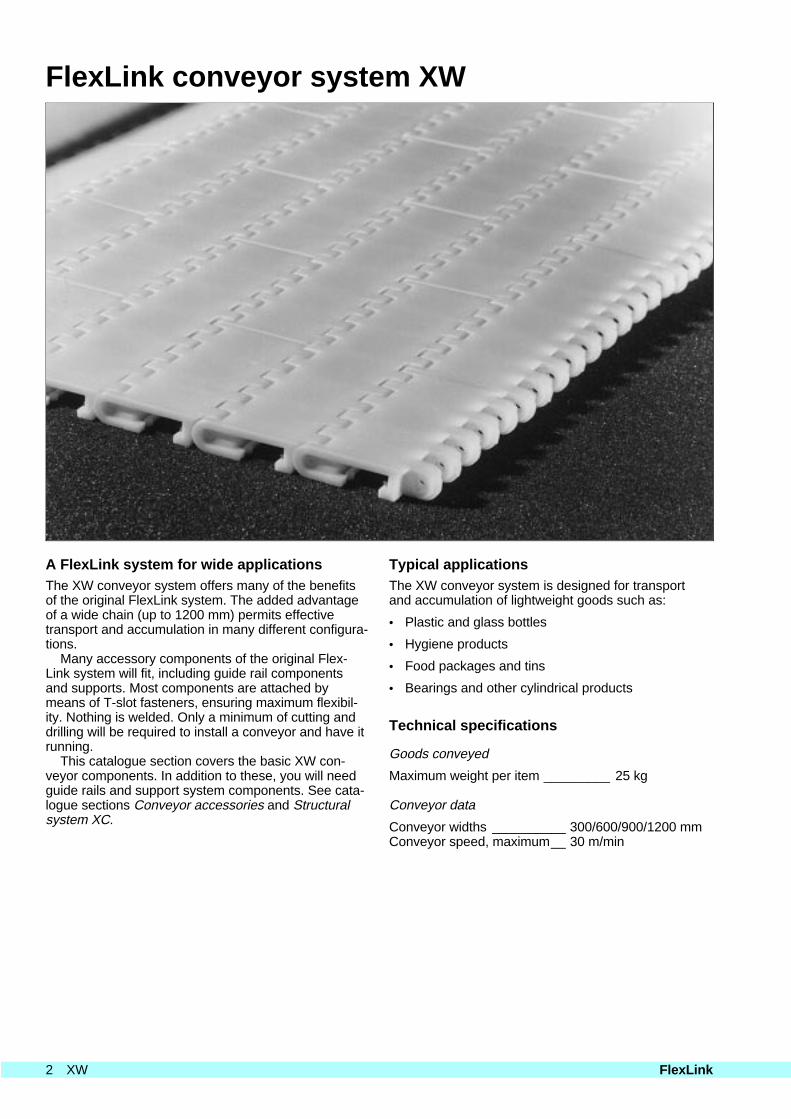
A FlexLink system for wide applicationsThe XW conveyor system offers many of the benefitsof the original FlexLink system. The added advantageof a wide chain (up to 1200 mm) permits effectivetransport and accumulation in many different configura-tions.
Many accessory components of the original Flex-Link system will fit, including guide rail componentsand supports. Most components are attached bymeans of T-slot fasteners, ensuring maximum flexibil-ity. Nothing is welded. Only a minimum of cutting anddrilling will be required to install a conveyor and have itrunning.
This catalogue section covers the basic XW con-veyor components. In addition to these, you will needguide rails and support system components. See cata-logue sections Conveyor accessories and Structuralsystem XC.
Typical applicationsThe XW conveyor system is designed for transportand accumulation of lightweight goods such as:
Polyethylene slide rail UHMW-PEXWCR 25 U new _____________________ 0,10–0,15XWCR 25 U after wear-in ______________ 0,20–0,25
The coefficient of friction is normally at the lower valueat startup of a new conveyor. It will increase as thecontact surfaces are wearing in. Lubrication will reducethe coefficient of friction.
Friction between chain and product
In most cases, the coefficient of friction for contact be-tween plain chain and product is between 0,1 and0,35. Always measure the friction between the chainand the actual product. The actual friction coefficientsdepend on the material and on the surface smooth-ness.
Temperature limitsFlexLink can operate continuously between –20 °Cand +60 °C. Temperatures up to 100 °C can be toler-ated for short periods (cleaning, rinsing).
Due to linear expansion, a conveyor must not oper-ate at temperature changes exceeding 30° without ad-justment of the structure width.
Effective track lengthsThe following table lists the effective track lengths fordrive units and idler end units. These should be consid-ered when determining how much conveyor chain is re-quired in a system.
Description Effective track length
Standard drive unit 850 mm
Idler end unit 850 mm
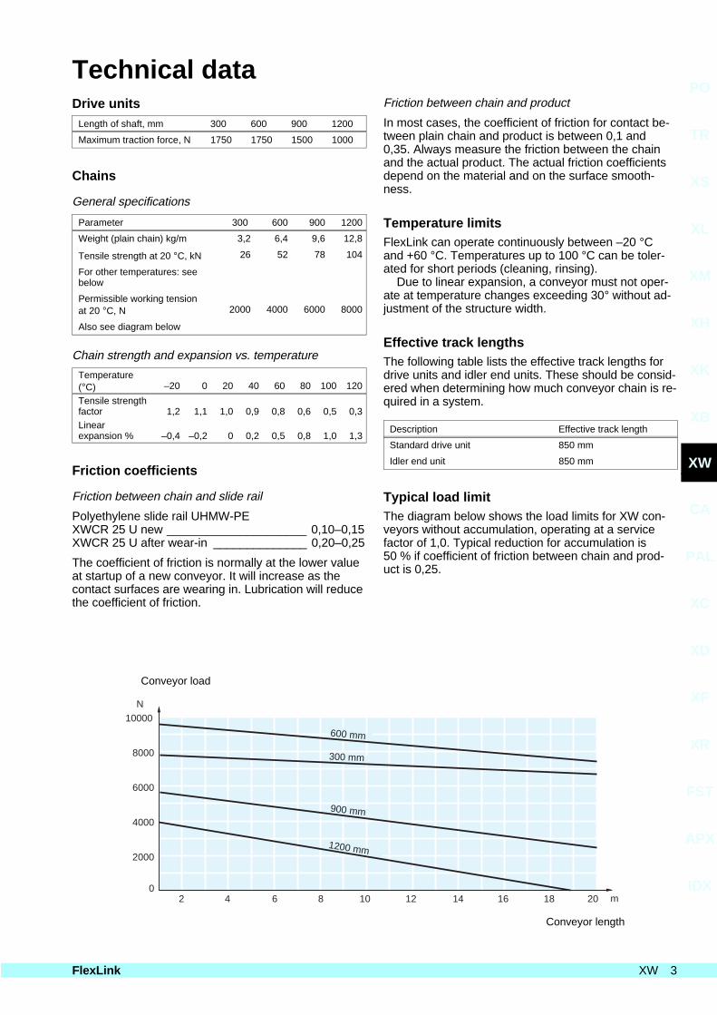
Typical load limitThe diagram below shows the load limits for XW con-veyors without accumulation, operating at a servicefactor of 1,0. Typical reduction for accumulation is50 % if coefficient of friction between chain and prod-uct is 0,25.
0
2000
4000
6000
8000
10000
2 4 6 8 10 12 14 16 18 20 m
1200 mm
900 mm
300 mm
600 mm
N
Conveyor load
Conveyor length
PO
TR
XS
XL
XM
XH
XK
XB
XW
CA
PAL
XC
XD
XF
XR
FST
APX
IDX
FlexLink XW 3
Design guidelinesDesign procedureAs in all design work it is essential to base the work ona specification of design requirements. Parameters totake into consideration include:
• Surface pressure between chain and slide rail
• Load on conveyor
• Conveyor width
• Total length
• Conveyor speed
• Operating temperature
Layout considerations
The layout must ensure that the load is well distributedacross the total width of the conveyor. The maximumload specification applies to a well distributed load.
It is important to minimize the total length of the con-veyor. If the length versus total load exceeds the rec-ommended value (see the diagram on page 3), theconveyor must be divided into two. If the applied loadis heavier than recommended, please contact FlexLinkSystems for alternative solutions.
Temperature
The plastic material used in the chain has a greaterthermal expansion than the aluminium framework. Thismeans that it is necessary to take thermal expansioninto consideration when building and assembling theconveyor. If possible, the conveyor should be built atthe final location, and in the environmental tempera-ture typical of the operating environment.
Support system design
The XW conveyor can be used in many different appli-cations and environments. This means that the require-ments of the support structure will be very differentfrom one application to another. The FlexLink productprogramme includes a comprehensive line of suitablesupport components, including beams, connectinghardware, feet, etc. A number of typical support solu-tions are presented on page 20. For more information,see catalogue section Structural system XC.
Guide rail design
The XW conveyor is designed for use with standardFlexLink guide rail components. For more information,see catalogue section Conveyor accessories.
Parts list
When you are satisfied with your layout, including sup-port and guide rail components, you can easily com-pile a list of the parts required to build the conveyor. Ifyou need additional information, do not hesitate to con-tact FlexLink Systems.
Chain tension calculationsWhy calculate?
There are at least two reasons why you should esti-mate or calculate the maximum tension of the chain be-fore you decide on a conveyor configuration:
• Drive unit capacity
• Tension limit of conveyor chain
Drive unit capacity limit/chain tension limit
The required drive motor output power P depends on
• Traction force F [N]
• Chain speed v [m/min]
The following equations apply:
P [W] = 1/60 ⋅ F ⋅ v
or
P [W] = 1/9550 ⋅ F ⋅ r ⋅ n
where r is the drive sprocket wheel radius in mm, andn is the rotational speed of the sprocket wheel in r.p.m.
Service factor
The maximum permissible chain tension depends onthe number of conveyor starts and stops per hour.Many conveyors run continuously, whereas othersstart and stop frequently. It is obvious that frequentstarts and stops increase the stress on the chain andon the drive unit.
The service factor (see table below) is used to der-ate for high frequency of starts and stops and for highchain speeds. Divide the tension limit obtained fromthe graphs by the service factor to get the derated ten-sion limit. A high service factor can be reduced by pro-viding a soft start/stop function.
Operating conditions Service factor
Low to moderate speedor max. 1 start/stop per hour 1,0
Max 10 starts/stops per hour 1,2
Max. 30 starts/stops per hour 1,4
High speed, heavy load or more than 30 starts/stops per hour 1,6
Drive unit clutch adjustment
The slip clutch of the drive unit must be adjusted for atraction force lower than or equal to the calculatedchain load limit, with the service factor taken into con-sideration.
4 XW FlexLink
Design guidelines
Traction force
The tension building up in the chain can be dividedinto several components:
1 Friction between loaded chain and slide rails.
2 Friction between accumulating products and topsurface of chain.
3 Friction between unloaded chain and slide rails, forexample on the underside of the conveyor beam.
The traction force F required to move the chain de-pends on the following factors:
Conveyor length______________________ LProduct gravity load per m Transport __________________________ qp Accumulation _______________________ qpaChain gravity load per m _______________ qcFriction coefficient Between chain and slide rail ___________ µr Between chain and products ___________ µp
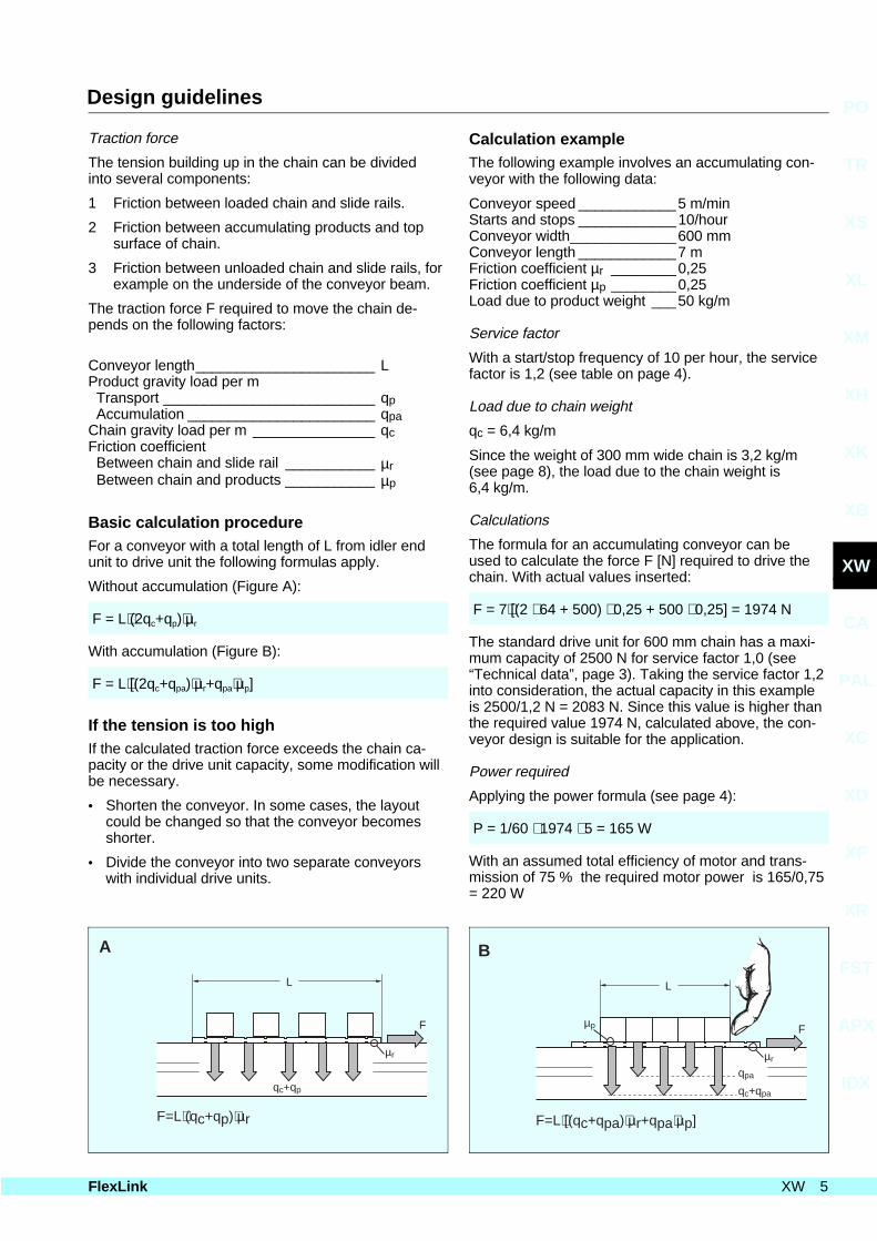
Basic calculation procedureFor a conveyor with a total length of L from idler endunit to drive unit the following formulas apply.
Without accumulation (Figure A):
F = L⋅(2qc+qp)⋅µr
With accumulation (Figure B):
F = L⋅[(2qc+qpa)⋅µr+qpa⋅µp]
If the tension is too highIf the calculated traction force exceeds the chain ca-pacity or the drive unit capacity, some modification willbe necessary.
• Shorten the conveyor. In some cases, the layoutcould be changed so that the conveyor becomesshorter.
• Divide the conveyor into two separate conveyorswith individual drive units.
Calculation exampleThe following example involves an accumulating con-veyor with the following data:
Conveyor speed ____________5 m/minStarts and stops ____________10/hourConveyor width_____________600 mmConveyor length ____________7 mFriction coefficient µr ________0,25Friction coefficient µp ________0,25Load due to product weight ___50 kg/m
Service factor
With a start/stop frequency of 10 per hour, the servicefactor is 1,2 (see table on page 4).
Load due to chain weight
qc = 6,4 kg/m
Since the weight of 300 mm wide chain is 3,2 kg/m(see page 8), the load due to the chain weight is6,4 kg/m.
Calculations
The formula for an accumulating conveyor can beused to calculate the force F [N] required to drive thechain. With actual values inserted:
F = 7⋅[(2 ⋅ 64 + 500) ⋅ 0,25 + 500 ⋅ 0,25] = 1974 N
The standard drive unit for 600 mm chain has a maxi-mum capacity of 2500 N for service factor 1,0 (see“Technical data”, page 3). Taking the service factor 1,2into consideration, the actual capacity in this exampleis 2500/1,2 N = 2083 N. Since this value is higher thanthe required value 1974 N, calculated above, the con-veyor design is suitable for the application.
Power required
Applying the power formula (see page 4):
P = 1/60 ⋅ 1974 ⋅ 5 = 165 W
With an assumed total efficiency of motor and trans-mission of 75 % the required motor power is 165/0,75= 220 W
L
q +qc p
µr
F
F=L (qc+qp) r⋅ ⋅µ
A
L
q +qc pa
µr
µp F
F=L [(qc+qpa) r+qpa p]⋅ ⋅µ ⋅µ
B
qpa
PO
TR
XS
XL
XM
XH
XK
XB
XW
CA
PAL
XC
XD
XF
XR
FST
APX
IDX
FlexLink XW 5
Installation procedureIntroductionThe method of building an XW conveyor consists ofthe following basic steps:
• Build the conveyor frame structure on the floor, ex-cluding drive unit and idler end unit.
• Attach vertical support legs and feet to the con-veyor, to place it at the planned height.
• Install drive unit and idler end unit.
• Install slide rail. See Appendix A in catalogue sec-tion APX for instructions on anchoring the slide rail.The same information is also available separatelyas a pamphlet (Publication 4263).
• Install the conveyor chain.
• Test the conveyor and adjust the slip clutch.
Preparations1 Ensure that all materials and components required
for the installation are available at the site. Checkwith the parts list.
2 Ensure that the necessary tools are available:No.13 wrench, knife, ∅4,2 drill, drilling machine.
Assembly of frame sectionThe cross bar connects the two frame profiles to forma conveyor frame. Standard FlexLink light supportbeam XCBL 3×44 is used for this purpose.
Use four cross bars for every 3 m length of framesection.
Assemble a 3 m straight section as follows:
1 Cut the cross bar beam (90°) to four lengths. Cutting length: see Table 1.
Drill holes if fastener yokes XCAF 44 will be used.
2 Attach four angle brackets XLFA 44 C or two fas-tener yokes XCAF 44 to the ends of the crossbars. Fastener yokes will provide a cost-effective,yet very rigid connection. Angle brackets permitsome adjustment of the frame width, to compen-sate for errors in beam length and angle.
3 Connect the cross bar assembly to the two frameprofiles. Tighten well on one side.
4 Measure the outside frame width and adjust asnecessary. Then tighten all screws permanently.Outer frame width: see Table 1.
5 Install minimum one centre support profileXWCN 3, using hold-down bracket XWCP 20 to at-tach it to the cross bar. The number of centre sup-port profiles depends on the load.
Note. The centre support profile must extend intothe drive unit and idler end unit, up to thedrive/idler wheel centre. See photo on page 18.
Do not install slide rails until after completion of theconveyor frame.
Basic conveyor structure1 Assemble the basic conveyor by connecting con-
veyor frame sections using connecting stripsXWCJ 6×280 in the inner slot of the frame profile.(The outer slots should be reserved for connectionto the support system, and for other external con-nections.) Use connecting pieces XLRJ 100 to con-nect the centre support profiles.
2 Connect support legs and feet to your basic con-veyor in accordance with your layout. Try to locatesupport points close to joints between frame sec-tions.
3 Install drive unit and idler end unit. Note that theyboth come with connecting strips included.
Table 1. Frame section dimensions
Nominal chainwidth (mm)
Actual chainwidth (mm)
Crossbarlength (mm)
Frame outerwidth (mm)
300 299 259 ±0,5 303
600 597 557 ±0,5 601
2×300 – 561 ±0,5 605
900 896 857 ±0,5 901
3×300 – 862 ±0,5 906
1200 1195 1155 ±0,5 1199
6 XW FlexLink
Installation procedure
Slide rail and chain1 Install plastic slide rail on all profiles that would oth-
erwise be in direct contact with the chain.
2 Secure the slide rails with two plastic screwsXWAG 5. See Appendix A, catalogue section APX.
3 Release the friction coupling (slip clutch) so thatthe drive shaft is free to turn.
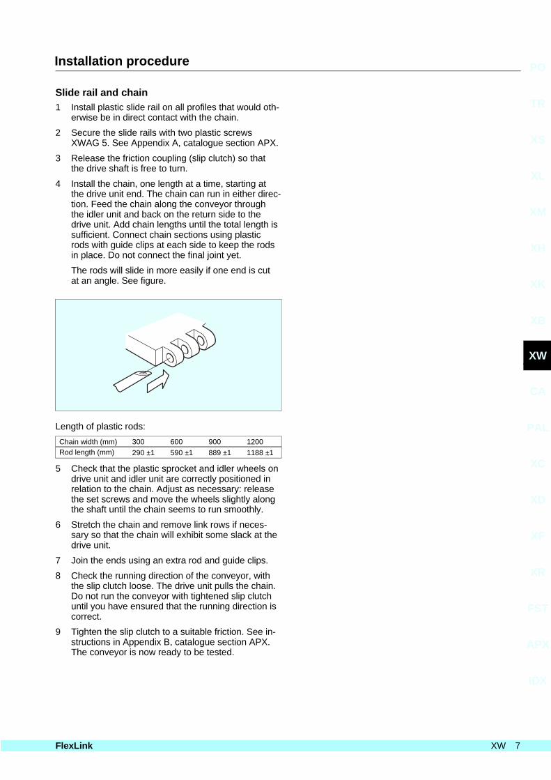
4 Install the chain, one length at a time, starting atthe drive unit end. The chain can run in either direc-tion. Feed the chain along the conveyor throughthe idler unit and back on the return side to thedrive unit. Add chain lengths until the total length issufficient. Connect chain sections using plasticrods with guide clips at each side to keep the rodsin place. Do not connect the final joint yet.
The rods will slide in more easily if one end is cutat an angle. See figure.
5 Check that the plastic sprocket and idler wheels ondrive unit and idler unit are correctly positioned inrelation to the chain. Adjust as necessary: releasethe set screws and move the wheels slightly alongthe shaft until the chain seems to run smoothly.
6 Stretch the chain and remove link rows if neces-sary so that the chain will exhibit some slack at thedrive unit.
7 Join the ends using an extra rod and guide clips.
8 Check the running direction of the conveyor, withthe slip clutch loose. The drive unit pulls the chain.Do not run the conveyor with tightened slip clutchuntil you have ensured that the running direction iscorrect.
9 Tighten the slip clutch to a suitable friction. See in-structions in Appendix B, catalogue section APX.The conveyor is now ready to be tested.
PO
TR
XS
XL
XM
XH
XK
XB
XW
CA
PAL
XC
XD
XF
XR
FST
APX
IDX
FlexLink XW 7
Chains
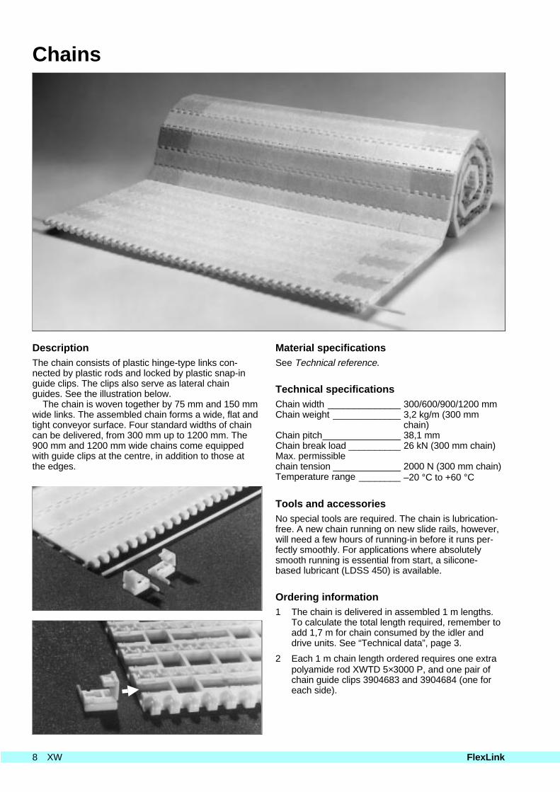
DescriptionThe chain consists of plastic hinge-type links con-nected by plastic rods and locked by plastic snap-inguide clips. The clips also serve as lateral chainguides. See the illustration below.
The chain is woven together by 75 mm and 150 mmwide links. The assembled chain forms a wide, flat andtight conveyor surface. Four standard widths of chaincan be delivered, from 300 mm up to 1200 mm. The900 mm and 1200 mm wide chains come equippedwith guide clips at the centre, in addition to those atthe edges.
chain)Chain pitch_______________ 38,1 mmChain break load __________ 26 kN (300 mm chain)Max. permissiblechain tension _____________ 2000 N (300 mm chain)Temperature range ________ –20 °C to +60 °C
Tools and accessoriesNo special tools are required. The chain is lubrication-free. A new chain running on new slide rails, however,will need a few hours of running-in before it runs per-fectly smoothly. For applications where absolutelysmooth running is essential from start, a silicone-based lubricant (LDSS 450) is available.
Ordering information1 The chain is delivered in assembled 1 m lengths.
To calculate the total length required, remember toadd 1,7 m for chain consumed by the idler anddrive units. See “Technical data”, page 3.
2 Each 1 m chain length ordered requires one extrapolyamide rod XWTD 5×3000 P, and one pair ofchain guide clips 3904683 and 3904684 (one foreach side).
8 XW FlexLink
299
991
12
597
991
896
991
1195
991
4,4
24
3904683
24
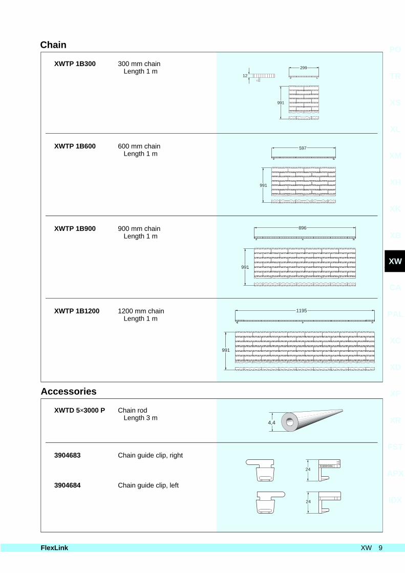
Chain
XWTP 1B300 300 mm chainLength 1 m
XWTP 1B600 600 mm chainLength 1 m
XWTP 1B900 900 mm chainLength 1 m
XWTP 1B1200 1200 mm chainLength 1 m
Accessories
XWTD 5×3000 P Chain rodLength 3 m
3904683 Chain guide clip, right
3904684 Chain guide clip, left
PO
TR
XS
XL
XM
XH
XK
XB
XW
CA
PAL
XC
XD
XF
XR
FST
APX
IDX
FlexLink XW 9
Conveyor frame components
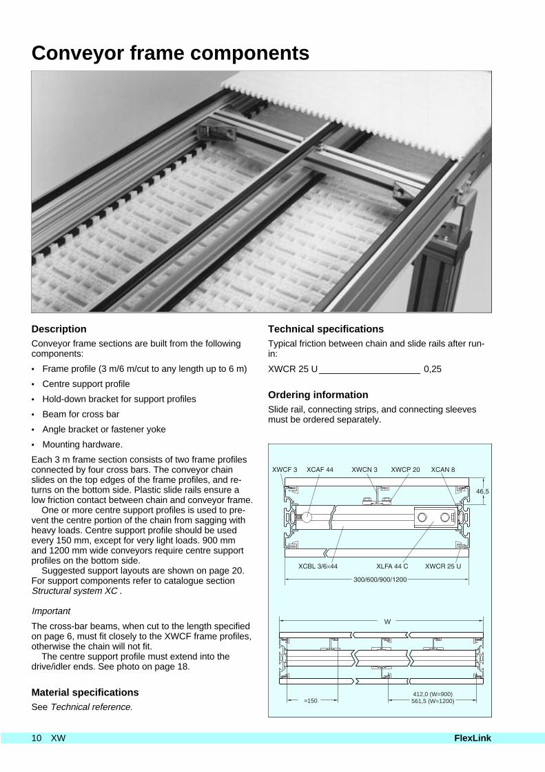
DescriptionConveyor frame sections are built from the followingcomponents:
• Frame profile (3 m/6 m/cut to any length up to 6 m)
• Centre support profile
• Hold-down bracket for support profiles
• Beam for cross bar
• Angle bracket or fastener yoke
• Mounting hardware.
Each 3 m frame section consists of two frame profilesconnected by four cross bars. The conveyor chainslides on the top edges of the frame profiles, and re-turns on the bottom side. Plastic slide rails ensure alow friction contact between chain and conveyor frame.
One or more centre support profiles is used to pre-vent the centre portion of the chain from sagging withheavy loads. Centre support profile should be usedevery 150 mm, except for very light loads. 900 mmand 1200 mm wide conveyors require centre supportprofiles on the bottom side.
Suggested support layouts are shown on page 20.For support components refer to catalogue sectionStructural system XC .
Important
The cross-bar beams, when cut to the length specifiedon page 6, must fit closely to the XWCF frame profiles,otherwise the chain will not fit.
The centre support profile must extend into thedrive/idler ends. See photo on page 18.
Material specificationsSee Technical reference.
Technical specificationsTypical friction between chain and slide rails after run-in:
XWCR 25 U____________________ 0,25
Ordering informationSlide rail, connecting strips, and connecting sleevesmust be ordered separately.
W
412,0 (W=900)561,5 (W=1200)≈150
10 XW FlexLink
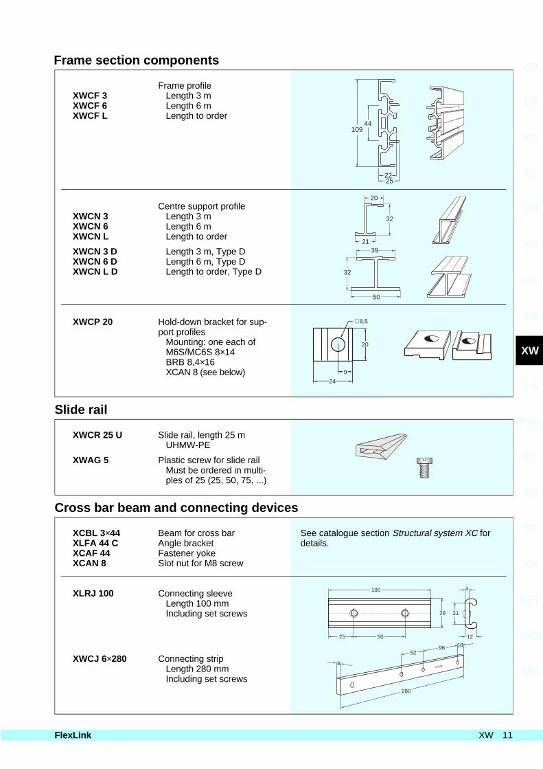
Frame section components
Frame profileXWCF 3XWCF 6XWCF L
Length 3 mLength 6 mLength to order
Centre support profileXWCN 3XWCN 6XWCN L
Length 3 mLength 6 mLength to order
XWCN 3 DXWCN 6 DXWCN L D
Length 3 m, Type DLength 6 m, Type DLength to order, Type D
XWCP 20 Hold-down bracket for sup-port profiles
Mounting: one each ofM6S/MC6S 8×14BRB 8,4×16XCAN 8 (see below)
Slide rail
XWCR 25 U Slide rail, length 25 mUHMW-PE
XWAG 5 Plastic screw for slide railMust be ordered in multi-ples of 25 (25, 50, 75, ...)
Cross bar beam and connecting devices
XCBL 3×44XLFA 44 CXCAF 44XCAN 8
Beam for cross barAngle bracketFastener yokeSlot nut for M8 screw
See catalogue section Structural system XC fordetails.
XLRJ 100 Connecting sleeveLength 100 mmIncluding set screws
XWCJ 6×280 Connecting stripLength 280 mmIncluding set screws
20
32
21
32
50
39
∅8,5
20
9
24
100
25 50 12
4
29 21
6
5296 18
280
44109
2225
PO
TR
XS
XL
XM
XH
XK
XB
XW
CA
PAL
XC
XD
XF
XR
FST
APX
IDX
FlexLink XW 11
Drive units
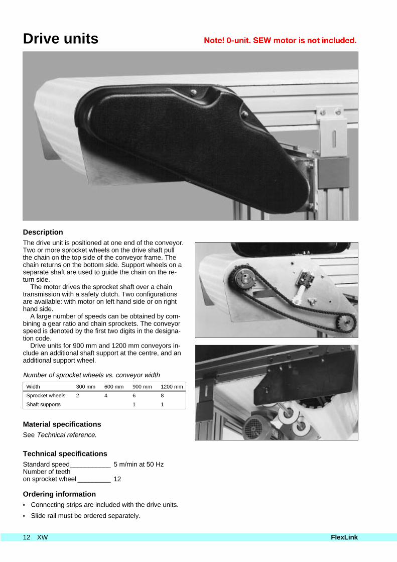
DescriptionThe drive unit is positioned at one end of the conveyor.Two or more sprocket wheels on the drive shaft pullthe chain on the top side of the conveyor frame. Thechain returns on the bottom side. Support wheels on aseparate shaft are used to guide the chain on the re-turn side.
The motor drives the sprocket shaft over a chaintransmission with a safety clutch. Two configurationsare available: with motor on left hand side or on righthand side.
A large number of speeds can be obtained by com-bining a gear ratio and chain sprockets. The conveyorspeed is denoted by the first two digits in the designa-tion code.
Drive units for 900 mm and 1200 mm conveyors in-clude an additional shaft support at the centre, and anadditional support wheel.
Number of sprocket wheels vs. conveyor width
Width 300 mm 600 mm 900 mm 1200 mm
Sprocket wheels 2 4 6 8
Shaft supports 1 1
Material specificationsSee Technical reference.
Technical specificationsStandard speed___________ 5 m/min at 50 HzNumber of teethon sprocket wheel _________ 12
Ordering information• Connecting strips are included with the drive units.
• Slide rail must be ordered separately.
12 XW FlexLink
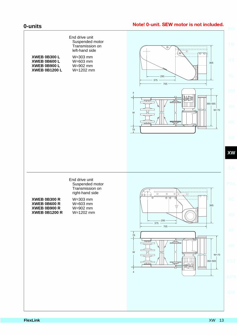
0-units
End drive unitSuspended motorTransmission onleft-hand side
XWEB 0B300 LXWEB 0B600 LXWEB 0B900 LXWEB 0B1200 L
W=303 mmW=603 mmW=902 mmW=1202 mm
End drive unitSuspended motorTransmission onright-hand side
XWEB 0B300 RXWEB 0B600 RXWEB 0B900 RXWEB 0B1200 R
W=303 mmW=603 mmW=902 mmW=1202 mm
76
365
W
4
705
W+70
360-565
375
295
76
365
W
4
705
W+70
360-565
375295
PO
TR
XS
XL
XM
XH
XK
XB
XW
CA
PAL
XC
XD
XF
XR
FST
APX
IDX
FlexLink XW 13
Double drive units
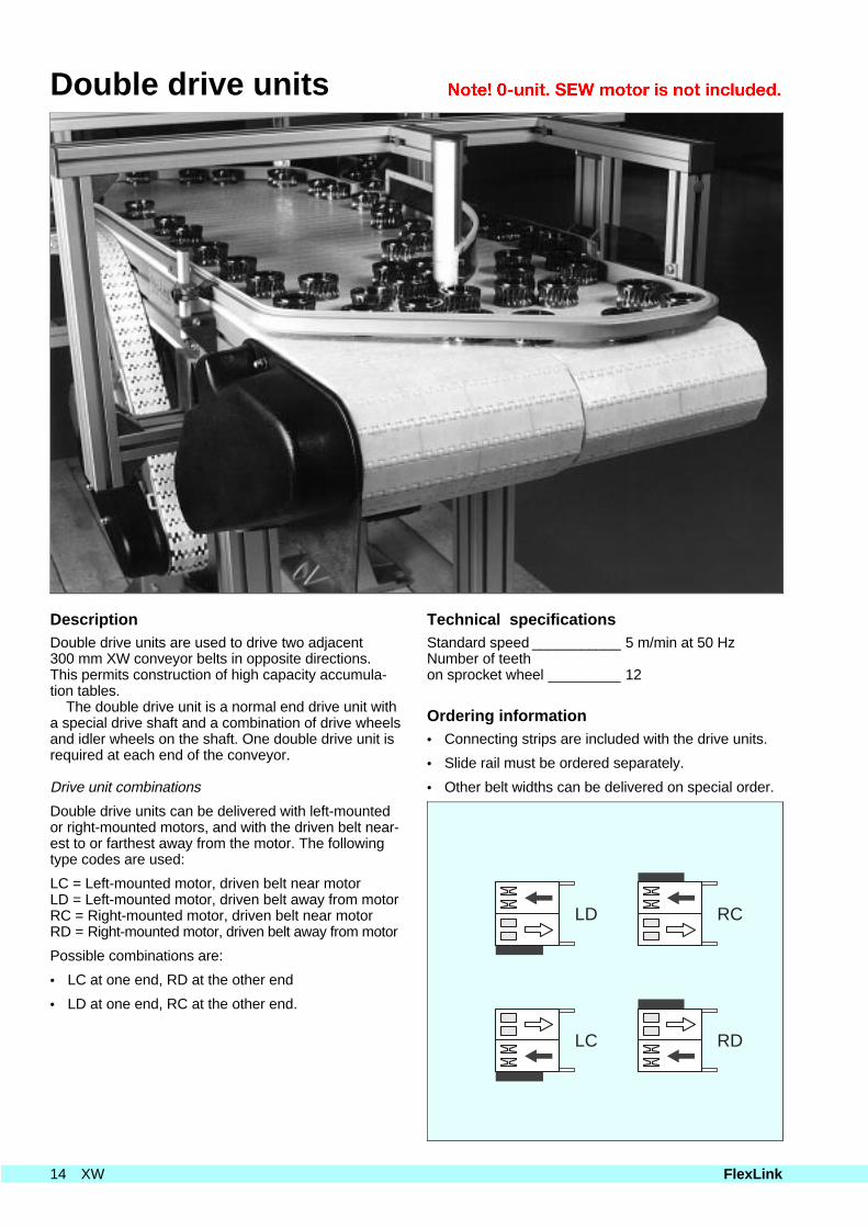
DescriptionDouble drive units are used to drive two adjacent300 mm XW conveyor belts in opposite directions.This permits construction of high capacity accumula-tion tables.
The double drive unit is a normal end drive unit witha special drive shaft and a combination of drive wheelsand idler wheels on the shaft. One double drive unit isrequired at each end of the conveyor.
Drive unit combinations
Double drive units can be delivered with left-mountedor right-mounted motors, and with the driven belt near-est to or farthest away from the motor. The followingtype codes are used:
LC = Left-mounted motor, driven belt near motorLD = Left-mounted motor, driven belt away from motorRC = Right-mounted motor, driven belt near motorRD = Right-mounted motor, driven belt away from motor
Possible combinations are:
• LC at one end, RD at the other end
• LD at one end, RC at the other end.
Technical specificationsStandard speed ___________ 5 m/min at 50 HzNumber of teeth on sprocket wheel _________ 12
Ordering information• Connecting strips are included with the drive units.
• Slide rail must be ordered separately.
• Other belt widths can be delivered on special order.
LD
LC
RC
RD
14 XW FlexLink
Double 0-units
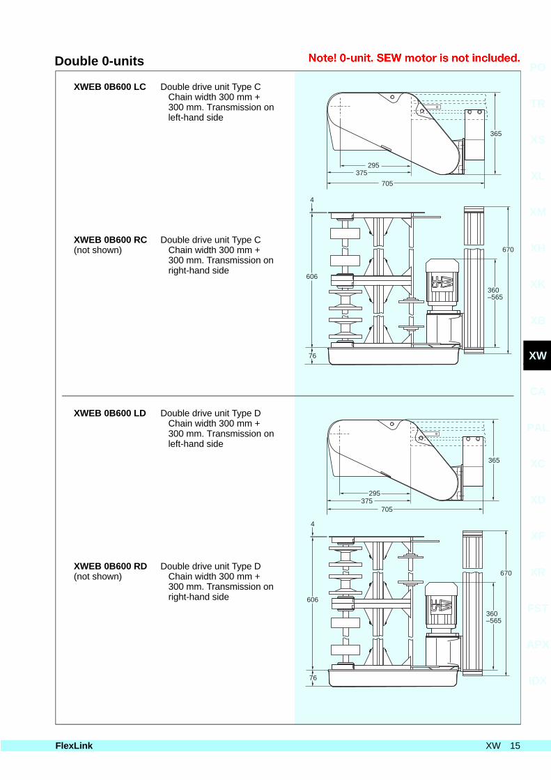
XWEB 0B600 LC Double drive unit Type CChain width 300 mm +300 mm. Transmission onleft-hand side
XWEB 0B600 RC(not shown)
Double drive unit Type CChain width 300 mm +
300 mm. Transmission on right-hand side
XWEB 0B600 LD Double drive unit Type DChain width 300 mm +300 mm. Transmission onleft-hand side
XWEB 0B600 RD(not shown)
Double drive unit Type DChain width 300 mm +
300 mm. Transmission on right-hand side
76
365
606
705
670
360–565
4
375295
76
365
606
705
670
360–565
4
375295
PO
TR
XS
XL
XM
XH
XK
XB
XW
CA
PAL
XC
XD
XF
XR
FST
APX
IDX
FlexLink XW 15
Triple drive units
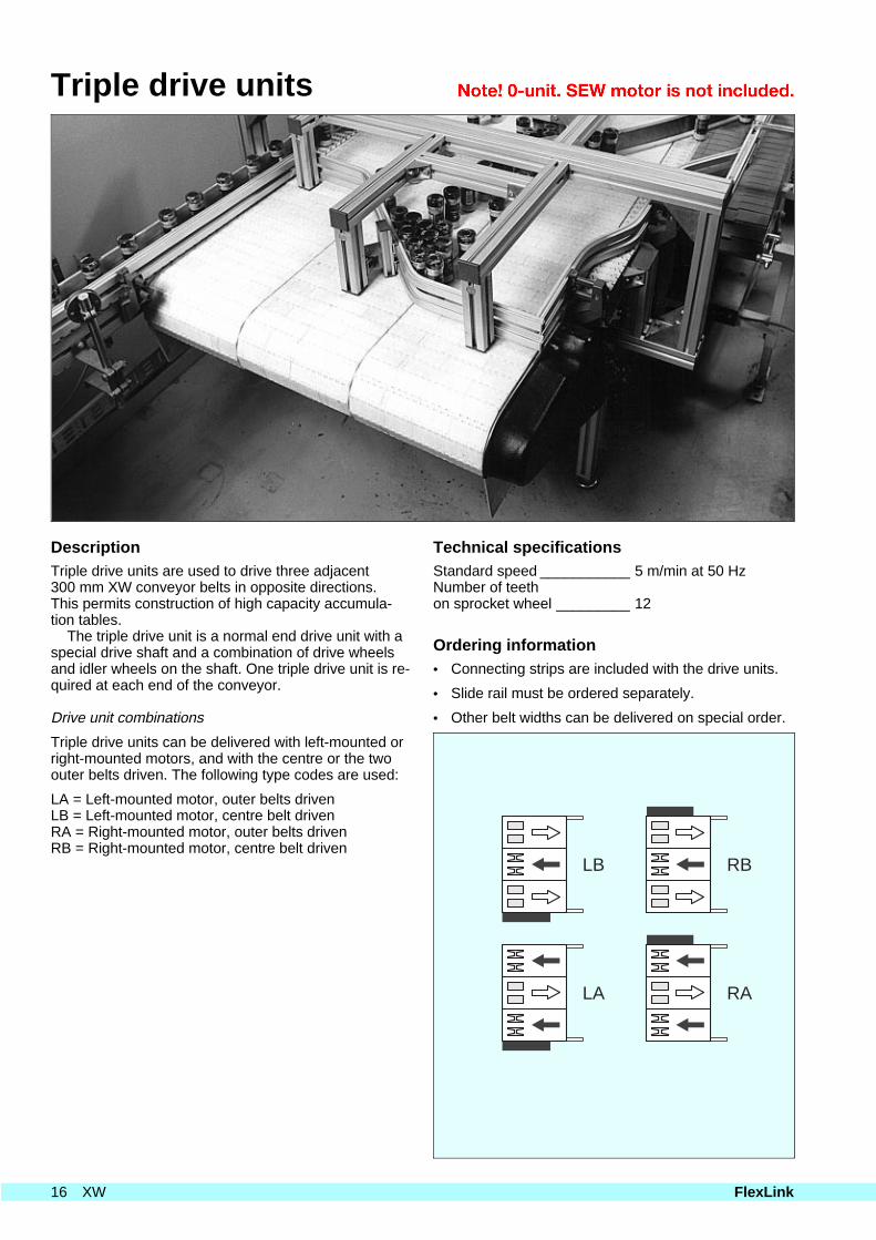
DescriptionTriple drive units are used to drive three adjacent300 mm XW conveyor belts in opposite directions.This permits construction of high capacity accumula-tion tables.
The triple drive unit is a normal end drive unit with aspecial drive shaft and a combination of drive wheelsand idler wheels on the shaft. One triple drive unit is re-quired at each end of the conveyor.
Drive unit combinations
Triple drive units can be delivered with left-mounted orright-mounted motors, and with the centre or the twoouter belts driven. The following type codes are used:
LA = Left-mounted motor, outer belts drivenLB = Left-mounted motor, centre belt drivenRA = Right-mounted motor, outer belts drivenRB = Right-mounted motor, centre belt driven
Technical specificationsStandard speed ___________ 5 m/min at 50 HzNumber of teeth on sprocket wheel _________ 12
Ordering information• Connecting strips are included with the drive units.
• Slide rail must be ordered separately.
• Other belt widths can be delivered on special order.
LB
LA
RB
RA
16 XW FlexLink
Triple drive units
XWEB 0B900 LA Triple drive unit Type AChain width300+300+300 mm. Trans-mission on left-hand side
XWEB 0B900 RA(not shown)
Triple drive unit Type A Chain width 300+300+300 mm. Trans- mission on right-hand side
XWEB 0B900 LB Triple drive unit Type BChain width300+300+300 mm. Trans-mission on left-hand side
XWEB 0B900 RB(not shown)
Triple drive unit Type B Chain width 300+300+300 mm. Trans- mission on right-hand side
76
365
907
705
970
360–565
4
375295
76
365
907
705
970
360–565
4
375295
PO
TR
XS
XL
XM
XH
XK
XB
XW
CA
PAL
XC
XD
XF
XR
FST
APX
IDX
FlexLink XW 17
Idler end units
DescriptionThe idler end unit is used to guide the chain from thereturn side of the conveyor up to the top side with aminimum of friction. The chain is guided by two ormore idler wheels on a common, rotating shaft sup-ported by SKF ball bearings.
Idler units for 900 mm and 1200 mm conveyors in-clude an additional shaft support at the centre.
Number of idler wheels vs. conveyor width
Width 300 mm 600 mm 900 mm 1200 mm
Idler wheels 2 4 6 8
Shaft supports 1 1
Material specificationsSee Technical reference.
Ordering information• Connecting strips are included with the idler end
units.
• Slide rail must be ordered separately.
18 XW FlexLink
Idler end units
Idler end unitXWEJ 300 BXWEJ 600 BXWEJ 900 BXWEJ 1200 B
W=303 mmW=603 mmW=902 mmW=1202 mm
PO
TR
XS
XL
XM
XH
XK
XB
XW
CA
PAL
XC
XD
XF
XR
FST
APX
IDX
FlexLink XW 19
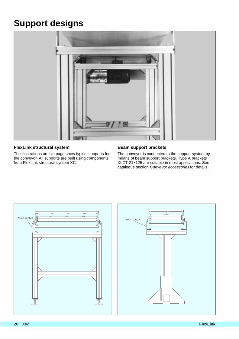
Support designs
FlexLink structural systemThe illustrations on this page show typical supports forthe conveyor. All supports are built using componentsfrom FlexLink structural system XC.
Beam support bracketsThe conveyor is connected to the support system bymeans of beam support brackets. Type A bracketsXLCT 21×125 are suitable in most applications. Seecatalogue section Conveyor accessories for details.