16
GEA Wiegand GmbH Cooling under Vacuum
GEA Wiegand GmbH
Cooling under Vacuum
2
IntroductionTable of Contents
Introduction 2
Comparison between compression cooling plants
and steam jet cooling plants 2
Steam Jet Cooling Plants – Construction Details
and How They Work 3
Advantages of flash cooling plants 3
Vapour compression using jet pumps 4
Flash cooling 4
Steam Jet Cooling Plants – Types 5
Steam jet cooling plants of compact design 5
Steam jet cooling plants of column design 6
Steam jet cooling plants of bridge design 7
Standardised steam jet cooling plants – sizes 8
Installation and Control 10
Possible combinations 10
Installation alternatives 11
Control of steam jet cooling plants 12
Heat Recovery Plants 14
Criteria for the Design
of Steam Jet Cooling Plants 15
Cooling is an expensive process. Ongoing increases inenergy costs demand alternatives to traditional systems(mechanical compressors). More and more, flash coolingplants offer an environmentally friendly and economicalsolution. GEA Wiegand has more than fifty years of experience inthe design and construction of flash cooling plants.
GEA Wiegand reference plants:
wateraqueous nitric acid/phosphoric acidaqueous plaster suspensioncalcium milkbarium hydroxide solutionsvarious waste watersfruit juicemilkglue
The steam jet cooling plants may have a capacity betweenapproximately 10 and 20 000 kilowatts. As an example,water may be cooled down to a temperature of approxi-mately 5 °C.
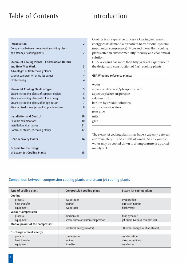
Comparison between compression cooling plants and steam jet cooling plants
Type of cooling plant Compression cooling plant Steam jet cooling plant
Coolingprocess evaporation evaporationheat transfer indirect direct or indirectequipment evaporator flash vessel
Vapour Compressionprocess mechanical fluid dynamicequipment screw, turbo or piston compressor jet pump (vapour compressor)
Motive power of the compressor electrical energy (motor) thermal energy (motive steam)
Discharge of heat energyprocess condensation condensationheat transfer indirect direct or indirectequipment liquefier condenser
3
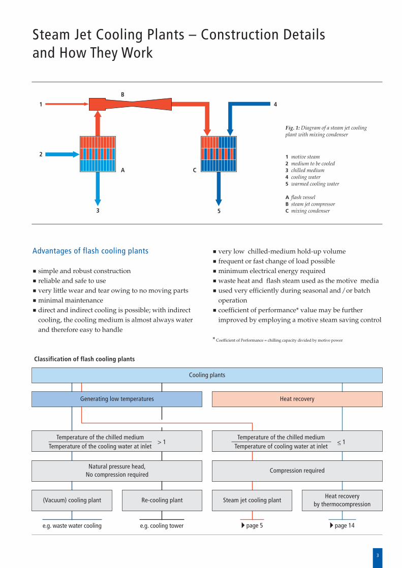
1 motive steam2 medium to be cooled3 chilled medium4 cooling water5 warmed cooling water
A flash vesselB steam jet compressorC mixing condenser
Fig. 1: Diagram of a steam jet coolingplant with mixing condenser
Advantages of flash cooling plants
simple and robust constructionreliable and safe to usevery little wear and tear owing to no moving parts minimal maintenancedirect and indirect cooling is possible; with indirectcooling, the cooling medium is almost always waterand therefore easy to handle
very low chilled-medium hold-up volumefrequent or fast change of load possibleminimum electrical energy required waste heat and flash steam used as the motive media used very efficiently during seasonal and/or batchoperation coefficient of performance* value may be furtherimproved by employing a motive steam saving control
* Coefficient of Performance = chilling capacity divided by motive power
Classification of flash cooling plants
Cooling plants
Generating low temperatures Heat recovery
Temperature of the chilled mediumTemperature of the cooling water at inlet
> 1Temperature of the chilled medium
Temperature of cooling water at inlet<_ 1
Natural pressure head, No compression required
(Vacuum) cooling plant Re-cooling plant Steam jet cooling plantHeat recovery
by thermocompression
Compression required
e.g. waste water cooling e.g. cooling tower � page 5 � page 14
Steam Jet Cooling Plants – Construction Details and How They Work
1
2
3
4
5
A C
B
4
Steam Jet Cooling Plants – Construction Details and How They Work
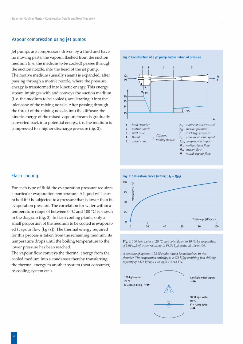
Vapour compression using jet pumps
Jet pumps are compressors driven by a fluid and haveno moving parts: the vapour, flashed from the suctionmedium (i. e. the medium to be cooled) passes throughthe suction nozzle, into the head of the jet pump. The motive medium (usually steam) is expanded, afterpassing through a motive nozzle, where the pressureenergy is transformed into kinetic energy. This energystream impinges with and conveys the suction medium(i. e. the medium to be cooled), accelerating it into theinlet cone of the mixing nozzle. After passing throughthe throat of the mixing nozzle, into the diffusor, thekinetic energy of the mixed vapour stream is graduallyconverted back into potential energy, i. e. the medium iscompressed to a higher discharge pressure (fig. 2).
p1 motive steam pressurep0 suction pressurep discharge pressureps pressure at sonic speedΔpv compression impactM· 1 motive steam flowM· 0 suction flowM· mixed-vapour flow
1 head chamber2 motive nozzle3 inlet cone4 throat5 outlet cone � diffusor,
mixing nozzle
Fig. 2: Construction of a jet pump and variation of pressure
Fig. 4: 100 kg/s water at 20 °C are cooled down to 10 °C by evaporationof 1.66 kg/s of water resulting in 98.34 kg/s water at the outlet.
A pressure of approx. 1.23 kPa (abs.) must be maintained in this chamber. The evaporation enthalpy is 2 478 kJ/kg resulting in a chillingcapacity of 2478 kJ/kg x 1.66 kg/s = 4 113 kW.
Flash cooling
For each type of fluid the evaporation pressure requiresa particular evaporation temperature. A liquid will startto boil if it is subjected to a pressure that is lower than itsevaporation pressure. The correlation for water within atemperature range of between 0 °C and 100 °C is shownin the diagram (fig. 3). In flash cooling plants, only asmall proportion of the medium to be cooled is evaporat -ed (vapour flow [kg/s]). The thermal energy requiredfor this process is taken from the remaining medium: itstemperature drops until the boiling temperature to thelower pressure has been reached. The vapour flow conveys the thermal energy from thecooled medium into a condenser thereby transferringthe thermal energy to another system (heat consumer, re-cooling system etc.).
Fig. 3: Saturation curve (water) : ts = f(ps)
5
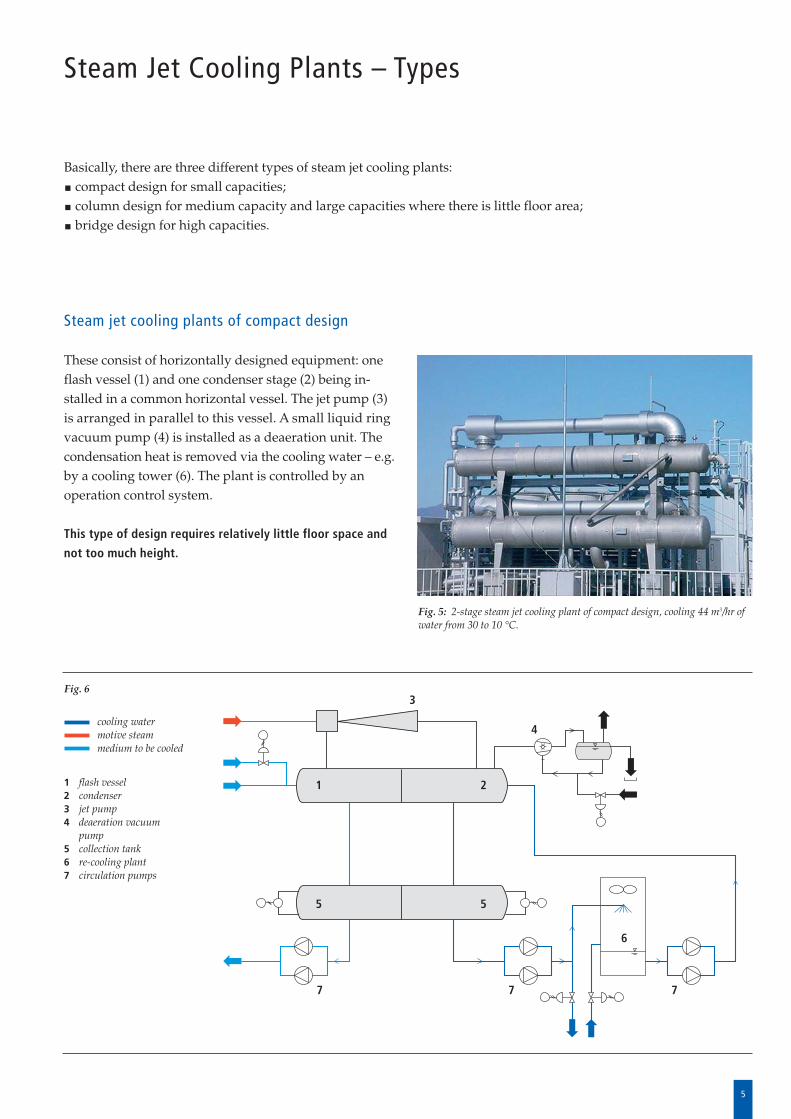
Steam jet cooling plants of compact design
These consist of horizontally designed equipment: oneflash vessel (1) and one condenser stage (2) being in -stalled in a common horizontal vessel. The jet pump (3)is arranged in parallel to this vessel. A small liquid ringvacuum pump (4) is installed as a deaeration unit. Thecondensation heat is removed via the cooling water – e.g.by a cooling tower (6). The plant is controlled by anoperation control system.
This type of design requires relatively little floor space and
not too much height.
cooling watermotive steammedium to be cooled
1 flash vessel2 condenser3 jet pump4 deaeration vacuum
pump5 collection tank6 re-cooling plant7 circulation pumps
Fig. 5: 2-stage steam jet cooling plant of compact design, cooling 44 m3/hr ofwater from 30 to 10 °C.
21
55
7 7 7
3
4
6
Steam Jet Cooling Plants – Types
Basically, there are three different types of steam jet cooling plants: compact design for small capacities;column design for medium capacity and large capacities where there is little floor area;bridge design for high capacities.
Fig. 6
6
Steam Jet Cooling Plants – Types
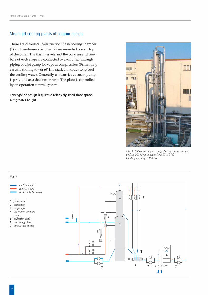
Steam jet cooling plants of column design
These are of vertical construction: flash cooling chamber(1) and condenser chamber (2) are mounted one on topof the other. The flash vessels and the condenser cham-bers of each stage are connected to each other throughpiping or a jet pump for vapour compression (3). In manycases, a cooling tower (6) is installed in order to re-coolthe cooling water. Generally, a steam jet vacuum pumpis provided as a deaeration unit. The plant is controlledby an operation control system.
This type of design requires a relatively small floor space,
but greater height.
cooling watermotive steammedium to be cooled
1 flash vessel2 condenser3 jet pumps4 deaeration vacuum
pump5 collection tank6 re-cooling plant7 circulation pumps
Fig. 7: 2-stage steam jet cooling plant of column design,cooling 200 m3/hr of water from 10 to 5 °C.Chilling capacity: 1163 kW
1
3
3
4
5
6
7 7 7
2
Fig. 8
7
Steam Jet Cooling Plants – Types
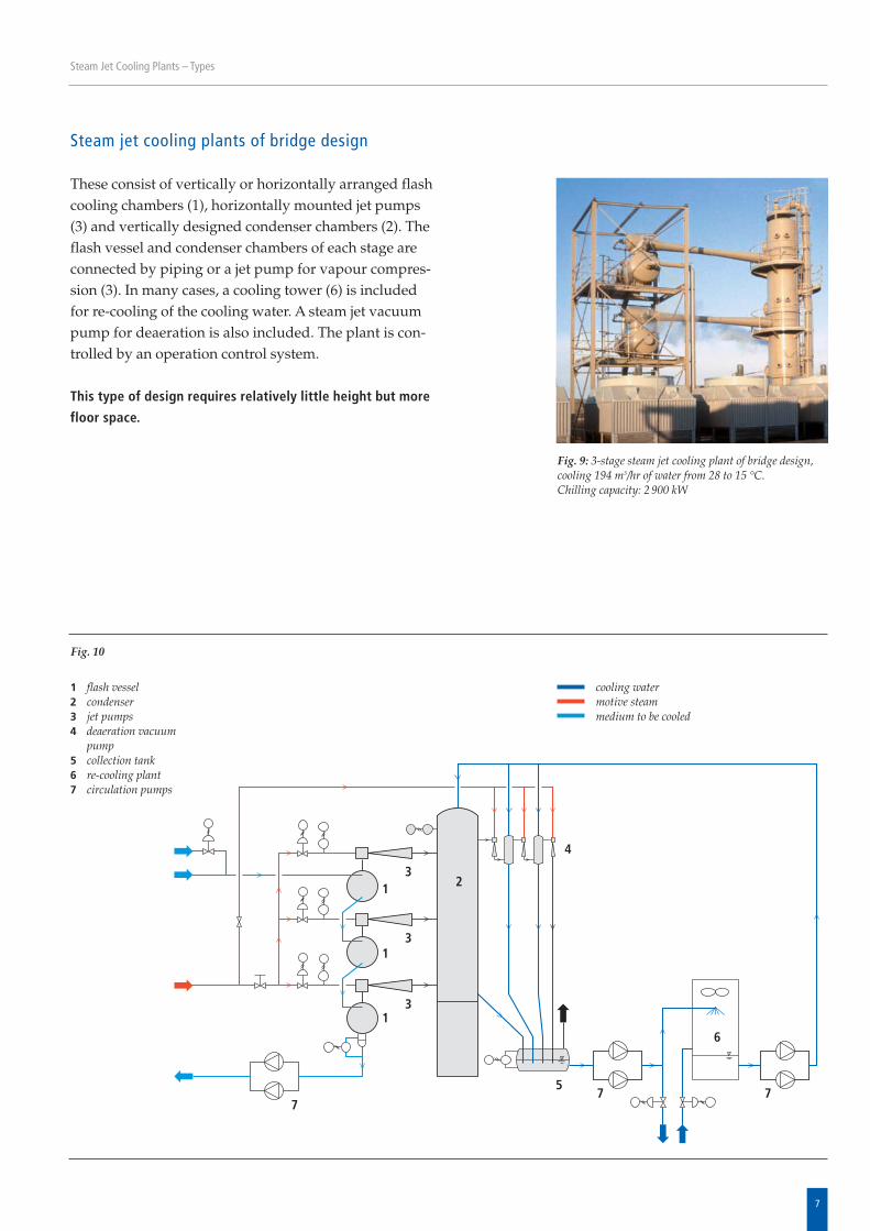
Steam jet cooling plants of bridge design
These consist of vertically or horizontally arranged flashcooling chambers (1), horizontally mounted jet pumps(3) and vertically designed condenser chambers (2). Theflash vessel and condenser chambers of each stage areconnected by piping or a jet pump for vapour compres-sion (3). In many cases, a cooling tower (6) is includedfor re-cooling of the cooling water. A steam jet vacuumpump for deaeration is also included. The plant is con -trolled by an operation control system.
This type of design requires relatively little height but more
floor space.
cooling watermotive steammedium to be cooled
1 flash vessel2 condenser3 jet pumps4 deaeration vacuum
pump5 collection tank6 re-cooling plant7 circulation pumps
Fig. 9: 3-stage steam jet cooling plant of bridge design,cooling 194 m3/hr of water from 28 to 15 °C.Chilling capacity: 2 900 kW
7
1
1
1
23
3
3
4
5
6
7 7
Fig. 10
8
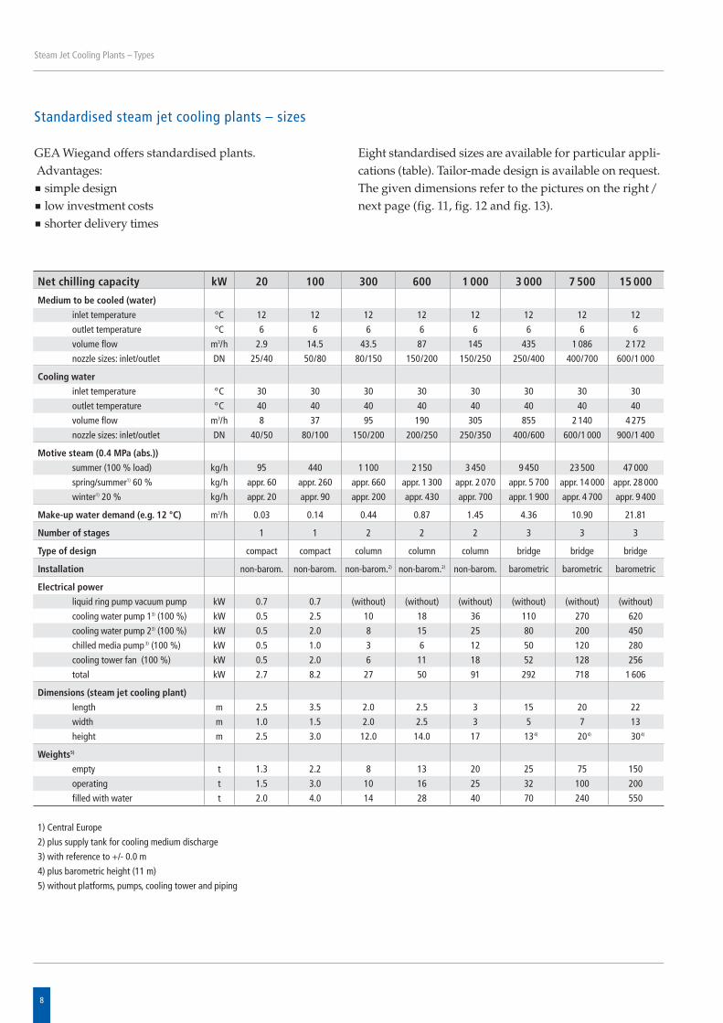
GEA Wiegand offers standardised plants.Advantages:
simple designlow investment costsshorter delivery times
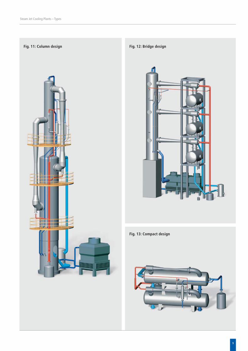
Eight standardised sizes are available for particular appli-cations (table). Tailor-made design is available on request.The given dimensions refer to the pictures on the right/next page (fig. 11, fig. 12 and fig. 13).
Steam Jet Cooling Plants – Types
Standardised steam jet cooling plants – sizes
Net chilling capacity kW 20 100 300 600 1 000 3 000 7 500 15 000
Medium to be cooled (water)
inlet temperature °C 12 12 12 12 12 12 12 12
outlet temperature °C 6 6 6 6 6 6 6 6
volume flow m3/h 2.9 14.5 43.5 87 145 435 1 086 2 172
nozzle sizes: inlet/outlet DN 25/40 50/80 80/150 150/200 150/250 250/400 400/700 600/1 000
Cooling water
inlet temperature °C 30 30 30 30 30 30 30 30
outlet temperature °C 40 40 40 40 40 40 40 40
volume flow m3/h 8 37 95 190 305 855 2 140 4 275
nozzle sizes: inlet/outlet DN 40/50 80/100 150/200 200/250 250/350 400/600 600/1 000 900/1 400
Motive steam (0.4 MPa (abs.))
summer (100 % load) kg/h 95 440 1 100 2 150 3 450 9 450 23 500 47 000
spring/summer1) 60 % kg/h appr. 60 appr. 260 appr. 660 appr. 1 300 appr. 2 070 appr. 5 700 appr. 14 000 appr. 28 000
winter1) 20 % kg/h appr. 20 appr. 90 appr. 200 appr. 430 appr. 700 appr. 1 900 appr. 4 700 appr. 9 400
Make-up water demand (e.g. 12 °C) m3/h 0.03 0.14 0.44 0.87 1.45 4.36 10.90 21.81
Number of stages 1 1 2 2 2 3 3 3
Type of design compact compact column column column bridge bridge bridge
Installation non-barom. non-barom. non-barom.2) non-barom.2) non-barom. barometric barometric barometric
Electrical power
liquid ring pump vacuum pump kW 0.7 0.7 (without) (without) (without) (without) (without) (without)
cooling water pump 13) (100 %) kW 0.5 2.5 10 18 36 110 270 620
cooling water pump 23) (100 %) kW 0.5 2.0 8 15 25 80 200 450
chilled media pump 3) (100 %) kW 0.5 1.0 3 6 12 50 120 280
cooling tower fan (100 %) kW 0.5 2.0 6 11 18 52 128 256
total kW 2.7 8.2 27 50 91 292 718 1 606
Dimensions (steam jet cooling plant)
length m 2.5 3.5 2.0 2.5 3 15 20 22
width m 1.0 1.5 2.0 2.5 3 5 7 13
height m 2.5 3.0 12.0 14.0 17 134) 204) 304)
Weights5)
empty t 1.3 2.2 8 13 20 25 75 150
operating t 1.5 3.0 10 16 25 32 100 200
filled with water t 2.0 4.0 14 28 40 70 240 550
1) Central Europe
2) plus supply tank for cooling medium discharge
3) with reference to +/- 0.0 m
4) plus barometric height (11 m)
5) without platforms, pumps, cooling tower and piping
9
Steam Jet Cooling Plants – Types
Fig. 11: Column design
Fig. 13: Compact design
Fig. 12: Bridge design
10
Installation and Control
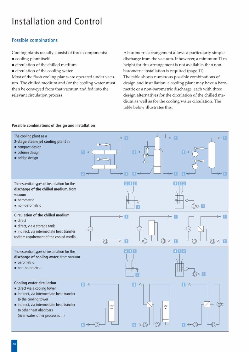
Possible combinations
A barometric arrangement allows a particularly simpledischarge from the vacuum. If however, a minimum 11 mheight for this arrangement is not available, than non-barometric installation is required (page 11).The table shows numerous possible combinations ofdesign and installation: a cooling plant may have a baro-metric or a non-barometric discharge, each with threedesign alternatives for the circulation of the chilled me -di um as well as for the cooling water circulation. Thetable below illustrates this.
Cooling plants usually consist of three components:cooling plant itselfcirculation of the chilled mediumcirculation of the cooling water
Most of the flash cooling plants are operated under vacu -um. The chilled medium and/or the cooling water mustthen be conveyed from that vacuum and fed into therelevant circulation process.
The cooling plant as a 2-stage steam jet cooling plant in
compact design column designbridge design
The essential types of installation for thedischarge of the chilled medium, fromvacuum
barometricnon-barometric
Circulation of the chilled mediumdirectdirect, via a storage tankindirect, via intermediate heat transfer
to/from requirement of the cooled-media.
The essential types of installation for thedischarge of cooling water, from vacuum
barometricnon-barometric
Cooling water circulationdirect via a cooling towerindirect, via intermediate heat transfer to the cooling towerindirect, via intermediate heat transfer to other heat absorbers(river water, other processes ...)
Possible combinations of design and installation
1 1
5
4
5
4
5
4
1
3
1
3
1
2 2 2 2 2 2
3
3
4 4 4
6
5
6
5
6
5
6
3
4 4 4
6
2
1
22
11
Installation and Control
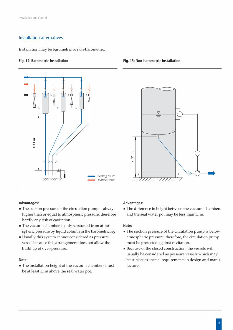
Installation alternatives
Advantages:
The suction pressure of the circulation pump is alwayshigher than or equal to atmospheric pressure, thereforehardly any risk of cavitation.The vacuum chamber is only separated from atmo -spheric pressure by liquid column in the barometric leg.Usually this system cannot considered as pressurevessel because this arrangement does not allow thebuild up of over-pressure.
Note:
The installation height of the vacuum chambers mustbe at least 11 m above the seal water pot.
Fig. 14: Barometric installation
Advantages:
The difference in height between the vacuum chambersand the seal water pot may be less than 11 m.
Note:
The suction pressure of the circulation pump is belowatmospheric pressure, therefore, the circulation pumpmust be protected against cavitation. Because of the closed construction, the vessels willusually be considered as pressure vessels which maybe subject to special requirements in design and manu-facture.
Fig. 15: Non-barometric Installation
Installation may be barometric or non-barometric:
cooling watermotive steam
>_ 11
m
< 1
1 m
12
Installation and Control
Control of steam jet cooling plants
Steam jet cooling plants are controlled
in order to match the chilling capacity to the relevantdemand and/or to reduce operating costs.
Capacity control
The capacity of a steam jet cooling plant can be alteredby turning on/off the motive steam valves of the individ -ual jet pumps. Assuming a constant flow of the mediumto be cooled, the chilling capacity can be controlled inaccordance with the temperature of the chilled mediumat the outlet of the steam jet cooling plant. This can bemade either manually or by automatic control.
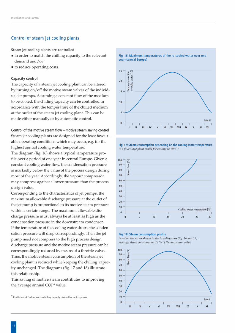
Control of the motive steam flow – motive steam saving control
Steam jet cooling plants are designed for the least favour -able operating conditions which may occur, e.g. for thehighest annual cooling water temperature. The diagram (fig. 16) shows a typical temperature pro -file over a period of one year in central Europe. Given aconstant cooling water flow, the condensation pressureis markedly below the value of the process design duringmost of the year. Accordingly, the vapour compressormay compress against a lower pressure than the processdesign value. Corresponding to the characteristics of jet pumps, themax imum allowable discharge pressure at the outlet ofthe jet pump is proportional to its motive steam pressurewithin a certain range. The maximum allowable dis -charge pressure must always be at least as high as thecondensation pressure in the downstream condenser. If the temperature of the cooling water drops, the con den -sation pressure will drop correspondingly. Then the jetpump need not compress to the high process designdischarge pressure and the motive steam pressure can becorrespondingly reduced by means of a throttle valve.Thus, the motive steam consumption of the steam jetcooling plant is reduced while keeping the chilling capac -ity unchanged. The diagrams (fig. 17 and 18) illustratethis relationship. This saving of motive steam contributes to improvingthe average annual COP* value.
* Coefficient of Performance = chilling capacity divided by motive power
Fig. 16: Maximum temperatures of the re-cooled water over oneyear (central Europe)
Fig. 17: Steam consumption depending on the cooling water temperature in a four stage plant (valid for cooling to 10 ºC)
Fig. 18: Steam consumption profilebased on the ratios shown in the two diagrams (fig. 16 and 17).Average steam consumption 72 % of the maximum value
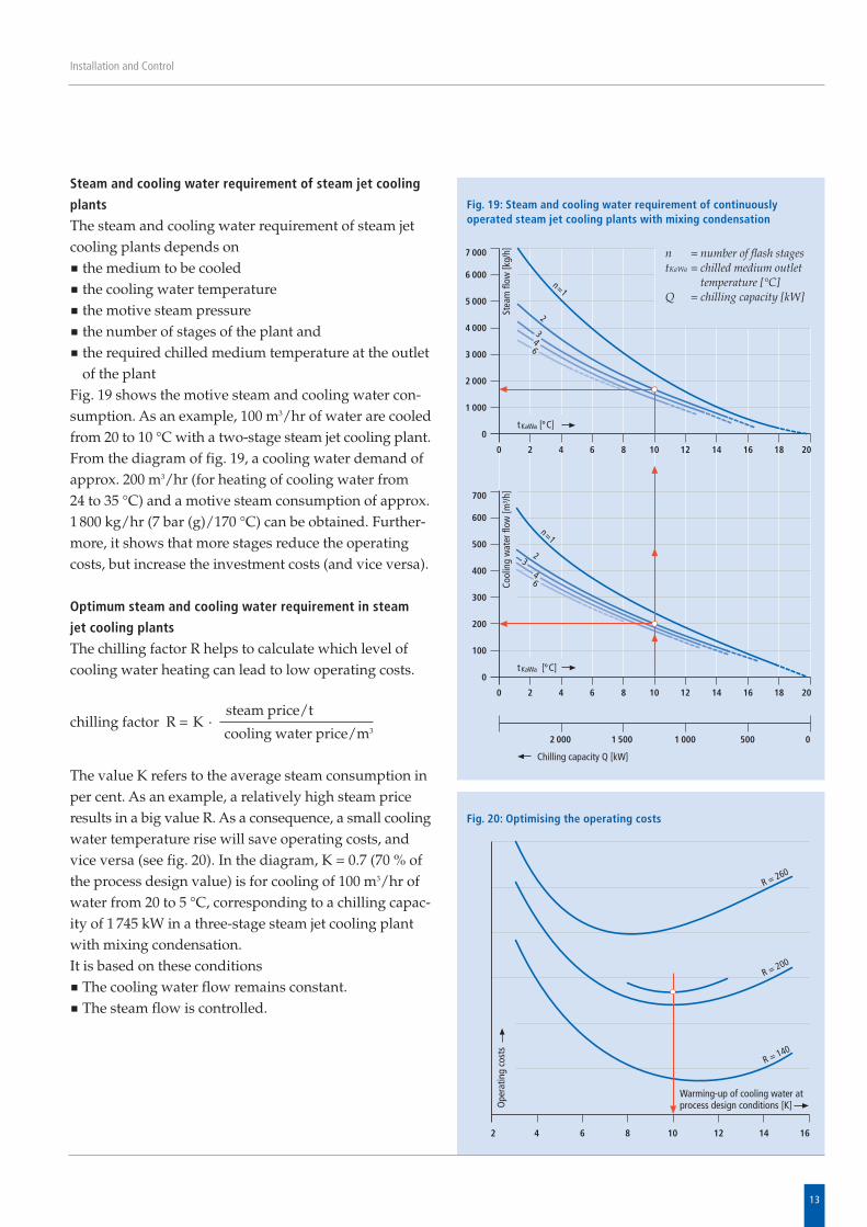
Steam and cooling water requirement of steam jet cooling
plants
The steam and cooling water requirement of steam jetcooling plants depends on
the medium to be cooledthe cooling water temperaturethe motive steam pressurethe number of stages of the plant andthe required chilled medium temperature at the outletof the plant
Fig. 19 shows the motive steam and cooling water con -sumption. As an example, 100 m3/hr of water are cooledfrom 20 to 10 °C with a two-stage steam jet cooling plant.From the diagram of fig. 19, a cooling water de mand ofapprox. 200 m3/hr (for heating of cooling water from 24 to 35 °C) and a motive steam consumption of approx.1 800 kg/hr (7 bar (g)/170 °C) can be obtained. Further-more, it shows that more stages reduce the operatingcosts, but increase the investment costs (and vice versa).
Optimum steam and cooling water requirement in steam
jet cooling plants
The chilling factor R helps to calculate which level ofcooling water heating can lead to low operating costs.
The value K refers to the average steam consumption inper cent. As an example, a relatively high steam priceresults in a big value R. As a consequence, a small coolingwater temperature rise will save operating costs, andvice versa (see fig. 20). In the diagram, K = 0.7 (70 % ofthe process de sign value) is for cooling of 100 m3/hr ofwater from 20 to 5 °C, corresponding to a chilling capac -ity of 1 745 kW in a three-stage steam jet cooling plantwith mixing condensation. It is based on these conditions
The cooling water flow remains constant.The steam flow is controlled.
13
Installation and Control
Fig. 19: Steam and cooling water requirement of continuouslyoperated steam jet cooling plants with mixing condensation
n = number of flash stagestKaWa = chilled medium outlet
temperature [°C]Q = chilling capacity [kW]
chilling factor R = K · steam price/t
cooling water price/m3
Fig. 20: Optimising the operating costs
14
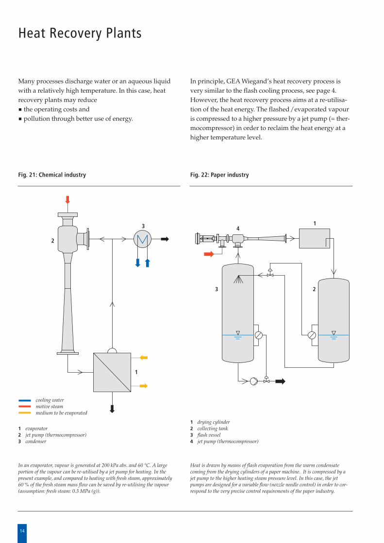
Heat Recovery Plants
Many processes discharge water or an aqueous liquidwith a relatively high temperature. In this case, heatrecovery plants may reduce
the operating costs andpollution through better use of energy.
In principle, GEA Wiegand’s heat recovery process isvery similar to the flash cooling process, see page 4.However, the heat recovery process aims at a re-utilisa-tion of the heat energy. The flashed/evaporated vapouris compressed to a higher pressure by a jet pump (= ther -mocompressor) in order to reclaim the heat energy at ahigher temperature level.
Heat is drawn by means of flash evaporation from the warm condensatecoming from the drying cylinders of a paper machine. It is compressed by ajet pump to the higher heating steam pressure level. In this case, the jet pumps are designed for a variable flow (nozzle needle control) in order to cor -respond to the very precise control requirements of the paper industry.
Fig. 22: Paper industry
In an evaporator, vapour is generated at 200 kPa abs. and 60 °C. A largeportion of the vapour can be re-utilised by a jet pump for heating. In thepresent example, and compared to heating with fresh steam, approximately 60 % of the fresh steam mass flow can be saved by re-utilising the vapour(assumption: fresh steam: 0.3 MPa (g)).
Fig. 21: Chemical industry
cooling watermotive steammedium to be evaporated
1 drying cylinder2 collecting tank3 flash vessel4 jet pump (thermocompressor)
1 evaporator2 jet pump (thermocompressor)3 condenser
2
1
14
23
3
15
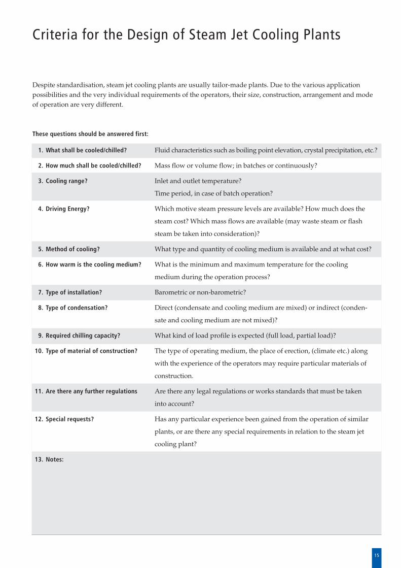
Criteria for the Design of Steam Jet Cooling Plants
Despite standardisation, steam jet cooling plants are usually tailor-made plants. Due to the various applicationpossibilities and the very individual requirements of the operators, their size, construction, arrangement and modeof operation are very different.
These questions should be answered first:
1. What shall be cooled/chilled? Fluid characteristics such as boiling point elevation, crystal precipitation, etc.?
2. How much shall be cooled/chilled? Mass flow or volume flow; in batches or continuously?
3. Cooling range? Inlet and outlet temperature?
Time period, in case of batch operation?
4. Driving Energy? Which motive steam pressure levels are available? How much does the
steam cost? Which mass flows are available (may waste steam or flash
steam be taken into consideration)?
5. Method of cooling? What type and quantity of cooling medium is available and at what cost?
6. How warm is the cooling medium? What is the minimum and maximum temperature for the cooling
medium during the operation process?
7. Type of installation? Barometric or non-barometric?
8. Type of condensation? Direct (condensate and cooling medium are mixed) or indirect (conden -
sate and cooling medium are not mixed)?
9. Required chilling capacity? What kind of load profile is expected (full load, partial load)?
10. Type of material of construction? The type of operating medium, the place of erection, (climate etc.) along
with the experience of the operators may require particular materials of
construction.
11. Are there any further regulations Are there any legal regulations or works standards that must be taken
into account?
12. Special requests? Has any particular experience been gained from the operation of similar
plants, or are there any special requirements in relation to the steam jet
cooling plant?
13. Notes:
P106
E 02
2009
/ H
inke
l & J
ungh
ans,
Wer
beag
entu
r, K
A
Process Engineering
GEA Wiegand GmbHEinsteinstrasse 9-15, 76275 Ettlingen, Germany Tel. +49 7243 705-0, Fax +49 7243 705-330 E-Mail: [email protected], Internet: www.gea-wiegand.com
Overview on our Range of ProductsEvaporation plantsto concentrate any type of fluid food, process water, organic and inorganic solutions and industrial waste water; with additional equip-ment for heating, cooling, degassing, crystallization and rectification.
Membrane filtration – GEA Filtrationto concentrate and process fluid food, process water and industrial waste water, to separate contaminations in order to improve quality and recover valuable substances.
Distillation / rectification plantsto separate multi-component mixtures, to recover organic solvents; to clean, recover and dehydrate bio-alcohol of different qualities.
Alcohol production linesfor potable alcohol and dehydrated alcohol of absolute purity; integrated stillage processing systems.
Condensation plantswith surface or mixing condensers, to condense vapour and steam/gas mixtures under vacuum.
Vacuum/steam jet cooling plantsto produce cold water, cool liquids, even of aggressive and abrasive nature.
Jet pumpsto convey and mix gases, liquids, and granular solids; for direct heating of liquids; as heat pumps; and in special design for the most diverse fields of application.
Steam jet vacuum pumpsalso product vapour driven; also in combination with mechanical vacuum pumps (hybrid systems); extensive application in the chemical, pharmaceutical and food industries, in oil refineries and for steel degassing.
Heat recovery plantsto utilize residual heat from exhaust gases, steam/air mixtures, condensate and product.
Vacuum degassing plantsto remove dissolved gases from water and other liquids.
Heating and cooling plantsmobile and stationary plants for the operation of hot water heated reactors, contact driers.
Gas scubbersto clean and dedust exhaust air, separate aerosols, cool and condition gases, condensate vapours and absorb gaseous pollutants.
Project studies, engineering for our plants.


