COOPERATIVE FABRICATION METHODOLOGY FOR EMBEDDING WIREON CURVED SURFACES C.Y. Kim, A. Cuaron, M.A. Perez, D. Espalin, E. MacDonald, and R.B. Wicker *W.M.Keck Center for 3D Innovation, The University of Texas at El Paso, El Paso, TX79968 Abstract In conventional additive manufacturing (AM), an object is fabricated by depositing material in a layer by layer fashion. Typically, this process is retained so that deposition can occur on flat surfaces and motion can be constrained to requiring only three degrees of freedom (DOF) in a Cartesian coordinate system. When incorporating wire in three-dimensional (3D) objects, there is sometimes a need for placement along curved surfaces on which positions are defined not only by 3D Cartesian coordinates but also angular ones. Therefore, a minimum of two additional DOFs are required allowing movement to be generated at the build platform as well as of the extrusion head. This paper addresses a method for trajectory planning of both systems, that is, the extrusion head and the movable build platform, allowing for cooperative and harmonic motion between the two. Introduction Material extrusion additive manufacturing (AM), more commonly referred to as Fused Deposition Modeling (FDM) extrudes a thermoplastic through a small diameter tip and is placed on a planar build surface to build an object one layer at a time. This manufacturing technology is rapidly growing in various applications [1][2]. To increase the diversity of applications this technology can be used in, the researchers have explored the possibility of multi-material material fabrication and integration of embedded wire. Previous research developed a multi- functional, multi-material system with the capability to fabricate with four different materials [3]. Successive research manufactured a CubeSat subsystem containing an FDM-build substrate, commercial off-the-shelf electronic components, and conductive ink traces [4]. This same work demonstrated an alternative to direct write of conductive inks for creating traces, which involved the ultrasonic embedding of solid copper wire. Another method for creating traces is metal fused deposition modeling, and although this method shows enhanced conductivity, challenges still exist in depositing metals on 3D surfaces. This obstacles must be resolved as the ability to embed metal on 3Dsurfaces of FDM-fabricated parts is essential in advancing research in the 3D printed electronics and mechanics field. Therefore flexible tooling FDM technologies, which can deposit a material along various angular positions, were introduced. Song et al. attempted to make a 6 DOF FDM system using a Stewart platform integrated into the tool head, allowing for flexible deposition of material [5]. Lee et al. used a 5 axis desktop CNC, converted into an FDM machine, in which the tool head was able to move linearly in the z and x directions, while rotating along the y-axis and the base moved in the y direction while rotating along the x-axis [6]. To optimize embedding metal onto the surface of an object, the tool head must be perpendicular to the surface of the model base. For that to be maintained, an actuator is required to change the orientation of each tool. Although conventional 3D printers have 3 DOFs equipped with an 185
Transcript
COOPERATIVE FABRICATION METHODOLOGY FOR EMBEDDING WIREON CURVED SURFACES
C.Y. Kim, A. Cuaron, M.A. Perez, D. Espalin, E. MacDonald, and R.B. Wicker
*W.M.Keck Center for 3D Innovation, The University of Texas at El Paso, El Paso, TX79968
Abstract
In conventional additive manufacturing (AM), an object is fabricated by depositing material in a layer by layer fashion. Typically, this process is retained so that deposition can occur on flat surfaces and motion can be constrained to requiring only three degrees of freedom (DOF) in a Cartesian coordinate system. When incorporating wire in three-dimensional (3D) objects, there is sometimes a need for placement along curved surfaces on which positions are defined not only by 3D Cartesian coordinates but also angular ones. Therefore, a minimum of two additional DOFs are required allowing movement to be generated at the build platform as well as of the extrusion head. This paper addresses a method for trajectory planning of both systems, that is, the extrusion head and the movable build platform, allowing for cooperative and harmonic motion between the two.
Introduction Material extrusion additive manufacturing (AM), more commonly referred to as Fused Deposition Modeling (FDM) extrudes a thermoplastic through a small diameter tip and is placed on a planar build surface to build an object one layer at a time. This manufacturing technology is rapidly growing in various applications [1][2]. To increase the diversity of applications this technology can be used in, the researchers have explored the possibility of multi-material material fabrication and integration of embedded wire. Previous research developed a multi-functional, multi-material system with the capability to fabricate with four different materials [3]. Successive research manufactured a CubeSat subsystem containing an FDM-build substrate, commercial off-the-shelf electronic components, and conductive ink traces [4]. This same work demonstrated an alternative to direct write of conductive inks for creating traces, which involved the ultrasonic embedding of solid copper wire. Another method for creating traces is metal fused deposition modeling, and although this method shows enhanced conductivity, challenges still exist in depositing metals on 3D surfaces. This obstacles must be resolved as the ability to embed metal on 3Dsurfaces of FDM-fabricated parts is essential in advancing research in the 3D printed electronics and mechanics field. Therefore flexible tooling FDM technologies, which can deposit a material along various angular positions, were introduced. Song et al. attempted to make a 6 DOF FDM system using a Stewart platform integrated into the tool head, allowing for flexible deposition of material [5]. Lee et al. used a 5 axis desktop CNC, converted into an FDM machine, in which the tool head was able to move linearly in the z and x directions, while rotating along the y-axis and the base moved in the y direction while rotating along the x-axis [6]. To optimize embedding metal onto the surface of an object, the tool head must be perpendicular to the surface of the model base. For that to be maintained, an actuator is required to change the orientation of each tool. Although conventional 3D printers have 3 DOFs equipped with an
185
dlb7274
Typewritten Text
REVIEWED
actuator, this is not enough to maintain the tool perpendicular. Therefore, to embed on a curved surface, a minimum of 2 additional DOFs are required. In this paper, it is suggested that 2 DOF actuators will be added to the build platform. This is a change that can easily be integrated into any conventional FDM system without much system change. In order to deposit the material, the tool head and the build platform must have cooperative control. Also, two trajectories need to be planned, one for the tool head and the other for the build platform. This paper addresses the methodology for trajectory planning to deposit any material on a curved surface with synchronization of both the tool head and the build platform. To verify the proposed method, the methodology was applied when embedding copper wire on an FDM-fabricated part resembling section of a duct or pipeline.
Trajectory Planning This paper suggests a method for harmonic motion trajectory planning for use with an FDM extrusion head and moving build platform. The procedure, based on robot kinematics, is as follows: 1) Calculating the tangent vector of the curved surface in an object’s local coordinate system 2) Finding forward kinematics from the local coordinate 3) Finding forward kinematics from the tool coordinate to the build platform 4) Calculating joint parameters using inverse kinematics and the step 2 transformation to make the surface parallel with the FDM tool head 5) Calculating inverse kinematics and the step 3 transformation to follow the change in target position from Step 4 Deriving the tangent vector on the curved surface The first step in the process, is finding the required rotation angle to allow the tool head approach a build surface in a perpendicular fashion. Any point on the surface of a solid object in ordinary 3D Euclidean space R3, can be generalized by a parametric surface.
(1)
where, is the position vector for any point on the surface. ip is the codirectional vector with basis and its norm is mapped by the bounded surface parameter . Therefore, all positions on the curve are described by parametric surface S . As a 3D model’s surface is already known, based on the CAD created in Cartesian coordinates, this paper uses x, y and z as the basis of a coordinate system. Also, it is able to define surface S as the height of position x, y.
3
1
( , )
( , )
ii
i i
P p
p m u v
P S u v
P
i ,u v
186
(2) Fig (1) shows an arbitrary curved surface in space. Subscript , , , indicate the fields of the movable stage, wire embedding tool, object being built and the local coordinates, respectively. On the surface, two isoperimetric curves were made parallel with each axis: and
. An origin of local coordinates was set at the intersection point of the curves and the axis was set along the tangent of the y
m constant isoperimetric curve. The was set in the same
fashion at the constant. Finally, the axes of the local coordinate frame can be obtained by partial derivative.
(3)
By neglecting the higher order terms, the first order approximation can be used to obtain the slope angles of tangent vector about and .
(4)
( , )z S x y
S t m L
mX
mY LX
LY
mx
( , ) ( , ), , L L
L L LL L
X YS x y S x yX Y Z n
x y X Y
LX LY
2
( , ) ( , )arctan ( , ) ( , )( )
ii
i
S x x y S x yif S x y x S x y x
x
Fig1. Parametric surface and coordinates
XmYm
Zm
XLYL
ZL
Zs
Ys
Xs
lm
Zt
Xt
Yt
lt
x,yc
xc,y
187
(5)
After all, all points on the curved surface can be expressed by position and surface vectors, which can be shown as slope angles. Kinematic Modeling The end-effector coordinates of a Multi-DOF system, which consists of a number of actuators, varies depending on the movement of each actuator. Therefore, one must find the kinematics from the base to the end-effector, based on whole displacement of the actuator in the joints. This paper uses the Denavit-Hartenberg (D-H) convention to solve the kinematic problem in the spatial kinematic chain, such as in the articulated robot [7]. In the D-H representation, each link in the serial chain, shown in Fig (2), is described by a coordinate transformation from the previous coordinate system, forming a homogeneous transformation, D-H matrix, which is a product of four basic transformations.
(6)
The final forward kinematics can be obtained by multiplying each transformation matrix consecutively. Conventional AM systems typically consist of just three prismatic joints to move with three DOFs in a Cartesian coordinate system. Therefore, a submatrix, top left, was simplified to include constant terms in each joint coordinate transformation. This paper adopted revolute joints in the build platform to rotate an object as it is being built. The rotational transformation is shown in the kinematics between the object and build platform. Trajectory Planning According to forward kinematics, the position and orientation of the end-effector in the initial frame are given by
(7)
where, is homogeneous transformation, is D-H matrix and is the actuator variable of the
th joint. Therefore, can represent the desired position and orientation of the end-effector, which will embed the wire on a surface. Next, one must find the values for the joint variables
1, , nq q so that 01( , , )n nT q q H . This inverse kinematics problem is complex and becomes
more difficult with increasing number of joints and complexity of joint composition. However, it is simple to solve the reverse kinematics problem because the rotational term in the transformation becomes a symmetric matrix. The joint variable of AM system will automatically follow the position of the target. If there is no redundancy in DOF and each joint is orthogonal
2
( , ) ( , )arctan ( , ) ( , )( )
ii
i
S x y y S x yif S x y y S x y y
y
, , , ,
cos sin cos sin sin cos
sin cos cos cos sin sin
0 sin cos
0 0 0 1
i z i z di x ai x i
i i i i i i
i i i i i i i
i i i
A Rot Trans Trans Rot
i a
a
d
3 3
01 1( ) ( )n n nH T A q A q
H iA iq
i H
188
on the moving platform, the variable will represent the normal vector of target also. If some redundancy in DOFs and a complex geometry exists, it can solved by jacobian pseudo-inverse[8].
Application
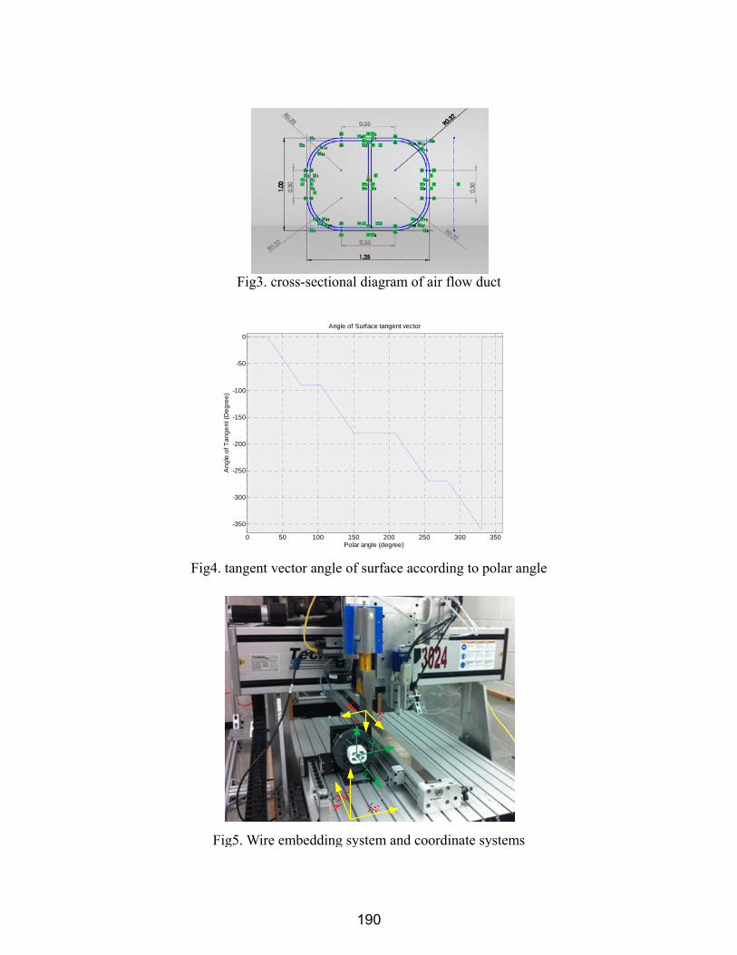
For verification of the proposed trajectory planning method, this chapter utilized the method for embedding copper wire along a curved surface. Surface Analysis Fig (3) shows a cross-sectional diagram of the duct in which a copper wire was embedded. It is of interest to embed copper wires on ducts, pipelines, and other parts to manage the electrostatic charge that can accumulate on nonconductive thermoplastic parts. For example, through the process of selective chemical adsorption, electrostatic charge can accumulate on fuel-carrying plastic pipelines that present ignition hazards due to electrostatic brush discharges and spark discharges when the pipes interact with connecting manifolds or valve bodies [9]. Static electricity can also accumulate on nonconductive plastics used as transfer containers in powder processes which can discharge and cause explosions [10]. As such, a path for dissipating electrostatic charges to earth is required in these types of parts. The wire embedding process demonstrated in this work can ultimately produce a network of conductive paths to mitigate charge accumulation that may lead to an incendive discharge. The surrounding surface of the duct is a composite shape with curves and lines. Because the cross-sectional shape is constant along the center axis, like a rod, the normal vector of the surface is just dependent of the polar angle of the center. Fig (4) shows the angle of tangential vector according to the polar angle. To embed wire around the duct, the tangent angle of each polar position must be horizontal, or perpendicular to the surface, by rotating on a center axis.
Fig2. D-H frame assignment
189
Fig5. Wire embedding system and coordinate systems
Fig4. tangent vector angle of surface according to polar angle
0 50 100 150 200 250 300 350
-350
-300
-250
-200
-150
-100
-50
0
Polar angle (degree)
An
gle
of T
an
ge
nt (
De
gre
e)
Angle of Surface tangent vector
Fig3. cross-sectional diagram of air flow duct
190
System Kinematics
Fig (5) shows the wire embedding system and several coordinate systems. denotes the coordinate of the tool base and and represent the tool end-effector and movable state, respectively. The ultrasonic horn attached to the tool head of the CNC router is able to move in accordance with a 3DOF Cartesian coordinate system, just like a conventional FDM system. When the ultrasonic horn is running, copper wire is supplied through a machined hole, on the side of the horn, and fed through the tip where the copper wire is embedded through ultrasonic welding. A rotary stage was installed on the base platform of the CNC router and designed to rotate the workpiece during a build. Table (1) shows DH-parameters of a 3 DOF CNC router based on the coordinate frame shown in Fig (6). Because of Cartesian characteristics, each joint variable of the CNC router is separated, non-interactive and simply derived as Eq (8).
Table 1. DH- parameter of CNC router
link d a α θ
(8)
1 d1 0* π/2 π
2 d2 0* -π/2 π/2
i** 0 0 -π/2 -π/2
3 d3 0* 0 -π/2
*. it can be set as 0 because of zero setting function of CNC router. **. i denotes an intermedium link.
Fig 6. coordinate frame of CNC router
ot
t s
2
1
3
1 0 0
0 1 0
0 0 1
0 0 0 1
i
i
d
dT
d
191
Inverse Kinematics Two inverse kinematics must be solved so that two moving systems can be driven together harmoniously. Each point of the designated tool path, which draws a shape on the surface,becomes a target point to solve the inverse kinematics. It is recommended that the system with more movement constraints be selected as the base and its inverse kinematics be solved first. In the practice system, the rotary table just had a rotational DOF and was unable to complete translations. If an object has a non-uniform radius shape, the rotation of the object will cause the trajectory point to shift. Therefore, spatial movement,occurring from rotating the workpiece and varying its radius, should be covered by 3 DOF tool. As has been mentioned in the surface analysis section, the rotary stage has to rotate the part to maintain the tangent of the surface horizontal. Therefore, the required angle, solution of inverse kinematic of rotary stage, is opposite-signed to that of the angle of the surface tangent vector. The motion system used in conventional AM is a 3 DOF gantry type Cartesian movement, which is called PPP (prismatic- prismatic- prismatic) type robot and its joint value is uniquely determineddirectly from inverse kinematics. Trajectory planning After solving inverse kinematics, each point of embedding path results in several trajectories, which are thedisplacement and angular position of each joint. Fig (7) shows the resulting trajectories of each joint according to time. The top graphdisplays angular trajectory of the rotary stage on which the part being built is held. This is flipped from the shape shown in Fig(4).The middle and bottom graphs show trajectories of X axis and Z axis joints of tools, respectively. X axis movement is simply a repeatedforward and backward movement, but Z axis movement indicates high changes in specific points.
Fig7. Trajectories of X,Z axis joint and rotary table
0 10 20 30 40 50 60 70 80 90 1000
100
200
300
Time (sec)
Ro
tatio
n (
de
gre
e)
0 10 20 30 40 50 60 70 80 90 100-20
-10
0
10
20
Time (sec)
X-a
xis
Join
t (m
m)
0 10 20 30 40 50 60 70 80 90 10024
26
28
30
32
34
Time (sec)
Z-a
xis
Join
t (m
m)
192
Fig (8) shows the simulation results, which plotted consecutive figures at 8-second intervals. The red circle is the tool’s end position (indicated by an arrow). Simulation test results showed that the tool remained on the surface continuously and the tool and part were moving harmoniously.
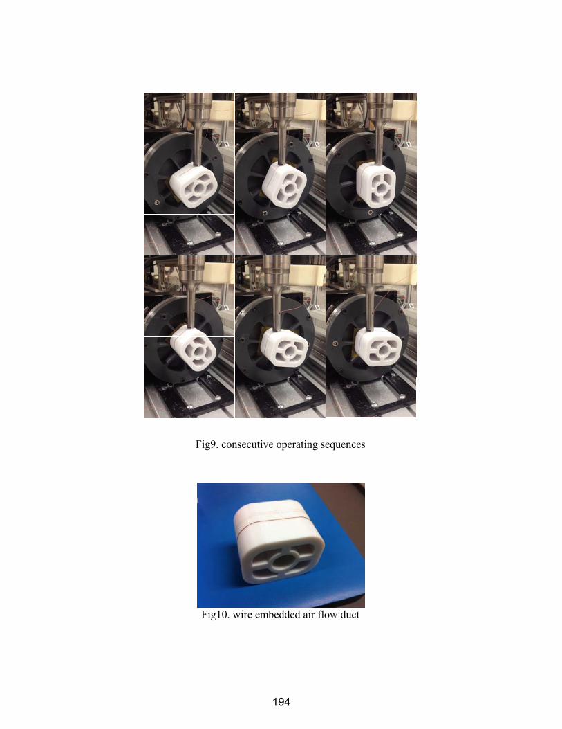
Experimental Test The air flow duct designed in Fig (3) was built by a Stratasys FORTUS 400mc (Eden Prairie, MN) system with polycarbonate. The tool motion of the ultrasonic horn was controlled by a Techno CNC (Ronkonkoma, NY) controller and programmed by SAC script,which is a Techno controller inherent functional library. A rotary stage, movable build platform, was operated bya ATMEGA 128 micro controller. Motion synchronization between the two systems was achieved by handshake signaling trough data ports. ig (9) shows consecutive movements of embedding copper wire around the air flow duct surface and Fig (10) shows a finished result. Althougha small slip occurred at the beginningbecause of insufficient heat by tool, wire was embedded uniformly at most of the points as the tool maintained contact constantly.
Fig8. Simulation test (time step: 8 sec)
193
Fig9. consecutive operating sequences
Fig10. wire embedded air flow duct
194
Conclusion This paper displayed the method for embedding metallic material on thermoplastic structures built by FDM, to achieve multi-material hybrid AM technologies for 3D printed electronics. To dispose metals on a thermoplastic model without slicing a material, it was suggested to embed a wire on the freeform surface by moving the tool head and part simultaneously. Therefore, harmonic and uniform trajectories of each motion systems were required. This paper proposed trajectory planning based on robotics. The proposed methodology was verified by the application of embedding a copper wire on the curved surface of an airflow duct. The result showed that the wire was embedded uniformly at most of the points as the toolheadmaintained constant contact.
Acknowledgment The research presented here was conducted at The University of Texas at El Paso within the W.M. Keck Center for 3D Innovation (Keck Center). Through funding from the State of Texas Emerging Technology Fund, the Keck Center recently expanded to over 13,000 sq. ft., housing state-of-the-art facilities and equipment for additive manufacturing processes, materials, and applications. Specifically, this research was supported by funding from the National Science Foundation Louis Stokes Alliance for Minority Participation program under grant HRD-1139929 as well as the Mr. and Mrs. MacIntosh Murchison Chair I in Engineering Endowment. The authors are grateful to Dan Muse, Fernando Cedillos, Max Winter, Diana Ibarra, Jorge Ramirez, and Alfonso Fernandezfor their participation and contribution.
Reference [1] J. P. Kruth, M. C. Leu, T. Nakagawa, "Progress in Additive Manufacturing and Rapid Prototyping", CIRP Annals - Manufacturing Technology, Vol. 47, Issue. 2. 1998, PP. 525-540. [2] Y. Yan, S. Li, R. Zhang, F. Lin, R. Wu, Q. Lu, Z. Xiong, X. Wang, "Rapid Prototyping and Manufacturing Technology: Principle,Representative Technics, Applications, and Development Trends", Tsinghua Science and Technology, Vol. 14, Issue. S1, 2009, PP. 1-12. [3]D. Espalin, “Development of a multi-material, multi-technology FDM system for process improvement experimentation," M.E thesis, University of Texas at El Paso, El Paso, Texas, 2012. [4] D. Espalin, D. W. Muse, E. MacDonald, R. B. Wicker, "3D Printing multifunctionality: structures with electronics", The International Journal of Advanced Manufacturing Technology. Vol. 72, Issue 5-8, 2014, PP. 963-978. [5]X. Song, Y. Pan, Y. Chen, "Development of a Low-cost Parallel Kinematic Machine for MultidirectionalAdditive Manufacturing",In: Proceedings of the 24th Solid Freeform Fabrication Symposium, Austin, TX, 2003,PP. 297-310. [6] M. Lin, S. Wu, "Modeling and improvement of dynamic contour errors for five-axis machine tools under synchronous measuring paths", International Journal of Machine Tools and Manufacture, Vol. 72, 2013, PP 58-72. [7] M. W. Spong, S. Hutchinson and M. Vidyasagar, Robot Dynamics and Control, John Wiley & Sons, 2008. [8]B. Sicilianno, “Kinematic control of redundant robotmanipulators: A tutorial”, Journal of Intelligent and RoboticSystems, Vol. 3,1990, PP. 201-212. [9]G.L. Hearn,“Electrostatic ignition hazards arising from fuel flow in plastic pipelines”, Journal
195
of Loss Prevention in the Process Industries, 15(2), 2002.PP 105-109. [10]M.Glor,“Ignition hazard due to static electricity in particulate processes”, Powder Technology, 135-136,2003, PP 223-233.