Computer Integrated Construction Research Program Department of Architectural Engineering
The Pennsylvania State University 104 Engineering Unit A
University Park, PA 16802
Abstract
Computer technology has become integrated into every facet of modern day life,providing innovative solutions to a multitude of today’s problems. This is true inthe architectural, engineering, and construction industry, where new technologieshave been changing the way facilities are designed and constructed around theworld. One emerging technology is 4D CAD modeling, where a 3D CAD modelis linked to a construction schedule. This 4D CAD technology has been provento be beneficial in construction applications by several academic and industryprofessionals, showing improved project planning, scheduling, and communicationcapabilities. However, the majority of 4D CAD research has focused on buildingand industrial construction applications, and has not explored highway construc-tion applications. Therefore, this research investigates the applications of 4D CADfor highway construction projects.
The primary research question identified in this thesis is “what are the best applica-tions of 4D CAD for highway construction projects” This question is investigatedusing a case study application of 4D CAD for a highway construction project. The4D model was shown to three groups of highway construction professionals fromdifferent companies. Once each group views the 4D CAD model, their thoughtsand opinions are collected to determine the best applications of 4D CAD for high-way construction projects.
The results of this research show that in the opinions of highway constructionprofessionals, 4D CAD is beneficial for planning, scheduling and communicationapplications in highway construction projects. The best applications of 4D CADfor highway construction are for developing traffic plans and for communicatingthe construction plan to the public. There was a prevailing optimism for 4D CADamong the highway construction professionals, and was seen as “the next logicalstep” in planning, scheduling, and it communication tools for the highway con-struction industry.
I wish to acknowledge and thank those people who contributed to this thesis.I would like to thank Sunil Sinha, H. Randolph Thomas, and John Messner
for serving on my thesis committee. Your patience, guidance, and wisdom haveallowed me to accomplish this graduate research work.
I would like to thank Autodesk for their generous financial and intellectualsupport of this research project. More specifically, I would like to thank DanPhilbrick, Richard Humphrey, Kermit Williams, Mike Rogerson, and everyone fromthe Building Solutions Division (Formally the Infrastructure solutions division)who contributed to this work at some time.
I would like to thank the Shirley Contracting Company, LLC, HRI, Inc, theLane Construction Company, the Clark Construction Group, and Dewberry andDavis, LLC for participating in this research.
I would like to thank The Pennsylvania State University, and in particular theDepartment of Civil and Environmental Engineering, for their continued supportthroughout my undergraduate and graduate work at the University.
I would like to thank my fellow graduate students in the construction engi-neering and management group, the infrastructure asset management group, thecomputing in construction group, and the civil engineering graduate program fortheir insights and opinions throughout my graduate work.
Finally, I would like to thank my Mother and Father for their unwaveringsupport and unconditional love throughout my academic and personal life. It hasbeen a long, bumpy road, so thanks for always sticking behind me through thickand thin. Also, my brother Spencer and my sister Ashley, for being the bestsiblings I could ever imagine. To Jaimye, thank you for all your loving supportover the past three years, and into the future. To all my friends and family, thankyou for being being part of my life.
xi
Chapter 1Introduction
1.1 Introduction
Over the past fifteen years, 4D CAD has gained significant attention in the archi-
tecture, engineering, and construction (AEC) industry. 4D CAD is the result of
linking a 3D CAD model with a construction project schedule in a virtual com-
puter environment (Koo and Fischer, 2000). The idea behind 4D CAD was first
developed in the mid 1980’s, when Bechtel and Hitachi collaborated to develop 4D
Planner software (Cleveland, 1989). Over the years, 4D CAD has developed into
a tool used by planners, designers, and engineers, to analyze and visualize several
phases of a project, from design related decisions, to construction planning, to cost
and resources available (McKinney and Fischer, 1998). 4D CAD has also shown to
improve communication throughout the use of improved visualization of a facility
product and process via shared reference to interactive virtual prototypes (Otto
et al., 2005).
4D CAD technology has risen in response to increased project complexity,
shorter project delivery times, and a general need for better planning techniques.
Typical 2D plans alone do not adequately communicate the 3D geometry of the
structure, and rarely provide the details of the various components indicated in the
design and in the accompanying construction schedule to be used by the construc-
tion personnel (Kunz and Fisher, 2005). Due to the difficulties in understanding
and visualizing the different phases of the construction schedule, unexpected delays
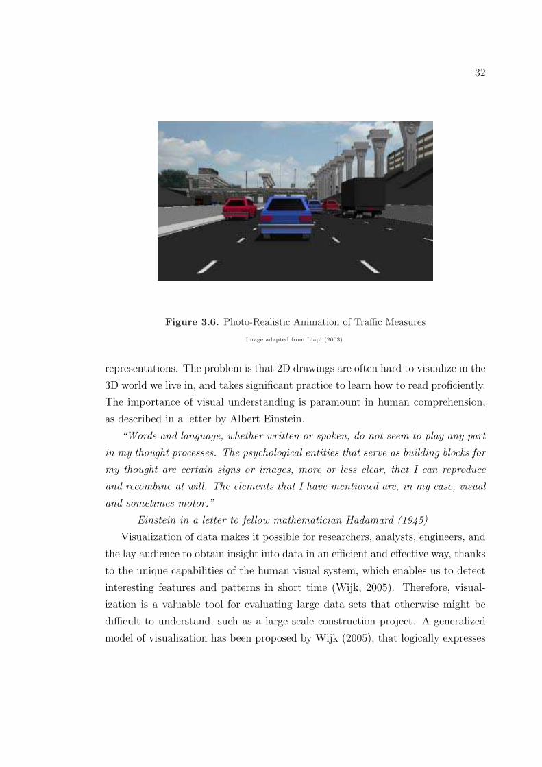
or conflicts that undermine the success of the project often occur (Liapi, 2003).
2
Therefore, 4D CAD has emerged as a powerful tool that can help engineers and
constructors better plan and anticipate construction conflicts before they occur in
the field.
1.1.1 Current 4D CAD Research
Current 4D CAD research has focused almost solely on building construction appli-
cations [Messner and Lynch (2002), Gopinath (2004), Hu et al. (2005)]. Research
programs, such as Penn State’s Computer Integrated Construction program and
Stanford’s CIFE institute have published a plethora of reports and thesis detailing
the benefits of 4D construction simulation in building construction. These pub-
lications have shown benefits ranging from educational construction applications
(Messner et al., 2003) (Messner et al., 2005), to space utilization and site planning
applications (Chau et al., 2004) (Tan et al., 2005). The benefits shown in these
reports have driven the continued interest and popularity of 4D CAD in construc-
tion, and helped create new methods of construction project modeling, such as
building information modeling, or BIM.
The primary focus of the 4D CAD research, as discussed above, has revolved
around building construction. Yet, there has been little investigation into the ben-
efits of 4D CAD for highway construction applications. Transportation projects
often involve complex geometric configurations which render the communication
of project information between interesting parties very difficult and prone to er-
rors (Liapi, 2003). Complex highway interchanges and constantly changing traffic
patterns make highway construction projects increasingly difficult to plan and co-
ordinate before and throughout the construction process. Due to this complexity, it
would be beneficial to apply 4D CAD technologies in highway construction projects
for planning, scheduling and other construction tasks.
This thesis investigates the research question “what are the best use applications
of 4D CAD for highway construction projects and why”. This question is investi-
gated using several research methods, including a case study, surveys, and focus
group discussion, then suggests improvements and lessons learned throughout the
4D CAD development process.
3
1.2 Description of Research Study
This section gives an introduction to the research problem, then describes the
goals, objectives, and other reasons that provided motivation for this research.
1.2.1 Introduction to Research Problem
The applications of 4D CAD for highway construction projects have not been
adequately researched or defined in academic or industry research. 4D CAD has
proven an effective tool for construction planning, scheduling and communication
in building construction, but has not received the same research effort for highway
construction applications. Therefore, this research initiative will investigate and
define what the best use applications of 4D CAD for highway construction projects
are and why. This research will help determine where future research efforts should
be expended, and serve as the groundwork for future 4D CAD research for highway
construction projects.
1.2.2 Goal
The goal of this thesis is to determine what the best use applications of 4D CAD
for highway construction projects are and why. This will help focus future research
and industry efforts while utilizing 4D CAD technology in highway construction
applications. The research also aims to describe and suggest lessons learned from
the 4D CAD development process.
1.2.3 Objectives
1. The primary objective of this research is to investigate what the best
applications of 4D CAD for highway construction projects are
and why.
There has been little investigation into the applications of 4D CAD for high-
way construction projects, with no clear definitions of the benefits and draw-
backs of this technology. This thesis investigates numerous applications of
4D CAD for highway construction, and defines what the most valuable ap-
plications are and why.
4
2. The second objective of this research is to develop a 4D CAD model of
a highway construction project by linking a 3D CAD model with
the project schedule in the Navisworks environment.
This 4D CAD model serves as the primary example used to illustrate the
concepts and ideas expressed in this thesis. It has been presented as the case
study example used to determine both the best use applications and define
the general model development process.
3. The third objective of this research is to document and suggest im-
provements and lessons learned during the 4D CAD development
process.
It is important to document the challenges and pitfalls throughout the 4D
CAD development process so that future researchers can anticipate similar
problems in future research and implementation. It is also valuable to discuss
the solutions to these problems so that they may be improved and solved in
future 4D CAD applications for highway construction.
1.2.4 Research Approach
The research approach that was taken to investigate the applications of 4D CAD for
highway construction used exploratory research methods to investigate this topic.
These methods aimed to collect the opinions and views of highway construction
professionals who work in the highway construction industry on a daily basis, and
offer the best insight and perspective into this topic. Exploratory research methods
are common in social science applications, and were used because 4D CAD for
highway construction is a poorly understood topic that requires better definition
for future research efforts. The exploratory methods aimed to gather qualitative
and quantitative data from three research groups of highway contractors about
their views of 4D CAD for highway construction, then present their ideas in a
logical fashion.
5
1.2.5 Research Steps
The nature of this research requires that exploratory research methods be employed
throughout the investigation of this topic. The exploratory research methods draw
on social science research tools, such as surveys, questionnaires, and open forum
discussion. These methods yield results of both qualitative and quantitative data,
and give valuable insight into previously unexplored topics. The research steps
followed include:
1. Literature Review: A literature review was performed to investigate and
understand topics such as 4D CAD, construction process visualization, high-
way construction techniques, and virtual facility prototyping. The literature
review is presented in Chapter 3.
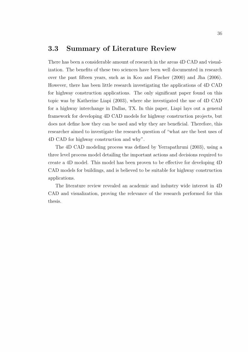
2. Gather Case Study Information: The research case study used a high-
way interchange construction project located in Fairfax County, Virginia,
USA. The project included the removal of a signaled intersection between
Route 28 and McLearen Road, and the construction of a grade separated
interchange. The project was completed in the Summer of 2006, at a cost of
$15 million. A full description of this project is found in Chapter 4.
3. Develop 3D and 4D CAD Models: 3D and 4D CAD models were
developed using the original 2D construction documents prepared for this
interchange project. The 2D contract drawings were modeled in 3D using
Autodesk Civil 3D. The 4D construction simulation was developed using
Navisworks Jetstream V5 with timeliner, by linking the 3D model with the
project schedule.
4. Develop Case Study Evaluation Tools: A number of evaluation tools
were developed to assess the opinions and reactions of the case study project
after viewing the 4D CAD visualization/simulation. These tools employed
social science research methods, such as surveys, open-ended questions, and
focus group discussions. These methods yielded both qualitative and quan-
titative data results used to develop the recommendations presented in this
thesis.
6
5. Perform Survey Questionnaire and Focus Group Discussion: The
survey and focus group discussion were performed at three different contrac-
tor locations in the mid-Atlantic region of the United States. The research
included a total of 17 participants from three separate highway construction
contractors. The data was collected using survey questionnaires, open-ended
questions, focus group discussions, and content analysis. The research was
performed over a three week period in Spring 2007.
6. Review and Analysis of Data: The data collected during the survey
questionnaire and focus group discussion was reviewed and analyzed using
several common research techniques. The results of this research are pre-
sented and discussed in Chapter 5.
7. Discussion and Recommendations for 4D CAD for Highway Con-
struction Projects: A discussion and recommendations are described for
4D CAD for highway construction projects. This expressed improvements
based on the researchers experiences while developing the 3D and 4D CAD
models for the case study project. The lessons learned will also be discussed
in order for future researchers and professionals to avoid the same complica-
tions encountered in this project. These ideas and discussions are presented
in Chapter 6.
8. Document Conclusions from Case Study: The conclusions presented
in this thesis are based on the data collected throughout this research. These
conclusions address the primary research goals and objectives, and are the
primary contribution of this thesis work. These conclusions are presented in
Chapter 7.
1.2.6 Research Contributions
The research contributions from the work performed in this thesis are as follows:
1. A definition and description of the best applications of 4D CAD for highway
construction projects.
7
2. Insights and opinions of highway construction professionals about the appli-
cations of 4D CAD for highway construction.
3. An illustrative case study detailing the 3D and 4D CAD development process.
4. Discussions, suggestions, and improvements of 4D CAD for highway con-
struction projects.
1.3 Relevance and Justification
The effectiveness of 4D CAD for building applications has been well documented in
both academic and industry applications over the past decade. This research has
caused significant shifts in building construction trends, and has helped modernize
a traditionally low-tech industry. The ideas and research presented in this thesis
may help a similar movement in the highway construction industry, and further
implement the benefits of technology into the future. This section presents the
relevance of this research, then gives a few reasons that justify the efforts of this
thesis.
1.3.1 Relevance
This research is relevant to three particular groups of people.
• Highway Construction Contractors: This research is relevant to high-
way contractors because it is defining what the best uses of 4D CAD are
for highway construction projects, and describing why. This is valuable be-
cause in the competitive industry of highway construction, new technology
can separate one contractor from the rest of the crowd, helping them to be
more successful on projects and ultimately winning more business. Some
contractors who are interested in 4D CAD can study this research and un-
derstand what the best application of 4D CAD are for highway construction
and why. This removes the trial and error process that might have been
taken to explore this technology, and helps focus future applications on the
best uses of 4D CAD for highway construction.
8
• Academic and Industry Researchers: This research is relevant for fu-
ture academic and industry researchers because it serves as a foundation for
future research of 4D CAD for highway construction projects. This research
is a base for 4D CAD research for highway construction projects, and defines
specific areas that must be researched in future efforts. This will help fu-
ture researchers focus their research efforts to collect the most relevant and
effective information possible related to this topic.
• Software Developers: This research is relevant to software developers
because it describes numerous software problems that were encountered while
developing a 4D CAD model for a highway construction project. Currently,
there are no adequate softwares that exist on the market to efficiently and
effectively develop 3D CAD models that can be used in 4D CAD applications.
Therefore, a software company can use the information presented in this
thesis as a starting point to create or improve software.
1.3.2 Research Justification
There are numerous justifications that support this research at this point in history.
These are the motivating factors for pursuing this research effort, and writing this
thesis.
1.3.2.1 Software Developments
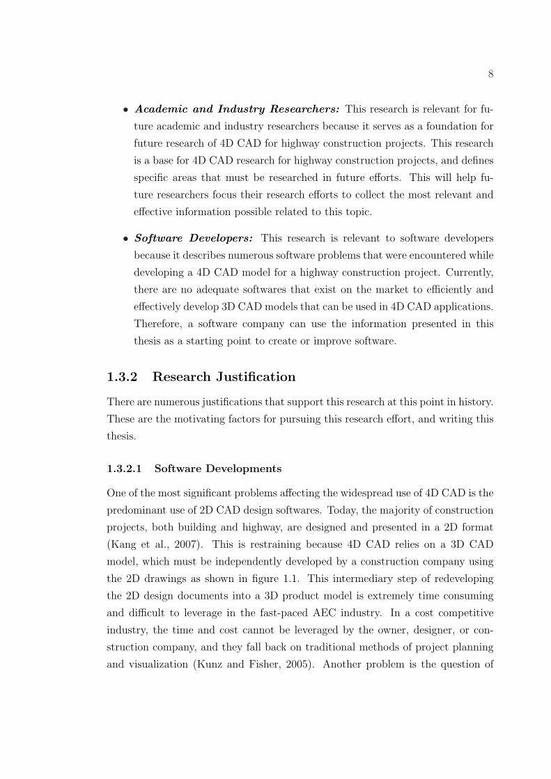
One of the most significant problems affecting the widespread use of 4D CAD is the
predominant use of 2D CAD design softwares. Today, the majority of construction
projects, both building and highway, are designed and presented in a 2D format
(Kang et al., 2007). This is restraining because 4D CAD relies on a 3D CAD
model, which must be independently developed by a construction company using
the 2D drawings as shown in figure 1.1. This intermediary step of redeveloping
the 2D design documents into a 3D product model is extremely time consuming
and difficult to leverage in the fast-paced AEC industry. In a cost competitive
industry, the time and cost cannot be leveraged by the owner, designer, or con-
struction company, and they fall back on traditional methods of project planning
and visualization (Kunz and Fisher, 2005). Another problem is the question of
9
who’s responsibility is it for developing the 3D model. The construction company
believes it is the responsibility of the designer, and the designer believes the op-
posite. This finger-pointing consistently results in a standstill, and no progress is
made (Kunz and Fisher, 2005).
Figure 1.1. Typical 4D CAD Development Process
Image adapted from Messner et al. (2005)
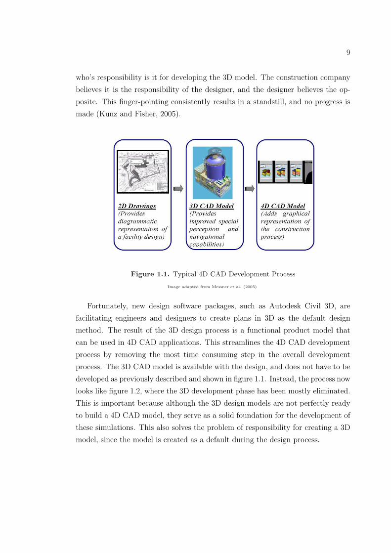
Fortunately, new design software packages, such as Autodesk Civil 3D, are
facilitating engineers and designers to create plans in 3D as the default design
method. The result of the 3D design process is a functional product model that
can be used in 4D CAD applications. This streamlines the 4D CAD development
process by removing the most time consuming step in the overall development
process. The 3D CAD model is available with the design, and does not have to be
developed as previously described and shown in figure 1.1. Instead, the process now
looks like figure 1.2, where the 3D development phase has been mostly eliminated.
This is important because although the 3D design models are not perfectly ready
to build a 4D CAD model, they serve as a solid foundation for the development of
these simulations. This also solves the problem of responsibility for creating a 3D
model, since the model is created as a default during the design process.
10
Streamlined Development Process
Figure 1.2. Streamlined 4D CAD Development Process
Image adapted from Messner et al. (2005)
1.3.2.2 Government Implementation
A second justification for investigating what the best use applications of 4D CAD
are for highway construction projects are that industry implementation may be
streamlined with the help of the US government. If 3D and 4D CAD models are
equally beneficial in the engineering, procurement and construction of highways
as in buildings, the US Federal Highway Administration could enact a similar
mandate to the US General Services Agency. In 2005 the GSA realized the benefits
of building information models (BIM’s), which are object oriented 3D CAD models
that are equivalent to the 3D models generated in Autodesk Civil 3D. The GSA
announced that:
“For all major projects (prospectus-level) receiving design funding in Fiscal Year
2007 and beyond, GSA requires spatial program BIMs be the minimum requirements
for submission to the Office of the Chief Architect for Final Concept approvals by
the PBS Commissioner.”
United State General Services Agency, Matta (2005)
This edict propelled the development of BIM among government designers and
contractors, forcing them to choose between learning and adopting BIM or losing
the largest facility owner in the world as a client. The project logic follows that
11
if similar events were to take place in the Federal Highway Administration, 3D
highway CAD models could see implementation within the near future.
1.3.2.3 Fewer Design and Construction Players
A third justification for investigating what the best applications of 4D CAD are
for highway construction is that implementation may be easier in the highway
construction industry compared with the building construction industry. Building
design and construction requires numerous different design parties, including ar-
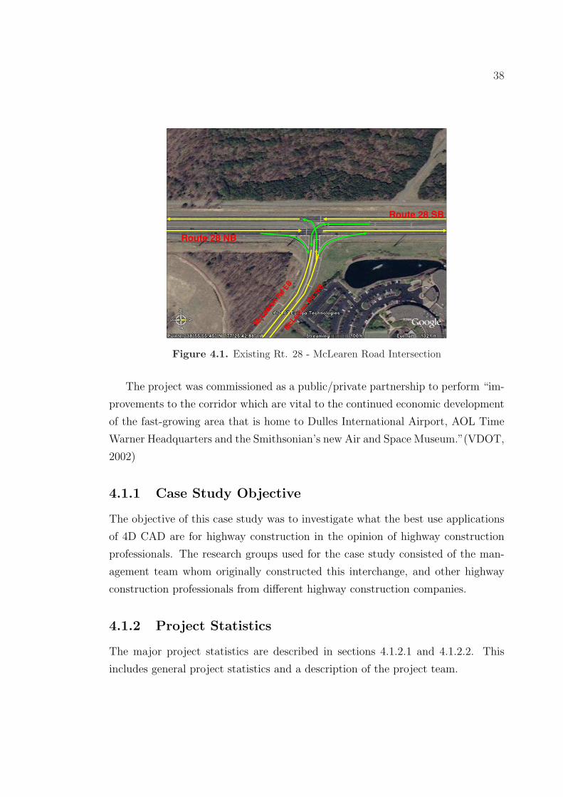
• Location: 38◦55’53.43” N Latitude 77◦25’47.66” W Longitude
Intersection of Route 28 and McLearen Road, Fairfax County, Virginia
• Project Budget: $15 Million
• Funding Source: Private
• Schedule Duration: 450 Days (Summer 2005 - Summer 2006)
• Contract Type: Lump Sum
• Delivery Method: Design-Build
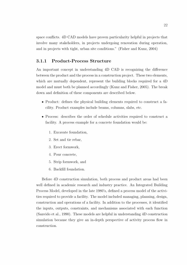
4.1.2.2 Project Team
The project team consisted of the following stakeholders:
• Owner: Virginia Department of Transportation
• Developer: Route 28 Corridor Improvements, LLC
40
• Development Manager: Clark Construction Group Inc.
• Contractor: Shirley Contracting Company, LLC
• Designer: Dewberry and Davis, LLC
4.2 Project Description
The Route 28 - McLearen Road interchange project required the construction of
a high capacity, grade-separated trumpet-style interchange between Route 28 and
McLearen Road in Fairfax County, VA. The project scope included the construction
of four interchange ramps and an overpass bridge carrying traffic between Route
28 and McLearen Road. The new interchange ramps were identified as ramps
A, B, C, and D. Ramp A carries McLearen Road west bound traffic to Rt. 28
north bound. Ramp B carries McLearen Road west bound traffic to Rt. 28 south
bound. Ramp C carries Rt. 28 south bound traffic to McLearen Road east bound.
Ramp D carries Rt. 28 north bound traffic to McLearen Road east bound. The
scope of work also included the construction of a perimeter access road for Dulles
Airport. Since the west portion of the project enters into Dulles Airport property,
an access road must be constructed per FAA requirements to allow vehicle access to
the airport perimeter for security and other maintenance purposes (FAA, 2007).
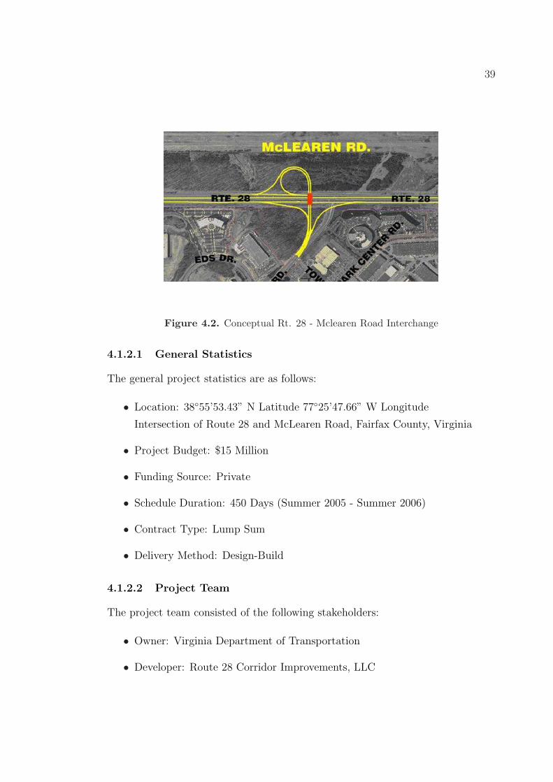
Figure 4.3 shows the western area of the project, including the locations of the
airport access road and ramps B, D, and C.
The project also included the demolition of the existing McLearen Road in-
tersection, then reconstruction of McLearen Road connecting it to the overpass
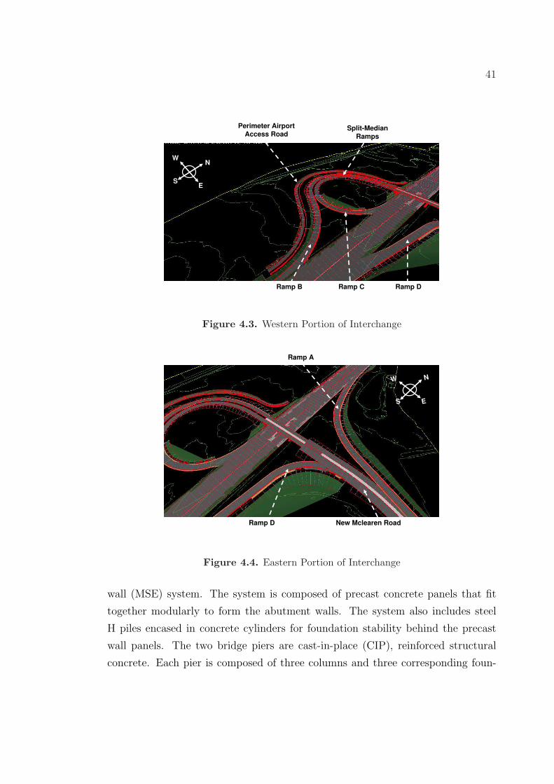
bridge. Figure 4.4 shows the eastern portion of the construction area, including
the new McLearen Road construction and ramp A and D. Figure 4.5 shows the
demolition of existing McLearen Road.
4.2.1 Bridge Description
The overpass bridge is a three span structure carrying traffic between McLearen
Road and Route 28. The primary bridge elements include abutments, piers, foun-
dations, and deck. The bridge abutments employ a mechanically stabilized earth
41
Perimeter Airport
Access Road
Ramp B Ramp C Ramp D
Split-Median
Ramps
NW
ES
Figure 4.3. Western Portion of Interchange
NW
ES
Ramp A
Ramp D New Mclearen Road
Figure 4.4. Eastern Portion of Interchange
wall (MSE) system. The system is composed of precast concrete panels that fit
together modularly to form the abutment walls. The system also includes steel
H piles encased in concrete cylinders for foundation stability behind the precast
wall panels. The two bridge piers are cast-in-place (CIP), reinforced structural
concrete. Each pier is composed of three columns and three corresponding foun-
42
NW
ES
Demolish Old
Mclearen Road
Demolish Old
Mclearen Road
Figure 4.5. Western Portion of Interchange
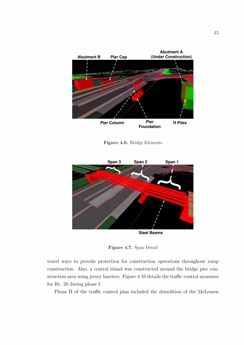
dations. The columns are connected with a precast concrete piercap. Figure 4.6
details a number of the bridge elements.
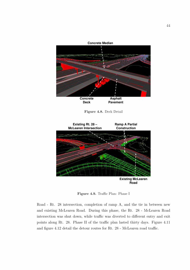
The bridge spans are composed of five steel I beams for each span, as shown
in figure 4.7. The bridge deck and parapet is CIP reinforced concrete, with a
slip-formed concrete median separating the eastbound and westbound lanes. The
surface of the bridge lanes are paved asphalt. Figure 4.8 details bridge deck, asphalt
pavement, and the center median.
4.2.2 Traffic Control Plan
The traffic control plan for the Rt. 28 - McLearen Road interchange project was
divided into two phases. Phase I included the construction of the airport access
road, bridge structure, and ramps B, C, D, and partially ramp A . Since ramp A
crossed the existing McLearen Road, a portion of this ramp had to be postponed
until the road was closed to traffic. Throughout phase I of the traffic plan, the
existing Rt. 28 - McLearen Road signaled interchange remained open to traffic.
Figure 4.9 shows phase I of the traffic plan.
The Rt. 28 traffic controls during phase I closed both the north bound and
south bound shoulders of Rt 28. Jersey barriers were placed at the edges of the
43
Pier Cap
Pier Column PierFoundation
Abutment A (Under Construction)Abutment B
H Piles
Figure 4.6. Bridge Elements
Span 3 Span 2
Steel Beams
Span 1
Figure 4.7. Span Detail
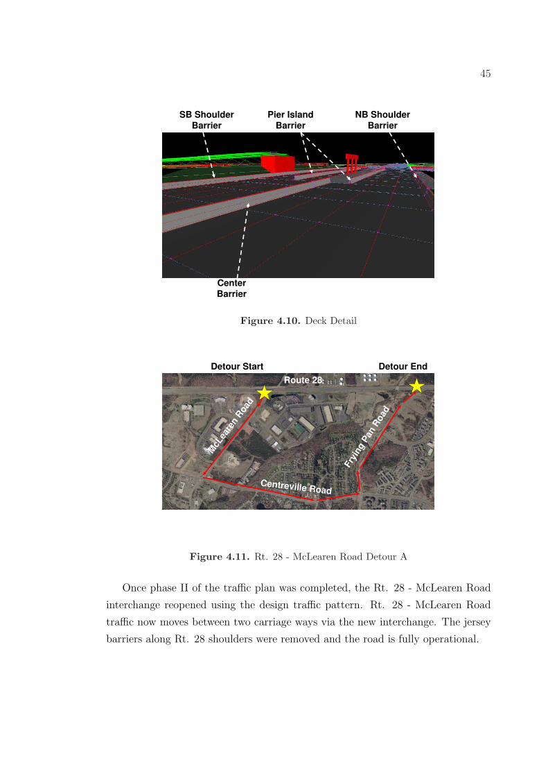
travel ways to provide protection for construction operations throughout ramp
construction. Also, a central island was constructed around the bridge pier con-
struction area using jersey barriers. Figure 4.10 details the traffic control measures
for Rt. 28 during phase I.
Phase II of the traffic control plan included the demolition of the McLearen
44
ConcreteDeck
AsphaltPavement
Concrete Median
Figure 4.8. Deck Detail
Existing McLearen Road
Ramp A Partial Construction
Existing Rt. 28 –McLearen Intersection
Figure 4.9. Traffic Plan: Phase I
Road - Rt. 28 intersection, completion of ramp A, and the tie in between new
and existing McLearen Road. During this phase, the Rt. 28 - McLearen Road
intersection was shut down, while traffic was diverted to different entry and exit
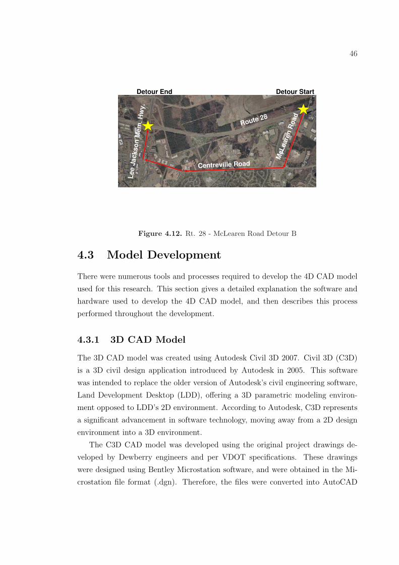
points along Rt. 28. Phase II of the traffic plan lasted thirty days. Figure 4.11
and figure 4.12 detail the detour routes for Rt. 28 - McLearen road traffic.
45
CenterBarrier
NB Shoulder Barrier
Pier Island Barrier
SB Shoulder Barrier
Figure 4.10. Deck Detail
Route 28
McL
eare
n R
oad
Centreville Road
Fry
ing P
anR
oad
Detour Start Detour End
Figure 4.11. Rt. 28 - McLearen Road Detour A
Once phase II of the traffic plan was completed, the Rt. 28 - McLearen Road
interchange reopened using the design traffic pattern. Rt. 28 - McLearen Road
traffic now moves between two carriage ways via the new interchange. The jersey
barriers along Rt. 28 shoulders were removed and the road is fully operational.
46
Route 28
McL
eare
nR
oad
Centreville Road
Lee
Jackso
nM
em
.H
wy.
Detour StartDetour End
Figure 4.12. Rt. 28 - McLearen Road Detour B
4.3 Model Development
There were numerous tools and processes required to develop the 4D CAD model
used for this research. This section gives a detailed explanation the software and
hardware used to develop the 4D CAD model, and then describes this process
performed throughout the development.
4.3.1 3D CAD Model
The 3D CAD model was created using Autodesk Civil 3D 2007. Civil 3D (C3D)
is a 3D civil design application introduced by Autodesk in 2005. This software
was intended to replace the older version of Autodesk’s civil engineering software,
Land Development Desktop (LDD), offering a 3D parametric modeling environ-
ment opposed to LDD’s 2D environment. According to Autodesk, C3D represents
a significant advancement in software technology, moving away from a 2D design
environment into a 3D environment.
The C3D CAD model was developed using the original project drawings de-
veloped by Dewberry engineers and per VDOT specifications. These drawings
were designed using Bentley Microstation software, and were obtained in the Mi-
crostation file format (.dgn). Therefore, the files were converted into AutoCAD
47
file format (.dwg) using the export function in Microstation V.8 so they could be
opened in C3D. This allowed the manipulation and redevelopment of the 2D design
into a 3D model.
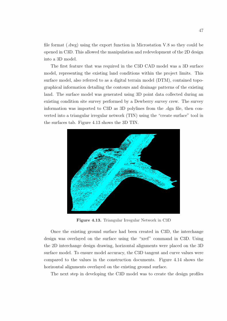
The first feature that was required in the C3D CAD model was a 3D surface
model, representing the existing land conditions within the project limits. This
surface model, also referred to as a digital terrain model (DTM), contained topo-
graphical information detailing the contours and drainage patterns of the existing
land. The surface model was generated using 3D point data collected during an
existing condition site survey performed by a Dewberry survey crew. The survey
information was imported to C3D as 3D polylines from the .dgn file, then con-
verted into a triangular irregular network (TIN) using the “create surface” tool in
the surfaces tab. Figure 4.13 shows the 3D TIN.
Figure 4.13. Triangular Irregular Network in C3D
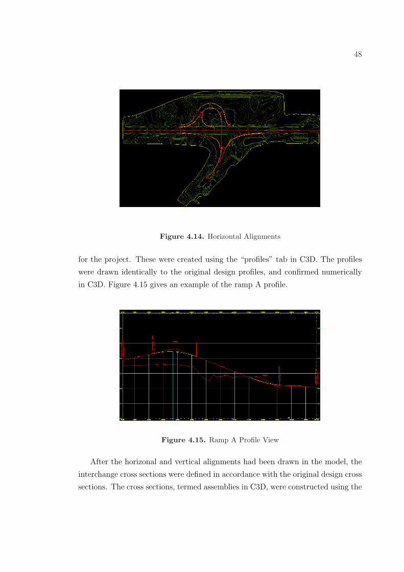
Once the existing ground surface had been created in C3D, the interchange
design was overlayed on the surface using the “xref” command in C3D. Using
the 2D interchange design drawing, horizontal alignments were placed on the 3D
surface model. To ensure model accuracy, the C3D tangent and curve values were
compared to the values in the construction documents. Figure 4.14 shows the
horizontal alignments overlayed on the existing ground surface.
The next step in developing the C3D model was to create the design profiles
48
Figure 4.14. Horizontal Alignments
for the project. These were created using the “profiles” tab in C3D. The profiles
were drawn identically to the original design profiles, and confirmed numerically
in C3D. Figure 4.15 gives an example of the ramp A profile.
Figure 4.15. Ramp A Profile View
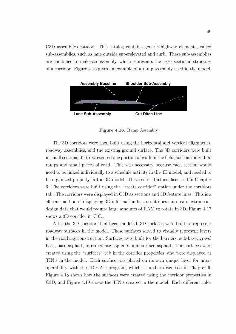
After the horizonal and vertical alignments had been drawn in the model, the
interchange cross sections were defined in accordance with the original design cross
sections. The cross sections, termed assemblies in C3D, were constructed using the
49
C3D assemblies catalog. This catalog contains generic highway elements, called
sub-assemblies, such as lane outside superelevated and curb. These sub-assemblies
are combined to make an assembly, which represents the cross sectional structure
of a corridor. Figure 4.16 gives an example of a ramp assembly used in the model.
Lane Sub-Assembly Cut Ditch Line
Assembly Baseline Shoulder Sub-Assembly
Figure 4.16. Ramp Assembly
The 3D corridors were then built using the horizontal and vertical alignments,
roadway assemblies, and the existing ground surface. The 3D corridors were built
in small sections that represented one portion of work in the field, such as individual
ramps and small pieces of road. This was necessary because each section would
need to be linked individually to a schedule activity in the 4D model, and needed to
be organized properly in the 3D model. This issue is further discussed in Chapter
6. The corridors were built using the “create corridor” option under the corridors
tab. The corridors were displayed in C3D as sections and 3D feature lines. This is a
efficent method of displaying 3D information because it does not create extraneous
design data that would require large amounts of RAM to rotate in 3D. Figure 4.17
shows a 3D corridor in C3D.
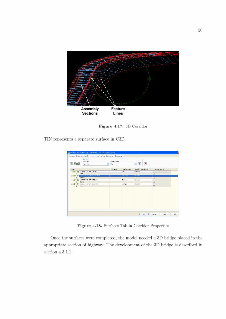
After the 3D corridors had been modeled, 3D surfaces were built to represent
roadway surfaces in the model. These surfaces served to visually represent layers
in the roadway construction. Surfaces were built for the barriers, sub-base, gravel
base, base asphalt, intermediate asphalts, and surface asphalt. The surfaces were
created using the “surfaces” tab in the corridor properties, and were displayed as
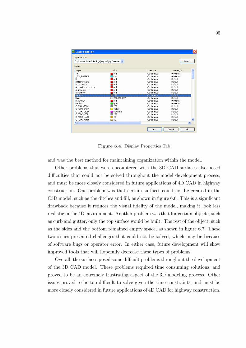
TIN’s in the model. Each surface was placed on its own unique layer for inter-
operability with the 4D CAD program, which is further discussed in Chapter 6.
Figure 4.18 shows how the surfaces were created using the corridor properties in
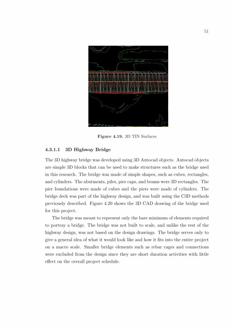
C3D, and Figure 4.19 shows the TIN’s created in the model. Each different color
50
AssemblySections
FeatureLines
Figure 4.17. 3D Corridor
TIN represents a separate surface in C3D.
Figure 4.18. Surfaces Tab in Corridor Properties
Once the surfaces were completed, the model needed a 3D bridge placed in the
appropriate section of highway. The development of the 3D bridge is described in
section 4.3.1.1.
51
Figure 4.19. 3D TIN Surfaces
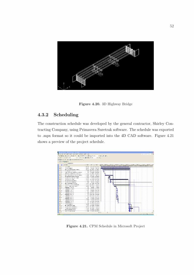
4.3.1.1 3D Highway Bridge
The 3D highway bridge was developed using 3D Autocad objects. Autocad objects
are simple 3D blocks that can be used to make structures such as the bridge used
in this research. The bridge was made of simple shapes, such as cubes, rectangles,
and cylinders. The abutments, piles, pier caps, and beams were 3D rectangles. The
pier foundations were made of cubes and the piers were made of cylinders. The
bridge deck was part of the highway design, and was built using the C3D methods
previously described. Figure 4.20 shows the 3D CAD drawing of the bridge used
for this project.
The bridge was meant to represent only the bare minimum of elements required
to portray a bridge. The bridge was not built to scale, and unlike the rest of the
highway design, was not based on the design drawings. The bridge serves only to
give a general idea of what it would look like and how it fits into the entire project
on a macro scale. Smaller bridge elements such as rebar cages and connections
were excluded from the design since they are short duration activities with little
effect on the overall project schedule.
52
Figure 4.20. 3D Highway Bridge
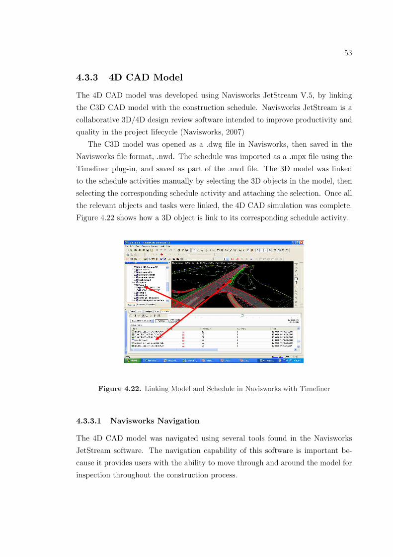
4.3.2 Scheduling
The construction schedule was developed by the general contractor, Shirley Con-
tracting Company, using Primavera Suretrak software. The schedule was exported
to .mpx format so it could be imported into the 4D CAD software. Figure 4.21
shows a preview of the project schedule.
Figure 4.21. CPM Schedule in Microsoft Project
53
4.3.3 4D CAD Model
The 4D CAD model was developed using Navisworks JetStream V.5, by linking
the C3D CAD model with the construction schedule. Navisworks JetStream is a
collaborative 3D/4D design review software intended to improve productivity and
quality in the project lifecycle (Navisworks, 2007)
The C3D model was opened as a .dwg file in Navisworks, then saved in the
Navisworks file format, .nwd. The schedule was imported as a .mpx file using the
Timeliner plug-in, and saved as part of the .nwd file. The 3D model was linked
to the schedule activities manually by selecting the 3D objects in the model, then
selecting the corresponding schedule activity and attaching the selection. Once all
the relevant objects and tasks were linked, the 4D CAD simulation was complete.
Figure 4.22 shows how a 3D object is link to its corresponding schedule activity.
Figure 4.22. Linking Model and Schedule in Navisworks with Timeliner
4.3.3.1 Navisworks Navigation
The 4D CAD model was navigated using several tools found in the Navisworks
JetStream software. The navigation capability of this software is important be-
cause it provides users with the ability to move through and around the model for
inspection throughout the construction process.
54
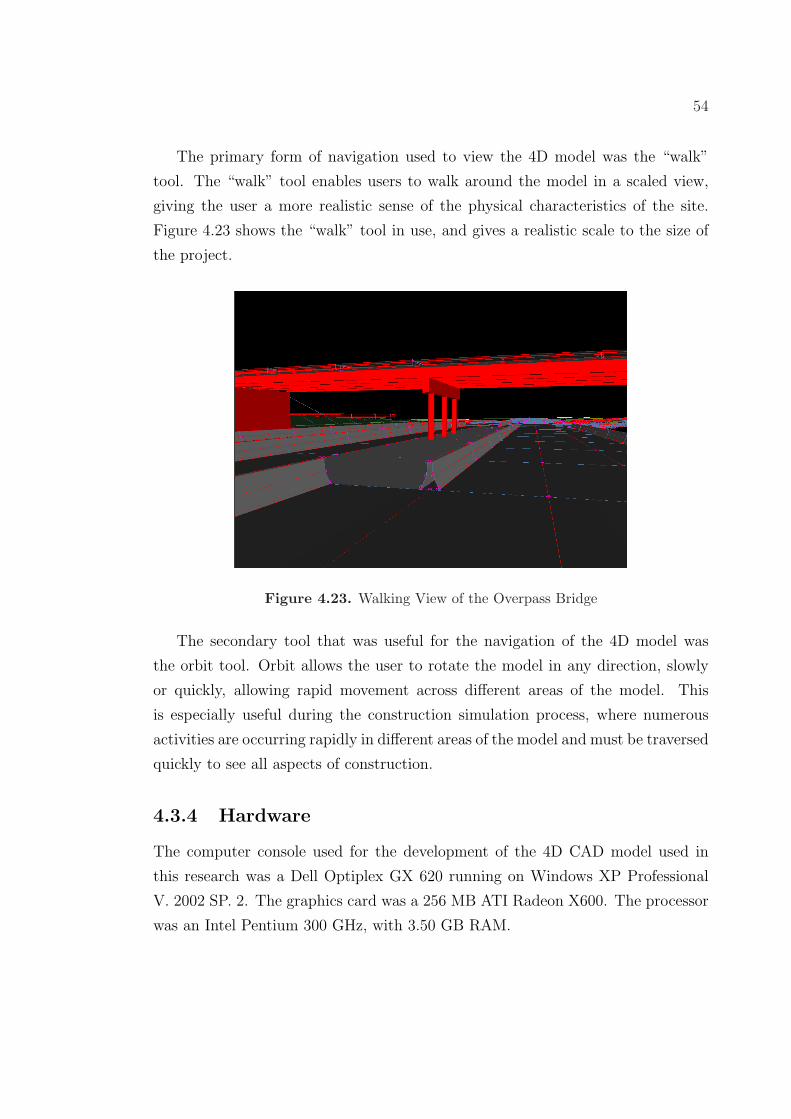
The primary form of navigation used to view the 4D model was the “walk”
tool. The “walk” tool enables users to walk around the model in a scaled view,
giving the user a more realistic sense of the physical characteristics of the site.
Figure 4.23 shows the “walk” tool in use, and gives a realistic scale to the size of
the project.
Figure 4.23. Walking View of the Overpass Bridge
The secondary tool that was useful for the navigation of the 4D model was
the orbit tool. Orbit allows the user to rotate the model in any direction, slowly
or quickly, allowing rapid movement across different areas of the model. This
is especially useful during the construction simulation process, where numerous
activities are occurring rapidly in different areas of the model and must be traversed
quickly to see all aspects of construction.
4.3.4 Hardware
The computer console used for the development of the 4D CAD model used in
this research was a Dell Optiplex GX 620 running on Windows XP Professional
V. 2002 SP. 2. The graphics card was a 256 MB ATI Radeon X600. The processor
was an Intel Pentium 300 GHz, with 3.50 GB RAM.
Chapter 5Data Collection and Results:
Identifying the Best Applications of
4D CAD for Highway Construction
Projects
This chapter presents the research methods and results performed in this thesis
to determine the best applications of 4D CAD for highway construction. The
scaled questionnaire, open ended questions, and focus group discussions are first
described, then the results are presented. The data is then analyzed and discussed
in-depth, representing the views and opinions expressed by the research groups
used for the research.
5.1 Research Groups
This research was performed using three separate groups of highway construction
professionals. Each group was from a different construction company, and for
the remainder of this thesis are referred to as Contractor 1, Contractor 2, and
Contractor 3. The contractors all have significant highway construction experience
on complex construction projects, and served as the primary resource for data
collected in this thesis.
56
Contractors 1 and 3 were located in Northern Virginia, and worked primarily in
the greater Washington D.C. area. Contractor 2 was located in Central Pennsyl-
vania, and worked on projects throughout the state. The experience range of the
professionals in the groups was from one year to thirty years, representing entry
level engineers to a President/CEO. This wide range of construction professionals
is valuable for research purposes because it represents a broad perspective of high-
way construction experts, and does not limit the research data to a specific age or
experience level. The opinions expressed in this thesis are based on the thoughts
and suggestions of the highway construction professionals surveyed, and represent
their opinions regarding 4D CAD in highway construction.
5.2 Research Meeting Procedure
The data collection was performed at the offices of the contracting companies
participating in the research studies. The presentation and data collection were
done in the offices conference room, by projecting the presentation and 4D CAD
model on a screen in the front of the room. Research participants viewed the
presentation from their seats, as the slide show and model were presented by the
researcher. The research meetings typically lasted ninety minutes.
The research meetings began with an introductory slide show giving an overview
and background to the research topic. The slide show described the purpose and
objective of the study, and how the participants relate to research being performed.
Then, a definition and example of 4D CAD was given to familiarize the group with
4D CAD technology. This helped define a baseline of understanding among the
research participants, since most were not familiar with 4D CAD technology. The
4D CAD example showed the erection of a twelve story apartment building, con-
veying the essential concepts of 4D CAD and giving the group a general idea of
what a 4D CAD model looks like. Next, the case study project was introduced.
The introduction defined the goals and objectives of the case study, then outlined
project details such as the work requirements, schedule, and project team. Once
the case study had been introduced, the 4D CAD model of the project was shown.
The model was first shown at full speed, without any comments through the visu-
alization. This gave the research group their first ideas and impressions of the 4D
57
highway model. Then, the visualization was played a second time, slowly moving
step by step through the progression of work with an explanation of each activity
occurring in the visualization. This gave the research team a more detailed look at
the 4D CAD model, and a better understanding of the project simulation. The 4D
CAD visualization was then removed from the screen and the research exercises
were performed. These exercises included a scaled questionnaire, open ended ques-
tions, and a focus group discussion, and are discussed in detail in sections 5.3, 5.4,
and 5.5. Once the exercises were completed, the research meeting was concluded.
5.3 Exercise 1 - Scaled Questionnaire
The objective of scaled questionnaire was to collect quantitative data from the
research participants that could be used to determine the best applications of 4D
CAD for highway construction projects. The questionnaire asked participants to
rank their perception of the benefits of 4D CAD in numerous different highway
construction applications on a scale of 0 - 10, 0 being no benefit and 10 being
high benefit. The survey consisted of thirteen questions divided into two general
categories, I. Planning and Scheduling (PS) and II. Communication (C). These
two categories were chosen because previous 4D CAD research had shown them
to be the most beneficial areas for 4D CAD applications in building construction.
Table 5.1 summarizes these publications, and describes the benefits shown in each
paper.
Table 5.1. Summary of Publications Documenting 4D CAD Benefits
Name Publication Results
Messner and Lynch (2002) A Construction Simulation Model for Pro-duction Planning at the Pentagon Renova-tion Project
Improved Production Plan
Yerrapathruni (2003) Using 4D CAD and Immersive Virtual En-vironments to Improve Construction Plan-ning
Improved Sequencing
Koo and Fisher (2000) Feasibility Study of 4D CAD in Commer-cial Construction
Better Understanding of Schedule, Im-proved Schedule Communication
Fisher and Kunz (2004) The Scope and Role of Information Tech-nology in Construction
Gain Better Visual Understanding of Fa-cility
Otto et al. (2005) Expanding the Boundaries of Virtual Re-ality for Building Design and Construction
Importance of Visualization for Communi-cation
58
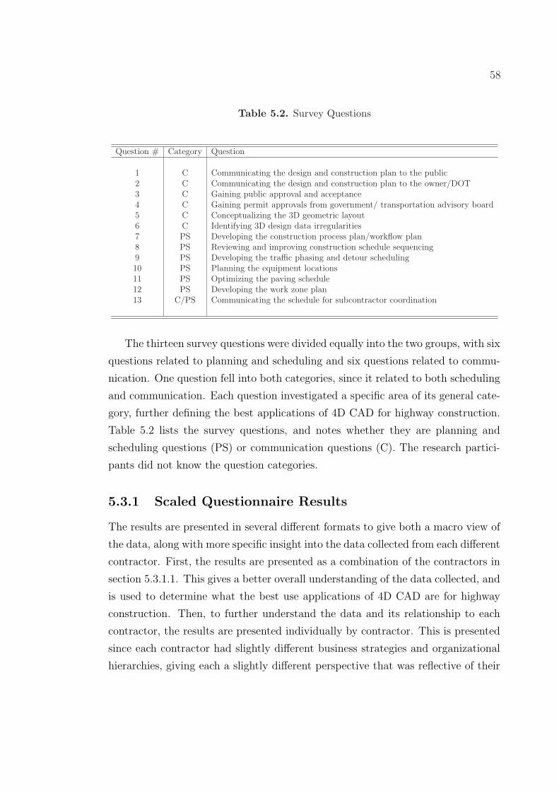
Table 5.2. Survey Questions
Question # Category Question
1 C Communicating the design and construction plan to the public2 C Communicating the design and construction plan to the owner/DOT3 C Gaining public approval and acceptance4 C Gaining permit approvals from government/ transportation advisory board5 C Conceptualizing the 3D geometric layout6 C Identifying 3D design data irregularities7 PS Developing the construction process plan/workflow plan8 PS Reviewing and improving construction schedule sequencing9 PS Developing the traffic phasing and detour scheduling10 PS Planning the equipment locations11 PS Optimizing the paving schedule12 PS Developing the work zone plan13 C/PS Communicating the schedule for subcontractor coordination
The thirteen survey questions were divided equally into the two groups, with six
questions related to planning and scheduling and six questions related to commu-
nication. One question fell into both categories, since it related to both scheduling
and communication. Each question investigated a specific area of its general cate-
gory, further defining the best applications of 4D CAD for highway construction.
Table 5.2 lists the survey questions, and notes whether they are planning and
scheduling questions (PS) or communication questions (C). The research partici-
pants did not know the question categories.
5.3.1 Scaled Questionnaire Results
The results are presented in several different formats to give both a macro view of
the data, along with more specific insight into the data collected from each different
contractor. First, the results are presented as a combination of the contractors in
section 5.3.1.1. This gives a better overall understanding of the data collected, and
is used to determine what the best use applications of 4D CAD are for highway
construction. Then, to further understand the data and its relationship to each
contractor, the results are presented individually by contractor. This is presented
since each contractor had slightly different business strategies and organizational
hierarchies, giving each a slightly different perspective that was reflective of their
59
company. This also gives insight into the opinions of different levels of experience
and employment positions within a group. It is valuable to understand the dif-
ferent perspectives of highway construction professionals relative to their age and
experience because opinions and insights change drastically over an individuals
career. For example, high level management may see certain benefits of 4D CAD
for highway construction that lower level employees may not. This is because
upper management deals with different problems and issues in their job, giving
them a wider perspective into applications of the model. This data is presented in
section 5.3.1.2.
5.3.1.1 Overall Results
The overall results present the combined data from each of the contractors. This
gives quantitative insight into the overall opinions and viewpoints of the contractors
that participated in this research.
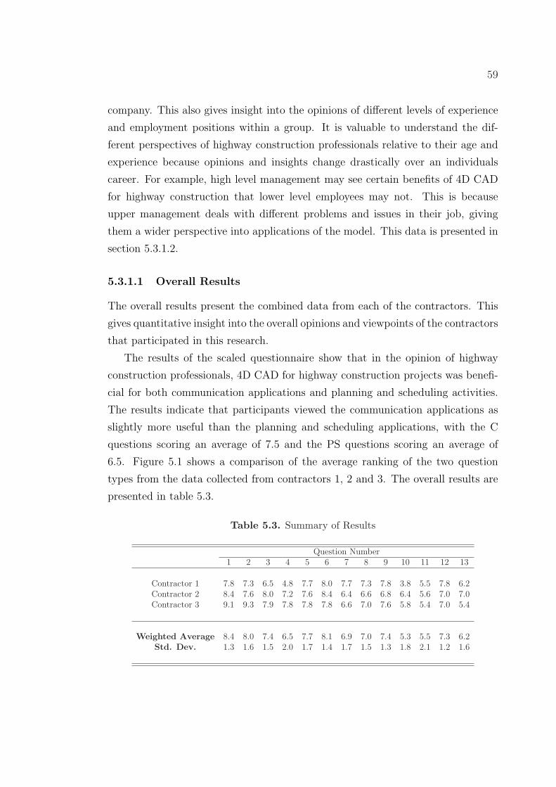
The results of the scaled questionnaire show that in the opinion of highway
construction professionals, 4D CAD for highway construction projects was benefi-
cial for both communication applications and planning and scheduling activities.
The results indicate that participants viewed the communication applications as
slightly more useful than the planning and scheduling applications, with the C
questions scoring an average of 7.5 and the PS questions scoring an average of
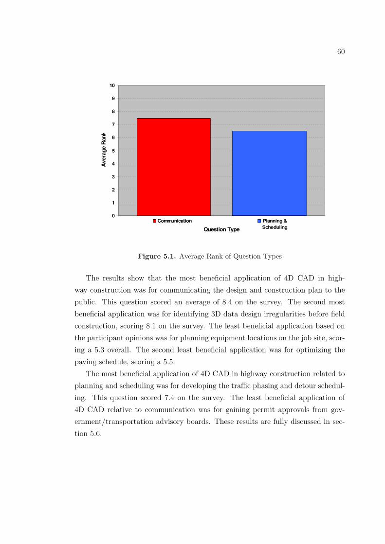
6.5. Figure 5.1 shows a comparison of the average ranking of the two question
types from the data collected from contractors 1, 2 and 3. The overall results are
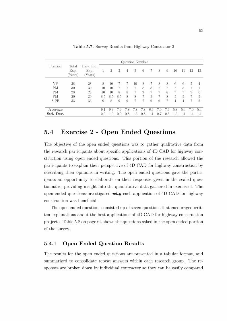
The objective of the open ended questions was to gather qualitative data from
the research participants about specific applications of 4D CAD for highway con-
struction using open ended questions. This portion of the research allowed the
participants to explain their perspective of 4D CAD for highway construction by
describing their opinions in writing. The open ended questions gave the partic-
ipants an opportunity to elaborate on their responses given in the scaled ques-
tionnaire, providing insight into the quantitative data gathered in exercise 1. The
open ended questions investigated why each application of 4D CAD for highway
construction was beneficial.
The open ended questions consisted up of seven questions that encouraged writ-
ten explanations about the best applications of 4D CAD for highway construction
projects. Table 5.8 on page 64 shows the questions asked in the open ended portion
of the survey.
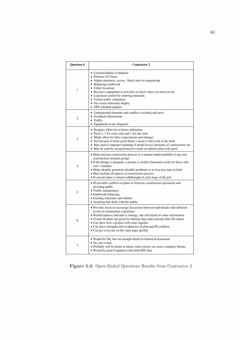
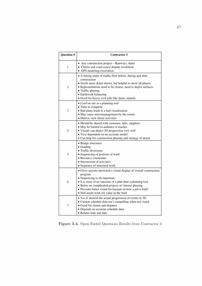
5.4.1 Open Ended Question Results
The results for the open ended questions are presented in a tabular format, and
summarized to consolidate repeat answers within each research group. The re-
sponses are broken down by individual contractor so they can be easily compared
64
Table 5.8. Open Ended Questions
Question # Question
1 Are there other applications in which 4D CAD could be used as a beneficial tool?2 What additional information would be valuable to represent in the 4D CAD visual-
ization?3 What disadvantages might a 4D CAD visualization have related to a project?4 Do you believe a 4D CAD visualization can accurately describe and communicate a
construction strategy? Please explain.5 What is the most important aspect visually in a 4D construction model? (Traffic
Diversion, Pipe layout/storm water, grading and earthwork, equipment, etc.)6 Does a 4D construction model provide better insight into the general construction
strategy? Please explain.7 Does 4D construction visualization environment helps in producing a better AS-
BUILT and Information Model for Owner?
and contrasted for data analysis. Each question showed numerous reoccurring re-
sponses from each individual contractor, leading to concrete conclusions about 4D
CAD for highway construction projects. The results from contractors 1, 2, and 3
are presented respectively in figures 5.2, 5.3 and, 5.4 on pages 65, 66, and 67.
The results from the open ended questions give several specific suggestions
about applications of 4D CAD for highway construction projects. Each question
posed in this portion of the survey shows specific trends in the responses from each
contractor. Common suggestions appeared throughout the surveys for each ques-
tion, independent of the contractor participating at the time. Often, a suggestion
would appear in 2 out of 3 contractors, suggesting a strong correlation between
responses. The most convincing responses appeared across all three contractors,
and represent the best suggestions for each question. These common suggestions,
where all three contractors responded identically, served as the primary evidence
used to support the findings in this research, and represented the most important
issues in the opinions of highway construction professionals. Figure 5.5 shows the
common suggestions given by the highway construction contractors.
65
Question # Contractor 1
1Utility conflicts, overhead and underground.
Phased takeoff
2
Drainage
Existing utilities
Mapping
Traffic analysis
3
Too complex
Confuse less technically savvy staff
Time consuming to develop and update
Need high level of detail
4
See design/ scheduling conflicts
Identify errors in plans
Helps buy-in
Good overview of project & schedule
Complex projects w/ many stages & traffic shifts
5
Maintenance of traffic to ensure sufficient area for construction
Identify conflicts
Maintain traffic
Maintain drainage
Grading/earthwork
6
Visually depict how project is constructed
Reinforce a construction schedule
Show alternative sequences of work to find best option
7Visual flow of work
Would be difficult and lot of work
Figure 5.2. Open Ended Questions Results from Contractor 1
66
Question # Contractor 2
1
Constructability evaluation
Defense of Claims
Adjust structures, access, block outs for sequencing
Balancing earthwork
Utility locations
Resource equipment to activities to know what you need on site
Logistical control for ordering materials
Virtual traffic simulation
On-screen milestone display
GPS schedule updates
2
Underground elements and conflicts (existing and new)
Overhead obstructions
Traffic
Equipment in use diagrams
3
Requires effort for in house utilization
Need 2, 1 for early start and 1 for late start
Might allow for false expectations and changes
Just because it looks good doesn’t mean it will work in the field
May lead to improper planning if model leaves elements of construction out
May be used by inexperienced to make an inferior plan look good
4
Helps present construction process in a manner understandable to any non
construction oriented groups
If the design is adequate, a picture is worth a thousand words for those who
can’t visualize.
Helps identify potential schedule problems so to lose less time in field
Must include all aspects of construction process
Everyone takes a virtual walkthrough of each stage of the job
5
ID possible conflicts in plans or between construction operations and
traveling public
Traffic maintenance
Earthwork balancing
Existing structures and utilities
Anything that deals with the public
6
Provides focus to encourage discussion between individuals with different
levels of construction experience
Would improve and add to strategy, but still based on same information
Visual 3D plans are great for sharing ideas and concepts that 2D cannot
Can show how a project will come together
Can show strengths and weaknesses of plan and ID conflicts
Can get everyone on the same page quickly
7
Would be OK, but not enough detail for historical document
No, just visual
Probably will be better in future when owners are more computer literate
Would be good if updated with field GPS data
Figure 5.3. Open Ended Questions Results from Contractor 2
67
Question # Contractor 3
1
Any construction project – Runways, dams
Claims and court cases/ dispute resolution
GPS modeling excavation
2
A timing study of traffic flow before, during and after
construction
Needs more detail shown, but helpful to show all phases
Representations need to be clearer, need to depict surfaces
Traffic phasing
Earthwork balancing
Good for heavy civil jobs like dams, tunnels
3
Used on site as a planning tool
Time to complete
Bad plans leads to a bad visualization
May cause micromanagement by the owner
Hard to view linear activities
4
Should be shared with customer, subs, suppliers
May be limited to audience it reaches
Visuals can depict 3D progression very well
Very dependent on an accurate model
Can help for construction phasing and strategy of attack
5
Bridge structures
Grading
Traffic diversions
Sequencing of portions of work
Resource constraints
Intersection of activities
Sequence of structural work
6
Gives anyone interested a visual display of overall construction
program
Sequencing is all important
It is more of an outcome of a plan than a planning tool
Better on complicated projects w/ intense phasing
Provides better visual for layman on how a job is built
Still needs work for value in the field
7
Yes if showed the actual progression of events in 3D
Current schedule data isn’t compelling when not visual
Good for claims and disputes
Depends on accurate schedule data
Relates time and date
Figure 5.4. Open Ended Questions Results from Contractor 3
68
Suggestion FrequencyQuestion
# 3 out of 3 2 out of 3
1
• None • Defense of claims
• GPS modeling
• Utility conflicts/locations
2• Traffic phasing/analysis • Underground and overhead utilities
3• Time to complete/level of detail • None
4 • Scheduling/phasing • Need an accurate model
5
• Traffic maintenance
• Earthwork applications
• Identify schedule conflicts
• None
6• Sequencing
• Good visual depiction of construction
• None
7 • Would be difficult • Require a lot of work
Figure 5.5. Common Suggestions to Open Ended Questions
69
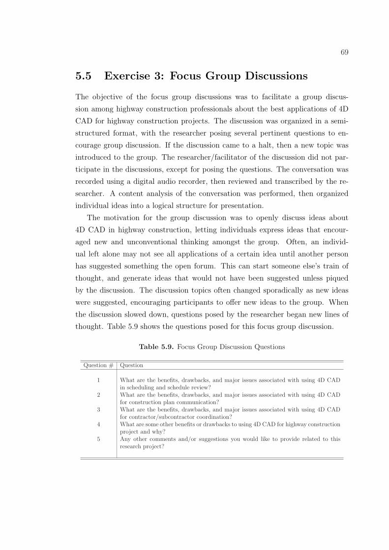
5.5 Exercise 3: Focus Group Discussions
The objective of the focus group discussions was to facilitate a group discus-
sion among highway construction professionals about the best applications of 4D
CAD for highway construction projects. The discussion was organized in a semi-
structured format, with the researcher posing several pertinent questions to en-
courage group discussion. If the discussion came to a halt, then a new topic was
introduced to the group. The researcher/facilitator of the discussion did not par-
ticipate in the discussions, except for posing the questions. The conversation was
recorded using a digital audio recorder, then reviewed and transcribed by the re-
searcher. A content analysis of the conversation was performed, then organized
individual ideas into a logical structure for presentation.
The motivation for the group discussion was to openly discuss ideas about
4D CAD in highway construction, letting individuals express ideas that encour-
aged new and unconventional thinking amongst the group. Often, an individ-
ual left alone may not see all applications of a certain idea until another person
has suggested something the open forum. This can start someone else’s train of
thought, and generate ideas that would not have been suggested unless piqued
by the discussion. The discussion topics often changed sporadically as new ideas
were suggested, encouraging participants to offer new ideas to the group. When
the discussion slowed down, questions posed by the researcher began new lines of
thought. Table 5.9 shows the questions posed for this focus group discussion.
Table 5.9. Focus Group Discussion Questions
Question # Question
1 What are the benefits, drawbacks, and major issues associated with using 4D CADin scheduling and schedule review?
2 What are the benefits, drawbacks, and major issues associated with using 4D CADfor construction plan communication?
3 What are the benefits, drawbacks, and major issues associated with using 4D CADfor contractor/subcontractor coordination?
4 What are some other benefits or drawbacks to using 4D CAD for highway constructionproject and why?
5 Any other comments and/or suggestions you would like to provide related to thisresearch project?
70
5.5.1 Focus Group Discussions Results
The focus group discussions results are presented using a content analysis that
systematically analyzed the discussions performed with contractors 2 and 3. The
content analysis aimed to logically classify the conversations between the highway
construction professionals to develop concrete messages within their discussion.
This is important because these ideas serve as the primary data used to support
the claims put forth in this research. The content analysis also aimed to identify
common instances of discussion content independent of the research group. These
common discussion instances are identified in the content analysis maps using a
color coding system described in figure 5.6. The blue highlighted text represents
content taken from contractor 2’s focus group discussion. The red highlighted text
represents contractor 3’s discussion. The green highlighted text represents common
content that was discussed by both contractors who participated in the focus group
discussions. Contractor 1 did not participate in a focus group discussion, and is
therefore not represented in this data.
The content analysis consisted of three common categories that the discussion
could be classified into. These categories were scheduling and schedule review,
planning and phasing, and communications. These are similar to those categories
defined in the scaled questionnaire and open ended questions, but have separated
the planning and scheduling group (PS) into two separate groups to gain further
insight into the applications of 4D CAD in highway construction. The content was
further classified into four sub-categories once placed into the general category.
These sub-categories were positive, negative, issues, and other.
- Contractor #2
- Contractor #3
- Contractor #2 & 3
Figure 5.6. Text Color Key for Content Analysis
71
Scheduling &
Schedule Review
Positives
• Helps project team understand schedule
visually• Highlight milestones
in schedule visually, such as traffic shift
• Good for design build work
Negatives
• Little benefit on small scale projects
• Unnecessary for most subs• Still need to understand
scheduling to use properly• Scheduling skills still required
for 4D
Issues
• May be required to follow engineers schedule, leaving little flexibility for change
• Activities happen in field before 4D is completed
• People may reject GC schedule and do their own way
• Must be user friendly• Really only shows outcome of a good
schedule
Other
• Use field GPS data to update schedule
• Tie schedule to cost in 4D CAD• Help communication of
schedule from project manager to scheduler
• Can teach inexperiencedschedulers
• More benefit on large scale projects
• Identify errors missed
in Gantt chart• Confirm schedule logic• Early detection of
activity clashes
Figure 5.7. Scheduling and Schedule Review Content Analysis
The results of the focus group discussions give numerous valuable insights and
suggestions about the opinions of highway construction professionals regarding ap-
plications of 4D CAD for highway construction projects. Each contractor presented
both unique and common ideas throughout their discussions, and introduced ad-
ditional research topics that had not been considered throughout this research.
Some common ideas presented regarding scheduling and schedule review were
that 4D CAD can help identify errors and omissions missed in the Gantt chart
representation of the schedule. Another common idea was that people, both in-
ternal or external, may reject the 4D CAD technology and follow their traditional
methods of scheduling. One unique opinion presented regarding scheduling and
schedule review was that the schedule could be tied to GPS earthwork systems in
order to update the schedule automatically.
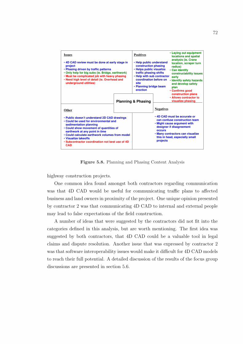
One common idea expressed by both contractors regarding planning and phas-
ing was that 4D CAD could be a valuable tool for developing a site safety plan.
One unique opinion presented by contractor 3 regarding planning and phasing
was that 4D CAD is much more valuable if applied to large scale, heavily phased
72
Planning & Phasing
Positives
• Help public understand construction phasing
• Helps public visualize traffic phasing shifts
• Help with sub contractor coordination before on site
• Planning bridge beam
erection
Negatives
• 4D CAD must be accurate or can confuse construction team
• Might cause argument with designer if disagreement occurs
• Many contractors can visualize this in head, especially small projects
Issues
• 4D CAD review must be done at early stage in project
• Phasing driven by traffic patterns• Only help for big subs (ie. Bridge, earthwork)• Must be complicated job with heavy phasing• Need high level of detail (ie. Overhead and
underground utilities)
Other
• Public doesn’t understand 2D CAD drawings• Could be used for environmental and
sedimentation planning• Could show movement of quantities of
earthwork at any point in time• Could calculate earthwork volumes from model• Visualize takeoffs• Subcontractor coordination not best use of 4D
CAD
• Laying out equipment
locations and spatial analysis (ie. Crane location, scraper turn radius)
• Can identify constructability issues
early• Identify safety hazards
and develop safety plan
• Confirms good construction plans
• Allows contractor to visualize phasing
Figure 5.8. Planning and Phasing Content Analysis
highway construction projects.
One common idea found amongst both contractors regarding communication
was that 4D CAD would be useful for communicating traffic plans to affected
business and land owners in proximity of the project. One unique opinion presented
by contractor 2 was that communicating 4D CAD to internal and external people
may lead to false expectations of the field construction.
A number of ideas that were suggested by the contractors did not fit into the
categories defined in this analysis, but are worth mentioning. The first idea was
suggested by both contractors, that 4D CAD could be a valuable tool in legal
claims and dispute resolution. Another issue that was expressed by contractor 2
was that software interoperability issues would make it difficult for 4D CAD models
to reach their full potential. A detailed discussion of the results of the focus group
discussions are presented in section 5.6.
73
Communication
Positives
• Very good for describing construction
to non-construction audience
• Helps laymen visualize project (ie. Town meeting)
Negatives
• May present well but still not good ideas passed along
• Lead to false expectations from owner or public
Issues
• DOT’s slow to adopt/require new technologies
Other
• Could show traffic fly through of jobsite• May improve driver comfort level
• Put message system to reference website showing 4D CAD visuals throughout time
• Designers could present to bidders to show project intent
• Show affected businesses/landowners traffic plans
• Use at safety meeting to visually communicate safety hazards
Figure 5.9. Communication Content Analysis
5.6 Discussion of Results
The discussion of the results aims to consolidate common ideas and opinions ex-
pressed by the highway construction professionals throughout the scaled question-
naire, open ended questions, and focus group discussions. These common themes
collected throughout the research are supported by both the qualitative and quan-
titative data, and serve as a foundation for the conclusions put forth in this thesis.
This section also includes other specific examples and quotations collected during
the open ended question and focus group discussion that give valuable insight into
4D CAD for highway construction.
The discussion is broken down into four separate categories to maintain struc-
ture throughout this section. Section 5.6.1, starts by giving an overview of the
general findings collected in this research, and offers insight into the overall opin-
ions of the researcher and research participants. Section 5.6.2 discusses results
related to planning and scheduling, section 5.6.3 discusses communication appli-
cations of 4D CAD, and section 5.6.4 discusses other miscellaneous results that do
74
not fit into the prior categories.
5.6.1 General Discussion
The results gathered in this research suggest an overall optimistic view of 4D
CAD for highway construction projects in the opinion of highway construction
professionals. For example, the scaled questionnaire asked each participant to
rank their perception of the benefit of 4D CAD for highway construction on a
scale of 0 - 10, where 0 was no benefit and 10 was high benefit. The lowest average
score returned on this questionnaire was 5.3, which shows that although this is
not the best application of 4D CAD, there still is moderate benefit. No individual
gave a zero response for any of the applications in question, showing that in all
instances surveyed, the person saw at least some benefit in 4D CAD for highway
construction.
The highway construction professionals all gave enthusiastic responses through-
out the data collection and discussions in this research, and suggested many new
applications and ideas that are worth exploration in future research. Much of the
professional outlook was slightly skeptical of 4D CAD in the highway construction
industry today, but could see the bigger picture of how this technology will apply
to the future of their industry. All three contractors noted that the 4D models
needed substantial improvement from the case study shown, but could be widely
adopted once improvements are made. One research participant commented that
“4D CAD models are the next logical step” in the progression of planning, schedul-
ing and communication technology in the highway construction industry. This
slightly skeptical, but positive outlook embodies the views expressed by all three
contractors.
5.6.2 Planning and Scheduling
The data collected throughout this research shows that 4D CAD is beneficial for
numerous planning and scheduling activities for highway construction projects.
Specific examples and instances are discussed, and have definitive evidence of their
importance in this research.
The results from the scaled questionnaire identified traffic phasing and detour
75
scheduling as the most beneficial applications 4D CAD for planning and schedul-
ing activities. This idea was supported throughout exercises 1, 2, and 3, and was
reinforced in a quote from a focus group discussion where the vice president of
contractor 2 says
“I see huge benefit any time you get a complex traffic control plan, it’s usually
because you have a complex phased construction. That’s were I see this having the
most benefit”
Contractor 2 points out that 4D CAD is extremely valuable in highway construc-
tion because often times the construction phasing plans are driven by the traffic
patterns required throughout the construction project. Highways must maintain a
consistent flow of traffic throughout construction to enable transportation across
the area. This requires detailed traffic control planning to ensure the project op-
erates smoothly and safely for both the contractor and traveling public. Several
traffic control suggestions were also made in the open ended questions. In question
2, all three contractors suggested that traffic phasing would be valuable additional
information that could be included into the 4D CAD model, and would help traffic
planning and scheduling before the construction process. Also, in question 5, all
three contractors responded that the most important aspect visually in a 4D CAD
model was traffic maintenance. The importance of traffic modeling and sequenc-
ing in 4D CAD for highway construction is paramount to developing a beneficial
4D model. Suggestions throughout the data collection shows that this aspect of
highway construction should be closely considered and included when developing
a 4D CAD model for highway construction projects.
The scaled questionnaire ranks “developing a work zone plan” as the second
most beneficial aspect of 4D CAD for highway construction projects, and “devel-
oping a construction process/workflow plan” as third. These ideas are similar, and
are both supported by common comments expressed in the open ended questions
and the focus group discussions. Contractor 3 stated in the focus group discussion
that 4D CAD allows contractors to develop and confirm construction plans and
work zone phasing visually, which can help identify problems that were omitted
on the 2D drawings and Gantt chart. This is valuable because field work zone
conflicts occurring cause delays in work, ultimately costing the contractors time
and money. If these issues had been identified in a 4D CAD review, these conflicts
76
may have been prevented. In the open ended questions, one participant noted that
“If the 4D model shows visually a flaw in the sequence one time per project,
it is successful.”
This quote sums up the importance of developing accurate construction plans and
work zones, and highlights the value a 4D CAD model can offer for work zone
planning.
Another benefit of 4D CAD in highway construction projects is in scheduling
and schedule review. Highway construction professionals identified several appli-
cations of scheduling benefits in all three of the exercises, including superior un-
derstanding of scheduling logic, and easy detection of activity clashes. The focus
group discussions suggested that 4D CAD can help the project team understand
the schedule visually, and can get the everyone on the same page quickly. This
is important for the general contractor because it is critical that he understand
construction schedule intimately for each project. If 4D CAD can increase sched-
ule understanding, it will improve the overall team performance and improve the
project as a whole. Contractor 2 suggested in that this would be especially benefi-
cial in design-build work because projects require careful scheduling for maximum
performance. The tighter schedule deadlines and stricter penalties make 4D CAD
ideal for planning and scheduling when working under these conditions.
The results of the focus group discussions also suggests some drawbacks and
issues associated with using 4D CAD for scheduling and schedule review. Both
contractors said that one drawback was that people such as subcontractors, owners,
and internal personnel may reject the schedule shown in the 4D CAD simulation
and prefer to do the work their own way. This is a difficult problem for the general
contractor because the success of a project is highly dependent on proper execution
of the schedule. If people do not agree with the 4D CAD schedule, it would not be
valuable because it wouldn’t represent the true field construction. This illustrates
the need to get subcontractors and other parties involved in early schedule reviews
of the model. This would improve the schedule quality and encourage long term
planning before the project begins. Another drawback suggested by contractor 3
was that a 4D CAD model still requires a good schedule by a person with competent
scheduling skills. The participant noted that a 4D CAD model was an outcome of
a good schedule, and could not make a good schedule itself. This is an important
77
point because the 4D CAD model is highly dependent on the project schedule.
If the schedule is not logical for construction, than the 4D CAD model will not
be valuable for schedule and schedule review. One participant from contractor 2
summarized this problem saying “garbage in, garbage out.” This shows that a 4D
CAD model should not be relied on for initial schedule development, but should
be used as a tool to review and improve the original project schedule.
Other benefits of 4D CAD for highway construction when applied to planning
and scheduling were in planning on-site equipment locations. Although equipment
planning scored relatively low in the scaled questionnaire, several suggestions dur-
ing the focus group discussions identified valuable situations in which 4D CAD
could be used for planning equipment locations. One comment from contractor 2
was that a 4D CAD model would be valuable in selecting crane locations for bridge
erection. This is a vital task in the success of any project requiring overpass bridge
construction, and could be used to plan crane pad locations at different periods
throughout the project. Contractor 2 also suggested that a spatial analysis could
be done in the 4D CAD environment where the project team could determine how
many cranes would be needed for a certain activity, and how close they would be
at different points in construction. This could reduce cost by possibly eliminat-
ing one crane on the project. Another example of using 4D CAD for equipment
planning was suggested by contractor 3, where using a model, the project team
could test if certain machines could operate in different areas on the project. In
some cases, grading cannot be done by a scraper because their is not enough space
for the machine to turn around. Therefore, bulldozers are used to grade the area
and the scrapers left idle, costing the contractor money. The project team could
spatially test certain areas on the project and evaluate if a machine could or could
not be used in that phase of the project.
The results from the scaled questionnaire shows that using 4D CAD for opti-
mizing paving schedules was not one of the better applications of 4D CAD relative
to the others surveyed. This is explained in a focus group discussion, where both
contractors said that small, individual activities such as paving are not worth-
while to show because of their short duration. Often, paving crews come in on
short notice, and can finish their work quickly without disturbing other trades.
This means that scheduling around the paving crew is not as important as other
78
larger crews. Longer duration activities, such as earthwork, where much of the
project is dependent on that crew are much more beneficial to model in a 4D CAD
simulation.
5.6.3 Communication
The research shows that 4D CAD is beneficial in numerous communication appli-
cations related to highway construction projects. In general, the highway construc-
tion professionals viewed these applications as more beneficial than the planning
and scheduling applications surveyed throughout this research. In the scaled ques-
tionnaire, the communications questions scored an average 7.5, while the planning
and scheduling questions scored a 6.5. The open ended questions and focus group
discussions offer an explanation for why the communication applications are so
beneficial, and how they can be used in the future of 4D CAD for highway con-
struction.
The scaled questionnaire shows that highway construction professionals be-
lieved the most beneficial application of 4D CAD was for “communicating the
design and construction plan to the public.” This claim is supported in the open
ended questions and focus group discussions, where substantial qualitative data
exists to support this idea. In a focus group discussion, a quote from the president
and vice president of contractor 2 describes their opinion of the communication
applications of 4D CAD for highway construction.
President: “I think [4D CAD] would be helpful for describing what your doing
to a non construction audience. You could go to a town meeting, or some other
people who don’t understand construction, and visualize what your going to do.”
VP: “That’s absolutely one of the biggest benefits.”
This quote shows that in the opinion of a president and vice president of a highway
contractor, with a combined 60 years of construction experience, how beneficial a
4D CAD model can be for communication. The open ended questions reiterated
this idea when contractor 3 said that 4D CAD is a valuable tool to visually com-
municate how a job is built to a layman, such as the public.
The reason that communicating the design and construction plan to the public
is so important is because highway construction projects directly effect the daily
79
lives of the public. They are effected in several ways, each giving substantial reason
why they should be cognisant of highway construction projects in their area. The
first way that the public is effected by highway construction is that the highway
facilities being built are for their use, and will be funded with their tax dollars.
Highway construction projects are extremely expensive, and it is important for
every construction project to be justified in the public eye. The public must
believe that each project is going to improve their transportation system, and that
each project is a worthwhile investment of their tax dollars.
This research shows that highway construction professionals believe that a 4D
CAD model would be valuable for communicating a construction project to the
public, and would ultimately give them a better understanding of the design and
construction plan that they are paying for. In the open ended questions and focus
group discussion, contractor 2 notes that the majority of the public does not clearly
understand 2D drawings, making it difficult to communicate the construction plan.
He says that
“I think it [4D CAD] would work very well...because it would lend great credi-
bility to public input. People who don’t understand construction phasing and can’t
just visualize how this is going to work...but if you take people out and you show
them 2D plans then they can’t understand it. If you just fly them through that [4D
CAD model], they can say, oh you have to go do this, and this, and you show them
where traffic goes so they can understand it.”
This quote emphasizes how 4D CAD can give the public a “visual advantage”
in understanding a project, and ultimately a superior understanding of the work
when compared with the 2D design documents.
A second instance in which the public is effected by highway construction is
when they must wait in traffic created during the construction phase of the project.
This costs the traveling public time, money, and frustration, because they must
wait in their car through lane closures and other traffic control measures. A 4D
CAD model would be valuable in this situation because the traffic control plan
could be communicated to drivers before they begin their travel. One suggestion
from contractor 2 was that a message system could be put up as drivers approached
a highway construction project that referred them to a specific website. This
website would show a video of the 4D CAD model and alert drivers to upcoming
80
traffic shifts in the road. This would give the public an increased awareness of
shifting traffic patterns, and improve driver comfort through construction zones.
There were also some problems expressed by the contractors relating to the
communication of construction plans using 4D CAD. Contractor 2 suggested that
using a 4D CAD for a public or DOT presentation might lead to false expectations
about the delivery of the project. Since highway construction projects are depen-
dent on numerous external factors such as weather and permitting, it can never
be guaranteed that a project will progress exactly how it is planned in the begin-
ning of the job. Change order requests and other field issues during construction
can effect start and completion dates of different phases of a project, and might
differ from the 4D CAD model shown in the beginning of the project. This could
cause confusion and anger from the public, and adversely effect the completion
of a project. Another negative expressed by contractor 2 was that just because
a 4D CAD plan looks good, doesn’t mean that it is the best plan for a project.
The contractor suggested that people may get easily convinced from a 4D CAD
model because it presents well in a meeting, and looks impressive as a communica-
tion tool. This may cause people to be complacent in their constructibility review
because they think it looks good, so it should work well.
One of the common issues identified by the research participants was that the
4D CAD model would have to be improved significantly to include more detail to
communicate the construction plan. In the open ended questions, two out of three
contractors said that utilities would need to be included in the model to better
communicate a construction plan using 4D CAD. Underground and overhead utili-
ties are extremely important factors in highway construction, and require thorough
planning and communication between utility companies and contractors to be in-
stalled correctly. Contractor 3 also said that more surfaces must be shown in the
4D CAD model to make the presentations clearer. This is important because the
4D CAD model aims to communicate the field, design and construction conditions
throughout a project, and should be as realistic as possible. The clearer and more
realistic the 4D CAD model, the more effective it is as a communication tool.
81
5.6.4 Miscellaneous
This section discusses the miscellaneous ideas and comments collected throughout
this research that give insight into 4D CAD for highway construction. There were
several common ideas that were suggested by all three contractors, but did not fit
into the previous two categories. This section discusses those ideas and why they
were important in the opinion of the highway construction professionals.
The most common opinion expressed throughout this research was that 4D
CAD technology is more useful for large scale highway construction projects, rather
than smaller construction applications. In a focus group discussion, a quote from
highway contractor 2 accurately summarizes this opinion.
“[4D CAD] depends on the project size though. I don’t see a lot of benefit on
a smaller scale...because you better have worked through in your mind the con-
structibility issues and your sequencing and your phasing. Now on a larger scale
project, obviously you can get more benefit from it because there’s a lot of longer
duration processes. Usually as the contractor you have the flexibility that you can
jump back and fourth, and determine your own sequencing.”
This quote is valuable because it explains why 4D CAD is better for larger scale
projects in comparison with smaller projects. The larger projects offer more flex-
ibility to the contractor in developing their own construction plan, and require
extensive critical thinking to lay out the project correctly. The larger projects are
also typically unique, and do not have a standard construction plan that has been
done countless times by the contractor.
The opposite of these large, unique highway construction projects are smaller
construction applications, where a contractor may have done the same type of job
hundreds of times. These smaller projects do not require intense planning because
the contractors have extensive experience building them, and can be completed
easily. This was the case in the Rt. 28 - McLearen Road interchange example
presented in this research. Highway interchange projects are standard jobs for
highway contractors, and may not need the planning, scheduling and communica-
tion benefits offered from a 4D CAD model. This opinion was expressed in a quote
from contractor 2.
“For the job like you’ve shown, I couldn’t see much benefit in it at all, it’s a two
half season job. For the end of the first year you know what your end paving date
82
is. From VDOT you know what phase you have to be completed by and a certain
date. You have to be on that schedule, so it’s already mapped out for you.”
This makes an important point about the applicability of 4D CAD for highway
construction. It shows that 4D CAD is much more beneficial in large scale high-
way construction applications, and should be used to plan unique, multi-phased
construction projects.
The highway construction contractors suggested that a 4D CAD model would
be a valuable tool for legal issues and dispute resolution. In the open ended ques-
tions, this idea was expressed by two thirds of the contractors when asked if they
could think of any other beneficial applications of 4D CAD in highway construc-
tion. In a focus group discussion, the president of highway contractor 2 said:
“I think the area of litigation would be well served by this, whether your going
to defend a claim or present a claim. If you laid out a plan and showed what
interrupted your goal, you could present that pretty easily. Or if you were being
brought into a claim, you could defend yourself.”
Highway construction projects often encounter numerous problems on the jobsite
that were unforseen in the beginning of the project. One common problem encoun-
tered in the field is differing site conditions, where the contractor finds something
different on site than what was reported in the contract documents. This can halt
field construction if the conditions pose an on-site danger, such as an unaccounted
for gas line, meaning lost schedule time and unproductive man-hours that cost the
contractor money. If the contractor cannot reach an agreement on who is going to
take responsibility for the error, the dispute may end up in court. This is where
the contractor could use a 4D CAD model to communicate the location, sched-
ule impact, and overall effects of the problem encountered. This visual means of
display would help the contractor communicate their problem with the judge and
others who are not construction experts, giving everyone a better understanding
of the dispute in question. This application of 4D CAD would be an valuable topic
to explore in future research.
There were numerous drawbacks and logistical issues that were pointed out
by the construction professionals surveyed in this research. These issues are im-
portant to discuss because they can help avoid pitfalls and false applications of
4D CAD in the future. The most common drawbacks identified by the highway
83
construction professionals were directly related to each other, and are therefore
discussed together. These issues were:
A. The amount of time required to develop a 4D CAD model, and
B. The level of detail required in a 4D CAD model.
These two issues are directly related because the higher the level of detail in the
4D CAD model, the more time must be spent while developing it. These two char-
acteristics work opposite of each other in real world business, and may be difficult
to balance in daily operations.
The first issue of time required to develop the model is important because high-
way construction companies are extremely critical of how their employees spend
their time. The highway construction industry is fiercely competitive, and often
driven by low bid project procurement. This means that each employee on a
project must complete their work in a timely manner to stay competitive in the
market, and any time wasted is money lost for the company. This means that
anything that is not directly related to core project necessities is categorized as a
secondary activity in day to day work, and does not get full attention. In order for
a contractor to derive the full benefits from 4D CAD, they must make a significant
commitment that model development is a project priority. This means that at
least one person must be dedicated to model development, and construction teams
must use the model to assist in their planning and scheduling of the job. If this
is not the case, than the models will never reach their full potential within the
company.
The second question regarding the level of detail of the 4D CAD model be
made is important because it directly correlates with time spent on developing the
model. The theoretical goal of a 4D CAD model is to show as high of a level of
detail as is sufficient for the project. Although, this goal may be unrealistic in real
world applications because of the time constraints placed on projects. Sometimes,
a certain level of detail must be sacrificed for development efficiency. Finding the
balance between these two factors is important, and will pose a challenge in the
future.
84
5.7 Summary of Results
This chapter presented the results of the research performed for this theis, then dis-
cussed those results in detail. The results showed that in the opinions of highway
construction professionals, 4D CAD was beneficial for both planning and schedul-
ing applications, as well as communication applications. The research participants
believed the communication applications were slightly more beneficial than the
planning and scheduling applications, but overall were both helpful for highway
construction.
Chapter 6Discussion, Suggestions, and
Improvements of 4D CAD in
Highway Construction
This chapter discusses a number of the issues encountered throughout the 4D
model development process. Each problem is identified, categorized, and described
in order to effectively communicate each issue. Then, solutions and improvements
are suggested on how these problems may be solved or avoided in future research
applications.
6.1 Logical Issues
This section describes a number of the logical issues that were encountered through-
out the 4D modeling process. These issues deal with problems related to the overall
process of 4D CAD modeling, and the unique challenges posed by highway con-
struction. Previous research has identified many of the logical issues of 4D modeling
for buildings, but highway construction presents different challenges that must be
addressed while developing a 4D model.
86
6.1.1 Linear Construction
Highway construction is a continuous linear process, which is characterized by a
geometrically linear layout and no clearly identifiable units (Liu, W., and Flood, I.,
and Issa, R., 2005). This characteristic separates highway construction from other
types of construction, and creates challenging problems in 4D CAD modeling for
highway construction projects.
The problems presented in modeling 4D CAD for highway construction are
rooted in the differing characteristics between highway construction and 4D CAD
technology. Highway construction relies on continuous processes where no clearly
identifiable units exist, such as earthwork. The implementation of 4D CAD tech-
nology in software applications, on the other hand, relies on showing discrete pro-
cesses linked with clearly identifiable objects over time. This 4D time and object
linking process corresponds well for building construction because buildings are
composed of clearly identifiable units, such as columns and slabs. This is not
the case in highway construction, because many of the objects cannot be clearly
identified, and therefore cannot be linked with discrete schedule activities. This
creates a conflict at basic foundations of 4D CAD modeling for highway construc-
tion projects, an poses significant challenges in future modeling applications.
To accommodate this issue, the underlying implementation of 4D CAD must be
revised to represent highway construction projects. The 4D CAD model must use
surfaces and objects together, instead of just objects as in building applications,
to represent a highway construction project. The surfaces are used to represent
the changing terrain of the project, and while the objects are used to show bridge
structures and other clearly identifiable units. The surfaces must separated into
small pieces representing discrete portions of work, such as in earthwork. These
pieces of the project can then be linked to the construction schedule and simulated
in the 4D CAD environment. This approach has been shown in a simple application
for managing small cut and fill earthwork jobs (Yabuki and Shitani, 2005), but has
not been applied in larger scale 4D CAD applications.
The solution of breaking the 4D CAD model into smaller pieces simulate con-
tinuous activities brings a new set of problems that must be discussed to properly
model highway construction. These issues are best discussed in the context of a
highway construction example, and are applied to an earthwork discussion below.
87
Modeling earthwork is a useful example for illustrating the conflicting charac-
teristics of highway construction and 4D CAD technology. The problem is that
earthwork is a continuous process of cutting, filling, and temporarily storing soil
throughout the project duration. This continuous process of sculpting the land
results in daily terrain changes in the project landscape, creating infinite scenarios
that could be shown in a 4D CAD model. This would be extremely time consum-
ing, and not possible for any real large scale application of 4D CAD. The solution
to this, as suggested above, is to break down the work into quantifiable portions
that can be linked to a schedule activity. This raises the next question of how can
earthwork be broken down into manageable proportions, and still maintain visual
fidelity in the 4D CAD model.
There are two approaches that can be considered when breaking down earth-
work for a 4D CAD application. The first approach breaks the earthwork down by
volumes, with corresponding schedule activities for each volume. The duration of
the schedule activity would be calculated using the earthwork productivity rates
from a particular company, by multiplying the volume (Cubic Yards) by the pro-
ductivity rate (hr/CY or day/CY). This method gives the contractor the flexibility
to choose volumes that they see fit to move together on a project, and allows them
to separate the earthwork however he pleases. The second approach would be to
separate the earthwork in terms of time. This means that volumes of earth would
be separated by how much could be moved per unit time. For example, if the
contractor wanted to show the progression of earthwork every five days in the 4D
CAD model, the volume of earth could be calculated and shown on a week to week
basis. This approach makes for a more schedule driven separation of earthwork
in the 4D model because the volumes reflect unit times throughout construction.
This is a more rigid method of separating the earthwork, and may not allow for
the desired level of detail when separating the earthwork.
After modeling 4D CAD for highway construction, the better approach to sep-
arating earthwork in the researcher’s opinion is by breaking the earthwork down
by volumes. This method is better than breaking the work down by time because
of the increased flexibility gained while working within the model. Separating the
earthwork by volumes allows for a greater level of detail to be shown when needed,
and less detail when not needed. This is valuable because some sections of a project
88
may require intense planning in order to properly execute the activity, while other
sections of the project may require little planning. This way, the modeler can
spend more time focusing on the complex sections, and less time on the easier
sections. The drawback to this method is that the modeler drives the schedule
because the activities reflect how the the portions of earthwork are separated in
the model. This is opposite in typical highway construction, where the modeler
would have to show earthwork with respect to the schedule duration, and break
up the work according to the activities detailed. Contractors would have to alter
their method of scheduling, and work closely with the 4D CAD modeler to reach
a functional medium.
6.2 Software
4D CAD modeling is highly dependent on the software applications used to develop
the model. Each software application has unique features and challenges that
must be considered throughout the model development process, making it difficult
to coordinate functionality across software packages. Often times, challenging
interoperability issues arise between programs, and must be solved to successfully
develop a 4D model. This section describes the software issues encountered while
developing the 4D CAD model used in this research, then gives some suggestions
for each issue.
6.2.1 3D Model Development
A 3D CAD model is a vital ingredient for developing a 4D CAD model. The 3D
model must be both geometrically and visually accurate to competently convey
the design of a project. This requires the model to be developed under specific
parameters to function properly in a 4D CAD model. The 3D model must ac-
count for how it will be linked with the schedule in the 4D CAD application, then
separated accordingly. This requires careful planning throughout the 3D modeling
process, and poses unique software challenges during its development.
The software used to develop the 3D model of the Rt. 28 - McLearen Road in-
terchange case study was Autodesk Civil 3D 2007. Civil 3D (C3D) is an engineering
89
design software intended for land development and highway design applications. In
this research, C3D models were intended to stretch beyond their design capabilities
to function in a 4D CAD environment. This was a challenging obstacle because
C3D models were never intended to be used in 4D applications when developed
by Autodesk. The underlying philosophies behind a C3D design model are very
different than those of a 4D CAD model, and this made it difficult to adapt the
C3D model for a 4D CAD application.
The difference between a typical C3D model and a C3D model that is being used
in a 4D CAD application is that a typical C3D model is used for design management
purposes while the C3D model being used in a 4D CAD model is for visual analysis
and review. The objective of a standard C3D model is to facilitate dynamic design
documents that are a function of the 3D model (Autodesk, 2007). This allows
drawing modifications to be automatically updated in the contract documents,
saving the designer time and effort because it eliminates manually updating each
drawing. The visual appearance of the 3D model is not as important, and only
needs to communicate the most basic parameters of a design project in the CAD
environment. Figure 6.1 shows a typical C3D model, where visual fidelity is not
emphasized.
Figure 6.1. Typical Civil 3D Model
90
The objective of a 4D CAD model, on the other hand, is for planning, visual
analysis and communication of a project with the project team and other related
parties. The visual appearance of the 4D CAD model is extremely important
because it is showing what is happening at a certain point in time on the project.
This means that a 4D CAD model should include the maximum amount of detail
possible to increase visual comprehension of the project. This disparity between
visual appearance of a typical C3D model and a C3D model being used for a 4D
CAD applications caused numerous problems that were critical to solve during the
4D CAD development process.
6.2.1.1 Segmenting Corridors
The most difficult problem encountered while developing the C3D model was that
3D corridor models could not be separated into smaller segments in the 3D CAD
application. This is a problem because the corridors needed to be split up and
placed on different layers to function properly in the 4D CAD model. A 4D CAD
model relies on linking schedule activities with corresponding layers to simulate a
construction schedule. Each layer has a specific piece of geometry assigned to it
in the 3D CAD model, then is linked with its schedule activity in the 4D CAD
program. The program runs the schedule from start to finish, turning the assigned
layers on and off according to their linked activities to show the progression of
construction. Therefore, the highway corridors must be separated in C3D and
put on specific layers that will be linked with a schedule activity in the 4D CAD
program. Unfortunately, this cannot be easily done in C3D. When a corridor is
built in C3D, the entire corridor is placed on a single default layer that cannot be
separated in Civil 3D. The corridor, including the cross sections, ditches, sidewalks,
and any other features it may have are all placed on a single, permanent layer.
To illustrate this problem, lets use an example where a 1,000 ft corridor might
need to be separated into 10 smaller parts to show a natural construction progres-
sion in the 4D CAD model. The 1000 ft corridor would be broken up into 100 ft
0+300, etc.), then each 100 ft section would be placed on it’s own separate layer in
the 3D CAD model. These layers would then be linked with their corresponding
schedule activity and simulated in the 4D CAD program. Although, this cannot
91
be done because the 1,000 ft corridor built in C3D could not be separated into the
smaller segments.
The solution to this problem is to build each highway segment as its own
corridor. This makes it possible to assign different layers to each segment because
each segment is now its own corridor, and separate corridors can be placed on
separate layers. To illustrate this solution, lets refer back to the previous example
where a 1000 ft corridor needed to be separated into 100 ft segments. In this
example, each 100 ft segment would be built as its own corridor, instead of one
large 1000 ft corridor. Each of these segments could be placed on their own layer,
then linked with their corresponding schedule activity in the 4D CAD program.
Creating individual corridors for each segment does not appear to be the opti-
mum solution for this problem, but it is the only way to do this in C3D 2007. Most
notably, the biggest issue that this solution creates is that the C3D model becomes
extremely segmented and difficult to keep organized throughout the model devel-
opment. Single corridors might be broken down into 10 segments, each their own
corridor. Therefore, it is important to label the corridor segments using a consis-
tent method to keep the 3D model organized and understandable when it moves
into the 4D CAD program. Another notable drawback to this solution is that it is
extremely tedious and time consuming to create each segment as its own corridor.
This requires patience and planning, which can become difficult throughout the
modeling process. The best solution to this problem is to work with a powerful
computer that can model corridors quickly and efficiently.
6.2.1.2 Managing Surfaces
Surfaces are an important feature in the 3D CAD model because they transform
the appearance of the 3D model from simple lines and cross sections to actual
3D surfaces that can be used in a 4D model. These surfaces include construction
barriers, pavement layers, ditches, curb and gutter, existing ground and other
common attributes found in highway construction. The surfaces are also important
because they act as the primary objects that are linked with the schedule activities
in the 4D CAD model. The two biggest problems that the surfaces posed were the
display properties required to function with the 4D CAD software, and the sheer
number of surfaces contained in the model.
92
The most difficult problem dealing with the 3D surfaces was developing a
method to maintain sufficient interoperability between the 3D CAD model and
the 4D CAD program. The surfaces in the 3D model were of vital importance
because they functioned as the primary geometric object that would be linked to
the schedule activities in the 4D CAD program. Therefore, the surfaces needed
to be organized and displayed so that they would appear consistently in the 4D
CAD model, and could be linked with their corresponding schedule activities with
ease. To do this, two specific measures were required to maintain interoperability
between the programs.
The first measure required to maintain interoperability between the 3D CAD
model and 4D CAD program was that each surface be a separate object on an
identifiable layer that can be communicated to the 4D CAD program. This is
important because when the 3D model is imported into the 4D CAD program,
the surfaces must be identifiable in the selection tree so they can be linked to
their schedule activity in the 4D model. The second measure required to maintain
consistent interoperability between the models was that each surface appear as
a solid object in the 4D CAD environment, instead of lines or contours. This is
important because the surfaces must appear as realistic as possible to communicate
the best portrayal of the project site. This allows the users of the 4D CAD model
to gain the valuable insight and perspective while planning the job, giving them
an accurate visualization of the project site.
These requirements were both met by developing original surface styles in Civil
3D. Surfaces styles are a feature in C3D that allows the user to define how each
surface is displayed in the 3D model, such as major and minor contours, grids,
triangles, points, elevations, flow arrows, etc. Different surface styles can be used
for numerous engineering analysis purposes, and can be quickly changed to display
different features of the model throughout the design process. In this application,
surface styles were developed that placed the specified surface on an assigned layer
and also made the surface appear as a solid when imported into the 4D CAD
program. This solution worked extremely well, and easily organized surfaces to be
imported into the 4D CAD program.
Original surface styles were created for many of the features in the 3D CAD
model, such as barriers, curb and gutter, daylight, gravel, pavement, and others.
93
These original surface styles were created by right clicking the surface styles folder
under drawing settings tab, and choosing new style, as shown in figure 6.2. The
style was then assigned a name and description, and edited for display properties as
shown in figure 6.3. Under the display tab, only the triangles were chosen to show
the surface. This parameter made the surface appear as a solid when imported into
the 4D CAD program, which is an important characteristic for visual purposes.
Figure 6.2. New Surface Style
Furthermore, the layer onto which the surface is placed is defined under the
display tab. The layer that was selected was created specifically for this surface
style, and was assigned the color that the surface will appear in the 4D CAD
model, as shown in figure 6.4. Once surface styles were created for all features in
the 3D CAD model, they were assigned to each surface via the surface properties
of each surface, as shown in figure 6.5. Once each surface had been assigned the
proper style, the 3D model was ready to be imported into the 4D CAD program.
Creating surface styles in C3D was an important development in the 3D mod-
eling process, and significantly cut down on overall model development time. The
surface styles streamlined the layering, coloring, and display processes required
for interoperability with the 4D CAD program. If these parameters had not been
defined in the surface styles, each surface would have had to be manually defined,
94
Define Triangles Define Layer Display Tab
Figure 6.3. Display Properties Tab
which would have been a tedious and time consuming activity. The surface styles
proved to be the biggest benefit in preparing the 3D CAD model to be imported
into the 4D CAD program.
The second major problem with managing surfaces was that hundreds of sur-
faces were created to represent different highway attributes in the model. These
surfaces made the model extremely large and difficult to manage, causing con-
gestion in the 3D CAD model. The reason that so many surfaces were created
was because each corridor required separate surfaces to be built for it individually,
with each corridor needing at least 3 surfaces to represent its structure (sub-base,
base, pave) in the CAD model. This problem was a result of the previous prob-
lem discussed, where larger corridors had to be separated into smaller sections
by building smaller corridors. As the number of smaller sectioned corridors in-
creased, the number of surfaces increased threefold. This caused excessive clutter
in the model, making the surfaces difficult to track and maintain throughout the
modeling process.
The solution to this problem was to maintain a strict methodology for naming
the surfaces, and eliminating any unneeded surfaces in the model. This allowed
the surfaces to be tracked by referencing their parent corridor and surface name,
95
Figure 6.4. Display Properties Tab
and was the best method for maintaining organization within the model.
Other problems that were encountered with the 3D CAD surfaces also posed
difficulties that could not be solved throughout the model development process,
and must be more closely considered in future applications of 4D CAD in highway
construction. One problem was that certain surfaces could not be created in the
C3D model, such as the ditches and fill, as shown in figure 6.6. This is a significant
drawback because it reduces the visual fidelity of the model, making it look less
realistic in the 4D environment. Another problem was that for certain objects, such
as curb and gutter, only the top surface would be built. The rest of the object, such
as the sides and the bottom remained empty space, as shown in figure 6.7. These
two issues presented challenges that could not be solved, which may be because
of software bugs or operator error. In either case, future development will show
improved tools that will hopefully decrease these types of problems.
Overall, the surfaces posed some difficult problems throughout the development
of the 3D CAD model. These problems required time consuming solutions, and
proved to be an extremely frustrating aspect of the 3D modeling process. Other
issues proved to be too difficult to solve given the time constraints, and must be
more closely considered in future applications of 4D CAD for highway construction.
96
Surface Name Surface Style
Figure 6.5. Defining Surface Style
6.2.2 4D Model Development
Developing the 4D model was one of the most important activities completed in this
research. The model was used as the primary example of a 4D CAD application for
a highway construction project, and was the focal point of the opinions expressed
by the highway contractors surveyed in this research. The overall 4D development
process was significantly easier than the 3D development process, and had only a
few flaws that needed to be solved to realize a working model. It is also important
to understand that Navisworks does not have any CAD functionality, and cannot
be used to move or draw new objects in a 3D CAD model. This makes the software
rigid in that the 3D CAD model must be formatted properly before it is imported
into Navisworks, because the model cannot be edited once the files have been
imported. This is the reason that the majority of software challenges were in the
3D modeling phase, because Navisworks has a specific format that information
must be input, offering no flexibility in how this is done.
The software that was used to develop the 4D model was Navisworks Jetstream
V.5 with timeliner. The primary function of this software was to provide an en-
vironment where the 3D CAD model could be linked with the project schedule,
then simulated to show the construction progression. This software also provided
97
Missing Surfaces
Figure 6.6. Missing Slope Surfaces
an environment to navigate the model, giving a good view of the project site while
performing the research.
6.2.2.1 Surface Proximity Conflict
The only major problem encountered throughout the 4D development process was
that surfaces that were in close proximity to each other in the 3D model visually
conflicted once imported into the 4D environment. This visual conflict made the
close surfaces appear as inconsistent colors, as shown in figure 6.8. The reason
that some surfaces were so close to each other in the 3D CAD model was because
of the pavement design of the Rt. 28 - McLearen Road interchange project. The
cross-sectional structure of the road consisted of five layers of materials, including
sub-base, base course aggregate, base pave, intermediate pave, and surface pave
layers. Each layer was built as a surface in C3D so that each could be linked with
its corresponding schedule activity in the 4D CAD model. This close proximity of
the pavement layers caused a rendering conflict in the 4D CAD environment, and
needed to be solved to develop a visually believable 4D model.
The solution to this problem was to delete all of the pavement surfaces in C3D
except the top pavement and sub-base layers. These two layers had significant sep-
98
Missing Side of Curb
Figure 6.7. Missing Curb Surfaces
aration so that their colors did not conflict. Then, to show the different pavement
layers in the 4D CAD model, the top pavement surface was highlighted different
colors throughout the simulation to represent different pavement levels. For ex-
ample, when the base pavement activity occurred, the surface turned dark red for
the duration of the activity to symbolize that it was being performed. When the
intermediate pavement activity occurred, the same surface turned pink, and when
the surface pavement occurred, the surface turned yellow. Figures 6.9 and 6.10
give an example of the same surface showing different paving activities. This was
a suitable solution because the viewers of the 4D CAD model could not distinguish
the difference between layers in the model, so one surface turning different colors
did not confuse them throughout the presentation of the 4D CAD model. This
solution also worked because an object (i.e., the surface) was able to have more
than one activity assigned to it in the 4D model, and did not create any problems
within the software.
99
Figure 6.8. Close Surfaces Conflict in Navisworks
Figure 6.9. Intermediate Asphalt Paving
6.3 Miscellaneous
This section briefly discusses some of the other issues that were encountered
throughout this research, but did not fit into the two previous categories of dis-
cussion. These issues are important to mention because each had a significant
effect on the overall research, and should be considered in future research. This
section will focus on the two most pertinent issues throughout this research, the
100
Figure 6.10. Top Asphalt Paving
construction schedule quality and the 4D CAD viewing environment.
6.3.1 Schedule Quality
The construction schedule is an extremely important ingredient required for de-
veloping a 4D CAD model. The schedule dictates how the construction activities
will progress, and serves as the linking items that are associated with the 3D CAD
model geometry. The schedule must be logical and precise, with the activity du-
rations, start dates and completion dates clearly defined for the duration of the
project. It is vital that the schedule clearly lay out an overall construction strategy
that can be realized throughout the field construction process.
This was not the case with the construction schedule that was received for the
Rt. 28 - McLearen Road case study project from the general contractor. The
schedule for this project was extremely confusing, with numerous activities having
100+ day durations. The schedule did not convey any clear construction plan, and
only gave general insight into the activity sequences and durations. The reason
that this schedule was so confusing was because it had been developed for payment
purposes between the general contractor and the DOT, and was not intended
for detailed analysis in a 4D CAD model. Often times, a highway construction
company will develop two separate schedules for a construction project. There
will be one schedule that is given to the owner for payment purposes, and one
101
schedule that is kept internally for the project team. The schedule that is given to
the owner is typically very general, with long activity durations and extended float
times. This allows the construction company increased flexibility throughout the
construction process because the owner cannot exactly identify the site progress
relative to the construction schedule activities. The construction company can
then front-load the progress payments for work activities to ensure sufficient funds
for any unexpected costs in the future of the project, and to receive the payment
as early as possible. The internal construction schedule, on the other hand, is
more detailed than the owner schedule because it is used by the project team to
track activities on site throughout the construction project. This detailed schedule
would have been much more useful for the 4D model development, but was not
obtained for this project.
The solution to not having an understandable construction plan shown in the
schedule was to talk to the project manager, and have him explain the construction
schedule and site plan in more detail. In a phone call, the project manager gave
valuable insight into the site phasing and schedule progression that was carried out
in this project, and helped make sense of the otherwise confusing schedule. The
4D CAD model was developed using the phasing and progression described by the
PM, along with the schedule activities and their durations given in the schedule. In
the final 4D model, the schedule needed to be slightly reworked to accommodate
the project managers description, but overall gave an accurate portrayal of the
construction progression according to the general contractor.
The best solution to this problem would be to obtain the internal, more detailed
construction schedule that was developed by the construction company for team
use. This schedule would be much more insightful for developing the 4D CAD
model, and would save time and effort in understanding the schedule. In future
4D CAD research applications, it should be a priority to obtain a detailed schedule,
instead of a generalized owners schedule.
The second issue with the schedule was the long duration of numerous activities,
especially the earthwork operations. The reason the earthwork operations were so
long was because earthwork is a function of a cut/fill balance calculation that is
done before a project is started. The objective of this calculation is to balance and
optimize the usage of cut and fill on a project, and to minimize the haul distance
102
of dirt around the site. Often times, earthwork requiring fill will be done slowly
throughout the project, as cut materials accumulate from other areas of work.
This is due to the earthwork balance of the project site, and is less a function of
the schedule durations. This is especially true on flat sites, such as the Rt. 28 -
McLearen Road site, where the cut/fill balance was extremely tight on the project.
A ramp may have a 150 day slope work duration because it may take that long to
create enough fill to finish the ramp. Even though actual work is not happening
on that ramp for all 150 days, it will take that long to generate the required fill to
build it.
The solution to this problem was to show the long duration earthwork activities
as a green wire frame, as shown in figure 6.11, and alert the construction profes-
sionals to this issue before viewing the simulation. This solution was sufficient
for this research because the construction professionals could empathize with this
issue, and could therefore understand why this problem would occur. This would
not be the case in future applications where a 4D model was presented to a non
construction audience. Showing a green wire frame to represent earthwork would
not be an optimal solution to this problem, and must be further investigated to
determine a better approach in future applications.
Figure 6.11. Green Wireframe Representing Earthwork in 4D CAD Model
103
6.3.2 Viewing Environment
The display technology used to present the 4D CAD model can have a significant
impact on the research participants in the study, and therefore must be discussed
in this thesis. The 4D CAD viewing environment is an important consideration
because it is the primary interface between the 4D CAD model the research group
(Otto et al., 2005). Since much of the benefit of 4D CAD is from the visual evalua-
tion of the model, it must be presented using the best means possible to effectively
communicate the model information. There are many different types of viewing
environments that can be considered when displaying 4D CAD models, such as
a computer monitor, a single projector, a three screen immersive virtual environ-
ment, and a cave automatic virtual environment. Typically, the larger, more lifelike
immersive projection environments give an increased benefit in viewing 4D CAD
models, and would be ideal for this research. Unfortunately, this was not possible
due to logistical reasons throughout the research. Instead, the 4D CAD model was
presented using a single screen projector linked to a laptop computer that hosted
the 4D CAD model and accompanying software. The projector displayed the 4D
CAD model on a pull down white screen in the front of the room, with the typical
dimensions of 6 ft wide by 4 ft tall. The research participants each sat at a table
and viewed the 4D model from their seats.
The reason that this research was performed using a single screen projector
as the primary viewing environment was because the data collection had to be
done on site at the highway contractors offices. This was the only way that enough
people could be gathered for the research, considering the schedules of the highway
construction contractors surveyed. These contractors were extremely busy with
their day to day business, and could only give two hours for the exploratory research
performed in this thesis. Ideally, the highway contractors would have traveled to
Penn State for the data collection to be performed using a three screen immersive
virtual environment. This would have been the best option for viewing the 4D
CAD model, but was not logistically feasible due to the time restrictions of the
participants.
In the future, it would be beneficial to use a better viewing environment for the
4D CAD research. A larger, immersive environment might improve the opinions of
the highway construction professionals, and give them better insight into 4D CAD
104
for highway construction.
6.4 Summary
This chapter discussed numerous issues that were encountered throughout the
research performed for this thesis. These issues included logical conflicts between
highway construction and 4D CAD, software interoperability problems, and other
obstacles that posed challenging issues that had to be solved to complete this
research. The best suggestions and solutions were presented to the problems faced
throughout the research process, and reflected one method of how to solve these
problems. These methods may not be the best solution to each problem, and
should be further explored in future research. Overall, this chapter can help future
researchers gain a perspective into 4D CAD modeling for highway applications,
and avoid similar pitfalls that were stumbled upon in this research. There is still
significant room for improvement, and future research is required to further the
applications of 4D CAD for highway construction projects.
Chapter 7Conclusion
This chapter presents the final conclusions that were determined from this research
project. The chapter begins by giving a brief summary of the research performed
for this thesis, then describes the significant research contributions put forth in this
work. The limitations of the research methodologies are then discussed, and future
research suggestions are made. The chapter concludes with some final observations
and remarks about the research, and how it applies to future research efforts.
7.1 Research Summary
The research presented in this thesis investigated the best applications of 4D CAD
for highway construction projects. This was investigated using exploratory re-
search methods to collect the views and opinions of seventeen highway construc-
tion professionals from three different highway construction companies. Based on
their insight, it was determined that 4D CAD is a beneficial tool for both planning
and scheduling activities, and communication applications in highway construction
projects.
The benefits of 4D CAD for highway construction projects were proven using
two experiments performed in this research. The research was performed by first
showing highway construction professionals a 4D CAD model that simulated the
construction of a highway interchange project in Northern Virginia. After they
were shown this model, a scaled questionnaire, open ended questions, and focus
group discussions were performed to collect their reactions and opinions of 4D
106
CAD for highway construction. The scaled questionnaire collected the perceived
benefits of different applications of 4D CAD for highway construction from high-
way construction professionals. The applications were categorized into two general
categories that were identified as beneficial applications of 4D CAD in previous
research. These categories were planning and scheduling uses and communications
applications. The open ended questions and focus group discussions collected qual-
itative data that was used to support the research participants responses from the
scaled questionnaires. These exercises gathered written and oral responses from
the highway construction professionals that gave further insight and explanations
of their opinions expressed into the scaled questionnaire. This was done in ex-
ercise 2 by asking open ended questions that encouraged written responses from
the research participants. These open ended questions allowed the contractors
to explain their opinions in writing, and gave better detail about their thoughts
regarding the best applications of 4D CAD for highway construction. Qualita-
tive data was collected in exercise 3 by recording focus group discussions between
the highway construction professionals. This open exchange of ideas allowed the
participants to express their views and ideas in an informal conversation format.
These conversations were then transcribed and analyzed using the content analysis
technique.
The results of the research performed in for this thesis produced data showing
that 4D CAD is a beneficial tool for highway construction applications. The scaled
questionnaire yielded quantitative data indicating that 4D CAD was beneficial in
both planning and scheduling and communications applications for highway con-
struction. The survey showed that in the opinions of the highway construction
professionals, 4D CAD has slightly more benefit in communication applications
than in planning and scheduling applications, but overall was good for both. The
questionnaire also showed that out of the thirteen applications that were surveyed,
all were perceived as at least moderately beneficial for highway construction. The
results from the open ended questions and focus group discussions reinforced the
the findings in the scaled questionnaire, provided quantitative data that further
explained the findings. For planning and scheduling applications, the contractors
highlighted the benefits of developing traffic plans using the 4D CAD model. This
was important because highway construction is often constrained by the traffic
107
control plan, making it vital to carefully plan and schedule the project so it co-
ordinates with the traffic plan. They also were enthusiastic about the benefits of
using 4D CAD for construction process and work zone planning. For communica-
tion applications, the contractors focused on the benefits of using a 4D CAD model
to visually describe and communicate a construction plan to a non-construction
audience. This was important because often times it is difficult to describe con-
struction sequencing and traffic control measures to the general public, who are
funding and driving through the project. The contractors also identified some
miscellaneous applications and issues related to 4D CAD modeling for highway
construction. One application that was suggested was using a 4D CAD model for
legal cases and dispute resolution. This would be beneficial because it could show
exactly where the contractor was at a specific time in the project, and visually
describe the site condition to the judge or other decision making party in the dis-
pute. The contractors also emphasized the importance of project size when using
4D CAD for highway construction. It is more beneficial to use a 4D CAD model
for larger, more complex projects as opposed to smaller, more common projects
because the larger projects require intense planning and scheduling to successfully
execute the construction.
This research also investigated some of the challenging issues that were encoun-
tered in 4D CAD modeling for highway construction. These issues were divided
into three general categories: logical issues, software issues, and miscellaneous. The
logical issue that presented the biggest challenge was the divide between continuous
linear construction used for highway applications and finite elemental construction
used by 4D CAD programs. The solution to this problem was to divide highway
construction into discrete objects that can be linked with the project schedule in
a 4D CAD environment. The software issue that posed the biggest challenge was
developing a 3D CAD model that could be imported into a 4D CAD application
using Autodesk Civil 3D. This was difficult because Civil 3D was never intended
to be used for developing 3D CAD models that could be used in a 4D application.
The solution to this problem was to break up C3D corridors into smaller segments
representing a single portion of work, and create surfaces to give the model a more
realistic appearance. This allowed the 3D model to be linked to a project schedule
in Navisworks using the corridor segments and surfaces as objects that were linked
108
to the schedule activities. The miscellaneous issue that created the biggest problem
while developing the 4D CAD model was the lack of quality in the schedule for the
case study project. This problem highlighted the importance of a logical, quality
schedule required to develop an effective 4D model. The short term solution to this
problem was to talk to the project manager about the job sequencing and layout,
then interpret his explanation and develop the schedule accordingly. The better,
more long term solution was to emphasize the importance of a detailed project
schedule that could be easily integrated into a 4D model. This would streamline
the 4D development process and reduce confusion during model development.
7.2 Research Contributions
There has been little research that has studied the potential applications and ben-
efits of 4D CAD for highway construction projects. Therefore, this thesis intended
to investigate the best applications of 4D CAD for highway construction projects.
This was done by surveying highway construction experts with an intimate knowl-
edge of the highway construction industry, because they could offer the best insight
into the value and possible benefits of 4D CAD in their industry. The research
concluded that 4D CAD is a beneficial tool in highway construction projects, and
should be further investigated in future research applications. This thesis serves
as evidence that the topic of 4D CAD for highway construction should be further
researched, and lays the groundwork for future efforts in this area.
This section discusses the research contributions that were developed in this
thesis. These contributions are important because they provide a justification for
future research in this area, and can be used as a starting point for future research
projects. These findings define the current state of 4D CAD research today, and
how it may be furthered in future research efforts.
7.2.1 Benefits of 4D CAD for Highway Construction Projects
The benefits of using 4D CAD for highway construction projects are described
here.
• Communication Applications: 4D CAD is a beneficial tool for com-
109
munication applications in highway construction. These applications scored
an average of 7.5 out of 10 when ranked on their benefits for highway con-
struction purposes. The best application of 4D CAD was for communicating
construction information to a non-technical audience, such as the general
public in a town meeting.
• Planning and Scheduling Applications: 4D CAD is a beneficial tool
for planning and scheduling applications in highway construction. These
applications scored an average of 6.5 out of 10 when ranked on their benefits
for highway construction purposes. The best application of 4D CAD for
planning and scheduling activities was for traffic planning and phasing.
• Other Applications: 4D CAD is a beneficial tool for other applications
in highway construction, such as legal issues and dispute resolution. These
applications were identified as additional benefits by the contractors surveyed
in this research.
7.2.2 Issues in 4D CAD for Highway Construction Projects
Some of the issues and problems identified for 4D CAD for highway construction
projects are listed here.
• Project Size: The most common issue identified throughout this research
was that 4D CAD should be used for large scale, heavily phased highway
construction projects, instead of smaller, more common projects.
• Logical Issues: The most difficult logical issue that must be accommodated
in 4D CAD applications is the divide between continuous linear construction
used to describe highway work and discrete object construction used by 4D
CAD programs. This can be done by dividing highway construction into
smaller, discrete objects that can be linked with their schedule activity.
• Software: The most difficult software issue identified in this research was
the difficulties encountered in developing a 3D CAD model for a 4D CAD
application. The 3D CAD software was not intended to develop 3D mod-
110
els that would be used in a 4D CAD application, and needed significant
modifications to create a functional 4D prototype.
• Miscellaneous: The most important miscellaneous issue that was identified
in this research was the importance of a quality construction schedule. The
schedule used for the 4D application must accurately reflect the construction
plan, and logically link with the 3D CAD model in the 4D environment.
7.3 Limitations
This section addresses a number of the limitations that apply to this research.
7.3.1 Case Study Limitations
Exploratory research methods were selected for this project because of the lack
of knowledge on the topic of 4D CAD for highway construction projects. It was
decided that a detailed look into a single example of 4D CAD for highway con-
struction would give the most valuable insight into this topic, and serve best for
future research efforts.
The case study presented in this research represented a single application of
4D CAD for highway construction projects. This does not sufficiently represent all
types of highway construction, but indicates that similar results would be collected
if a different application were shown. The case study excluded many important
highway features and activities that play an important role in highway construc-
tion, such as the underground and overhead utilities, earthwork, and environmental
and sediment control measures. Each of these items are necessary while shaping
a construction strategy, and must be included in future 4D applications to gain a
more complete understanding of this technologies role in highway construction.
The case study was a rudimentary application of 4D CAD for highway construc-
tion, and did not give the best example of how this technology might be leveraged
in future applications. The model gave the research participants a basic example
of what a 4D CAD model for highway construction might look like, but left them
to speculate on the potential benefits of 4D CAD with an improved model.
111
7.3.2 Research Group
This research surveyed a total of seventeen highway construction professionals from
three different companies on the east coast of the United States. This is a small
group of people to represent the entire highway construction industry, and needs
further investigation using more participants to gain better insight into the overall
attitude of the industry towards 4D CAD for highway construction. The research
participants views and opinions of 4D CAD for highway construction indicated that
other highway construction professionals will express similar views, but this cannot
be proven from this research. Future research should investigate these opinions on
a national level, using a statistical approach to more accurately capture the opinion
across the US.
7.3.3 Software Limitations
Many of the issues, discussions, and suggestions expressed in this thesis are specific
to the software applications used during this research. This limits the applicability
of some of the content presented throughout this thesis because it may only apply
to these specific software applications. Other CAD packages may offer better
options for creating 3D and 4D CAD models, and should be further investigated
in future research efforts. This thesis describes one method to create a 4D CAD
model for highway construction applications.
Some of the 3D software limitations were due to the 3D CAD program being
slow and unstable throughout the modeling process. The 3D CAD model was
slow because of the large amount of surface data contained in the model file. The
corridor and surface data were large sets of TIN data that was difficult to move
and rotate in the C3D environment. This often caused the computer program to
crash, causing loss of work and frustration throughout the process. The 3D model
was also limited by the features included in the C3D highway elements catalog.
If the feature was not contained in the catalog, it could not be added to the 3D
model, such as a fence.
One limitation of the 4D CAD software was that linking a 3D CAD model to
the project schedule required a sufficient amount of manual labor. It would be
better if this could be automated in a future software application.
112
7.4 Future Research
4D CAD for highway construction is still a largely unexplored subject that has
many issues that should be investigated in future research. The following outlines a
number of these research topics that would be valuable to clarify in future research
efforts.
7.4.1 Further Define the Benefits of 4D CAD with Inter-
active Experiments
Future research should further define the benefits of 4D CAD for highway con-
struction projects using measurable metrics for planning and scheduling and com-
munication applications. This thesis defined numerous beneficial applications of
4D CAD for highway construction, but did not explore any interaction between the
contractors and the 4D model. It would be valuable to perform experiments with
the highway construction team interactively using a 4D CAD model for planning,
scheduling, and communication before a project has begun in the field. This would
quantify the measurable effects of where and how 4D CAD helped for planning,
scheduling and communication, and would give more insight into the benefits of
4D CAD for highway construction.
7.4.2 Modeling Earthwork
Future research should investigate methods for modeling earthwork for 4D CAD
applications. This idea presented a difficult dilemma in this research because the
continuity of earthwork activities did not work with the finite object simulation
of 4D CAD technology. A better solution than dividing the earthwork into dis-
crete objects, as suggested in this thesis, must be developed to sufficiently model
earthwork activities in future 4D applications.
7.5 Final Remarks
The future of 4D CAD in the highway construction industry looks promising as
computers and technology play a more integral role in project delivery. New soft-
113
ware and faster, more powerful computers will improve the capabilities of 4D CAD
in the future, allowing this technology to reach its full potential in highway con-
struction applications. Sometime in the future, a 4D CAD model will be an inex-
pendable asset for a highway construction project. The model will be used from
the design development phase of a project, to the planning and scheduling phase,
to the field construction of the highway facility. The model will serve as a cen-
tralized database for management and communication throughout the project life
cycle, clearly and efficiently organizing project data into a single source stored in
a database. It is vital that the highway construction industry continue to adapt
and integrate new technology into their businesses, and fully realize the benefits
of technology into the future.
Bibliography
Autodesk (2007). Top 10 Benefits of Civil 3D. Autodesk, Inc., www.autodesk.com.
Chau, M. W., Anson, M., and Zhang, J. (2004). “Four-Dimensional Visualiza-tion of Construction Scheduling and Site Utilization.” Journal of ConstructionEngineering and Management, 130(4), 598–606.
Cleveland, A. (1989). “Real-Time Animation of Construction Activities.” Proc. ofConstruction Congress I – Excellence in the Constructed Project 1989.
Cory, C. (2001). “Utilization of 2D, 3D, and 4D CAD in Construction Commu-nication Documentation.” Proceedings of the Fifth International Conference onInformation Visualisation, 219–224.
Crano, W. and Brewer, M. (2002). Principles and Methods of Social Research.Lawrence Erlbaum Associates, Mahwah, New Jersey, second edition.
Czaja, R. and Blair, J. (2005). Designing Surveys: A Guide to Decisions andProcedures. Pine Forge Press, Thousand Oaks, California, second edition.
FAA (2007). “http://www.faa.gov/.” Federal Aviation Administration, UnitedStates Department of Transportation.
Fisher, M. and Kunz, J. (2004). “The Scope and Role of Information Technology inConstruction.” Technical Report 156, Center for Integrated Facility Engineering,Stanford University.
Gopinath, R. (2004). “Immersive Virtual Facility Prototyping for Design andConstruction Process Visualization. Technical Report 46 , Computer IntegratedConstruction Research Program, Pennsylvania State University.
Greenbaum, T. L. (1993). The Handbook for Focus Group Research. LexingtonBooks, New York, revised and expanded edition.
115
Hadamard, J. (1996, revised from original 1945). The Mathematicians Mind: ThePsychology of Invention in the Mathematical Field. Princeton University Press,Princeton, NJ.
Hetrick, M. and Khayyal, S. (1989). “An Integrated Facility Construction Pro-cess Model.” Technical Report 5, Computer Integrated Construction ResearchProgram, Pennsylvania State University.
Hu, W., He, X., and Kang, J. (2005). “From 3D to 4D Visualization in Build-ing Construction.” Proceedings of the 2005 ASCE International Conference onComputing in Civil Engineering.
Jha, M. (2006). “Feasibility of Computer Visualization in Highway Development:A Fuzzy Logic-Based Approach.” 2006 Computer-Aided Civil and InfrastructureEngineering, 21, 136–147.
Kang, J., Anderson, S., and Clayton, M. (2007). “Empirical Study on the Meritof Web-Based 4D Visualization in Collaborative Construction Planning andScheduling.” Journal of Construction Engineering and Management, 133(6),447–461.
Keister, M. and Moreno, D. (2002). “Cutting-Edge Visualization Tools: GraphicSimulations That Stimulate Project Understanding and Decision Making.” TRNews, (220), 9–15.
Koo, B. and Fischer, M. (2000). “Feasibility Study of 4D CAD in CommericalConstruction.” Journal of Construction Engineering and Management, 126(4),251–260.
Krippendorf, K. (1980). Content Analysis: An Introduction to Its Methodology.Sage Publications, Beverly Hills, CA.
Kunz, J. and Fisher, M. (2005). “Virtual Design and Construction: Themes,Case Studies and Implementation Suggestions.” Working Paper 097, Center forIntegrated Facility Engineering, Stanford Univerity.
Liapi, K. A. (2003). “4D Visualization of Highway Construction Projects.” ,Proceedings of the 7’th International Conferance on Information Visualization(IV’03), 1093–9547/03.
Liu, W., and Flood, I., and Issa, R. (2005). “Simulation and Optimization of LinearConstruction Projects.” Proceedings of the 2005 ASCE International Conferenceon Computing in Civil Engineering.
Luzadder, W. J. and Duff, J. M. (1989). Introduction to Engineering Drawing.Prentice Hall, Inc., Englewood Cliffs, NJ.
116
Manore, M. (2006). “Viz 2006: Final Program.” 5th International Visualizationin Transportation Symposium and Workshop, Transportation Research Board,Denver, CO.
Marshall, C., R. G. (1999). Designing Qualititative Research. Sage Publications,Thousand Oaks, California, third edition.
Matta, C. (2005). “3d–4d building information modeling.” United State GeneralServices Agency.
McKinney, K. and Fischer, M. (1998). “Generating, Evaluating and VisualizingConstruction Schedules with 4D CAD Tools.” Automation in Construction, 7(6),433–437.
Messner, J. and Lynch, T. (2002). “A Construction Simulation Model for Produc-tion Planning at the Pentagon Renovation Project.” International Workshop onInformation Technology in Civil Engineering 2002, 145–153.
Messner, J., Riley, D., and Horman, D. (2005). “An Interactive VisualizationEnvironment for Construction Engineering Education.” Proceedings of the Con-struction Research Congress 2005.
Messner, J., Yerrapathruni, S., Baratta, A., and Wisker, V. (2003). “Using Vir-tual Reality to Improve Construction Engineering Education.” Proceedings ofthe 2003 American Society for Engineering Education Annual Conferance andExposition.
Otto, G., Messner, J., and Kalisperis, L. (2005). “Expanding the Boundries ofVirtual Reality for Building Design and Construction.” Proceedings of the 2005ASCE International Conference on Computing in Civil Engineering.
Sanvido, V., Khayyal, S., Guvenis, M., Norton, K., Hetrick, M., Muallem, M.,Chung, E., Medeiros, D., Kumara, S., and Ham, I. (1990). “An IntegratedBuilding Process Model.” Technical Report 1, Computer Integrated ConstructionResearch Program, Pennsylvania State University.
Simon, J. and Burstein, P. (1985). Basic Research Methods in Social Science.Random House, New York, New York.
Singleton, R. and Straits, B. (2005). Approaches to Social Research. Oxford Uni-versity Press, New York, fourth edition.
Tan, B., Messner, J., and Horman, M. (2005). “Planning Construction Trade Flow:a Visual Process.” Proceedings of the 2005 ASCE International Conference onComputing in Civil Engineering.
117
Templeton, J. F. (1994). The Focus Group. McGraw–Hill, New York, revisededition.
Weisberg, H., Krosnick, J., and Bowen, B. (1996). An Introduction to SurveyResearch, Polling, and Data Analysis. Sage Publications, Thousand Oaks, Cal-ifornia, third edition.
Wijk, J. V. (2005). “The Value of Visualization.” Proceedings from the IEEEVisualization 2005, 79–86.
Yabuki, N. and Shitani, T. (2005). “A Management System for Cut and FillEarthworks Based on 4D CAD and EVMS.” Proceedings of the 2005 ASCEInternational Conference on Computing in Civil Engineering.
Yerrapathruni, S. (2003). “Using 4D CAD in an Immersive Virtual Environmentto Improve Construction Planning. Technical Report 45 , Computer IntegratedConstruction Research Program, Pennsylvania State University.
Yin, R. (1994). Case Study Research: Design and Methods. Sage Publications,Thousand Oaks, California, second edition.