35 METALLURGY AND FOUNDRY ENGINEERING Vol. 35, 2009, No. 1 * M.Sc., Ph.D.: Institute of Materials Science and Applied Mechanics, Wroclaw University of Technology, Wroclaw, Poland; [email protected]** Ph.D.: Faculty of Metals Engineering and Industrial Computer Science, AGH University of Science and Technology, Krakow, Poland; [email protected]Ma³gorzata Rutkowska-Gorczyca*, Marzena Podrez-Radziszewska*, Jerzy Kajtoch** CORROSION RESISTANCE AND MICROSTRUCTURE OF STEEL AISI 316L AFTER COLD PLASTIC DEFORMATION 1. INTRODUCTION Common use of metallic implants in medicine should evidence their very good proper- ties but in great many cases they still do not meet the requirements. A basic criterion for this group of materials is biotolerance that measure is corrosion resistance. Low corrosion re- sistance of metallic biomaterials can lead to the metalosis phenomenon and to decreasing mechanical properties of a given material [1]. One of the most frequently used metallic materials is steel AISI 316L, that is also one of the cheapest materials used for short-term implants. It is characterised by high strength and easy machining but its corrosion resistance is still insufficient. In order to improve bioconformity and corrosion resistance with main- tained mechanical properties, these materials are subject to surface treatment [2]. Modification of the surface layer should result in obtaining a thin layer of homo- geneous structure with high strength, functionality and corrosion resistance. One of the methods used in order to improve properties of implant steels is modification of their che- mical composition and applying protective coatings on the metallic substrate. Depending on the applied method, a large spectrum of material properties can be obtained. One of the new- est methods of applying surface layers in the detonation method. During detonation spraying, thermal energy of powder particles chaotically propagates at the moment of their collision with the base material. In the subsurface layer, the colliding particles cause plastic defor- mation and, consequently, local cold work and thus strain hardening of the material [3, 4].
Common use of metallic implants in medicine should evidence their very good proper-ties but in great many cases they still do not meet the requirements. A basic criterion for thisgroup of materials is biotolerance that measure is corrosion resistance. Low corrosion re-sistance of metallic biomaterials can lead to the metalosis phenomenon and to decreasingmechanical properties of a given material [1]. One of the most frequently used metallicmaterials is steel AISI 316L, that is also one of the cheapest materials used for short-termimplants. It is characterised by high strength and easy machining but its corrosion resistanceis still insufficient. In order to improve bioconformity and corrosion resistance with main-tained mechanical properties, these materials are subject to surface treatment [2].
Modification of the surface layer should result in obtaining a thin layer of homo-geneous structure with high strength, functionality and corrosion resistance. One of themethods used in order to improve properties of implant steels is modification of their che-mical composition and applying protective coatings on the metallic substrate. Depending onthe applied method, a large spectrum of material properties can be obtained. One of the new-est methods of applying surface layers in the detonation method. During detonation spraying,thermal energy of powder particles chaotically propagates at the moment of their collisionwith the base material. In the subsurface layer, the colliding particles cause plastic defor-mation and, consequently, local cold work and thus strain hardening of the material [3, 4].
�6
The plastic deformation results in cleaning the base material surface and creating a physicalcontact with the particles, as well as leads to concentration of dislocations. Changes in thematerial microstructure caused by cold working result in changed physico-chemical proper-ties, strictly related to corrosion resistance of the modified material.
�� ������ ���� ��������
The material for testing was austenitic steel AISI 316L delivered as 1-mm thick sheetcold-rolled and annealed, with chemical composition given in Table 1.
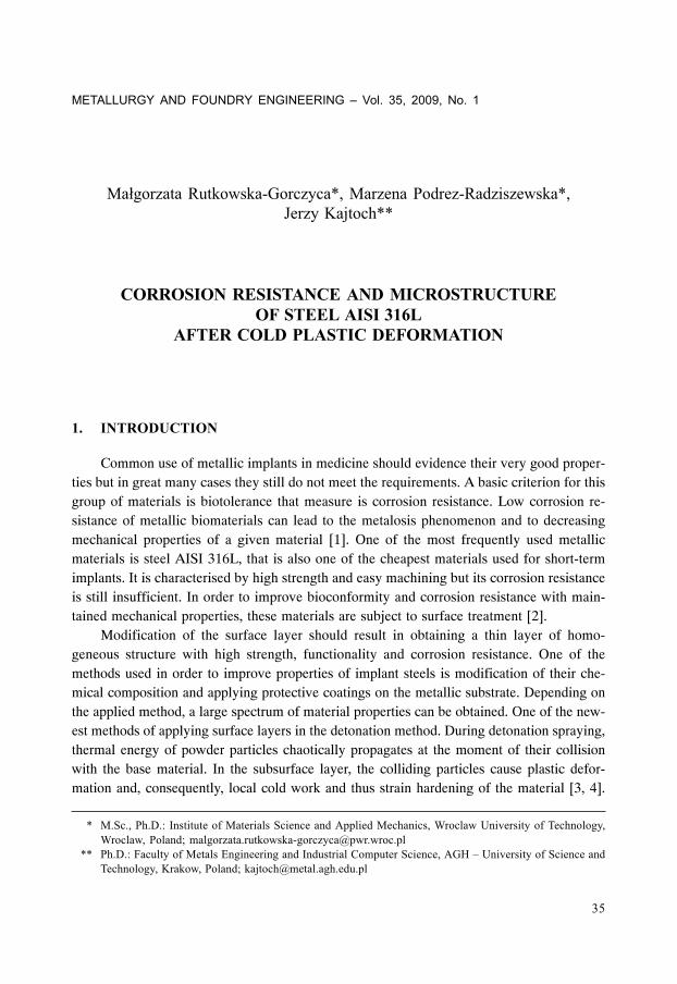
As examined, microstructure of the delivered material was austenitic with numerousrecrystallisation twins, see Figure 1. With respect to chemical composition and level ofimpurities, the steel meets the requirements of PN-ISO 5832-1:1997.
Steel sheets 50 mm wide and 250 mm long were subject to cold rolling to obtain strips0.9 to 0.5 mm thick with the cold working ratios of 10, 20, 30, 40 and 509.
Cold rolling was performed at the Department of Metal Working of AGH University ofScience and Technology in Krakow, on a rolling mill quarto L200 that enabled reversingrolling of thin strips with back tension. Layout of the mill is shown in Figure 2. The teststand permitted recording pressure forces and rotational speed of the roll as well as tensionforces [5].
Because of high flow stress of the examined steel after cold rolling and spring mount-ing of the upper roll, obtaining large plastic deformations in one pass was impossible. Inpractice, the cold working ratio in one pass did not exceed 209 (on non-hardened material)and the ratio declined along with the material hardening degree. As a result, higher coldworking ratios (over 209) could be obtained in several passes only, by pressing down therolls subsequently.
Specimens for potentiodynamic tests were in form of disks dia. 14.7 mm cut-out fromthe sheets subject to cold working. Directly before testing, the specimens were ground andpolished. For stabilizing, each specimen before measurement was immersed for 20 minutesin the Ringer solution. Measurements were taken at 20oC.
Electrochemical direct-current measurements in order to determine corrosion resis-tance consisted in measuring the open circuit potential and recording the relationshipi = f (E) during polarisation tests in a three-electrode measurement system. The system con-sisted of a measuring vessel, potentiostat Atlas 0531 (Elektrochemical Unit and ImpedanceAnalyser) and a computer controller. Two electrodes were used: an austenitic auxiliary oneand a reference one in form of a saturated electrode Ag/AgCl.
The tests were performed in the Ringer solution containing 8.6 g/l of sodium chloride,0.3 g/l of potassium chloride and 0.48 g/l of calcium chloride hexahydrate. Selection of thecorrosive medium was related to application of the examined steel for medical implantsand was aimed at simulating the environment of physiological fluids. After 20 minutes of
�;
staying in the solution, the specimens in the same solution were subject to polarisation inanode direction at the velocity dE/dt = 1 mV/s. Values of current and corrosion potentialwere determined using the Stern method by extrapolation of the Tafel lines for anodic andcathodic sections of the curve i = f (E) within ±40 mV from the measured potential of thecathodic-anodic transition.
Microscopic examination after cold working were performed using a light microscopeNeophot 32 and surfaces of the specimens after corrosion tests were observed using an elec-tron scanning microscope JEOL JSM-5800LV to record the occurred corrosion changes.
�� ����������� �����
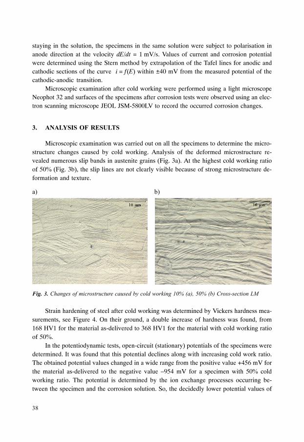
Microscopic examination was carried out on all the specimens to determine the micro-structure changes caused by cold working. Analysis of the deformed microstructure re-vealed numerous slip bands in austenite grains (Fig. 3a). At the highest cold working ratioof 509 (Fig. 3b), the slip lines are not clearly visible because of strong microstructure de-formation and texture.
Strain hardening of steel after cold working was determined by Vickers hardness mea-surements, see Figure 4. On their ground, a double increase of hardness was found, from168 HV1 for the material as-delivered to 368 HV1 for the material with cold working ratioof 509.
In the potentiodynamic tests, open-circuit (stationary) potentials of the specimens weredetermined. It was found that this potential declines along with increasing cold work ratio.The obtained potential values changed in a wide range from the positive value +456 mV forthe material as-delivered to the negative value –954 mV for a specimen with 509 coldworking ratio. The potential is determined by the ion exchange processes occurring be-tween the specimen and the corrosion solution. So, the decidedly lower potential values of
�< =<
�>
the non-polarised specimens should be related to passivation ability of steel in the corrosionmedium, what becomes worse with higher cold deformation degree. The open-circuit po-tential values for the specimens with different cold working ratios are given in Table 2.
�������8���������� �����/��������������
��������?��������� ������������
For the specimens with various cold work ratios, polarisation curves were drawn,showing the relationship between voltage and current density, see Figure 5. Shape of thepolarisation characteristics was similar for all the examined specimens. Similar current den-sities were found in cathodic ranges of the polarisation curves, but clear increase of currentdensity with cold working ratio was observed in anodic ranges. Analysis of the curves indi-cates a clear tendency for decreasing the cathodic-anodic transition potential and increasingthe currents for this potential along with increasing strain hardening. In the course of thecurves, a clear stability loss of the current density is observed, related to the changes occur-ring in the passive material layer. Along with increasing cold working ratio, these changeswere observed at lower and lower potential values. The corrosion potential Ekor and currentIkor values were determined by extrapolation of the Tafel curves, see Table 3.
The corrosion potential value was –38.5 mV for the as-delivered material and declinedto –115.7 mV for the specimen with 50� cold working ratio. Such a potential difference issufficient for corrosion occurrence in the case when some places with differentiated colddeformation degree exist in the material. The corrosion current density increased over12 times from 12 nA/cm2 for the as-delivered material to 148 nA/cm2 for the specimen withmaximum cold working ratio. The measurement results for all the specimens are settled inTable 3.
The results indicate that corrosion resistance of the austenitic steel declines with in-creasing strain hardening degree. Shorter thermodynamic durability of strain-hardened steelincreases probability of corrosion occurrence. This shortened thermodynamic durability isattributed to its increased internal energy. Injured tightness of the passive layer is deter-mined as another cause of worsened corrosion resistance of the steel [6].
Microscopic observations of the specimens after corrosion tests revealed pits on theirsurfaces. It was found that intensity as well as size and depth of the pits is dependent on coldworking ratio of the specimens, see Figure 6. Along with increasing cold working ratio,more and more numerous pits were observed. On the specimen in the as-delivered condi-tion, small, round and not very deep pits were observed on the surface, see Figure 6a. Themost intensive and extensive changes were recorded on the specimen with 509 cold work-ing ratio, see Figure 6d. A number of holes distributed around the pit mouth was observed.Nature of the pits was similar to that of the pits obtained in [7], also in the environmentcontaining Cl– ions. Ernst et al. [8] showed that pit growth in depth follows a parabolic lawwith time and is independent on the potential. The lateral growth is essentially a sequence ofdeterministic undercutting events, each resembling growth of a metastable pit. Growth oflateral pit is linear with time and dependent on the potential.
The research was aimed at evaluating influence of cold working ratio on corrosionresistance of the austenitic steel AISI 316L. To determine the microstructure changes aftercold plastic deformation, metallographic examinations were performed and hardness mea-sured. Microscopic observations revealed changes caused by plastic deformation in form ofnumerous slip bands within austenite grains. With increasing cold working ratio, more andmore numerous slip bands are visible, however at 509 cold working ratio the slip bandsdisappear as a result of strong material deformation.
The research revealed distinct hardness increase of cold-worked steel, from 168 HV1for the as-delivered material to 368 HV1 for the material with the highest cold working ratio.The hardness increase is related to strain hardening caused by cold plastic deformation.
The research revealed also a clear drop of corrosion resistance of the deformed mate-rial. The corrosion tests showed the following changes occurring with increasing coldworking ratio:
This scientific work was financed from the means of Wroclaw University of Technologyby the Development Grant No. 332727/I19 and the Internal Promotion Grant No. 332123.