Installation & operating instructions
Isotherm Cruise & Cruise INOX marine refrigerators
Type: CR 42, CR 49, CR 65, CR 85 & CR 130
Indel Webasto Marine USA, Inc.
3400 Gateway Drive
Unit 107
Pompano Beach, FL 33069
Tel +1 954 984 8448, +1 800 422 9711
Fax +1 954 979 2533
E-mail: [email protected]
www.indelwebastomarineusa.com
Table of contents
1 Introduction
1.1 General
1.2 Safety and precautions
1.3 Environmental markings
2 Operation
2.1 Temperature setting thermostat
2.2 Temperature setting ASU
2.3 User tips
2.4 Defrosting
3 Maintenance
3.1 Battery voltage sensor
4 Installation instructions
4.1 Ventilation
4.2 Door front
4.3 Reverse door swing
4.4 Electrical connections
4.5 Electrical wire gauge
4.6 Inner light
4.7 Wiring diagram
5 Technical data
6 Trouble shooting
7 Installation dimensions
1
1. Introduction1.1 General
Isotherm refrigerators are specially designed to operate
in tough marine environments. They are fi tted with a fully
hermetic, leak-free compressor, they offer the lowest
possible power consumption and noise level. All models
are simple to install. They can withstand an angle of heel
up to 30°, for a short time. To ensure that your Isotherm
fridge operates as effi ciently as possible, please follow
these general guidelines:
• Unnecessary opening of the fridge door will increase
power consumption.
• Good ventilation of the compressor and condenser
unit will reduce power consumption.
• The electrical system should be in good condition.
Inspect batteries and charging levels regularly.
Always use a separate starter battery for the engine.
Follow carefully the guidelines regarding electrical
cable areas and fuse placements.
• Keep the inside of the fridge and freezer clean and
dry. Remove any water from condensation that may
have collected in the drip tray or the plastic basket.
• Keep the door slightly open to air the refrigerator
when leaving the boat for any length of time.
• Clean the inside of the refrigerator with luke warm
water and a mild detergent before taking the fridge
into operation the fi rst time.
The refrigerators are equipped with an evaporator forming
a freezer compartment placed in the top of the cabinet. It
has a door hinged above the evaporator.
The CR 130 Drink has no freezer compartment, the
evaporator is positioned on the rear wall.
The freezer compartment is made to keep pre-frozen
food frozen during a short period of time and not to freeze
food.
CR 49, 65, 85 & 130 are also available in an INOX ver-
sion.
They have a more exclusive door in stainless steel and
they also have a fl ush mounting frame for a smooth fl at
mounting on board. The doors have a stainless steel door
lock of a more rigid type and are also equipped with inte-
rior trims in stainless steel.
For your own and others safety, read this fi rst.
Danger! When connected to mains power, ensure
that the power supply is equipped with an earth
safety automatic switch, a ”ground fault circuit
interrupter”.
Danger! Never touch bare electrical wiring
connected to the AC power supply.
Do not use the device if the connector cables show
visible damage.
Never connect battery charger direct to the
refrigeration system.
A battery charger must be connected to the battery,
never direct to the refrigeration system.
Danger! In addition to acid, a newly-charged battery
contains explosive gas.
Never cover the ventilation openings for the
compressor unit.
Refrigerant may never be let out in the air.
Repair of the refrigeration circuit must be done by a
certifi ed technician.
1.3 Environmental markings
This appliance is marked according to the European
directive 2002/96/EC on Waste Electrical and Electronic
Equipment (WEEE). By ensuring this product is disposed
of correctly, you will help prevent potential negative
consequences for the environment and human health,
which could otherwise be caused by inappropriate waste
handling of this product.
The symbol on the product, or on the documents
accompanying the product, indicates that this product
may not be treated as household waste. Instead it
shall be handed over to the applicable collection point
for recycling of electrical and electronic equipment.
Disposal must be carried out in accordance with local
environmental regulations for waste disposal.
For more detailed information about treatment, recovery
and recycling of this product,
please contact your local city offi ce,
your household waste disposal service
or the shop where you purchased the
product.
1.2 Safety and precautions
2
2. Operation
The refrigerators are available in two versions, standard
with mechanical thermostat and optionally in ASU version.
CR 42 and CR INOX cannot be equipped with ASU.
Temperature regulation for both systems are described
separately below.
The refrigerators are made for use at ambient tempera-
tures between 32°F and 113°F.
2.1 Temperature regulation thermostat
The refrigerator is fi tted with a manually operated
thermostat. This is turned clockwise to reduce
temperature and anti-clockwise to both increase
temperature and activate the on-off switch at the end
position, 0-position. A certain spring resistance is
recognized at the off position.
It is advisable to start with the thermostat in a medium
position. It is advisable to keep a temperature of 41-43°F
inside the refrigerator. Higher temperatures will reduce
storage time.
The ambient temperature infl uences the temperature also
inside the fridge. Avoid direct sunshine and other heat
sources close to the refrigerator.
The thermostat control knob is placed inside the
refrigerator, see description below.
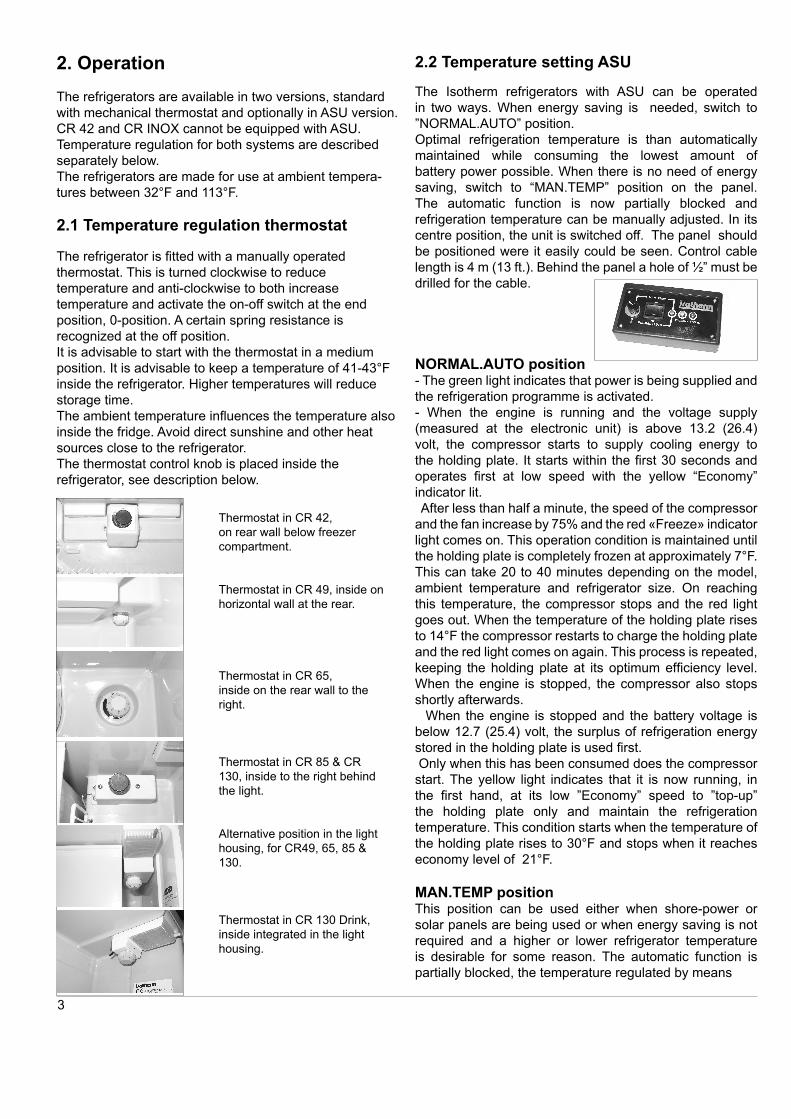
2.2 Temperature setting ASU
The Isotherm refrigerators with ASU can be operated
in two ways. When energy saving is needed, switch to
”NORMAL.AUTO” position.
Optimal refrigeration temperature is than automatically
maintained while consuming the lowest amount of
battery power possible. When there is no need of energy
saving, switch to “MAN.TEMP” position on the panel.
The automatic function is now partially blocked and
refrigeration temperature can be manually adjusted. In its
centre position, the unit is switched off. The panel should
be positioned were it easily could be seen. Control cable
length is 4 m (13 ft.). Behind the panel a hole of ½” must be
drilled for the cable.
NORMAL.AUTO position- The green light indicates that power is being supplied and
the refrigeration programme is activated.
- When the engine is running and the voltage supply
(measured at the electronic unit) is above 13.2 (26.4)
volt, the compressor starts to supply cooling energy to
the holding plate. It starts within the fi rst 30 seconds and
operates fi rst at low speed with the yellow “Economy”
indicator lit.
After less than half a minute, the speed of the compressor
and the fan increase by 75% and the red «Freeze» indicator
light comes on. This operation condition is maintained until
the holding plate is completely frozen at approximately 7°F.
This can take 20 to 40 minutes depending on the model,
ambient temperature and refrigerator size. On reaching
this temperature, the compressor stops and the red light
goes out. When the temperature of the holding plate rises
to 14°F the compressor restarts to charge the holding plate
and the red light comes on again. This process is repeated,
keeping the holding plate at its optimum effi ciency level.
When the engine is stopped, the compressor also stops
shortly afterwards.
When the engine is stopped and the battery voltage is
below 12.7 (25.4) volt, the surplus of refrigeration energy
stored in the holding plate is used fi rst.
Only when this has been consumed does the compressor
start. The yellow light indicates that it is now running, in
the fi rst hand, at its low ”Economy” speed to ”top-up”
the holding plate only and maintain the refrigeration
temperature. This condition starts when the temperature of
the holding plate rises to 30°F and stops when it reaches
economy level of 21°F.
MAN.TEMP positionThis position can be used either when shore-power or
solar panels are being used or when energy saving is not
required and a higher or lower refrigerator temperature
is desirable for some reason. The automatic function is
partially blocked, the temperature regulated by means
Thermostat in CR 42,
on rear wall below freezer
compartment.
Thermostat in CR 49, inside on
horizontal wall at the rear.
Thermostat in CR 65,
inside on the rear wall to the
right.
Thermostat in CR 85 & CR
130, inside to the right behind
the light.
Alternative position in the light
housing, for CR49, 65, 85 &
130.
Thermostat in CR 130 Drink,
inside integrated in the light
housing.
3
of the rheostat on the panel, clockwise for colder and
anticlockwise for warmer. “A” indicates the holding
plate temperature point for “accumulation”. In the
“MAN.TEMP” position, the compressor starts and runs in
the fi rst hand in low speed to maintain the temperature
chosen and keep the noise on lowest possible level. If the
difference between chosen and real temperature is more
than 11°F, the compressor will automatically speed up for
faster cooling down. As soon as this extra power is not
needed, the compressor speed will be reduced for lowest
power consumption and keeping selected temperature.
Indicator lightsGreen:
Power is on, compressor standing.
Green+yellow:
Compressor running within the higher temperature range.
(Low voltage).
Green+red:
Compressor running with the lower temperature range.
(High voltage).
Green+yellow+red:
Compressor running at lowest possible speed to reach
selected temperature in MAN.TEMP mode.
Flashing yellow+red:
Error signal from electronic unit. Automatic start attempt
after 1 min.
Flashing yellow:
Low battery voltage sensor has switched off. Automatic
re-start occurs when engine is started to charge batteries
again.
There is a delay of up to 30 sec. before reactions after
panel operations.
2.3 User tips
- The freezer compartment is meant for short time
storage of pre-frozen food. It has not capacity for
quick or deep freezing.
- Start up the refrigerator if possible 6 hours before it
shall be loaded with food.
- When making ice in the ice tray, place it direct on the
evaporator and put nothing on top of the ice tray.
For quicker ice-making, turn the thermostat to
coldest position.
- Load the food inside the refrigerator in such a way, air
can circulate to equalize the temperature.
- Do not cover the shelves with glass or paper etc.
- To reduce the amount of ice building up in the
evaporator, cover all liquids and moist food.
- Let all hot foods cool well before putting them into the
refrigerator.
2.4 Defrosting
The evaporator is working on below freezing temperatures
and will form frost and ice from humidity in the air. The
humidity increases with higher outside temperature, with
storage of non sealed fresh food and liquids and the time
the door is kept open. Defrosting shall be made when the
frost layer is more than 1/8” thick.
Set the thermostat in OFF position or switch off on the
ASU control panel. Store the foodstuff and the liquid as
cold as possible during the defrosting process.
Do not use sharp metal tools to remove frost or
ice. Do not re-start until the refrigerator is completely
defrosted, cleaned and dried. Empty and clean also the
plastic drip tray below the evaporator. Place towels in the
bottom of the refrigerator to collect melt water.
3. Maintenance
The Isotherm refrigeration systems have a fully
hermetic closed cooling system and do not require any
maintenance or refi lling of refrigerant. The compressor
is of mobile type and has a very high effi ciency and an
outstanding life-time. The refrigerator shall be left in
the boat during the winter. (If the temperature is below
freezing point, the compressor may not start). The
maintenance is reduced to periodically, not less than a
year, cleaning of the condenser from dust. Use a soft
brush and no sharp tools. Keep the cabinet inside clean.
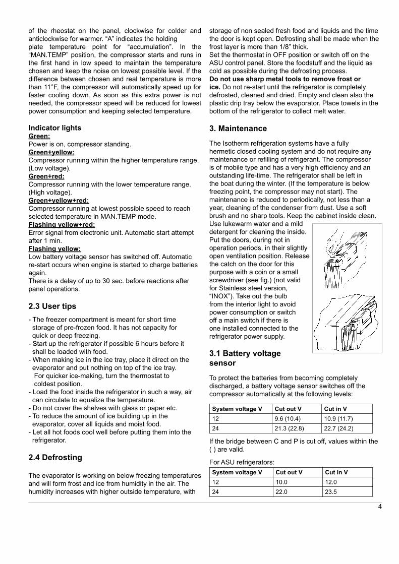
Use lukewarm water and a mild
detergent for cleaning the inside.
Put the doors, during not in
operation periods, in their slightly
open ventilation position. Release
the catch on the door for this
purpose with a coin or a small
screwdriver (see fi g.) (not valid
for Stainless steel version,
“INOX”). Take out the bulb
from the interior light to avoid
power consumption or switch
off a main switch if there is
one installed connected to the
refrigerator power supply.
4
3.1 Battery voltage
sensor
To protect the batteries from becoming completely
discharged, a battery voltage sensor switches off the
compressor automatically at the following levels:
System voltage V Cut out V Cut in V
12 9.6 (10.4) 10.9 (11.7)
24 21.3 (22.8) 22.7 (24.2)
If the bridge between C and P is cut off, values within the
( ) are valid.
For ASU refrigerators:
System voltage V Cut out V Cut in V
12 10.0 12.0
24 22.0 23.5
4 Installation instructions
Many boats have a space which is intended for a fridge.
The Isotherm Cruise fridge has been designed to suit the
general dimensions normally used for this purpose.
The compressor should normally stand upright in the
boat, but will operate at an angle of heel up to 30° and
for short periods even more. CR 42 has the compressor
attached on a separate bracket by its rear side. This can
be moved up to 4.9 ft. away from the fridge.
The pipes must be handled and bent with great care to
avoid damages.
Avoid mounting the refrigerator close to a heat source,
like gas ovens and heaters. Also avoid a position allowing
direct sunshine on the refrigeration unit.
The mounting position should be dry and protected from
splashing water.
For easier mounting of the refrigerator, use the mounting
rails available as optional equipment, on the models not
having three side mounting frame.
The types CR 49 and CR 65 have mounting frame as
standard. CR 42 can be equipped with the same type of
frame as on CR 49. Other models can be mounted with
mounting rails, one on each side of the cabinet.
CR 85 and CR 130 can also be equipped with three side
fl ush mounting frame.
The INOX type refrigerators have a fl ush mounting frame,
three side frame, as standard.
The refrigerators shall be standing on the rubber feet
and locked in position by means of the mounting frame
or mounting rails. When no rails or frames are used the
cabinet must be well fastened into the surrounding con-
structions.
Avoid mounting close to a heat source, like gas oven and
heaters. Also avoid a position allowing direct sunshine on
the refrigerator. The mounting should be dry and protect-
ed from splashing water.
4.1 VentilationIt is very important that the compressor/condenser unit is
well ventilated and that cold air can enter at the bottom,
pass behind the fridge and warm air can leave at the
top in the area where it is mounted. The natural fl ow of
air from below and upwards behind the fridge can be
increased by arranging ventilation openings at the rear.
Make sure there is a free area of 15 - 23 sq.in. below
and behind the refrigerator to allow ventilation air to pass
behind from below. See fi g.
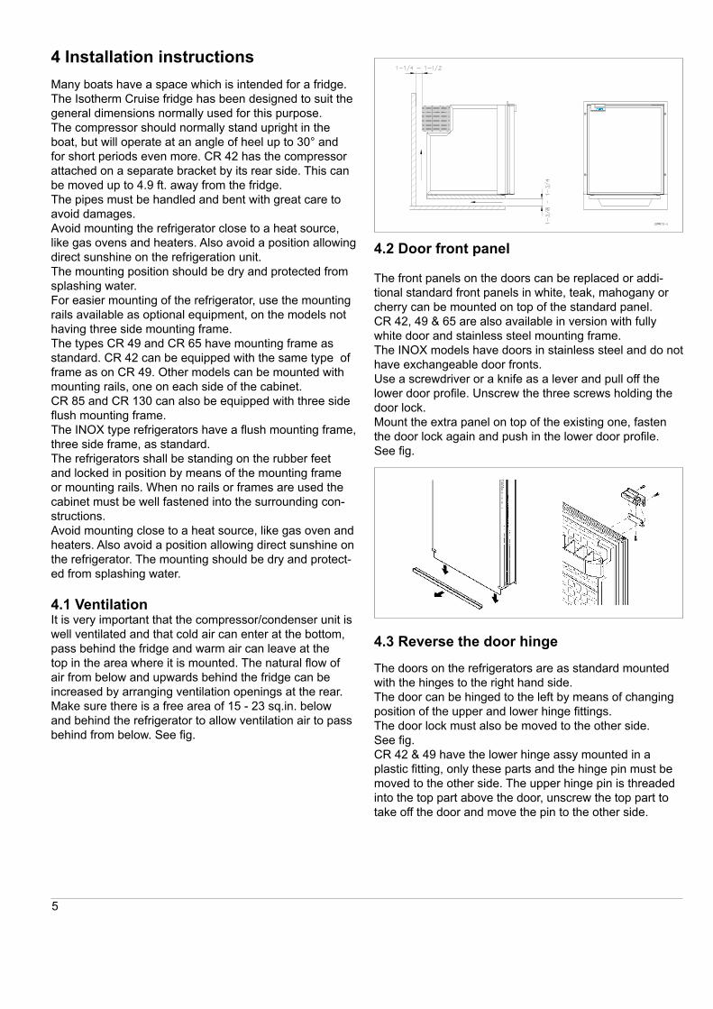
4.2 Door front panel
The front panels on the doors can be replaced or addi-
tional standard front panels in white, teak, mahogany or
cherry can be mounted on top of the standard panel.
CR 42, 49 & 65 are also available in version with fully
white door and stainless steel mounting frame.
The INOX models have doors in stainless steel and do not
have exchangeable door fronts.
Use a screwdriver or a knife as a lever and pull off the
lower door profi le. Unscrew the three screws holding the
door lock.
Mount the extra panel on top of the existing one, fasten
the door lock again and push in the lower door profi le.
See fi g.
5
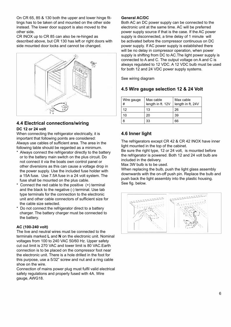
4.3 Reverse the door hinge
The doors on the refrigerators are as standard mounted
with the hinges to the right hand side.
The door can be hinged to the left by means of changing
position of the upper and lower hinge fi ttings.
The door lock must also be moved to the other side.
See fi g.
CR 42 & 49 have the lower hinge assy mounted in a
plastic fi tting, only these parts and the hinge pin must be
moved to the other side. The upper hinge pin is threaded
into the top part above the door, unscrew the top part to
take off the door and move the pin to the other side.
On CR 65, 85 & 130 both the upper and lower hinge fi t-
tings has to be taken of and mounted on the other side
instead. The lower door support is also moved to the
other side.
CR INOX up to CR 85 can also be re-hinged as
described above, but CR 130 has left or right doors with
side mounted door locks and cannot be changed.
4.5 Wire gauge selection 12 & 24 Volt
Wire gauge
#
Max cable
length in ft. 12V
Max cable
length in ft, 24V
12 13 26
10 20 39
8 33 66
4.6 Inner light
The refrigerators except CR 42 & CR 42 INOX have inner
light mounted in the top of the cabinet.
Be sure the right type, 12 or 24 volt, is mounted before
the refrigerator is powered. Both 12 and 24 volt bulb are
included in the delivery.
Max 3W bulb is to be used.
When replacing the bulb, push the light glass assembly
downwards with the on-off push pin. Replace the bulb and
push back the light assembly into the plastic housing.
See fi g. below.
4.4 Electrical connections/wiring
DC 12 or 24 volt
When connecting the refrigerator electrically, it is
important that following points are considered:
Always use cables of suffi cient area. The area in the
following table should be regarded as a minimum.
* Always connect the refrigerator directly to the battery
or to the battery main switch on the plus circuit. Do
not connect it via the boats own control panel or
other diversions as this can cause a voltage drop in
the power supply. Use the included fuse holder with
a 15A fuse. Use 7.5A fuse in a 24 volt system. The
fuse shall be mounted on the plus cable.
* Connect the red cable to the positive (+) terminal
and the black to the negative (-) terminal. Use tab
type terminals for the connection to the electronic
unit and other cable connectors of suffi cient size for
the cable size selected.
* Do not connect the refrigerator direct to a battery
charger. The battery charger must be connected to
the battery.
AC (100-240 volt)
The live and neutral wires must be connected to the
terminals marked L and N on the electronic unit. Nominal
voltages from 100 to 240 VAC 50/60 Hz. Upper safety
cut out limit is 270 VAC and lower limit is 80 VAC.Earth
connection is to be placed on the compressor foot near
the electronic unit. There is a hole drilled in the foot for
this purpose, use a 5/32” screw and nut and a ring cable
shoe on the wire.
Connection of mains power plug must fulfi l valid electrical
safety regulations and properly fused with 4A. Wire
gauge, AWG18.
6
General AC/DC
Both AC an DC power supply can be connected to the
electronic unit at the same time. AC will be preferred
power supply source if that is the case. If the AC power
supply is disconnected, a time delay of 1 minute will
be activated before the compressor continuous on DC
power supply. If AC power supply is established there
will be no delay in compressor operation, when power
supply is shifting from DC to AC.The light power supply is
connected to A and C. The output voltage on A and C is
always regulated to 12 VDC. A 12 VDC bulb must be used
for both 12 and 24 VDC power supply systems.
See wiring diagram
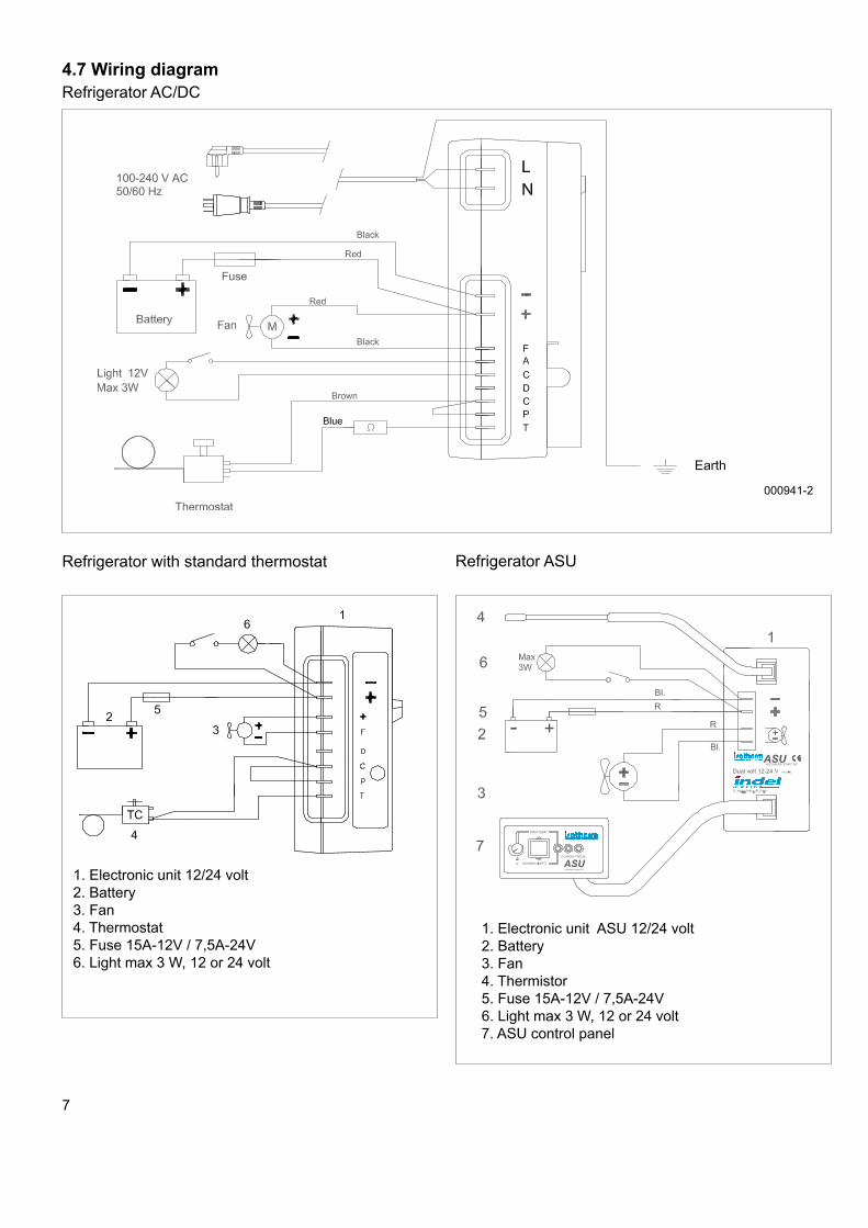
4.7 Wiring diagram
Refrigerator with standard thermostat
1. Electronic unit 12/24 volt
2. Battery
3. Fan
4. Thermostat
5. Fuse 15A-12V / 7,5A-24V
6. Light max 3 W, 12 or 24 volt
Refrigerator ASU
1. Electronic unit ASU 12/24 volt
2. Battery
3. Fan
4. Thermistor
5. Fuse 15A-12V / 7,5A-24V
6. Light max 3 W, 12 or 24 volt
7. ASU control panel
7
000941-2
Refrigerator AC/DC
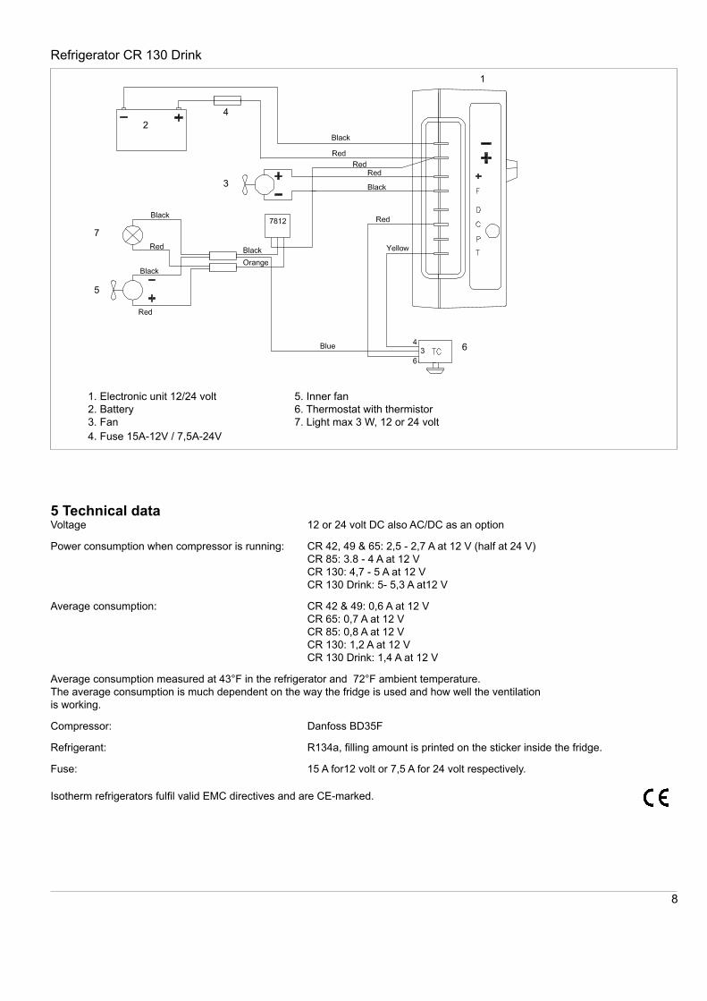
Refrigerator CR 130 Drink
1. Electronic unit 12/24 volt
2. Battery
3. Fan
4. Fuse 15A-12V / 7,5A-24V
5. Inner fan
6. Thermostat with thermistor
7. Light max 3 W, 12 or 24 volt
8
5 Technical dataVoltage 12 or 24 volt DC also AC/DC as an option
Power consumption when compressor is running: CR 42, 49 & 65: 2,5 - 2,7 A at 12 V (half at 24 V)
CR 85: 3.8 - 4 A at 12 V
CR 130: 4,7 - 5 A at 12 V
CR 130 Drink: 5- 5,3 A at12 V
Average consumption: CR 42 & 49: 0,6 A at 12 V
CR 65: 0,7 A at 12 V
CR 85: 0,8 A at 12 V
CR 130: 1,2 A at 12 V
CR 130 Drink: 1,4 A at 12 V
Average consumption measured at 43°F in the refrigerator and 72°F ambient temperature.
The average consumption is much dependent on the way the fridge is used and how well the ventilation
is working.
Compressor: Danfoss BD35F
Refrigerant: R134a, fi lling amount is printed on the sticker inside the fridge.
Fuse: 15 A for12 volt or 7,5 A for 24 volt respectively.
Isotherm refrigerators fulfi l valid EMC directives and are CE-marked.
2
7
5
3
1
4
6
9
7 Installation dimensions
Type Height Width Depth
CR 42 20-3/4 15 18-3/4 (12-1/2)
CR 42 INOX 20-7/8 15-3/4 20-5/16 (14-15/16)
CR 49 20-3/4 15 18-1/2
CR 49 INOX 20-7/8 15-3/4 20-5/16
CR 65 20-7/8 17-3/4 20-3/8
CR 65 INOX 20-3/4 18-7/16 21-3/16
CR 85 24-5/8 18-3/4 20-1/4
CR 85 INOX 24-3/8 19-1/2 21-3/4
CR 130/CR 130 Drink 29-5/8 20-3/4 19-7/8
CR 130 INOX/
CR 130 Drink INOX
29-5/16 21-7/16 21-3/8
Please notice! Refrigerators with AC/DC electronic unit have a depth of 3/4” more than in the table above.
Dimension drawings can be seen on www.indelmarineusa.com
080515-LLG
CRman-us08.ind
6 Fault fi nding
Fault Possible cause Action
Fridge not cold, compressor will
not start.
No power supply.
Battery in poor condition.
Faulty thermostat.
Faulty electronic unit.
Check that power is present at electronic unit.
Check fuse.
Check polarity on connectors and cables.
Bridge the thermostat over T-C, see wiring diagram.
If compressor starts, this indicates a faulty thermo-
stat. If the compressor does not start, this indicates a
faulty electronic unit or compressor.
Contact an authorized service agent.
A possible leak in the cooling system, contact an
authorized service agent.
Compressor makes only short
start attempts.
Bad power supply, too low voltage or
voltage drop at start attempts.
Discharged batteries.
Check cables, terminals and other connections, pos-
sible verdigris or corrosion, Clean.
Charge batteries, run the engine or connect a battery
charger. Voltage must be kept above 11.0 V at start
attempts.
Compressor runs but no refrig-
eration generated.
Loss of refrigerant. Leakage in pipes or
evaporator.
Pipes blocked.
Pressure and leak test. Check for pipe damages.
Repair possible leak, evacuate and re-fi ll refrigerant.
(All this to be made by refrigeration specialist).
Compressor runs long time but
not generating enough cold.
Bad ventilation. Condenser too warm.
Cooling fan not working
Too much frost on evaporator.
Door not closing well.
Condenser blocked by dust.
Improve ventilation for compressor.
Re-place fan.
Defrost.
Check/adjust door position and door seal.
Clean condenser.
Fuse blows. Wrong fuse size.
Faulty electronic unit.
Check fuse, 15 A-12 V / 7,5 A-24 V
Exchange electronic unit.
If a complicated fault does occur, such as reqouiring specialist assistance, please contact Indel Marine USA,
Inc or your local marine distributor for advice.


![Index [musclecar-parts.com]musclecar-parts.com/MoparCatalogs/goodmark mopar.pdf · Parts marked with this symbol are officially licensed products of Chrysler LLC. High performance](https://static.documents.pub/doc/80x56/5a9d95747f8b9a28388bf776/index-musclecar-partscommusclecar-partscommoparcatalogsgoodmark-moparpdfparts.jpg)


