This content has been downloaded from IOPscience. Please scroll down to see the full text. Download details: IP Address: 18.101.24.111 This content was downloaded on 01/07/2014 at 19:39 Please note that terms and conditions apply. Crack tip fields in a material with three independent slip systems: NiAl single crystal View the table of contents for this issue, or go to the journal homepage for more 1992 Modelling Simul. Mater. Sci. Eng. 1 53 (http://iopscience.iop.org/0965-0393/1/1/006) Home Search Collections Journals About Contact us My IOPscience
Transcript
This content has been downloaded from IOPscience. Please scroll down to see the full text.
Download details:
IP Address: 18.101.24.111
This content was downloaded on 01/07/2014 at 19:39
Please note that terms and conditions apply.
Crack tip fields in a material with three independent slip systems: NiAl single crystal
View the table of contents for this issue, or go to the journal homepage for more
1992 Modelling Simul. Mater. Sci. Eng. 1 53
(http://iopscience.iop.org/0965-0393/1/1/006)
Home Search Collections Journals About Contact us My IOPscience
Modelling Simul. Mater. Sci. Eng. 1 (1992) 53-71, Printed in the UK
Crack tip fields in a material with three independent slip systems: NiAl single crystal
Maryam Saeedvafai and James R Rice Division of Applied Sciences, Hamrd University, Cambridge, MA 02138, USA
Received 4 April 1992
Abstraei The crack tip stress and deformation field is analyzed for an ideally plastic ordered NiAl single crysral of B2 (Bcc type) structure which has only three independent slip systems at m m temperature, the {ll0}(lOO) systems. For the crack on the (010) plane growing in the [ l O l ) direction, only one of these systems is capable of sustaining considerable plane plastic Row. It involves slip plan- lying parallel to the crack tip, making an angle of 90' with the crack plane. and has the yield condition ul2 = f r o (1 is the cracking direction, 2 the crack plane normal, and ro the critical resolved shear stress). An elastic-ideally plastic asymptotic solution is derived in which the stress field has a In r type singularity, with a shearing discontinuity at 90'. These features are verified and more fully quantified by a finite element solution. At regions very near the tip, the field is divided into 5 angular sectors of which 2 are plastic regions (a12 = *TO),
one inclined ahead of the crack front and one behind. Further away from the tip, at distances greater than about 0.01 of the overall plastic zone size, the plastic region ahead of the crack front, in which u12 = 70, disappears resulting in 3 angular sectors of which one is plastic, which persists for the rest of the plastic region. While the plastic zone coven a broad angular range, Lhe deformation field within it is dominated by the shear discontinuity of displacement.
The stress on other possible systems such as {110)(111), which in NiAl becomes activated at higher temperalures, and on {112}(111) systems, which are the usual twinning systems for BCC crystals, is also investigated. The results show thal Zones over which the resolved shear stresses on these two set of systems become of the order of critical resolved shear stress on the soft { l l O ) ( l O O ) system are either much smaller than, or of the same order as, the plastic zone for the {llO)(IOO) system, although very close to the crack tip the stresses on some of these systems become significant due to the stress singularity. Thus. wen though the shear strength is much larger for these two systems than for the {llO}(lOO) syslem, over regions extremely near the tip they may become activated and alleviate the stress singularity. It is also possible that cleavage will occur first at lower temperatures or higher strain rates, and such is consistent with the brittleness of NiAL
1. Introduction
Intermetallic ordered alloys have received much attention recently due to their high strength, high melting point, low density and environmental stability. Of these, B2 structured (BCC type) NiAl has limited room temperature ductility, which reduces its range of application. The {llO}(laO) systems are the active slip systems for NiAl single crystals at room temperature as found by various researchers (Vedula
t e-mail: maryam Q b e t a . l d . g o v
54
and Stephens 1987, Vedula et a1 1989, Guha et a1 1989, Fu and Yo0 1991, Miracle et a1 1989, George and Liu 1991, Russell er a1 1989). These constitute only three independent systems, which are in general insuficient to fully alleviate the crack tip stress singularity, since a minimum of five systems are required to accommodate an arbitrary strain field. At higher temperatures (above 800 K at normal laboratory strain rates, of the order of s-l) or with the addition of other solutes such as Cr and Mn (Miracle er al 1989), the {110)(111) system also becomes active, hut due to the high APB energy of dissociation of the (111) superdislocation into partials (see Fu and Yo0 1991), very little activity is observed on this system at lower temperaturcs. Since the ideal cleavage strength of NiAl single crystals is not particularly low (about 29 GPa on the (001) plane as calculated by Fu and Yo0 (1991) using electron density functional methods), the usual brittleness of these crystals is generally thought to be the result of an insufficient number of slip systems at room temperature.
In this paper the crack tip field in NiAl single crystals, with the crack on the (001) cleavage plane, is studied in an attempt to investigate the crack tip deformation mechanisms resulting when there is an insufficient number of slip systems. The results could describe any solid which can flow plastically only, or primarily, in response to shear stress u12, where direction 1 is the direction of crack growth and direction 2 is perpendicular to the crack plane. A simple elastic-ideally plastic single crystal material model is adopted, and is implemented within 'small geometry change' assumptions by both asymptotic and finite element analysis to determine the incompletely relaxed crack tip stress and deformation field.
M Saeedvafa and J R Rice
2. Finite element formulation
A 'User Material' subroutine was written by Huang (1991) for use in the finite element code ABAQUS (1989) to incorporate single crystal plasticity laws. The following is a summary of the constitutive laws used in the options within this subroutine that are appropriate to the present 'small strain' analysis.
Total strain rate can be written as the sum of the elastic and plastic strain rates
e . . $1 = i?. : I + i?.. '1 (1)
The plastic strain rate can be described as the tensorial sum of the slip rates on all systems
where i." is the slip rate on system Q and ppj is the Schmid factor. That is
(3) " - 1 a! n pLij - *(Si nj + spnp,
in which ss is the slip direction and ns is normal to slip plane a. The resolved shear stress on system CY is
(4) T " = a . . 0 t,lL,, .
Crack tip jields: NiAl single crystal 55
The stress rate is related to the elastic strain rate by way of
6.. I1 = L;jkrG;r = L i j k l ( t k l - i',,) (5)
where L i j k l is the elastic moduli tensor, taken as isotropic in what follows.
to describe the relation between rate of slip stress T* on that system, namely
A slightly rate-dependent formulation used by Peirce et a1 (1983) has been adopted on a system and the resolved shear
?a = i.u"sgn(Ta) I T " / T ; ~ ' " . (6)
Here 4; and 70" are constants and m -t 00 denotes the rate independent limit, in which 7; could be interpreted as the critical resolved shear stress on the slip system a (m = 100 has been used in this calculation). This rate-dependent formulation eliminates problem with uniqueness, especially in the ideally plastic case for crystals. An implicit time integration proposed by Kanchi et a1 (1978) has been utilized in order to increase the extremely small time steps that would be required by explicit time integration. In this scheme the increment in slip accumulated during the interval At is estimated as
AY = [ (I - e1i.p + si.p+,,] At (7)
and 8 = 0.7 has been used since this value yielded the most accurate results (see Kanchi et a1 (1978)). Furthermore, has been expanded in a one-term 'bylor series to linearize the incremental equations namely
The incremental constitutive relation, from which the tangent stiffness matrix is constructed, is derived by substituting equation (2) into (9, integrating over the time step, and using the results with equations (4), (7) and (8) to eliminate A y a , and has the form
where
Also, from equation (6). [8Ya/d~*], = [i."/mrall has been used in (9). The total strain increment, Ackl , accumulated at an interval At is related to the increment of nodal displacements, A q , in the finite element formulation through a matrix which is the derivative of the element shape, or displacement interpolation, matrix.
The loading range is assumed to be restricted such that the size of the plastic zone is always much smaller than the region over which the conventional crack tip r-'/' elastic singularity dominates, so that small scale yielding conditions are established.
56 M Saeedvafa and J R Rice
The problem could then be modeled as a semi-infinite crack in an infinite body. Here, it is modeled as a crack along a ray of a circular region of radius much larger than the size of any plastic zone developed in the solution. Due to symmetry, only the upper half domain is considered, with points constrained against opening displacements over the plane ahead of the crack. A semi-circular mesh consisting of four noded isoparametric elements is used, where the inner nodes of the first ring of elements adjacent to the crack tip all occupy the same initial position at the tip. The mesh (shown in figure 1) is divided into three zones and at the circular borders between them the angular range of elements is doubled with respect to the inner adjacent zone. Except for the very inner rings which have equal dimensions in the radial direction, the elements have an aspect ratio of 1. The mesh has 6959 nodes and 6768 elements. Mode I tractions are imposed on the outer elements with the mode I stress intensity factor, Kf, as the loading parameter. The stress intensity factor is increased at a uniform rate gl. If T is the total time for the stress intensity factor to increase to the value at which the solution is examined and r,, is the yield stress entering the yield criterion U - &rU to be discussed, then it is possible to see from dimensional analysis that if ‘time 1s denoted by t / T , ‘stress’ by uii/ru, ‘strain’ by eii / ( r u / p ) and ‘displacements’ by p u i / r U , then only three dimensionless parameters enter the formulation. These are the Poisson ratio U, taken to be 0.3, the exponent m, taken to be 100, and the combination + , , T / ( T ~ / ~ ) , taken as 1 in this analysis. The ratio r U / p does not otherwise enter because of the ‘small strain’ framework It would enter a ‘finite strain‘ analysis as a fourth dimensionless material parameter. The choice for +“T/ ( r , , / p ) assures that negligible plastic strain will occur unless r is driven towards, and slightly above, T, (but only slightly; the large m assures, for example, that a T which is 1% above rU produces a strain rate of 3’{,, 5% above produces 13@y,,, and 10% produces 14 x lo3+”). To assure that the stresses, strains and displacements output by the program are U ; ~ / T ~ , e ; i / ( r U / p ) and pu; / ru , each of rU, p and the loading time within the program are specified as unity, this being allowed for p only because a ‘small strain‘ analysis is done. Lengths such as pu i / ru and distance T from the tip are later normalized by ( K1/rU)* in presenting the results, where IC, is the maximum stress intensity factor for this calculation. A nominal size scale for the plastic zone can be obtained by setting r to the value at which uI2 of the elastic singular field reaches -rU along a line in the 2 direction passing the crack tip, giving a nominal radius of K,?/167rr,2 0.02(K1/r0)2. In the mathematical small scale yielding problem for a half-infinite crack in a full space, this is the only length dimension. In the finite element model there are lengths set by element size. and by overall grid dimensions. The ratio of the second to the first is large here (23 x IO3 for the smallest elements at the crack tip); here, it is attempted to make the first irrelevant by growing the plastic region large compared to it, and the second by keeping the plastic zone small compared to it.
‘2 -, .
3. Asymptotic solution
The crystal orientation considered is shown in figure 2(a), with the crack on the (010) plane with its tip along the [Toll direction so as to intersect a slip plane. Figure 2(b) shows the projection of the crystal in the ( i O l ) plane. Only the top half of the crystal is shown due to symmetry. ?faces of the { l l O ) planes of the potentially active slip systems are shown in figure 2(b). Systems capable of large plastic flow under plane
Crack t@ fie&: NiAl single crystal 57
Figure 1. Finite element mesh.
Figure 2. ( a ) Crystal onenlalion. ( b ) Projection of the crack configuration an lhe (iOl) plane. 'Races of the { l l O ) slip planes are marked.
strain conditions must have pL33 = 0. The slip system (lOl)[OlO] is the only one which does (except for the (lOi)[OlO] system which has pll = pZ2 = pI2 = pP3 = 0 and hence no shear stress resolved onto it by tensile loading). The yield surface, which is normally constructed by the inner envelope of all the lines of critical Shear (resolved shear stress on a system, T* = T,), is an unbounded surface, uI2 = +T,, since all the Schmid factors are equal to zero except for plz for this system. Thus the only way that the elastic singularity can be (partially) alleviated is by plastic shearing on the (101)[010] system. Noting the features of a solution to the case of discontinuous shearing on an elastic half plane, as well as by looking at the finite element results discussed later, the crack tip field was assumed to have a logarithmic singularity. The field was assumed to be divided into angular sectors alternating between plastic and elastic regions.
In any plastic regions the shear stress uI2 = fr,, thus the equilibrium equations (oj j ,j = 0, where the third subscript, j , indicates the term is a partial derivative with respect to z j , i.e. ( ) , j = a( ) / a z j ) result in cI1 = cll(zZ) and uz2 = uzz( q). Assuming that the field has a logarithmic singularity then
ul l= ZIInlzzl+Y, uZ2= Zzlnlzll+Y, (11)
58
where Z,, Z,, Y, and Y, are constants. Now since the normal components of the plastic strain, cyl = c e = ci3 = 0, these strain components are entirely elastic and thus for plain strain as assumed here
M Saeedvafa and J R Rice
= 0)
where v is the Poisson ratio and p is the shear modulus. Integrating the first two of the above equations leads to
2PU, = ~ 1 - ~ ~ ~ l l x l - ~ J b Z 2 ~ x l ~ ~ ~ l + f ~ ~ 2 ~ (13)
2pu2 = (1 - ~ ) ~ z z + z - v /o l l (xz )d r , t d x d .
Again since it is assumzed that the field has a logarithmic singularity, f and g in the above equation are assumed to have the form
f ' ( 4 = v, In 1x21 t U, d ( x 1 ) = v, In lZ l l t U2 (14)
where a prime indicates the derivative of the function with respect to its argument and VI, 15, U, and U2 are constants. Thus the full equations for the displacements are
2pu1 = [ ( l - v )Z ,x , + V,x,] In1x21- vZzx , In lxll
2pu2 = [ ( l - v ) Z 2 x 2 t V,x , ] lnIxlI - v Z l x 2 In1q.I (15)
+ qI(1- - vu, t vZ2l t Z,(UI - VI) + w, + x2[(1- Y)Yz - vu, + VZ,] t x , ( U 2 - Kc) + ry,
where W1 and IV, are integration constants. By differentiating the above equations the shear strain is obtained as
4pcl, = 127, + 4 4 = VI In 1x21 + In lxll (16)
i- (1 - v) [Zd~ , /xz ) + z2(~2/xI) l+ U, t 4 ' 2 .
The solution in the elastic regions is derived by using Muskhelishvili complex potentials which are
(Cl1 -t 4 / 2 = Re[24'(z)I ("22 - "1,)/2 + io12 = ( Z - .)4"(.) - 4 ' ( z ) t W.) 2p(u1 f iu2) = (3 - 4v)4(z) + ( 5 - .)$(z)' - n ( z )
- - (17)
where z = x + ix, and the overbar denotes the complex conjugate of the function, and i = h. Again due to the logarithmic singularity, it is assumed that 4' = A In z t B and 0' = C In z f D, where A, B, C and D are complex
Crack tip fields: NiAl single crystal 59
constants (e.g., A = A, + iA,). The full equation of the field derived by using this assumed form of the complex potentials is
2pu1 = [ ( 3 - 4v)A, - C,] cos 8 T In r - [(S - 4v)A2 - C,] sin 8 T In r + [C, - ( 5 - 4v)A1]rB sin I3 + [C, - ( 3 - 4 v ) A Z ] ~ S cos 8 + [ ( 3 - 4 v ) ( ~ , - A , ) + c, - D , I ~ cos e - [ ( 5 - 4 v ) B Z - (3 -4v )Az - D, + C,]T sin 0 + E,
2puz = [(l - 4v)A, + C,] sin 0 T In T + [ ( 3 - 4v)A, + C,] cos 0 T In r + [ ( 3 - 4 v ) ~ , + c,jTe COS e - [(I - 4 v ) ~ z + c,lTe sin e
+ [ ( 3 - ~ v ) ( B , - A*) + D, - c,]. COS e + (18)
+ [( 1 - 4u)B1 - ( 3 - 4u)A, + D, - C,]T sin 0
U,, = (3A, - C,) In r + (C, - 3A2)0 + A,(1 - cos 20) - A, sin 28 + 3B, - D, ~ 2 2 = ( A , + Cx) In T - (Cz + A,)f7- Al ( l -cos 28) + A , sin 20 + B, + D, u ~ ~ = ( C ~ - A Z ) I ~ ~ + ( C 1 - A 1 ) @ - A , ( l - c o ~ 2 8 ) - A ~ ~ i n 2 0 + D , - B ~
where E, and E, are integration constants and z = T exp(i0).
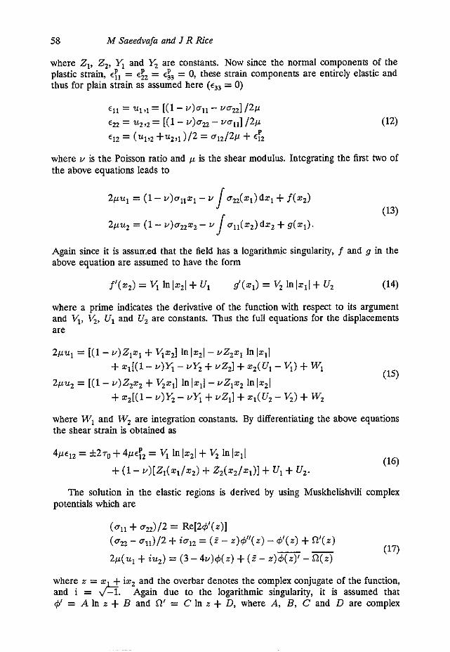
2, IOIOI
Figure 3. Sector arrangement in the asymptotic solution. The shaded regions are plastic Sectors with region [2] at on = + r ~ and region [4] at viz = - Q
The finite element results suggest that very near the crack tip the field is divided into five angular sectors as shown in figure 3, where sectors [2] and [4] are plastic with ul2 = +T,, in sector [2] and U,, = -7" in sector 141. Rice (1987) has proved that the only way a discontinuity can occur for ideally plastic single crystals is either along the direction of, or perpendicular to, the slip plane traces, and thus except for B = 90' where a shear discontinuity can occur (across the slip system trace in the xl- z, plane), full continuity conditions must hold. That is, the stress and displacements are continuous at 0 = e,, 0 = 0, and 0 = 04. At 0 = 90°, U,,, U,, and U, must be continuous but U, and U= need not be. On the crack faces uz2 = U,, = 0 (free surface boundary condition), and ahead of the crack (0 = 0) U,, = uz = 0 due to symmetry. The full field equations in each of the sectors, which are derived by applying these boundary conditions, are given in the appendix. In those expressions the field in every sector is expressed in terms of the set of nine constants Z,, Z,, W,, W,, X, Y, and e,, Oz, 0, which appear in these equations. These constants coincide with some of the constants of the same label, introduced earlier, in specific sections;
60
X and Y redefine constants A, and B, from sector [l]. In addition, the continuity conditions also yield the following relationships between Z,, Z,, O,, 0, and 0,
M Saeedvafa and J R Rice
$ ( z l - z,)0, t i(z, t z,) sin 2 4 = -To i(z, - Z , ) ( K / ~ - e,) - $(z, t z,) sin 28, = 27, +z,(T - e,) - $z, sin 20, = -T" Z,(cot 0, - cot e,) t Z,(tan 8, - tan e,) = 0.
(19) (20)
(21) (22)
As can be seen, the field is not fully determined in the asymptotic solution but five constants are left undetermined, namely e,, W!, W,, X and Y . These can be found by matching the solution with the finite element results.
4. Results of the finite element analysis
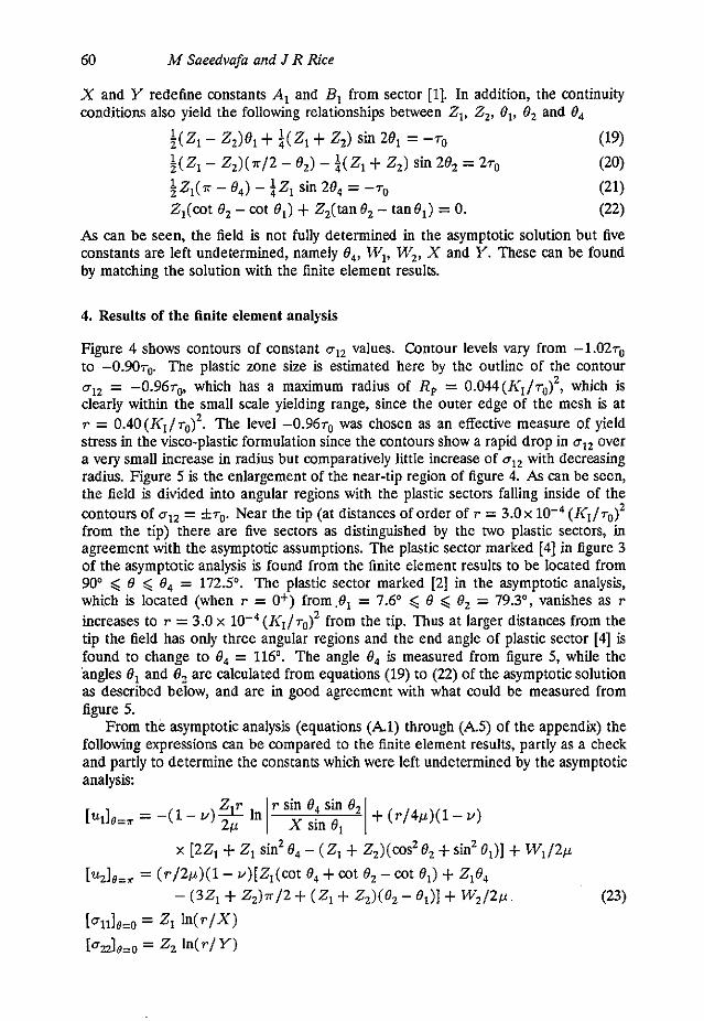
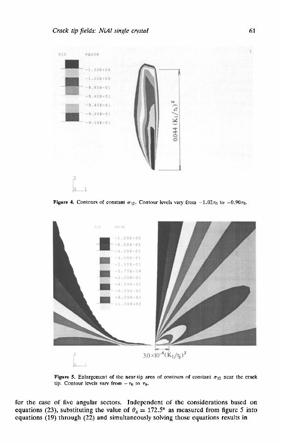
Figure 4 shows contours of constant uI2 values. Contour levels vary from -1.02ro to - 0 . 9 0 ~ ~ The plastic zone size is estimated here by the outline of the contour U,, = -0.96~,, which has a maximum radius of R, = 0.044(IC,/7,)2, which is clearly within the small scale yielding range, since the outer edge of the mesh is at r = 0.40(Kl/r,)'. The level -0 .96~" was chosen as an effective measure of yield stress in the visco-plastic formulation since the contours show a rapid drop in CT,, over a very small increase in radius but comparatively little increase of U,, with decreasing radius. Figure 5 is the enlargement of the near-tip region of figure 4. As can be sccn, the field is divided into angular regions with the plastic sectors falling inside of the contours of U,, = fro. Near the tip (at distances of order of r = 3 . 0 ~ lo-" ( I<, /T")~ from the tip) there are five sectors as distinguished by the two plastic sectors, in agreement with the asymptotic assumptions. The plastic sector marked [4] in figure 3 of the asymptotic analysis is found from the finite element results to be located from 90° 6 0 < 0, = 1 7 2 3 . The plastic sector marked 12.1 in the asymptotic analysis, which is located (when r = O+) from,@, = 7.6O < 0 < 0, = 79.3O, vanishes as r increases to T = 3.0 x 10⁻⁴(Ifl/~,)2 from the tip. Thus at larger distances from the tip the field has only three angular regions and the end angle of plastic sector [4] is found to change to 0, = 116O. The angle 8, is measured from figure 5, while the 'angles 0, and 02 are calculated from equations (19) to (22) of the asymptotic solution as described below, and are in good agreement with what could be measured from figure 5.
From the asymptotic analysis (equations ( k l ) through (AS) of the appendix) the following expressions can be compared to the finite element results, partly as a check and partly to determine the constants which were left undetermined by the asymptotic analysis:
Crack r i p fields: NiA1 single c y t a l 61
Figure 4. Contours of con~tant q z . Contour levels vary Crom -1.0270 lo - 0 . 9 0 ~ 0 .
Figure 5. Enlargement of the near-tip area of contours of constant 012 near the crack tip. Contour levels vary from - q to q,.
for the case of five angular sectors. Independent of the considerations based on equations (23), substituting the value of O4 = 172.5' as measured from figure 5 into equations (19) through (22) and simultaneously solving those equations results in
As described earlier, at distances greater than r == 3.0 x 10⁻⁴(K,/~,)2 from the crack tip the plastic zone ahead of the crack vanishes, resulting in only three angular sectors. The solution for this three-sector field can be obtained from the asymptotic analysis by letting 0, = 8, (which will drop all dependence on 8, or 0, out of rhe equations). Then the field equations for plastic sector [2] become immaterial, and the resulting field equations for elastic sectors 111 and 131 become identical. Substituting 8, = 116.0° (as measured from 6gure 5) into equation (21) leads to
Z, = -1.327, Z, = -2.60~" (25)
for the case of three angular sectors, where the constant Z, was obtained by adding equations (19) and (20) to obtain (2, - Z2)7r/4 = r,.
30 t
0 m I/ 20\
d
I .
Figure 6. Variation of 011 ahead of the crack with distance from the tip.
Figure 8. Variation of oll ahead of the crack with distance fmm the rip on a logarithmic scale.
c Elastic ,. 10
\ 8 -i_L 0 I.OZ aw 0.111 0.08 0.1
R / ( K , / ~ ~
Figure 7. Variation of U= ahead ol rhe crack with distance from the tip.
EQure 9. Variation of a2 ahead df the crack with disunce from the lip on a lo~arifirmic scale.
Crack tip fields: N I X single crystal 63
ahead of the crack with distance from the tip. The dashed lines are the mode I elastic distribution of stresses ahead of the crack, U,, = oz2 = K1/&. Figures 8 and 9 are the same two figures on a logarithmic scale. The solid l i e s are the FEM results, the dashed lines are the results from the five angular sectors of the asymptotic solution, equations (23), and the dot-dashed lines are from the results of three angular sectors, based on Z, and Z, values given above. By positioning the dashed and dotdashed lines to best coincide with the FEM results in different ranges, it is additionally determined that
Figures 6 and 7 show the variation of normal stresses U,, and
x = 9.45 x 1 0 - ~ ( 1 ~ ~ / ~ ~ ) ~
X = 0.06S5(K,/ru)2 Y = 0.0371(K1/~0)2 (27)
Y = 7.75 x 1 0 - ~ ( 1 ~ , / ~ ~ ) ~ (26)
for the case of five angular sectors and
for the case of three angular sectors.
Figure 10. Variation of U, on the crack surface vnth distance from the tip.
Figure 11. Variation of uz on the crack surface with distance from the tip.
Figures 10 and 11 show the variations of the displacements U, and u2 on the crack surface with distance from the tip. Again the solid lines are the FEM results, the dashed lines the results for five angular sectors and dot-dashed lines are the results for three angular sectors of the asymptotic solution. From these figures
W, = -1.48 x W3( I i I )2 /~u 6,, = W2/p = 4.44 x lo-'( l i , ) z / p ~ O (28)
for the case of five angular sectors, where 6,, is the crack opening displacement ( ~ 5 , ~ = [2u2],=, as P - 0), and
w, = 2.00 x lcI)z/ru btiP = w ~ / ~ = 9.72 io-z( K ~ ) ~ / ~ ~ ~ (29)
for the case of three angular sectors. As obvious from these figures, specially figures 5, 8 and 11, the field is clearly
divided into two zones with different slopes in each as caused by the existence of the plastic sector [21 of small radial extent. For both the 3 and 5 angular sectors
64
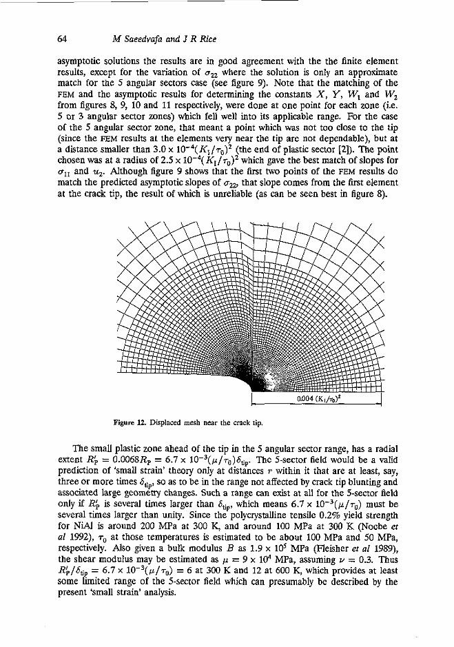
asymptotic solutions the results are in good agreement with the the finite element results, except for the variation of uzz where the solution is only an approximate match for the 5 angular sectors case (see figure 9). Note that the matching of the FEM and the asymptotic results for determining the constants X , Y, W, and W, from figures 8, 9, 10 and 11 respectively, were done at one point for each zone (i.e. 5 or 3 angular sector zones) which fell well into its applicable range. For the case of the 5 angular sector zone, that meant a point which was not too close to the tip (since the FEM results at the elements very near the tip arc not dependable), but at a distance smaller than 3.0 x 10⁻⁴(I(1/~a)z (the end of plastic sector [2]). The point chosen was at a radius of 2.5 x I < I / ~ o ) 2 which gave the best match of slopes for oI1 and uz. Although figure 9 shows that the first two points of the FEM results do match the predicted asymptotic slopes of aZu that slope comes from the first element at the crack tip, the result of which is unreliable (as can be seen best in figure 8).
M Sneedvafa and J R Rice
Figure 12. Displaced mesh near the crack tip
The small plastic zone ahead of the tip in the 5 angular sector range, has a radial extent Rf, = 0.0068R, = 6.7 x 10⁻³(p/7u)6tir The 5-sector field would be a valid prediction of ‘small strain’ theory only at distances T within it that are at least, say, three or more times Stip, so as to be in the range not affected by crack tip blunting and associated large geomeay changes. Such a range can exist at all for the 5-sector field only if R; is several times larger than 6,,, which means 6.7 x 10⁻³(p/~u) must be several times larger than unity. Since the polycrystalline tensile 0.2% yield strength for NiAl is around 200 MPa at 300 K, and around 100 MPa at 300 K (Nocbe et a1 1992), at those temperatures is estimated to be about 100 MPa and 50 MPa, respectively. Also given a bulk modulus B as 1.9 x l@ MPa (Fleisher ef a1 1989), the shear modulus may be estimated as p = 9 x lo4 MPa, assuming Y = 0.3. Thus I?;/&, = 6.7 x 10⁻³ (p /~u) = 6 at 300 K and 12 at 600 K, which provides at least some limited range of the 5-sector field which can presumably be described by the present ‘small strain’ analysis.
Crack tip fields: NiAl single crystal 65
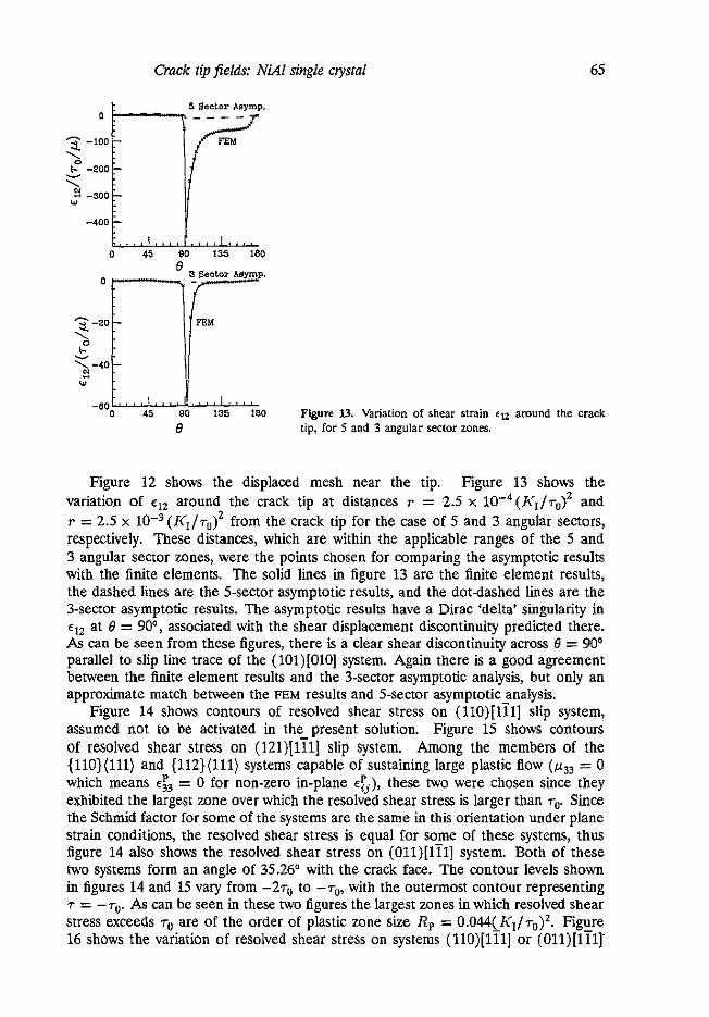
-BO o 45 80 135 180 Figure 13. Variation of shear strain €12 amund the crack e tip, for 5 and 3 angular sector zones.
Figure 12 shows the displaced mesh near the tip. Figure 13 shows the variation of eI2 around the crack tip at distances r = 2.5 x 10⁻⁴(K,/r0)2 and T = 2.5 x (I<I/ru)z from the crack tip for the case of 5 and 3 angular sectors, respectively. These distances, which are within the applicable ranges of the 5 and 3 angular sector zones, were the points chosen for comparing the asymptotic results with the finite elements. The solid lines in figure 13 are the finite element results, the dashed lines are the 5-sector asymptotic results, and the dotdashed l i e s are the 3-sector asymptotic results. The asymptotic results have a Dirac 'delta' singularity in q2 at I3 = 90°, associated with the shear displacement discontinuity predicted there. As can be seen from these figures, there is a clear shear discontinuity across I3 = 90° parallel to slip line trace of the (101)[010] system. Again there is a good agreement between the finite element results and the 3-sector asymptotic analysis, but only an approximate match between the FEM results and 5-sector asymptotic analysis.
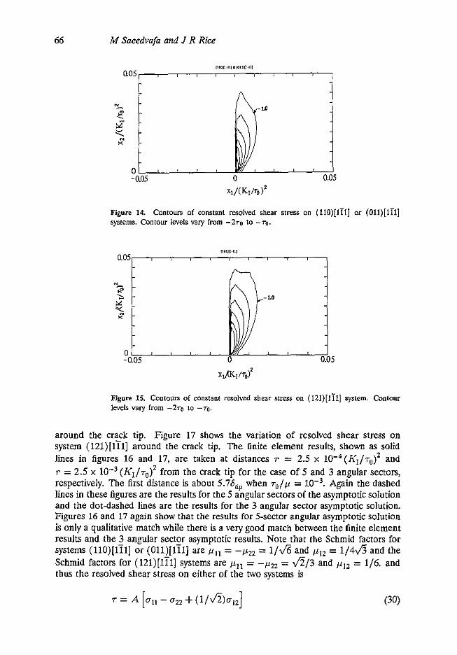
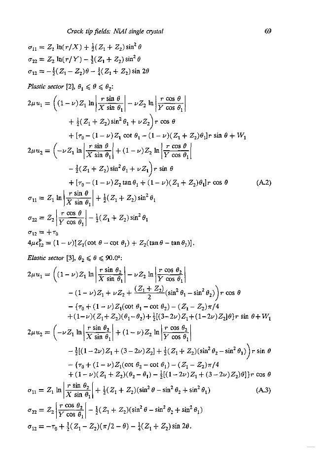
Figure 14 shows contours of resolved shear stress on (llO)[lil] slip system, assumed not to be activated in the present solution. Figure 15 shows wntom of resolved shear stress on (121)[1?1] slip system. Among the members of the {110}(111) and {112}(111) systems capable of sustaining large plastic flow (p33 = 0 which means = 0 for non-zero in-plane e:,), these two were chosen since they exhibited the largest zone over which the resolved shear stress is larger than 7,. Since the Schmid factor for some of the systems are the same in this orientation under plane strain conditions, the resolved shear stress is equal for some of these systems, thus figure 14 also shows the resolved shear stress on (011)[1?1] system. Both of these two systems form an angle of 35.26O with the crack face. The wntour levels shown in figures 14 and 15 vary from -27, to -rU, with the outermost wntour representing
stress exceeds r, are of the order of plastic zone size R, = 0.044(1<,/~,)~. Figure 16 shows the variation of resolved shear stress on systems (llO)[lil] or (Ol l ) [ l i l ]
7 = -7 ,. As can be seen in these two figures the largest zones in which resolved shear
66 M Saeedvafa and J R Rice
XI/(KI/TO)'
~ i g u r e 14. Contours of constant re~o~ved shear stress on (iio)[iii] or (oii)[iii] systems. Conlour levels vary from -2ro to -TO.
111,111.111
0.051 1
X,P(r/To?
Figure 15. Contours of conslant resolved shear stress on (lZl)[lil] system. Contour levels valy from -270 to -70.
around the crack tip. Figure 17 shows the variation of resolved shear stress on system (121)[lil] around the crack tip. The finite element results, shown as solid lines in figures 16 and 17, are taken at distances T = 2.5 x lO-"((h;/r,)* and T = 2.5 x 10⁻³(I<1/~u)z from the crack tip for the case of 5 and 3 angular sectors, respectively. The first distance is about 5.7~5,;~ when r0/p = Again the dashed lines in these figures are the results for the 5 angular sectors of the asymptotic solution and the dot-dashed lines are the results for the 3 angular sector asymptotic solution. Figures 16 and 17 again show that the results for 5-sector angular asymptotic solution is only a qualitative match while there is a very good match between the finite element results and the 3 angnlar sector asymptotic results. Note that the Schmid factors for systems (llO)[lil] or (Oll)[l i l] are f i l l = -pZz = l/& and p 1 2 = 1 / 4 4 and the Schmid factors for (12l)[lil] systems are pl, = - f izz = &/3 and p I Z = 1/6. and thus the resolved shear stress on either of the two systems is
Crack lip fields: NiAl single ciystal 67
where A = l /& for (llO)[lil] or (Oll)[lil] systemsand A = f i / 3 for (121)[lil] system. Thus substituting the equations for oil, crZ2 and u , ~ in each of the sectors into equations (30) leads to
T = A [ f ( B ) In T + d e ) ] (31)
where f and g are also dependent on the constants of each sector. Thus as can be seen from equation (31), as well as figures 16 and 17, the resolved shear stress in these two systems (as well as many other members of their respective set of systems) is infinite at the crack tip due to the singular stress field. Realistically, one should probably cutoff the In T at a distance of T m 26,,. Thus flow on these two systems could contribute to alleviate the unrelaxed crack tip stresses, even though the critical resolved shear stress on these systems is much larger than that of the {llO}(loO) slip system at room temperature. Note that there are 7 independent slip systems in the {112}(111) family and 5 independent slip systems in the {110}(111) family with 4 and 3 systems in each respectively which are capable of sustaining large plastic flow. Thus activation of either of these two systems is sufficient for a bounded stress field. The tensile stress directly ahead of the crack is about ozz = 15.57,, from finite element results of figure 9, at the cut off distance T = 26,,, which for = W3, corresponds to I n [ r / ( 1 ~ , / ~ ~ ) ~ ] = -9.3. The competition at the crack tip is between cleavage, aided by such large stresses, and plastic relaxation.
\I -I5...... -20 0 45 80 135 LBO
-4 0 45 80 135 180
8
-5
-10
\ I
b : 0 45 80 135 180
3 2 3 Sector Asymp. -
- 1
-2
-3
-4 0 45 80 135 180
8
-5
-10
\ I
b : 0 45 80 135 180
3 2 3 Sector Asymp. -
0
8
Figure 16. Varialion-of resolved shear stress on Figure 17. Variation of resolved shear stress on (l lO)[li l] or (011)[111] systems around the crack (121)[li l] system around the crack tip, for 5 and lip, for 5 and 3 angular seclor zones. 3 angular sector zones.
68
5. Conclusions
The asymptotic as well as the finite element results show that the elastic-ideally plastic NiAI single crystal with the crack on the (010) plane growing in the [loll direction has a In T type singularity in the stresses, at least within the 'small strain' theory, when there is only one system, (lOl)[OlO], which is capable of sustaining large plastic Row. The field has a distinct shear displacement discontinuity at 0 = 90° along the dip plane trace of the (101)[010] system and is divided into two zones, an inner one containing 5 angular sectors alternating from elastic to plastic, and an outer one with 3 angular sectors. The zone in which the solution contains 5 angular sectors has two plastic sectors, one at 7.6O < 0 < 79.3O, vanishing at distances Rf, = 3.0 x 10⁻⁴(Ii,/7,)2 from the tip, in which uI2 = + T ~ , and one at 90° < 0 < 172.5O in which uI2 = -rW Over distances larger than Rb from the tip the field is divided into 3 angular sectors with the plastic sector at 90a < 6' < 116O in which uI2 = - T ~ , vanishing at R, = 0.044(1CI/70)2.
The contours of constant resolved shear stress on systems {110}(111) and {112}(111), which can become activated at higher temperature, shows that the largest zones over which the resolved shear stress on either of these two systems is larger than ru is of the same order as R,. The largest of these two zones are associated with the resolved shear strcss on (110)[111] and @ll) [ l i l ] systems (figure 14) and (12l)[lil] systems (figure 15) whose traces in the (101) plane form an angle of 35.26O with the crack face. Although the critical resolved shear stress on either of these two systems is larger than that of the {110}(100) system, the resolved shear stress on all members of these two set of systems is very large at the crack tip due to the stress singularity, thus one or the other of these two systems could become activated at sufficiently high temperature, relieving the stress singularity. Presumably, at lower temperatures, the maximum tensile stress uz ahead of the tip becomes sufficiently large as to cause cleavage before such additional systems can be activated.
M Saeedvafa and J R Rice
Acknowledgment
This study was supported by the Office of Naval Research, Mechanics Program, under grant number N00014-4)-5-1379 to Harvard. The computational aspect of this work was partly performed on a Cray YMP computer at the Pittsburgh Supercomputing Center under a grant from NSE The ABAQUS program was provided under an academic license by Hibbitt, Karlsson and Sorensen, Inc., Providence, Rhode Island.
70
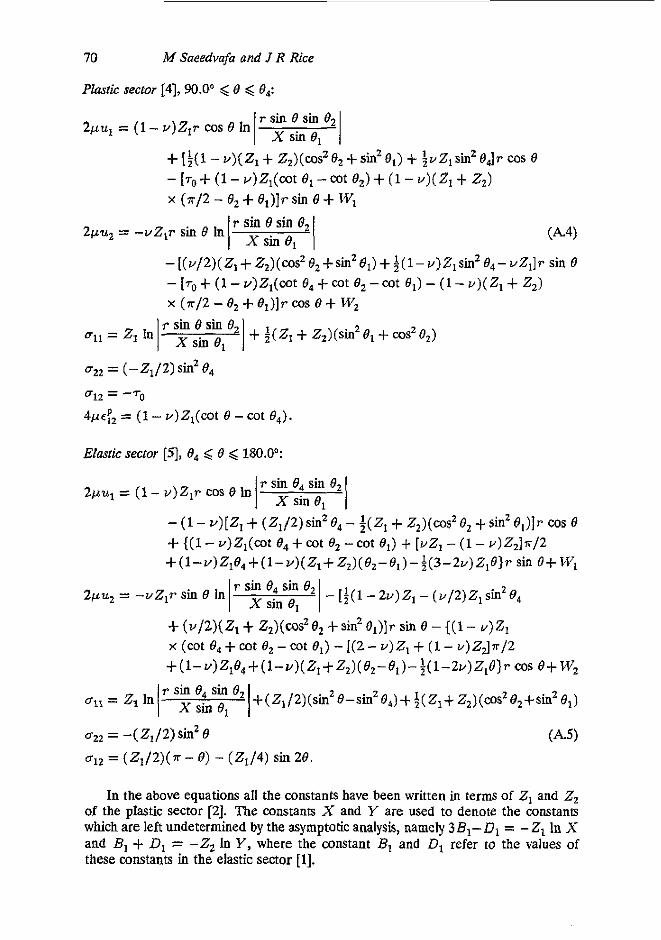
Phstk sector [4], 90.0' < e < 8,: M Saeedvafa and J R Rice
r sin 0 sin 82 I xs ine , I 2pu, = (1 - .)ZIT cos 0 In
u2, = ( -2 , /2) sinz e,
4 4 , = (1 - V)Z,(cot e -cot 8,).
ulz = -7,
EIastic sector [SI, 0, < 0 < 180.0°:
r sin 0, sin 6, 1 x s i n e , I 2p.q = (1 - v)Z,r cos 6 In
r sin 6, sin 8, 2pu2 = -uZ,r sin 0 In - I$( ' - 2U)Z1 - ( v / 2 ) Z 1 sinze,
U,, = -(Z1/2)Sin2O ~ l z = ( Z , / Z ) ( ~ - 6 ) - ( Z J 4 ) s i n 2 8 .
In the above equations all the constants have been written in terms of 2, and 2, of the plastic sector [Z]. The constants X and Y are used to denote the constan6 which are left undetermined by the asymptotic analysis, namely 38,-D1 = - 2, In X and B, + D, = -2, In Y, where the constant B, and D, refer to the values of these constants in the elastic sector [l].
Crack tip fields: NiAl single c y t a l
References
71
ABAQUS Manual version 4.8, 1989 (Providence, RI: Hibbitt, Karlsson and Sorensen, Inc.) Fleisher R L, Dimiduk D M and Lipitt H A 1989 Intermetallic compounds for strong high-temperature
materials: status and potential A m Rev. M a m Sci 19 231-63 Fu C L and Yo0 M H 1991 First-principles investigation of mechanical behavior of B2 lype aluminides:
FeAl and NiAl Marerial &search Society S p p . Roc. (Bastoq MA, 27-30 November 1990) vol 213 High-Temperawe Ordered Inremernuic Alloys W(Pitlsbur& PA Materials Research Society) pp 667-12
George E P and Liu C T 1990 Brittle fracture and grain boundary chemistry of mimalloyed NiA J: Marer Res. 5 754.52
Guha S, Munroe P R and Baker 1 1989 Improving the low temperature duaility of NiAI Matm'd Research Society Synp. Prof (Baron, MA, 29 November-1 December 1988) vol 133 High.Temperature Ordered Infennerallic Alloys I l l (Pitlsburg, PA Materials Research Society) pp 6 3 H
Huang Y 1991 A user-material subroutine incorporating single crystal plasticity in the ABAQLIS finite element program, MECH-178, (Haward University: Division of Applied Sciencss)
Kanchi M B, Zienkiewicz 0 C and Owen D R J 1978 The viscc-plastic approach U) problems of plasticity and creep involving geometric non-linear effects Int I . Numm'col Methods Ens 12 16941
Miracle D B, Russell S and Law C C 1989 Slip system modification in NiAl Mam'alResemh Society Sy" Proc. (Basron, MA, 29 November-1 December 1988) vol 133 High-Tmperaturc Ordered Inremerallic Alloys 111 (Pitlsburg, P A Materials Research Sociery) pp 225-30
Noebe R D. Cullers C Land Bowman R R 1992 The effect of strain rate and temperature on the tensile properfies of NiAl J: Marer Res. I 605-12
Peirce D, Asaro R J and Needleman A 1983 Material rate dependence and localized deformation in nystalline solids A m MeralL 31 1951-76
Rice J R 1987 Tensile crack tip fields in elastic-ideally plastic crystals Mech. Mato: 6 317-35 Russell S M, Law C C and Blackbum M J 1989 The effect of cobalt on martensitic toughening parameters
in NiAl Material Research Society w p . Proc. (Baron, MA, 29 November-I December 1988) voI 133 High-Tempenwe Ordered In"erollic Alloys Ill (Pitlsburg, PA: Materials Research Society) pp 627-32
Vedula K, Hahn K H and Boulogne B 1989 Room temperature tensile ductility in polycrystalline BZ NiAl Maroiol Research Society Sy". Roc, (Bmon, MA, 29 November-I December 1988) vol 133 High- Tnperoaue Ordered Inrometallic Alloys III (Pitlsburg, PA: Materials Research Society) pp 299-304
Vedula K and Stephens J R 1987 8 2 aluminides for high temperature applications Mmrid Research Society S p p . Roc. (Baston, MA, 2-4 December 1986) vol 81 High-Temperotum Ordered Inrmnerallic A I l q II (Pitlsburg, PA Materials Research Society) pp 381-91