27
1 CRD600SS Automatic Fitting Inserter OPERATIONS MANUAL ORIGINAL INSTRUCTIONS VERSION 3.1 LAST EDITED 10.17.2019 cleanroomdevices.com

1
CRD600SS Automatic Fitting Inserter
OPERATIONS MANUAL
ORIGINAL INSTRUCTIONS
VERSION 3.1
LAST EDITED 10.17.2019
cleanroomdevices.com

2
Table of Contents
Title Page………………………………………………………..…………………1
Table of Contents…………………………………………………………….……2
1.0 General Product & Safety Information……………………………………...3
1.1 Product Information
1.2 Safety Information
1.3 Lifting and Moving Safety
2.0 Installation/Setup……………………………………………………………5
2.1 Electrical
2.2 Air Supply
2.3 Pin Set Installation
2.4 Jaw Set Installation
2.5 Adjusting the stop gate
2.6 Magazine Installation
3.0 Operation…………………………………………………………………..13
3.1 Loading magazine and jaws
3.2 Fitting sensor lamp
4.0 Maintenance…………………………………………………………….....13
4.1 Daily
4.2 Every three months
5.0 Recommended Spare Parts………………………………………………...14
6.0 Product Specifications……………………………………………………..14
7.0 Trouble Shooting…………….…………………………………………….14
8.0 Durometer Scale…………………………………………………………...15
9.0 Electrical and Pneumatic Diagrams……………………………………….16
10.0 Alcohol Dispenser Option………………………………………….……...18
11.0 Parts List………………...………………………………………….……...23
12.0 Warranty…………………………………………………………………...26
12.1 Warranty
12.2 Warranty Period

3
1.0 General Product & Safety Information
Figure 1

4
1.1 Product Information
The Automatic Fitting Inserter is designed to hold and locate soft tubing while inserting a
fitting into the tubing.
The minimum/maximum outside tube diameter is 3/32” to 9/16”
1.2 Safety Information
This product uses air cylinders and electronic sensors to pneumatically actuate the closing
jaws. The unit is not intended for anything other than flexible tubing.
The desired air supply should be free of moisture/contaminates, and a minimum 100 psi
facility air supply is recommended. It is also recommended that a suitable filter/regulator
be installed onto the supply line prior to the unit to preserve the life expectancy of the air
components.
CRD600 AUTOMATIC FITTING INSERTER SAFETY NOTICE
PLEASE READ CAREFULLY BEFORE CONTINUING
Warning
The fitting inserter should only be operated by trained, qualified
personnel who have read and understand this manual.
The owner of this CRD600 is responsible for training all personnel to properly
operate this unit. Failure to follow instructions may result in serious personal
injury.
Never, under any circumstances operate the “Automatic Fitting Inserter” with
the cover or guarding removed or any safety device disabled.
1.3 Lifting & Moving Safety
Due to the weight of the unit (approximately 37 lbs/15 kg), the unit should always be
moved or repositioned by two (2) people to reduce the possibility of injury. (Figure 2)

5
Figure 2: Always Team Lift for Safety
2.0 Installation/Setup
Ensure all five (5) rubber feet are completely stabilized on your work surface prior to applying
air pressure to the unit.
2.1 Electrical Supply
Plug the electrical connector into the back of the fitting inserter and plug the 24VDC
power supply into a 110V outlet (220V for European power supplies). The smart
relay inside the machine may have as much as an eight (8) second power up
time before the fitting inserter becomes fully operational.
6
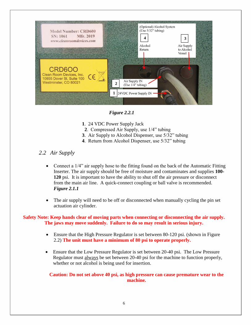
Figure 2.2.1
1. 24 VDC Power Supply Jack
2. Compressed Air Supply, use 1/4” tubing
3. Air Supply to Alcohol Dispenser, use 5/32” tubing
4. Return from Alcohol Dispenser, use 5/32” tubing
2.2 Air Supply
Connect a 1/4” air supply hose to the fitting found on the back of the Automatic Fitting
Inserter. The air supply should be free of moisture and contaminates and supplies 100-
120 psi. It is important to have the ability to shut off the air pressure or disconnect
from the main air line. A quick-connect coupling or ball valve is recommended.
Figure 2.1.1
The air supply will need to be off or disconnected when manually cycling the pin set
actuation air cylinder.
Safety Note: Keep hands clear of moving parts when connecting or disconnecting the air supply.
The jaws may move suddenly. Failure to do so may result in serious injury.
Ensure that the High Pressure Regulator is set between 80-120 psi. (shown in Figure
2.2) The unit must have a minimum of 80 psi to operate properly.
Ensure that the Low Pressure Regulator is set between 20-40 psi. The Low Pressure
Regulator must always be set between 20-40 psi for the machine to function properly,
whether or not alcohol is being used for insertion.
Caution: Do not set above 40 psi, as high pressure can cause premature wear to the
machine.
1
2
3 4

7
Figure 2.1.2 - Front Panel Layout
1. Power On/Off Switch
2. Alcohol Dispenser On/Off Switch
3. Alcohol Primer On/Off Switch
4. Low Pressure, Regulator/Gauge
5. High Pressure, Regulator/Gauge
6. Magazine
7. Operational Counter with reset
8. Fitting Sensor
1 2
3
4 5
6
7
8
8
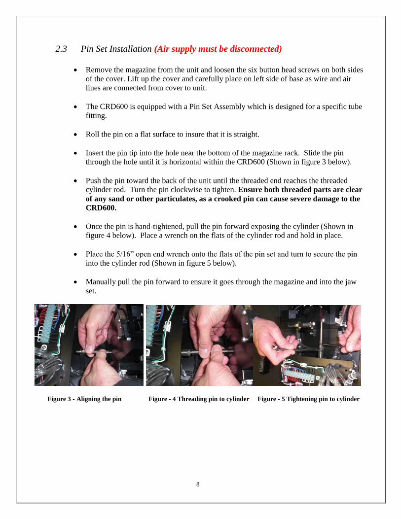
2.3 Pin Set Installation (Air supply must be disconnected)
Remove the magazine from the unit and loosen the six button head screws on both sides
of the cover. Lift up the cover and carefully place on left side of base as wire and air
lines are connected from cover to unit.
The CRD600 is equipped with a Pin Set Assembly which is designed for a specific tube
fitting.
Roll the pin on a flat surface to insure that it is straight.
Insert the pin tip into the hole near the bottom of the magazine rack. Slide the pin
through the hole until it is horizontal within the CRD600 (Shown in figure 3 below).
Push the pin toward the back of the unit until the threaded end reaches the threaded
cylinder rod. Turn the pin clockwise to tighten. Ensure both threaded parts are clear
of any sand or other particulates, as a crooked pin can cause severe damage to the
CRD600.
Once the pin is hand-tightened, pull the pin forward exposing the cylinder (Shown in
figure 4 below). Place a wrench on the flats of the cylinder rod and hold in place.
Place the 5/16” open end wrench onto the flats of the pin set and turn to secure the pin
into the cylinder rod (Shown in figure 5 below).
Manually pull the pin forward to ensure it goes through the magazine and into the jaw
set.
Figure 3 - Aligning the pin Figure - 4 Threading pin to cylinder Figure - 5 Tightening pin to cylinder
9
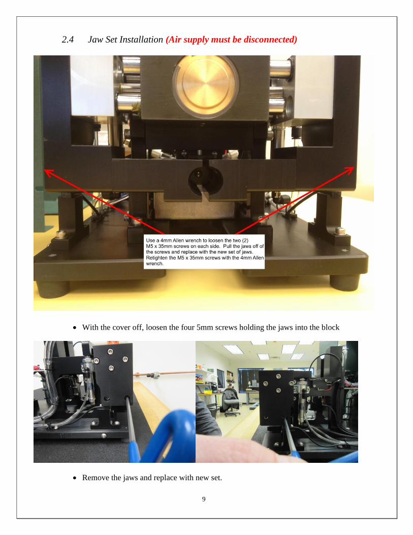
2.4 Jaw Set Installation (Air supply must be disconnected)
With the cover off, loosen the four 5mm screws holding the jaws into the block
Remove the jaws and replace with new set.
10
Retighten the four 5mm screws.
Check the pin-jaw alignment for pin concentricity. With the air turned off and the
magazine in, place a piece of tubing in the jaw set and clamp the tubing manually with
the jaws. Pull the pin forward manually through the magazine and ensure that it lines up
with the center of the inner diameter of the tubing. Gently rotate the pin to ensure that
there is no wobble in the pin head.
Failure to do so may result in severe damage to both the magazine and jaw set!
If any wobble is detected, recheck that the threads on the cylinder and pin set are clean.
If there is still a wobble, the Pin Set Assembly is bad and another must be used.
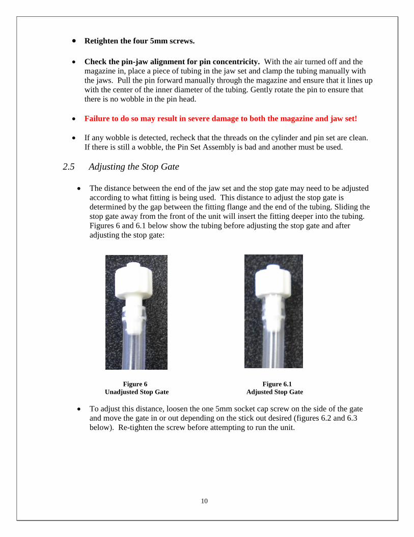
2.5 Adjusting the Stop Gate
The distance between the end of the jaw set and the stop gate may need to be adjusted
according to what fitting is being used. This distance to adjust the stop gate is
determined by the gap between the fitting flange and the end of the tubing. Sliding the
stop gate away from the front of the unit will insert the fitting deeper into the tubing.
Figures 6 and 6.1 below show the tubing before adjusting the stop gate and after
adjusting the stop gate:
Figure 6 Figure 6.1
Unadjusted Stop Gate Adjusted Stop Gate
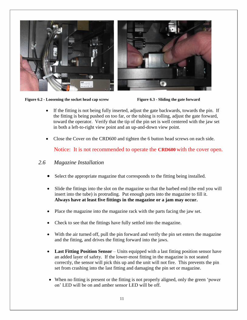
To adjust this distance, loosen the one 5mm socket cap screw on the side of the gate
and move the gate in or out depending on the stick out desired (figures 6.2 and 6.3
below). Re-tighten the screw before attempting to run the unit.
11
Figure 6.2 - Loosening the socket head cap screw Figure 6.3 - Sliding the gate forward
If the fitting is not being fully inserted, adjust the gate backwards, towards the pin. If
the fitting is being pushed on too far, or the tubing is rolling, adjust the gate forward,
toward the operator. Verify that the tip of the pin set is well centered with the jaw set
in both a left-to-right view point and an up-and-down view point.
Close the Cover on the CRD600 and tighten the 6 button head screws on each side.
Notice: It is not recommended to operate the CRD600 with the cover open.
2.6 Magazine Installation
Select the appropriate magazine that corresponds to the fitting being installed.
Slide the fittings into the slot on the magazine so that the barbed end (the end you will
insert into the tube) is protruding. Put enough parts into the magazine to fill it.
Always have at least five fittings in the magazine or a jam may occur.
Place the magazine into the magazine rack with the parts facing the jaw set.
Check to see that the fittings have fully settled into the magazine.
With the air turned off, pull the pin forward and verify the pin set enters the magazine
and the fitting, and drives the fitting forward into the jaws.
Last Fitting Position Sensor – Units equipped with a last fitting position sensor have
an added layer of safety. If the lower-most fitting in the magazine is not seated
correctly, the sensor will pick this up and the unit will not fire. This prevents the pin
set from crashing into the last fitting and damaging the pin set or magazine.
When no fitting is present or the fitting is not properly aligned, only the green ‘power
on’ LED will be on and amber sensor LED will be off.

12
If a fitting is properly seated in the magazine, the sensor will detect this and display a
Amber LED as well as the single green ‘power on’ LED. Shown in the figures below is
the sensor with and without fittings.
THIS SENSOR’S POSITION IS A FACTORY SETTING, ANY ADJUSTMENT
COULD CAUSE DAMAGE TO YOUR PIN SET, MAGAZINE OR JAW SET.
Figure 7 - Sensor without fittings Figure 8 - Sensor with Fittings
Adjusting Last Fitting Sensor Position – By adjusting the sensor up or down, you can position the
sensor properly. Using five (5) thin strips of paper, make a spacing gauge for the Last Fitting Sensor.
(Figure 9)
Figure 9 – Unit with 5 strips of paper Figure 9.1 – Verifying LFS light “ON”
When four (4) strips of paper are inserted between the magazine and the top of the magazine rack,
the Last Fitting Sensor light should be on. (Figure 9.1)
Fitting detected
Sensor Power
Last Fitting
Sensor Light
On
Four (4) strips
of paper
13
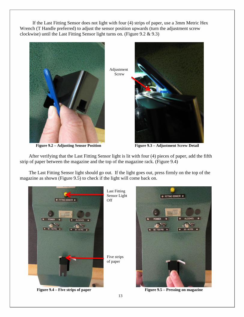
If the Last Fitting Sensor does not light with four (4) strips of paper, use a 3mm Metric Hex
Wrench (T Handle preferred) to adjust the sensor position upwards (turn the adjustment screw
clockwise) until the Last Fitting Sensor light turns on. (Figure 9.2 & 9.3)
Figure 9.2 – Adjusting Sensor Position Figure 9.3 – Adjustment Screw Detail
After verifying that the Last Fitting Sensor light is lit with four (4) pieces of paper, add the fifth
strip of paper between the magazine and the top of the magazine rack. (Figure 9.4)
The Last Fitting Sensor light should go out. If the light goes out, press firmly on the top of the
magazine as shown (Figure 9.5) to check if the light will come back on.
Figure 9.4 – Five strips of paper Figure 9.5 – Pressing on magazine
Adjustment
Screw
Last Fitting
Sensor Light
Off
Five strips
of paper

14
If the Last Fitting Sensor light remains lit with five (5) strips of paper between the magazine and the top
of the magazine rack, adjust the sensor downward (turning the adjustment screw counter-clockwise)
until the light goes out, then return to the previous steps detailing figures 9.1 – 9.3.
Once the Last Fitting Sensor is adjusted properly, it will remain lit with four (4) pieces of paper (Figure
9.1) and turn off with five (5) pieces of paper (Figure 9.4).
3.0 Operation
3.1 Loading Magazine and Jaws
Hook up the air FIRST and then turn on the power
Fill the magazine with fittings (5 minimum)
Insert a tube into the jaws, pushing forward until gate switch is hit.
Unit will cycle pushing the fitting into tube and then dropping the assembly down
3.2 Fitting Sensor Lamp
Yellow lamp is always on when machine is operating. If lamp is out it indicates that
the magazine is empty of fittings or the fitting is not all the way down in the proper
position in the magazine.
4.0 Maintenance
4.1 Daily
Once each day: the pin set should be retightened onto the air
cylinder. Loose pin sets can result in damage to the unit.
Once each day: ensure that the screws holding the jaws on are tight.
Loose screws will allow the jaws to move enough that fittings may
not properly insert into the tubing.
Once each day: disconnect the air at the rear of the unit and pull the
pin set toward the magazine hole and be sure that it enters the hole
freely (without hanging up on the side-wall). The pin set must enter
the magazine hole without moving the magazine or damage can
occur.
4.2 Every three months

15
Once every three months, the lid should be opened and the inside
around the jaw set and magazine should be cleaned via air (no more
than 30psi). This will remove any dust that has collected. At this time,
air connectors on the manifold should be checked for tightness. The
pin-set should be checked to make sure it is tight. Any dust or debris
which the blown air did not clean up should be wiped away.
Wipe down outer surfaces with alcohol, septihol or mild detergents as required.
5.0 Recommended Spare Parts
It is strongly recommended that you keep at least the following components
on-hand to minimize downtime should a component wear out or break.
1 additional Pin Set Assembly
1 additional Magazine
1 additional Jaw Set
6.0 Product Specifications
Unit Weight 37 LBS / 17 KG
Overall Dimensions 19.25 in. (48.9cm) lg. x 9.15 in.
(23.2cm) w. x 10.3 in. (26.2cm) ht.
Minimum/Maximum PSI 80 PSI /100 PSI
AC Power Supply 110-120 VAC, 50-60 Hz, 3A
7.0 Trouble Shooting
Operating Error Action
Unit does not operate.
1. Check the facility air connection.
2. Check both regulators are set to the proper
Pressure (Section 2.2 Air Supply)
3. Check electrical power, 110VAC & 24 VDC
4. Check all safeties:
Cover switch-make sure cover is
completely on
Magazine switch-make sure magazine
is pushed down all the way in the
magazine rack
Last fitting sensor- verify last fitting is
in position (Section 2.6 Magazine
Installation)
16
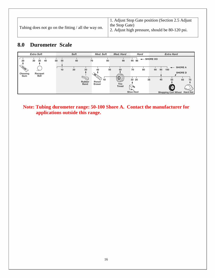
Tubing does not go on the fitting / all the way on.
1. Adjust Stop Gate position (Section 2.5 Adjust
the Stop Gate)
2. Adjust high pressure, should be 80-120 psi.
8.0 Durometer Scale
Note: Tubing durometer range: 50-100 Shore A. Contact the manufacturer for
applications outside this range.
17
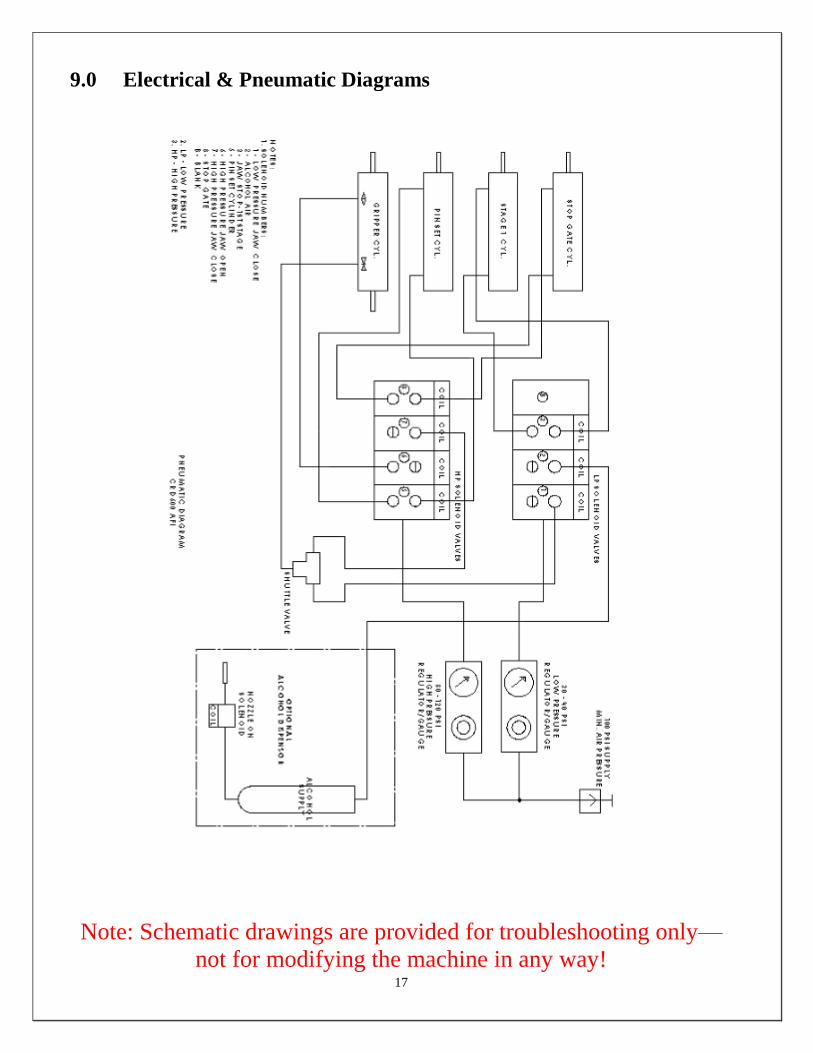
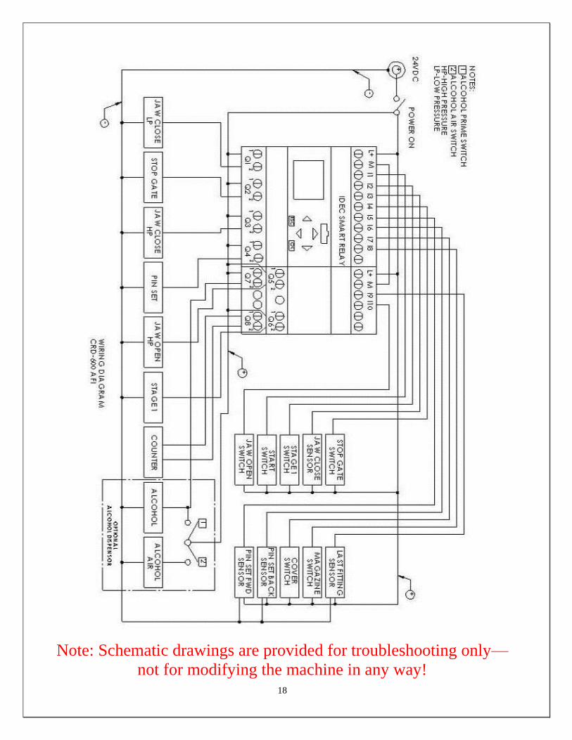
9.0 Electrical & Pneumatic Diagrams
Note: Schematic drawings are provided for troubleshooting only—
not for modifying the machine in any way!
18
Note: Schematic drawings are provided for troubleshooting only—
not for modifying the machine in any way!
19
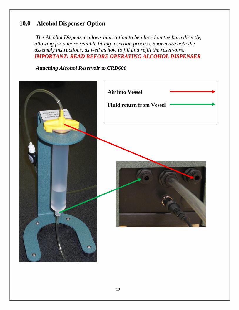
10.0 Alcohol Dispenser Option
The Alcohol Dispenser allows lubrication to be placed on the barb directly,
allowing for a more reliable fitting insertion process. Shown are both the
assembly instructions, as well as how to fill and refill the reservoirs.
IMPORTANT: READ BEFORE OPERATING ALCOHOL DISPENSER
Attaching Alcohol Reservoir to CRD600
Air into Vessel
Fluid return from Vessel
20
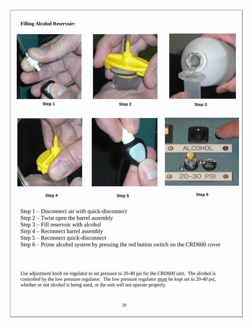
Filling Alcohol Reservoir:
Step 1 – Disconnect air with quick-disconnect
Step 2 – Twist open the barrel assembly
Step 3 – Fill reservoir with alcohol
Step 4 – Reconnect barrel assembly
Step 5 – Reconnect quick-disconnect
Step 6 – Prime alcohol system by pressing the red button switch on the CRD600 cover
Use adjustment knob on regulator to set pressure to 20-40 psi for the CRD600 unit. The alcohol is
controlled by the low pressure regulator. The low pressure regulator must be kept set to 20-40 psi,
whether or not alcohol is being used, or the unit will not operate properly.
Step 4
Step 1 Step 2 Step 3
Step 5 Step 6

21
Fitting Barb Alcohol Spray
Dispenser Nozzle
Fitting Barb
Dispenser Nozzle FRONT VIEW SIDE VIEW
Caution: Setting the regulator pressure above 40 psi will result in the pressure relief
valve opening.
DO NOT BYPASS RELIEF VALVE
Alcohol Dispenser Relief Valve
Aiming the Alcohol Dispenser Nozzle:
Accurate aiming of the dispenser nozzle is critical to ensuring proper performance. Adjust the alcohol
dispenser nozzle 1/16 – 1/8 of an inch in from the front of the barb, and at an oblique angle as shown in
the diagram below. This alignment will ensure that alcohol will flow around both sides of the barb.
22
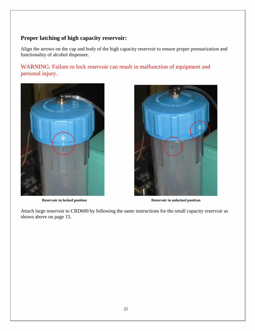
Proper latching of high capacity reservoir:
Align the arrows on the cap and body of the high capacity reservoir to ensure proper pressurization and
functionality of alcohol dispenser.
WARNING: Failure to lock reservoir can result in malfunction of equipment and
personal injury.
Reservoir in locked position Reservoir in unlocked position
Attach large reservoir to CRD600 by following the same instructions for the small capacity reservoir as
shown above on page 15.
23
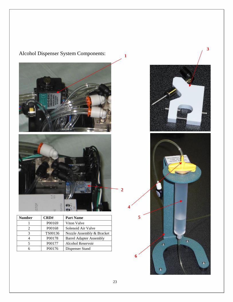
Alcohol Dispenser System Components:
Number CRD# Part Name
1 P00169 Viton Valve
2 P00168 Solenoid Air Valve
3 TS00136 Nozzle Assembly & Bracket
4 P00178 Barrel Adapter Assembly
5 P00177 Alcohol Reservoir
6 P00176 Dispenser Stand
2
1
3
4
5
6
24
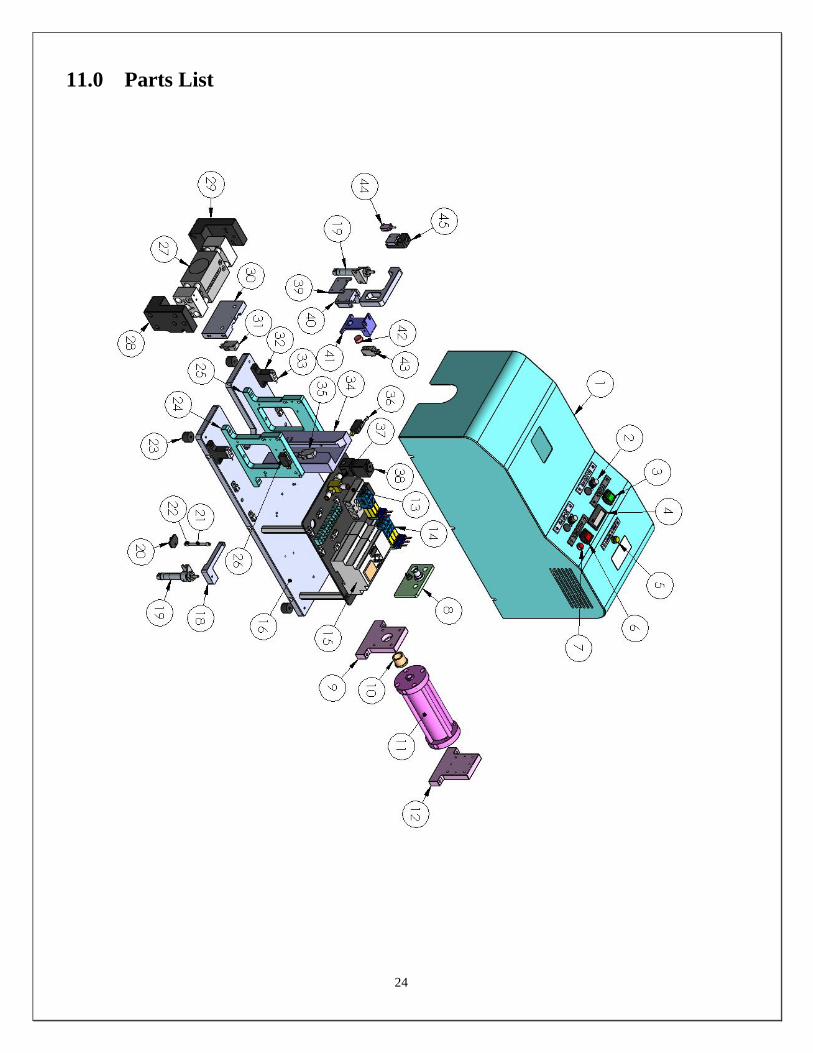
11.0 Parts List
25
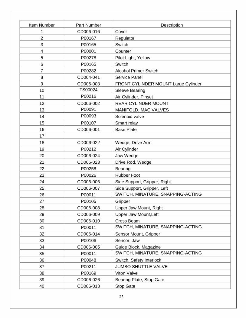
Item Number Part Number Description
1 CD006-016 Cover
2 P00167 Regulator
3 P00165 Switch
4 P00001 Counter
5 P00278 Pilot Light, Yellow
6 P00165 Switch
7 P00282 Alcohol Primer Switch
8 CD004-041 Service Panel
9 CD006-003 FRONT CYLINDER MOUNT Large Cylinder
10 TS00024 Sleeve Bearing
11 P00216 Air Cylinder, Pinset
12 CD006-002 REAR CYLINDER MOUNT
13 P00091 MANIFOLD, MAC VALVES
14 P00093 Solenoid valve
15 P00107 Smart relay
16 CD006-001 Base Plate
17
18 CD006-022 Wedge, Drive Arm
19 P00212 Air Cylinder
20 CD006-024 Jaw Wedge
21 CD006-023 Drive Rod, Wedge
22 P00258 Bearing
23 P00026 Rubber Foot
24 CD006-006 Side Support, Gripper, Right
25 CD006-007 Side Support, Gripper, Left
26 P00011 SWITCH, MINATURE, SNAPPING-ACTING
27 P00105 Gripper
28 CD006-008 Upper Jaw Mount, Right
29 CD006-009 Upper Jaw Mount,Left
30 CD006-010 Cross Beam
31 P00011 SWITCH, MINATURE, SNAPPING-ACTING
32 CD006-014 Sensor Mount, Gripper
33 P00106 Sensor, Jaw
34 CD006-005 Guide Block, Magazine
35 P00011 SWITCH, MINATURE, SNAPPING-ACTING
36 P00048 Switch, Safety,Interlock
37 P00211 JUMBO SHUTTLE VALVE
38 P00169 Viton Valve
39 CD006-026 Bearing Plate, Stop Gate
40 CD006-013 Stop Gate

26
41 CD006-012 BRACKET, STOP GATE BUTTON
42 CD006-015 Sensor, Button
43 P00011 SWITCH, MINATURE, SNAPPING-ACTING
44 TS00137 Last fitting Sensor
45 CD006-029 BASE, SENSOR BRACKET
45 CD006-030 SLIDER, SENSOR BRACKET
46 CD006-011 ACTUATOR DRIVE ARM

27
12.0 Warranty
12.1 Warranty The manufacturer warrants the product manufactured by it, when properly installed, operated, applied and
maintained in accordance with the procedures and recommendations outlined in the manufacturer’s operation
manual, to be free from defects in material or workmanship for a period as specified below, provided such defect
is discovered and brought to the manufacturer’s attention within the stated warranty period.
The manufacturer will repair or replace any product or part determined to be defective by the manufacturer within
the warranty period, provided such defect occurred in the normal service and not as a result of misuse, abuse,
neglect or accident. Normal maintenance items requiring routine replacement are not warranted. The warranty
covers parts and labor for the warranty period unless otherwise specified. Repair or replacement shall be made at
the factory or the installation site, at the sole discretion of the manufacturer. Any service performed on the product
by anyone other than the manufacturer must first be authorized by the manufacturer.
Unauthorized service voids the warranty and any resulting charge or subsequent claim will not be paid. Products
repaired or replaced under warranty shall be warranted for the unexpired portion of the warranty applying to the
original product.
The foregoing is the exclusive remedy of any buyer of the manufacturer’s product. The maximum damages
liability for the manufacturer is the original purchase price of the product or part.
THE FOREGOING WARRANTY IS EXCLUSIVE AND IN LIEU OF ALL OTHER WARRANTIES,
WHETHER WRITTEN, ORAL, OR STATUTORY, AND IS EXPRESSLY IN LIEU OF THE IMPLIED
WARRANTY OF MERCHANTABILITY AND THE IMPLIED WARRANTY OF FITNESS FOR A
PARTICULAR PURPOSE. THE MANUFACTURER SHALL NOT BE LIABLE FOR LOSS OR DAMAGE BY
REASON OF STRICT LIABILITY IN TORT OR ITS NEGLIGENCE IN WHATEVER MANNER
INCLUDING DESIGN, MANUFACTURE OR INSPECTION OR THE EQUIPMENT OR ITS FAILURE TO
DISCOVER, REPORT, REPAIR, OR MODIFY LATENT DEFECTS INHERENT THEREIN.
THE MANUFACTURER, HIS REPRESENTATIVE OR DISTRIBUTOR SHALL NOT BE LIABLE FOR
LOSS OF USE OF THE PRODUCT OR OTHER INCIDENTAL OR CONSEQUENTIAL COSTS, EXPENSES,
OR DAMAGES INCURRED BY THE BUYER, WHETHER ARISING FROM BREACH OF WARRANTY,
NEGLIGENCE OR STRICT LIABILITY IN TORT.
The manufacturer does not warrant any product, part, material, component, or accessory manufactured by others
and sold or supplied in connection with the sale of manufacturer’s products.
12.2 Warranty Period Parts and labor are for ninety (90) days from the date of shipment from the factory. Freight to the factory on units
that the manufacturer requests to be returned shall be paid by the purchaser, all return freight to be paid by the
manufacturer; means of transportation to be specified by the manufacturer.
For additional information contact: www.cleanroomdevices.com
Clean Room Devices, Inc.
10855 Dover Street, Suite 100
Westminster, CO 80021
303-438-0853


