56
Critical Process Vessels Superior Performance For Your Demanding Applications
Critical ProcessVessels
SuperiorPerformanceFor YourDemandingApplications

Saint-Gobain High-Performance Vessels
Our products are manufactured under a quality management system registeredas complying with ISO 9001:2000,which has been independently certifiedby BVQi.
Reliability and Toughness ExpandedSaint-Gobain Performance Plastics alsooffers high-quality blowers, safety equipment, fittings and accessories.Like our tanks, they feature the quality,reliability and toughness you’ve come to expect from Saint-Gobain.
Where Quality and ToughnessCount,There’s a Saint-GobainHigh-Performance TankSaint-Gobain Performance Plastics tanksare tough. They’re lightweight and corrosion-resistant. Their seamless designeliminates the major cause of leakageassociated with lesser quality plastictanks. Saint-Gobain Performance Plasticstanks won’t wick or crack like fiberglass.And, our tanks are easier to maintain andmuch less expensive than stainless steel.Saint-Gobain Performance Plastics tanksare rotationally molded in a variety of high-quality virgin resin materials tomatch your specific application.
Service and Support—We’re Here When You Need UsSaint-Gobain Performance Plastics offersfree technical assistance and a knowl-edgeable network of sales representa-tives committed to your complete satis-faction. We’ll help you select the rightSaint-Gobain Performance Plastics product for your specific requirements.We’ll educate, inform and demonstratethe advantages our tanks offer over othercompetitive containers. And with ourexclusive warranty, we’ll supply you witha reliable system that will last and last.
Saint-Gobain Performance Plastics Rotational-Molded Tanks Offer Distinct Advantages
Plastic tanks which are subject to chemi-cal, physical and/or thermal exposureshould be inspected on a routine basis for any signs of leaking, cracking, discol-oration, bulging or other deviations fromthe “as new” condition. The frequency ofinspection will be highly dependent uponactual use conditions, as well as the ageof the tank. Specific guidelines must bedetermined by the user dependent uponactual use conditions. Saint-GobainPerformance Plastics cannot provide
Service Depends on Contents, Location, Temperatureand Other Conditions• Lower cost than stainless steel or
fiberglass
• Virtually maintenance-free
• Seamless construction for easy cleaning
• Available in a wide variety of resinsand leakproof service
• Most tanks have a visible liquid level
• Controlled wall thickness withoutcorner thinning
• Lightweight; less than one-half theweight of steel
Special Notes• Tanks with Fiberglass-Reinforced
Polyester (FRP) Casings offer service tohigher temperatures and with higherspecific gravity contents.
• Operating conditions and chemicalusage can decrease maximum servicetemperatures.
• Continuous service temperatures inranges above ambient can affecttanks in at least two ways: 1) the use-ful life of the tank may be shortened;and 2) the ability of the container tomaintain its shape may decrease,perhaps resulting in distortion.
specific guidelines due to the wide varietyof applications and their effects on plastic tanks. Please consult this catalogor contact Saint-Gobain PerformancePlastics for more information.
Quality Design Assures Long, Reliable LifeOur tanks feature generous, rounded corners that have less molded-in stress.This construction makes them less likelyto crack and easier to clean.
Other Tanks Saint-GobainHigh-Performance Vessels

By Product and SubjectBy Catalog Number Series
Introduction and InformationHow to Select Your High-Performance Tank 2
Technical Information . . . . . . . . . . . . . .37
Food Grade Resins, Plastic Products for Biotechnology, Dimensions and Wall Thickness, Physical Service Capabilities,Environmental Stress-Cracking, TensileStresses, Common Stress-Cracking Agents, Susceptibility to Stress-Cracking,Physical Service Capabilities,Ultraviolet (UV) Stabilization
Chemical Storage . . . . . . . . . . . . . . . . . .38
Storage of Sodium Hypochlorite,Using Tanks with Common Chemicals
Chemical Resistance Charts . . . . .39-44
Warranty and How to Order . . . . . . . . .45
Open-Top TanksGeneral Guide to Open-Top Tanks . . . . 3
Flat-Bottom Cylindrical Tanks . . . . . . . . 4
Conical-Bottom Tanks . . . . . . . . . . . . . . . 5
Rectangular Tanks. . . . . . . . . . . . . . . . . 6-7
Tank Flange Styles, Tanks With Flat Wide Flanges, Flat-Flange Rectangular Tanks
Cylindrical Tanks . . . . . . . . . . . . . . . . . . . . 8
Tapered General Purpose Containers,Closed-Dome Tanks
Cylindrical Tank Stands . . . . . . . . . . . . . . 9
Floor Stands, Elevated Stands for Flat-Bottom and Conical-Bottom Tanks, Options
Open-Top Tank Mixers . . . . . . . . . . . . . . 10
LIGHTNIN Mixer Features, Options
Open-Top Tank Fittings/Accessories . . . . . . . . . . . . . . 11-13
Floating Covers, Installed Hinges for Cylindrical Tank Covers, Installed and Loose Fittings, Bulkhead Fittings
Guidelines for Installation . . . . . . . . 14-15
Putting It All Together . . . . . . . . . . . . . . 16
2624 18
2650 18
2653 21
2654 21
2656 25
2658 25
2660 23
2661 23
2662 24
2663 24
2665 24
2666 24
2669 24
2670 23
2671 23
2672 23
2673 22
2674 22
2677 26
2678 26
2680 26
2681 26
2685 24
2690 19
2691 19
2692 23
2695 22
2696 22
2697 22
2710 20
2711 20
11100 4
11102 4
11150 8
11200 4
11250 8
11300 4
11500 4
12000 7
12300 7
14100 7
14150 6
14200 7
14250 6
14300 7
14350 6
14500 7
15000 6-7
16120 5
16220 5
16320 5
16520 5
18100 4
18200 4
18300 4
19000 4
19009 9
19010 9
20010 9
25100 33
25300 33
48080 13
48090 13
51105 30
51109 30
51305 30
51309 30
53009 32
53109 32
53309 32
54100 4
54102 4
54104 11
56104 8
59000 35
59040 33
63100 10
63600 10
71300 43
71309 42, 34
71320 40, 43
71330 40, 43
71400 43
71409 42
71420 40, 43
71430 40, 43
71500 43
71509 42
71520 40, 43
71530 40, 43
716421 13
716422 13
72509 42
72510 44
72511 44
72520 41-43
72521 40-43
72530 41-43
72531 40-43
72609 42
72620 41-43
72631 40-43
72721 40-43
72730 42-43
72731 40-43
72821 40
72830 42-43
72831 40-43
76000 13, 35
86200 34
86301 34
86302 34
86303 35
86304 34
86320 34
86400 34
86501 34
86626 34
86650 34
86651 34
86780 35
86781 35
86890 35
86891 35
86900 34
87001 13
87005 12
87006 12
87500 11
88001 13
89005 12
93400 12
93420 13
93840 12
93841 12
93857 12
93858 12
93859 12
95840 12
95857 12
96000 13
96423 12
97001 13
97003 13
97006 13
97103 13
97424 13
98001 13
98003 13
98103 13
Cat. No. Page Cat. No. Page Cat. No. Page Sanitary VesselsSanitary Tanks . . . . . . . . . . . . . . . . . . . . . 17
Closed-Dome Bio Tanks . . . . . . . . . . . . . 18
Closed-Dome Bio Tank Accessories
Sanitary Conical Process Vessels . . . . . 19
Processing Tank Systems,Conical-Bottom Processing Tanks:Polypropylene and Polypropylene Fluoride
Sanitary Conical Tank Stands . . . . . . . 20
Conical-Bottom Portable Tank Stands,Industrial-Style Stand Option
Sanitary Tank Mixers . . . . . . . . . . . . . . . 21
BioTech Mixing Systems,BioTech Mixer Overhead Drives,Lower Assemblies/Shafts and Impellers
Sanitary Drain Options . . . . . . . . . . . . . 22
Conical Drain Valve,Diaphragm Valve, Ball Valve
Sanitary Fittings and Accessories. . . . . . . . . . . . . . . . . . . . . 23-26
Installed Sanitary Ferrules,Sanitary Gaskets, True Union Clamps,End Caps, Sight Caps, Elbow Sweeps,Concentric Reducers, Heavy-Duty Clamps, Siphon Tubes, Rotary Spray Jet,Mounting Apparatus for Spray JetNozzle, Sani-Sampling Devices,1-inch Ladish Charging Elbow
Proper Placement and Autoclave Instructions. . . . . . . . . . . . . . 27
Putting It All Together . . . . . . . . . . . . . . 28
Bulk Storage TanksBulk Storage Tanks . . . . . . . . . . . . . . 29-35
BlowersBlowers Introduction. . . . . . . . . . . . . . . 36
Blower Performance Curves . . . . . . 37-38
Four Steps to Blower Selection . . . . . . 39
Blower Specifications . . . . . . . . . . . 40-44
Table of ContentsI N T R O D U C T I O N
1

Tank Resin Selection Guide — Typical Properties and Applications1
NOTES:1 At low temperatures, protect all tanks from impact. Below 40°F/4°C, specify XLPE Tanks.
2 Cross-linked, high-density polyethylene is recommended for use with stress-cracking agents.3 Brittleness temperature per ASTM test D-746. The impact resistance of most rotomolded tanks declines at freezing temperatures.
Cross-linked, high-density polyethylene tanks are well suited for cold storage.4 The resins used in Saint-Gobain Performance Plastics linear low- and high-density polyethylene and polypropylene tanks comply with 21 CFR
Regulation 177.1520. Polyethylene meets all food-grade requirements; however, this product is restricted to contacting food only of the types identified in 21 CFR 176.170 Table 1, under categories 1, IV-B, VII-B, VIII, and under conditions of use B through H described in Table 2 of 21 CFR 176.170. Saint-Gobain rotomolded polypropylene complies with FDA 21 CFR 177.1520 (c) 3.1 regulation. The resin used in PVDF tanks complies with 21 CFR 177.2510.
5 Open-top tanks do not contain UV stabilizer; black is recommended for certain applications. Bulk tanks are UV-stabilized and may be used outdoors.
How To Select Your High-Performance TankI N T R O D U C T I O N
2
Material General Chemical Stress-Crack2 Maximum Service Brittleness Impact Can Be Welded Food-Grade Color RESIN Resistance Resistance Temperature Temperature Resistance3 (Hot Gas) Acceptability
HDPEHigh DensityPolyethylene
XLPECross-LinkedHigh DensityPolyethylene
PPPolypropylene
PVDFPolyvinylideneFluoride
Very Good
Very Good
Very Good
Excellent
Good
Excellent
Excellent
Excellent
140°F60°C
140°F60°C
220°F104°C
230°F110°C
-94°F-70°C
-180°F-118°C
32°F0°C
-40°F-40°C
Good
Excellent
Fair
Fair
Yes
No
Yes
Yes
Yes4
Naturaland Black
No
Yes4
Yes4
White
Yellow
Off-White
Off-White
Tank Resin Selection Guide — (continued)
Material ADVANTAGES AND APPLICATIONS DO NOT USE WITH:RESIN
HDPEHigh DensityPolyethylene
•Hard, smooth finish•Good temperature
resistance•Less expensive than stain-
less steel or fiberglass
•Storing caustics•Metal finishing•Storing organic and
inorganic acids•Water treatment
•Dispensing lab and photo chemicals
•Plating•Brine
XLPECross-LinkedHigh DensityPolyethylene
•Suitable for many corro-sives not handled by FRP
•Storing corrosives, includ-ing sulfuric, hydrochloricand hydrofluoric acids
•Storing sodium hypochlo-rite (See statementon page 38)
•Storing organic and inorganic chemicals andcompounds
•Chemical processing•Storing boiler treatment
chemicals•Water and wastewater
treatment
PPPolypropylene
•Good resistance to manyorganic chemicals
•Less expensive than comparable stainlesssteel tanks
•Weldable PP fittings available
•Plating and pickling lines•Sanitary process tanks
•Etch tanks for processingsilicone wafers
PVDFPolyvinylideneFluoride
•Superior resistance to inorganic acids, strongoxidizing agents andhalogenated compounds
•High-purity; does notcontaminate process fluids
•PVDF Schedule 80 threadedfittings available
•Etch tanks for processingsilicone wafers
•Ultra-pure water storage(not potable)
•Precious metal recovery•Storing and processing
halogenated compounds(i.e., bromine)
•Storing bleach and sulfuric acid for pulp and paper processing
•Industrial battery casings•Insecticide manufacturing
Strong oxidizing agents,aromatic hydrocarbons,halogenated-aliphatic hydrocarbons,liquefied petroleum gas, solvents
Strong oxidizing agents,aromatic hydrocarbons,halogenated-aliphatic hydrocarbons,liquefied petroleum gas, solvents
Strong oxidizing agents;aromatic or chlorinated hydrocarbons,sub-freezing temperatures
Ketones, esters and hot,concentrated caustics; nascentchlorine gas and concentrated caustic soda
NATURAL, UNPIGMENTED NATURAL, UNPIGMENTED

Plastic Tanks For High-Purity Storage
Saint-Gobain Performance Plastics high-performance tanks are the best andtoughest in the industry. Exacting CAD-based designs, the highest quality virginresins and tough construction provideexcellent solutions for general purposeapplications. The tanks are translucentand feature molded-in graduations.
Each tank comes with a matching coverthe same thickness as the wall. Theopen-top unit covers fit like a shoe box;bolted or welded covers are availableupon request.
Closed-dome tanks are available for applications requiring a completelyclosed vessel. The 6" threadedpolypropylene covers prevent evapora-tion and spills.
Our open-top tanks are rated for usewith 1.8 specific gravity media. If a
Cylindrical tanks feature a stepped-flangedesign that adds rigidity and strengthwhile helping to contain drips. Tanks over 30 gallons feature a slightly raised bottomthat channels liquids to tank walls andfittings. Spoked bottoms reinforce largertanks over 55 gallons and provide near-total drainage.
fiberglass casing is used, the rating goes up to 2.2. Casings provide structuralsupport and prevent bulging at the bot-tom of the tank. They should be usedwith rectangular units with any dimen-sion greater than 18 inches. Casings arealso required for use with media havinga specific gravity greater than 1.8 or foruse at prolonged elevated temperatures.
Our stands, mixers, and casings havebeen pre-engineered for compatibility.Simply choose your tank size and thesize codes of the accessories will match.
Fabrication is available for all Saint-Gobain Performance Plasticstanks. Modifications can be made to thecovers or the sides. Contact customerservice for quotations. Welded andmechanical fittings can be installed,as well as a full line of accessories.
General Guide to Open-Top Tanks
3
O P E N - T O P T A N K S
Materials Overview
High Density Polyethylene (HDPE):
• FDA 21 CFR 177.1520
• Hard, Smooth Finish
• Very Good Chemical Resistance
• Good Stress-Crack Resistance
• Max Service Temp—140°F
• Translucent White
Cross-Linked Polyethylene (XLPE):
• Not FDA
• Cannot be welded
• Better Chemical Resistance to HDPE
• Excellent Stress-Crack Resistance
• Max Service Temp—140°F
• Yellow (Bulk Tanks—Gray)
Polypropylene (PP):
• FDA 21 CFR 177.1520
• USP Class VI, Non-cytotoxic
• Hard, Smooth Finish
• Very Good Chemical Resistance
• Excellent Stress-Crack Resistance
• Max Service Temp—220°F
• White
Polyvinylidene Fluoride (PVDF):
• FDA 21 CFR 177.2510
• High-Purity Material/Low Extractables
• Larger sizes require casings
• Inherent UV Resistance
• Excellent Chemical Resistance
• Max Service Temp—230°F
• Off-White
Maximum service temperature listings refer to temperatures that should not be exceeded for thematerials utilized in the specific product line. Many factors including media, specific gravity ofmedia, external stresses, product geometry, environment, and others affect suitability of material.
Structural Designs
STEPPED-FLANGE UP TO 30 GALLON RAISED BOTTOM
55 AND 80 GALLONSPOKED BOTTOM
100 GALLON AND ABOVESPOKED BOTTOM

*7.5- and 10-gallon cylindrical tanks do not have liter calibrations **Casing required For replacement spigot, see page 13†Within UPS size restrictions ††These sizes quoted on request N/A=Not AvailableMaximum service temperature listings refer to temperatures that should not be exceeded for the materials utilized in the specific product line.Many factors, such as chemical resistance, specific gravity, external stresses, product geometry, environment and many others affect the suitability of a particular product. For additional information, contact Saint-Gobain Performance Plastics.
• All tankscome withcovers
• Brim capacity10% over WARNING: Never use FRP casings alone as
a tank. Always use a liner. For continuousservice at elevated temperatures or storageof high specific-gravity materials, always use an FRP casing with your tank.
Flat-Bottom Cylindrical TanksO P E N - T O P T A N K S
4
Size Size Grad. Nom. Tank Natural w/ Spigot Natural Natural Natural Natural Natural Tank w/Casing(gallons) Code (gal./liter) Dimensions Cat. No. Cat. No. Cat. No. Cat. No. Cat. No. Cat. No. Cat. No.
(O.D. x Depth, in.) 11100 11102** 54100 54102 11300 11200 11500
Approx. Shipping(wt., lbs.)
HDPE, Heavyweight(Avail. in Black,
No. 18100)
XLPE,Heavy-weight(Avail. in
Black,No. 18300)
PP,Heavy-weight(Avail. in
Black,No. 18200)
PVDF
HDPE,Lightweight
5
7.5
10
15
30
55
80
100
150
200
275
360
500
1,000
-0005
-0007
-0010
-0015
-0030
-0055
-0080
-0100
-0150
-0200
-0275
-0360
-0500
-1000
0.5/2
0.5/*
1/*
1/4
2.5/10
2.5/10
5/20
5/20
10/40
25/200
25/100
25/100
25/100
50/250
11 x 15—
12 x 18—
13 x 20—
13 x 27—
18 x 3019-1/8 x 30-1/4
22 x 3623 x 36-1/4
24 x 4824-3/4 x 48-1/4
28 x 4429-3/16 x 44-1/4
31 x 4932-7/16 x 49-1/4
36 x 5137-1/2 x 51-1/4
42 x 4943-1/2 x 49-1/4
48 x 4948-3/8 x 49-1/4
53 x 6254-1/8 x 62-1/4
66 x 7267-1/2 x 72-1/4
3/16
3/16
3/16
3/16
3/16
1/4
1/4
1/4
1/4
1/4
1/4
1/4
5/16
7/16
3/16
3/16
3/16
3/16
3/16
1/4
N/A
N/A
N/A
N/A
N/A
N/A
N/A
N/A
3/32
3/32
3/32
3/32
3/32
3/32
N/A
N/A
N/A
N/A
N/A
N/A
N/A
N/A
3/32
3/32
3/32
3/32
3/32
3/32
N/A
N/A
N/A
N/A
N/A
N/A
N/A
N/A
3/16
3/16
3/16
3/16
3/16
1/4
1/4
1/4
1/4
1/4
1/4
1/4
5/16
7/16
3/16
3/16
3/16
3/16
3/16
1/4
1/4
1/4
1/4
1/4
1/4
1/4
N/A
N/A
3/32
N/A
3/32
3/32
3/32
1/8
1/8**
1/8**
1/8**
1/8**
1/8**
N/A
N/A
N/A
4-1/2†
6-1/2†
6-1/2†
8†
12†
20-1/2†
N/A
N/A
N/A
N/A
N/A
N/A
N/A
N/A
5†
7-1/2†
9†
11-1/2†
19†
31
50
50
60
67-1/2
101
120
150
389
N/A
N/A
N/A
N/A
42†
53
80
80
135
150
200
296
300
500
(CASING DIM.)
Nominal Wall Thickness By Resin
STEPPED-FLANGE 1000-GALLON COVER
Maximum Service Temperature 140°F60°C
140°F60°C
140°F60°C
220°F104°C
230°F110°C
Light Heavy 19000
Flat-Bottom Cylindrical Tanks
CAT. NO. 11100 CAT. NO. 11102 CAT. NO. 11300

Conical-Bottom Tanks
5
O P E N - T O P T A N K S
Conical-Bottom Tanks
*To cone flat N/A = Not Available**Casing required†Within UPS size restrictionsCone Angles: 30° on 10, 30, 55, 100, 150, 250 gallon
18° on 400 gallon & 45° on 500 gallon
• 30° cone angle (18° for 400 gallons,45° for 500 gallons)
• Complete drainage
• Better dispersal of solids
• Easy installation of welded or bulkhead fittings
• HDPE and polypropylene resins comply with 21 CFR Reg. 177.1520(Refer to chart on page 3) PVDF 21 CFR 177.2510
• Require metal stands (see page 9)
• Clearance from the floor to bottom of the tank is 18 inches (12 inches on10-gallon tank)
WARNING: Never use FRP casings alone asa tank. Always use a liner. Always use an FRPcasing with your tank for continuous serviceat elevated temperatures, or storage of highspecific-gravity materials.
Size Size Grad. Nom./Dim. Bottom Natural Cat. Natural Cat. Natural Cat. Natural Cat. (wt., lbs. (wt., lbs.Tank(gallons) Code (gal./liter) (O.D. x Depth*) Flat Dia. No. 16120 No. 16320 No. 16220 No. 16520 17000 Tank) w/ Casing)
Approx. Shipping
Maximum Service Temperature
HDPE
CAT. NO. 16120
140°F60°C
140°F60°C
220°F104°C
230°F110°C
XLPE PP PVDF Casing
10
30
55
100
150
250
400
500
-0010
-0030
-0055
-0100
-0150
-0250
-0400
-0500
1/5
2.5/10
2.5/10
5/20
5/20
25/100
25/100
25/100
13-1/4 x 23
18 x 35
22 x 44
32 x 38
32 x 57
43 x 54
56 x 52
53 x 80
3
3
3
5
5
5
7
7
5/32
3/16
3/16
1/4
1/4
5/16
3/8
5/16
5/32
3/16
3/16
1/4
1/4
5/16
3/8
5/16
5/32
3/16
3/16
1/4
1/4
5/16
3/8
N/A
3/32
3/32
1/8
1/8
1/8**
1/8**
N/A
N/A
N/A
3/32
3/16
3/16
3/16
3/16
1/4
1/4
10†
18
34
48
82
112
140
215
N/A
37
53
95
150
241
230
331
Conical-Bottom Cylindrical Tanks — Nominal Wall Thickness By Resin
TANKS WITH CASING

Rectangular TanksO P E N - T O P T A N K S
6
A Complete Line of Rectangular Plastic Tanks from 2 to 500 Gallons
Used in Many ApplicationsSaint-Gobain Performance Plastics rectangular tanks have proven reliablein many demanding applications:
• Plating
• Etching
• Silicon wafer processing
• Circuit board production
• Photofinishing
• Food handling (except XLPE)
• Dry cleaning
• Metal parts degreasing
• Chemical processing
• Wastewater treatment
• Photographic applications
FRP (fiberglass-reinforced polyester) sup-port casings are available for Saint-Gobainrectangular tanks. These casings arechemical-resistant and maintenance-free.Saint-Gobain Performance Plastics recommends using FRP casing or exteriorsupport with all rectangular tanks usedat elevated temperatures, with high specific gravity liquids or a dimensiongreater than 18 inches.
Tank Flange Styles Available
Stepped-Flange
• Easy mounting of small accessories
• Better drip containment of parts that are dipped
Stepped-Flange With 1/2" Flat
• To secure equipment support covers
NOTE: Maximum service temperature listings refer to temperatures that should notbe exceeded for the materials utilized in thespecific product line. Many factors, such aschemical resistance, specific gravity, externalstresses, product geometry, environmentand many others affect the suitability of aparticular product. For additional information,contact Saint-Gobain Performance Plastics.
• Stock tank comes with standard dust cover only; cover, bolts and gasket custom quote
Flat-Flange
• Often used in plating operations
• When ordered with FRP supportcasings, each tank can support up to 300 lbs. (i.e., plating rods)
Choice of Four Premium ResinsOur rectangular tanks are available infour premium resins: HDPE, XLPE, PP and PVDF. More than 50 configurations and three flange styles are offered. Allrectangular tanks are rotationally moldedin one piece. There are no fabricatedseams that are prone to stress-crackingand failure. Molded tanks cost less thanfabricated plastic tanks or stainless steeltanks of the same size. All rectangulartanks are supplied with cover.
These tanks offer a broad range of resistance to chemicals, stress-cracking,impact and abrasion, depending on theresin. (See the Tank Resin SelectionGuide.) A wide variety of welded andbulkhead-style fittings are available (see pages 12-13).
Nominal Interior Dimensions Size Stand Size Cat. No. Cat. No. Cat. No. Cat. No. Approx. Shipping (wt., lbs.)Inches, L x W x Depth (gallons) Code 14150 14250 14350 15000 Tank w/ Casing
HDPE PP XLPE Casing
24 x 12 x 1224 x 18 x 18
5/325/32
1/41/4
5/325/32
3/163/16
13†
20†
3335
1530
-0020-0045
Tanks With Flat Wide Flange
Maximum Service Temperature 140°F60°C
220°F104°C
140°F60°C
*Casing recommended†Within UPS size restrictions
STEPPED-FLANGE STEPPED-FLANGE WITH 1/2" FLAT
FLAT-FLANGE

Rectangular Tanks
7
Nominal Interior Dimensions Size Stand Size Cat. No. Cat. No. Cat. No. Cat. No. Cat. No. Cat. No. Cat. No. Approx. Shipping (wt., lbs.)Inches, L x W x Depth (gallons) Code 14100 14300 14200 14500 12000 12300 15000 Tank w/ Casing
HDPE XLPE CasingLLPEXLPE PP PVDF
8 x 8 x 814 x 10 x 1012 x 12 x 1218 x 12 x 1224 x 12 x 1224 x 24 x 1230 x 30 x 1230 x 24 x 1248 x 24 x 12
18 x 4 x 1812 x 12 x 1818 x 12 x 1818 x 18 x 1824 x 12 x 1824 x 18 x 1830 x 24 x 1848 x 24 x 1836 x 20 x 20
18 x 12 x 2412 x 12 x 24
24 x 18 x 2418 x 18 x 2424 x 12 x 2424 x 24 x 2430 x 24 x 2448 x 24 x 24
24 x 4 x 3024 x 8 x 30
30 x 30 x 3018 x 18 x 3024 x 18 x 3030 x 24 x 3030 x 30 x 3048 x 24 x 3044 x 36 x 3350 x 36 x 3324 x 24 x 3630 x 30 x 3630 x 24 x 3636 x 36 x 3648 x 24 x 3648 x 36 x 3660 x 24 x 3672 x 36 x 3630 x 24 x 4848 x 24 x 4872 x 36 x 48
———————
7/327/32——————
7/327/32——————
7/327/327/32———
7/327/327/327/327/325/165/16——
7/327/327/325/165/165/167/327/325/16
5/325/325/325/325/325/325/32——
5/325/325/325/325/325/32——
5/325/325/325/323/163/16———1/81/8
3/16———————
3/163/16—————————
*****
*****************************************
———————
7/327/32——————
7/327/32——————
7/327/327/32———
7/327/327/327/327/325/165/16——
7/327/327/325/165/165/167/327/325/16
5/325/325/325/325/325/325/32——
5/325/325/325/325/325/32——
3/165/325/325/323/163/16———1/81/8
3/16———————
3/163/16—————————
3/163/163/163/163/163/161/4——
3/163/163/161/41/41/4——1/41/41/41/4
5/161/4———
3/163/165/16———————1/4
5/16—————————
3/323/323/321/81/81/8N/A——
N/AN/A1/8N/AN/A1/8——1/81/8N/A1/8N/AN/A———
N/AN/AN/A———————
N/AN/A—————————
4†
7†
8†
10†
13†
19†
3235†
498†
11†
13†
18†
17†
25†
3850-1/2
4115†
19†
24464542436217†
18†
472941
53-1/26072
12013845506598761531571947393186
10161522337867577120202636443558787641526585688288119253098718410411913816521380135122216190263222309162173386
3/163/163/163/163/163/163/163/163/163/163/163/163/163/163/163/163/163/163/163/163/163/163/163/163/163/163/163/163/163/163/163/163/163/163/163/163/163/163/163/163/163/163/163/163/163/163/16
26711153047305061115252230507560223045949060701051225117405585115135220250 90140105185160260210375140220500
-0002-0005-0010-0015-0020-0021-0022-0006-0011-0030-0035-0040-0042-0043-0045-0016-0023-0050-0060-0062-0065-0066-0070-0025-0031-0036-0075-0080-0081-0041-0046-0051-0055-0061
-0067 ††
-0071††
-0090-0091-0076-0082-0085
-0087††
-0092††
-0095††
-0100-0105-0110††
Rectangular Tanks — Nominal Wall Thickness By Resin
O P E N - T O P T A N K S
Maximum Service Temperature 140°F60°C
140°F60°C
220°F104°C
230°F110°C
140°F60°C
140°F60°C
*Casing recommended†Within UPS size restrictions
**Casing required††Covers on these tanks are ribbed for structural support. Cross support cannot be cut for hinge installation.
FLAT FLANGE FLAT FLANGE THICKNESS

Tapered General Purpose Containers
Tapered General PurposeContainer—HDPE• Straight, no-lip flange
• Often used in water treatment
• Rigid and lightweight
• Fits through standard door for portability
• Protects contents from contaminationand spillage
• Reduces evaporation
• Two mounting flats
• Domed bottom offers good drainage
• Graduations in gallons and liters
Closed-Dome Tanks• 6" threaded screw
closure with siliconegasket
• 2-inch top bung with buttress threadon HDPE, 2-inch NPS on PP
Accessories and Options• Viton closure gasket #620409-0005
• EPDM gasket 311-1509
• Metal stand elevates tanks 22 inches from floor—Cat. No. 19009(see page 9)
• Many fittings available (see pages 12-13)
Cylindrical TanksO P E N - T O P T A N K S
8
Size Size Grad. Nom./Dim. Natural Cat. Natural Cat. Approximate Shipping(gallons) Code (gal./liter) (O.D. x Depth) No. 11150 No. 11250 (wt., lbs.)
HDPE PP
20*
30
55
100
-0020
-0030
-0055
-0100
1.25/5
2.5/10
2.5/10
10 /50
16-1/2 x 32
18-1/2 x 38-5/8
22 x 43-1/8
28-1/2 x 51-1/4
1/4
3/16
1/4
1/4
N/A
1/4
1/4
5/16
17†
20†
31
60
Closed-Dome Tanks — Nominal Wall Thickness By Resin
5 per package.
Size Size Grad. Nom./Dim. Natural Cat. Approx. Shipping(gallons) Code (gallons) (O.D. x Depth) No. 56104 (wt., lbs.)
30
50
-0030
-0050
5
5
22 x 22-1/2
22 x 38-7/8
3/32
3/32
55
80
CAT. NO. 11150
Closed-Dome Tanks
*Flat sides 180° for fitting placement. No flat on top.†Within UPS size restrictionsFor stainless steel dolly, see page 19.
CAT. NO. 56104

Tank Stands
Sturdy, all-metal stands are available formost Saint-Gobain Performance Plasticscylindrical tanks. These stands feature:
• Welded carbon steel construction
• Chemical-resistant PUR Paint
• Fit tanks with or without FRP casing
Floor Stands• Used with flat-bottom tanks
• Elevate the mixer to correct height
• Stand partially encircles the tank
• Should be bolted to the floor for stability
Elevated Stands for Flat-Bottom Tanks• Lift flat-bottom tanks 22 inches
• 8-inch center hole for drain
• 5.5-inch rim cut-out for low side fittings
• Stand should be bolted to the floor
• Available with or without mixer supports
Elevated Stands for Conical-Bottom Tanks• Conform to the tank’s cone angle
• Open at tip to accommodate fittings
• Conical-bottom stands center drainopenings are as follows:
30 gallon—5 inch;55, 100, 150 and 250 gallon—7 inch;400 and 500 gallon—8 inch
• Cone tip 18 inches from the floor
• Stand should be bolted to the floor
• Available with or withoutmixer supports
Options• Casters (S/S or sanitary)
• 304 or 316 S/S construction
• Handles and support ring for mobile stands
NOTE: Plastic tanks cannot support theweight of a mixer or otherequipment. They must beattached to the stand’smetal support. NEVERclamp equipment directly to a plastic tank.
Cylindrical Tank Stands
9
Size Stand Size Flat-Bottom Cat. Cat. No. 19009 Cat. No. 19010 Cat. No. 17109 Cat. No. 17110 Floor Elevated(gallons) Code No. 20010 (w/ Support) A B C (w/ support) A B C (w/ support)
Stand Shipping (wt., lbs.)Floor Stands Flat-BottomElevated Stands
FLOOR STAND FOR FLAT-BOTTOMTANK STAND CAT. NO. 20010
(UP TO 1000 GALLONS)
ELEVATED FLAT-BOTTOM TANKSTAND CAT. NOS. 19009 AND 19010
(UP TO 1000 GALLONS)
ELEVATED CONICAL-BOTTOM TANKSTAND CAT. NOS. 17109 AND 17110
(UP TO 500 GALLONS)
Conical-Bottom
10
30
55
80
100
150
200
250
275
360
400
500
1000
-0010
-0030
-0055
-080
-0100
-0150
-0200
-0250
-0275
-0360
-0400
-0500
-1000
N/A
35
38
48
44
49
51
N/A
49
49
N/A
62
77
N/A
22
22
22
22
22
22
N/A
22
22
N/A
22
22
N/A
3-1/2
3-1/2
3-1/2
3-1/2
3-1/2
3-1/2
N/A
3-1/2
3-1/2
N/A
3-1/2
3-1/2
N/A
57
61
73
68
73
73
N/A
73
73
N/A
84
100
12
18
18
N/A
18
18
N/A
18
N/A
N/A
18
18
N/A
3-1/2
3-1/2
3-1/2
N/A
3-1/2
3-1/2
N/A
3-1/2
N/A
N/A
3-1/2
9-1/2
N/A
N/A
56-1/2
63
N/A
64
78
N/A
74
N/A
N/A
73
105
N/A
N/A
17-1/2
20
23
27-1/2
29
32-1/2
N/A
32
36
N/A
43
52-1/2
25
85
95
105
125
135
150
158
182
215
265
275
325
Tank Stands — Nominal Dimensions, Inches
O P E N - T O P T A N K S
For dimensions of floor pads and bolt holes, contact Saint-Gobain Performance Plastics.
SUPPORT HEIGHT
A
A
C
B
B

Saint-Gobain Performance Plastics Tanks and LIGHTNIN Mixers
Our pre-engineered packages are available forgeneral mixing/mediumagitation of up to 1000gallons.
Saint-Gobain PerformancePlastics tank and mixerpackages are designedfor liquids and liquid slurries only. We do notwarrant these packagesfor any specific applica-tion; only general purpose mixing to these maximum limits:
• Solids—20% by weight
• Specific Gravity (batch)—1.2
• Viscosity—500 centipoise
LIGHTNIN Mixer Features• Self-aligning, floating gears optimize
load sharing and reduce wear
• Switch cord and plug are standard on single-phase units
• Oversized bearings for superior shaft support
• 115-volt, single-phase motors
• Standard 1-year warranty
• Permanently sealed lubrication
• Motors—Precision-matched to LIGHTNIN mixers. Direct drive or geardrive, depending on tank size. Chemical-resistant housings, 1/4–1/2 hp. Pre-engineered to applicable Saint-Gobaintanks and stands. Totally enclosed.
• Mounts—LIGHTNIN mixers clampsecurely to steel support stands.
• Mixer Supports— Welded steel withchemical-resistant polyurethanepaint. Pre-sized for proper mixer elevation. Integral part of stand forsecurity and rigidity.
• Impellers—Cast 316 stainless steelimpellers are supplied on all mixers.Mixer packages are supplied with oneimpeller.
• Shafts—All shafts are concentric,centerless ground, stainless steel.
Available Options• Explosion-proof motors
• LIGHTNIN mixers can be supplied with air motors for use in flammableor explosion-proof environment.
• Air motors operate using compressedair and require no electricity.These mixers provide an inherentvariable-speed feature by merelyadjusting your air-control valve andcannot overload
• Tachometers for mixers larger than 55 gallons
• Special PVDF and PTFE shafts andimpeller coatings
WARNING: Never clamp a mixer directly to a plastic tank. Always attach the mixer to aseparate metal support. Directly attaching amixer to a plastic tank will void all productwarranties. Never position impeller closer than 3 inches from tank wall.
Open-Top Tank MixersO P E N - T O P T A N K S
10
LIGHTNIN MIXER
Tank Size Size Mixer Drive Horse Impeller Shaft Impeller Mixer Tank, Stand and Mixer(gallons) Code Power RPM D x L, in. Dia., in. Height, In. Approx. Shipping
(wt., lbs.)
FLAT-BOTTOM
CONICAL-BOTTOM
Mixers, Cat. No. 63100
Mixers, Cat. No. 63600
DirectDirectDirectDirectDirectGearGearGearGearGear
1/41/41/41/41/41/41/41/41/41/2
17501750175017501750350350280280280
0.63 x 360.63 x 360.63 x 480.63 x 480.63 x 480.75 x 480.75 x 480.75 x 480.75 x 600.75 x 70
3.63.63.63.63.611.211.213.613.615.1
1313
25-1/225-1/225-1/229-1/429-1/429-1/429-1/429-1/4
200215270285350440535580750
1000
305580100150200275360500
1000
-0030-0055-0080-0100-0150-0200-0275-0360-0500-1000
Flat-Bottom and Conical-Bottom Tanks with Mixers
N/ADirectDirectDirectGearGearGearGear
N/A1/41/41/41/41/41/41/4
N/A172517251725350350350280
N/A0.63 x 360.63 x 360.63 x 420.75 x 540.75 x 480.75 x 500.75 x 70
N/A3.63.63.611.28.911.212.8
N/A1313
25-1/219-1/829-1/429-1/429-1/4
N/A170210285359500540650
103055
100150250400500
-0010-0030-0055-0100-0150-0250-0400-0500
NOTE: Add mixer height to agitator support dimension (page 8) for overall height.

Covers
Floating CoversMaintain continuous contact as liquidlevel changes; reduce evaporation,fumes and surface oxidation. Very good chemical resistance. Fit only Saint-Gobain Performance Plasticsstraight-wall cylindrical tanks (Series11000, 18000, 19000 and 54000). Resincomplies with 21 CFR Reg. 177.1520.Refer to chart on page 2.
Installed Hinges for Saint-Gobain PerformancePlastics High-PerformanceCylindrical Tank CoversFlexible PP hinge provides access tocylindrical tanks without completelyremoving cover. The cover is cut to yourspecifications. The hinge is installedwith stainless steel rivets. Hinge lengthand exact location must be listed sepa-rately on your purchase order.
Stainless steel hingesavailable upon request.
Open-Top Tank Fittings/Accessories
11
FLOATING COVERCAT. NO. 54104
O P E N - T O P T A N K S
These covers do not fit Saint-Gobain tanks Cat. No. 56104.
Fits These Size Tanks Size Diameter Floating Cover(gallons) Code (inches) (thickness, inches)
5
7.5
10
15
30
55
-0011
-0012
-0013
-0014
-0018
-0022
10-3/8
12
12-3/4
13-1/8
18-1/8
21-1/2
1/16
1/16
1/16
1/16
3/32
3/32
HDPE Floating Covers for Saint-Gobain Performance Plastics Cylindrical Tanks— Nominal Wall Thickness
Use the size to determine P/N for rectangular tanks. Some rectangular covers have ribs whichmay limit hinge placement. See page 7 for details.
Fits These Size Tanks Hinges for Covers Hinge Length(gallons) Cat. No. 87500 (inches)
5 to 80
100 to 200
275 and 360
500
-0024
-2536
-3748
-4960
up to 24
25 to 36
37 to 48
49 to 60
Installed Hinges for Saint-Gobain Performance Plastics High-Performance Tanks— Nominal Wall Thickness
Hinges available for all open-top vessels.

Installed and Loose Fittings
Welded Options Loose Accessories Bulkhead Fitting Installation
Tank Diameter Minimums
See pages 14-16 for additional information.
Open-Top Tank Fittings/AccessoriesO P E N - T O P T A N K S
12
Bulkhead Size Min. Tank I.D.(inches) (inches)
Bulkhead Size Min. Tank I.D.(inches) (inches)
1/2
3/4
1
1-1/4
1-1/2
2
3
4
7.25
10.00
11.75
16.25
16.25
25.75
42.50
90.00
F. SIGHT GAUGE ASSEMBLY, G. CLOSE NIPPLE,H. FEMALE BALL VALVE, I. TUBING ADAPTER, J. SPIGOT
A. FULL COUPLING, B. FLANGED COUPLING,C. HALF NIPPLE, D. HALF COUPLINGS,
E. FLANGED COUPLING W/O SIDE SUPPORTS
K. BULKHEAD FITTING AND L. VITON® GASKET
Bulkhead Fittings
Fitting Material B=Black Cat. No. -0025 -0050 -0075 -0100 -0125 -0150 -0200 -0300 -0400 -0600N=Natural (1/4") (1/2") (3/4") (1") (1-1/4") (1-1/2") (2") (3") (4") (6")
Size Code and Availability (X)
87005
89005
87006
93400
96423
93857
93859
95857
93858
93840
95840
93841
B
N
N
B
N
B
N
N
N
B
N
N
PE
PP
PVDF
PE
PP Spigotw/ HDPE Boss
PE
HDPE (FDA)
PP
PVDF
PE
PP
PVDF
Full Couplings,Female Threads
Flanged Couplings
w/ HDPE Flange
Spigot, Needle-Typew/ Boss and Two
Teflon TFE O-rings
Half Nipples,Male Threads
Half Couplings,Female Threads
A.
B.
C.
D.
—
—
—
—
—
—
—
—
—
—
—
—
X
X
X
X
—
X
X
X
X
X
X
X
X
X
X
X
—
X
X
X
X
X
X
X
X
X
X
X
X
X
X
X
X
X
X
X
—
—
—
—
—
—
—
—
—
—
—
—
X
X
X
X
—
X
X
X
X
X
X
X
X
X
X
X
—
X
X
X
X
X
X
X
X
—
—
X
—
X
—
X
—
X
—
—
X
—
—
X
—
X
—
—
—
X
—
—
—
—
—
X
—
—
—
—
—
—
—
—
For Open-Top Tanks
Specify installation with one end flush inside of tank, or half in/half out. Coupling will be installed half in/half out unless otherwise specified.For room temperature service only. Specify nipples for service above 70°F/21°C and below 140°F/60°C.
HDPE flanges are one-piece, all-plastic with 150 lbs. ASA bolt pattern dimensions.
For HDPE tanks up to 100 gallons. For larger tanks, use valves. PP spigots are installed on threaded HDPE boss, which is spin-welded onto tank at factory.Spigot has 1-1/8-12 straight female threads, 3/8 inch opening. Accepts 5/8 inch I.D. tubing. Boss fits only HDPE tanks.
For room temperature service only. Specify nipples for above 70°F/21°C and below 140°F/60°C.
INSTALLED FITTINGS, WELDED (Sanitary options see page 24)Welded fittings must be of the same resin as the tank on which they will be installed.Fittings cannot be welded to XLPE tanks.
H.
F.
J.G.
I.
E.
D.
D.
B.
A.
C.
(Available with or without side supports)
K.L.

Open-Top Tank Fittings/Accessories
13
O P E N - T O P T A N K S
Fitting Material Cat. No. -0025 -0050 -0075 -0100 -0125 -0150 -0200 -0300 -0400 -0600(1/4") (1/2") (3/4") (1") (1-1/4") (1-1/2") (2") (3") (4") (6")
Size Code and Availability (X)
Not for use on tanks greater than 100 gallons
96000-0001
97103
98103
97003
98003
97006
97424
716421-0010
716422-0010
87001
88001
97001
98001
93420
76000-0001
48080
48090
PE/PVC
PVC
PP
PVC
PP
PVC
PP
PP
PP
PVC, Installed
PP, Installed
PVC, Loose
PP, Loose
PVC
PE/PVC
EPDM
VITON™
Sight-GaugeAssembly
Close Nipples
Ball Valves,Threaded
Tubing Adapter(Insert-type),Male Thread
Spigot
Spigot, Needle-Type
Quick-Action Spigot
F.
G.
H.
I.
J.
Bulkhead Fitting
Flanged Adapterw/o Bulkhead Fitting
Sight-GaugeAssembly
Gaskets for PP and PVC Bulkhead
Fittings
K.
F.
L.
—
—
—
—
—
—
—
X
X
X
X
X
X
—
—
—
—
X
X
X
X
X
X
—
—
—
—
X
X
X
X
X
X
—
—
—
X
X
X
X
X
—
—
—
—
X
X
X
X
—
—
—
—
—
X
X
X
X
X
—
—
—
—
X
X
X
X
X
—
—
—
—
X
X
—
—
—
—
—
—
—
X
X
—
—
—
—
—
—
—
—
—
—
—
—
—
—
—
X
X
X
X
—
—
X
X
X
X
X
X
—
—
X
X
X
X
X
X
X
X
X
X
X
X
X
X
—
—
†
†
X
X
X
X
X
—
X
X
X
X
X
X
X
—
X
X
X
X
X
X
X
—
X
X
X
X
X
X
X
—
X
X
—
—
—
—
—
—
—
—
For Open-Top Tanks
Bulkhead fittings are supplied with one EPDM gasket. All two-part fittings screw together through a hole cut in the tank.Other gasket materials are available at added cost.
Consists of PVC valves, fittings and translucent PE tubing (5/8 inch I.D. x 3/4 inch O.D.).Installed close to top and bottom of tank unless otherwise specified.
Consists of PVC valves, fittings and translucent PE tubing (5/8 inch I.D. x 3/4 inch O.D.). Specify tubing length.
Female pipe thread on both ends. These valves must be supported.Installed with 93857 nipples, 97001 or 98001 bulkhead fittings and 97103 or 98103 close nipples. See page 23 for Sanitary Ball Valves.
Replacement spigot for Cat. No. 96423. Only fits on Saint-Gobain Performance Plastics-installed 1-1/8 x 12 inch straight threaded boss.Accepts 5/8 inch I.D. tubing.
Only fits on Saint-Gobain Performance Plastics-installed 1-1/8 x 12 inch straight threaded boss. Spigot accepts 5/8 inch I.D. tubing.Adapter accepts 1/4 or 5/16 inch I.D. tubing.
For Saint-Gobain Performance Plastics TYGON® tubing. Complete with stainless steel hose clamp.
With male 3/4 inch thread and neoprene seat gasket. Can be easily field-installed with bulkhead fitting.Requires 3/4 inch female National Pipe Thread (NPT) fitting for installation.For Tubing: PVC—3/8" I.D. to 9/16" I.D. (1/16 inch wall)
PVC—9/16" to 5/8" I.D. (1/8-3/16 inch wall)LDPE—5/8" I.D. (1/16 inch wall)
*Where an additional gasket is needed, or as a replacement for original gasket.†1-1/2 inch gasket can be used on 97001-0125 and 98001-0125 bulkhead fittings.
INSTALLED FITTINGS, MECHANICAL
LOOSE FITTINGS, MECHANICAL
INSTALLED

Guidelines for InstallationO P E N - T O P T A N K S
14
Guidelines for Factory-Installed Fittings
Before ordering a tank with factory-installed welded fittings, consider spaceconstraints, tank elevation, whetherindoor or outdoor use, location, buildingcodes, safety regulations, piping and allother equipment that will be attachedto the tank.
1. When a fitting is welded onto the side of a tank that is not elevated,complete drainage is impossible. Thisapplies to flanges, spigots and bulk-heads. Specify that the fitting’s cen-terline must be as close as possible tothe bottom of the tank. For maximumdrainage, see following descriptions.For complete drainage, a conical tankshould be used.
2. When tanks are elevated, welded fittings can be installed low on thetank wall, providing drainage to within 1/4-inch of the bottom (bulk-heads vary with size). The bulkheadmust not interfere with the support.
3. Fittings welded to tank bottoms willdrain to within 1/8-inch of the bottom(bulkheads vary by size). The tank’sfoundation must have a cut-out orchannel of the fitting and its piping.
4. Welded fittings are not flush with tankbottom.This prevents complete drainage.
Installation and Use of Saint-Gobain Performance Plastics High-Performance Tanks
• Place the tank on a smooth, level surface, free of foreign objects. Maintain complete bottom support at all times, regardless of the type of tank. If outdoors,the site should be above any known flood plain and, if on soil, should be unsaturated, stable and compact.
• Tanks mounted on vehicles should be both chocked and secured to the vehicleplatform. Do not put undue stress on tanks by over-tightening. Chocks must besecured by the platform on all four sides to prevent sliding.
• Support the sides of all unsupported rectangular tanks over 18 inches in length, width or depth. Casings are recommended.
• Mount agitators, heaters and other heavy equipment on independent structuralmembers. The flanges of 13000-series Saint-Gobain tanks are designed to supportplating equipment, up to 300 lbs. per tank.
• When piping is connected to a tank:Weight of strainer, heavy shut-off valves or heavy pipe must be supported,not carried by the tank connection. Use expansion joints to provide relief fromexpansion and contraction of piping and prevent damage of fittings.
• All bulkhead fittings should be hand tightened and then given an additionalhalf-turn. Excessive tightening may distort gaskets, causing leaks.
• Keep immersion heaters at least 1 inch from tank walls and bottom.
Fittings That Connect to Your System
Many types of fittings are available for piping into your Saint-GobainPerformance Plastics cylindrical tanks,including bulkhead fittings, valves,nipples, spigots and tubing adapters.They are available factory-installed orloose for field installation.
Welded fittings are factory-installed, inthreaded or sanitary designs, and offersuperior sealing integrity. Fittings can only
be welded to tanks of the same material.XLPE tanks cannot be welded. See page 12.
Bulkhead-type fittings offer mechanicalseals with gaskets for factory or easyfield installation. See page 13.
BULKHEADWELDED

Guidelines for Installation
15
O P E N - T O P T A N K S
• Protect tanks from impact, particularly at temperatures below 40°F/4°C.For low temperature service, specify cross-linked high-density polyethylene tanks.
• Protect natural (white) tanks from direct sunlight. Black and/or UV-stabilized tanks are recommended for outdoor use. See “Technical Information” on page 37of this catalog.
• Do not subject tanks to maximum operating temperatures exceeding those listed in the “Tank Resin Selection Guide” on page 2.
• Water test all plumbed-in tanks for a minimum of 5 hours before using.Plumbing leaks can then be identified and corrected.
• Flush all tanks well with water before using.
• Use tanks in accordance with the “Chemical Resistance Chart” on pages 39-44.
WARNING: All Saint-Gobain Performance Plastics tanks are designed for atmospheric storage of chemicals. They should not be used for pressure, vacuum or direct burial applications.
Installation and Use of Saint-Gobain Performance Plastics High-Performance Tanks (continued)
Fittings Sizes
Flat-Bottom Tanks Max. Bulkhead Size (gallons) Fitting on Side
5
7.5
10
15
30
55
80
100
150
250
275
360
500
1000
1"
1"
1"
1"
1-1/2"
1-1/2"
1-1/2"
2"
2"
2"
3"
3"
3"
3"
Conical Tank Max. Bulkhead Max. BulkheadSize (gallons) on Cone Flat Fitting on Side
10
30
55
100
150
250
400
500
3/4"
3/4"
3/4"
2"
2"
2"
3"
3"
1
1.5
1.5
2
2
3
3
3
1. Is complete drainage required?Use conical-bottom tanks for complete drainage.
2. What type of fitting is required? (Refer to pages 12-13)
(a) sanitary (see page 24)
(b) welded
(c) mechanical (only type available for XLPE)
3. What size fitting is needed? (Refer to chart at right and also pages 12-13)
4. Accessories?These may need to be taken into consideration when determining type, size, orplacement of fittings.
5. Fitting placement?Use line drawings provided to show fitting placement. Reference as many dimensions as possible, such as distance from the bottom, side or top of tank;distance from other fittings. Please label fittings with part number or description to avoid confusion.
6. Is a stand needed?If a mixer is being used, a stand with support is required. Mixers, stands, and tankshave corresponding size codes (XXXXX-0250).
7. Is a casing required?Casings provide structural support which may be necessary to prevent deformationof the bottom of the tank. Maximum specific gravity WITH a casing is 2.2. Without,it is 1.8. A casing is recommended on rectangular tanks having a dimension over 18".Fittings may be installed through the casing. Casings have corresponding size codes(XXXXX-0250)
Fabrication Guide for Open-Top Tanks

LIGHTNIN MixerNever clamp a mixer to theside of the tank
Elevated Conical-Bottom Tank Stand
Specify OutletSeveral valve options are available
LidsHinged, slotted lids are available.All tanks ship with a cover
FittingsCan be installed on cover,side and/or bottom of tank
Putting It All TogetherO P E N - T O P T A N K S
16
page 10page 11
pages 12-13
pages 12-13 All tank stands, page 9
Conical-BottomTank
All tanks, pages 3-8

Sanitary Tanks
17
S A N I T A R Y V E S S E L S
Sanitary Conical Tanks
Developed to address the special needsof the pharmaceutical and relatedindustries, Saint-Gobain PerformancePlastics Sanitary Process Vessels aremanufactured from a special resin thatallows the unit to withstand autoclaving.These tanks provide corrosion protectionand also prevent metallic contamination.A low-cost alternative to metal, our sanitary tanks also offer completedrainage and a wide assortment of
SANITARY TANK FAMILY
SANITARY PROCESSING
compatible accessories. The units aremade to each customer’s uniqueprocess requirements. Sampling devices,spray jets, mixers, three drainageoptions, and specified fitting placementare just a few examples of the optionsavailable. Typical applications includebuffer mixing, media preparations, andsmall scale production. Modificationscan also be made to accommodate special size needs. The units are alsocompletely compatible with Saint-Gobain Performance Plastics hoses,piping systems, and tubing products,helping to maintain Saint-GobainPerformance Plastics’ reputation as aworldwide leader in the pharmaceutical,industrial, and life science industries.

CAT. NO. 265030- TO 100- GALLON SIZE WITHOVERHEAD MIXER SYSTEM
Closed-Dome Bio TanksS A N I T A R Y V E S S E L S
18
Closed-Dome Bio Tanks—Polypropylene; Polypropylene Closure
Excellent for preparing media compo-nents and growing cultures. Closure andgasket material meet the specificationspromulgated under the Federal Food,Drug and Cosmetic Act, for use involvingcontact with food for human consump-tion. Please refer to the specifications listed in Regulation 21 CFR177.1520(c) 3.1.Flat bottom on 75-liter size is ideal for usewith magnetic stir bars. Large, 6-inch gasketed closures make filling and dispensing easy. Molded-in body grips
on 75-liter size provide safe, convenienthandling. Flat areas on 115- to 380-liter size for easy fitting installation.Molded-in graduations in liter and gallonincrements. Individually packaged.
NOTE: An overhead mixer system is also available (Cat. Nos. 2653, 2654) and requiressanitary mixer support (Cat. No. 2651-0200).Installed sanitary fittings are also available.See autoclavable dolly (Cat. No. 2624).Autoclavable/Graduated/Leakproof.
Cat. No. 2650 -0020 -0030 -0055 -0100
75; 20
419 x 813
16-1/2 x 32
6.3; 1/4
115; 30
470 x 981
18-1/2 x 38-5/8
6.3; 1/4
210; 55
559 x 1099
22 x 43-1/8
6.3; 1/4
380; 100
724 x 1321
28-1/2 x 51-1/4
7.9; 5/16
Capacity, liter; gallons
O.D. x Height, mm (nominal)
O.D. x Height, in. (nominal)
Wall Thickness, mm; in. (nominal)
Autoclavable Dolly—Stainless Steel
Designed to move small Saint-GobainPerformance Plastics tanks (up to 30gallons/115 liters) during daily use or servicing. Do not use for tanks with spigots. Non-corrosive and chemicallyresistant to acids and bases. Casterswon’t leave marks on floor. Autoclavable.
Cat. No. 2624 -0020
500; 227.3
20-1/2 x 6-1/2;521 x 165
Maximum weight limits, lbs.;kg
I.D. x H, in.; mm
Closed-Dome Bio Tank Accessories
Closed-Dome Bio Tank Closurewith Mixer Support Assembly—Polypropylene, PVDF True Union Clamp
An overhead mixer support assembly2651-0200 for use with all closed-domebio tanks (Cat. No. 2650) and high-densitypolyethylene closed-dome tanks (Cat. No.11150). The unique, sanitary flange assem-bly allows for overhead mixing in a closedsystem. Designed specifically for use with Saint-Gobain Performance PlasticsBioTech mixing unit (Cat. Nos. 2653, 2654),
the assembly consists of a 6-inch PPscrew closure with a 2-inch sanitary ferrule welded in the center, a 2-inch silicone gasket, and a true union fitting.Can be connected to other 2-inch sanitaryfittings for drain lines and closed system filling. Individually packaged.Autoclavable, but must be kept vertical if assembled with lower assembly (Cat. No. 2654). Autoclavable.

Sanitary Conical Process VesselsS A N I T A R Y V E S S E L S
19
Sanitary Conical Process Vessels
Sanitary Conical-Bottom Process SystemsSpecially designed for use in the bio-pharmaceutical market, but suitable forany application where aseptic, sanitary,non-metallic fluid handling is desired.Each tank is manufactured from resinsthat meet USP Class VI and non-cyto-toxic standards and are suitable for use in food and beverage applications.Tanks are available in autoclavablepolypropylene (PP) and chemical-resist-ant polyvinylidene fluoride (PVDF).Sanitary ferrules installed to customerspecifications. Pre-engineered stands.
Sanitary Conical-Bottom Process Vessels—Polypropylene• Our polypropylene resin is autoclavable
• Excellent with dilute and strong acids and bases
• Non-cytotoxic standards
• Autoclavable
• USP Class VI
• Silicone gasket and phenolic knobs included
• Fittings and accessories sold separately (see following pages)
Sanitary Conical-Bottom Process Vessels—PolyvinylideneFluoride (PVDF)• PVDF resin is extremely pure
• Excellent chemical resistance
• Non-cytotoxic standards
• Fittings sold separately
• Graduated
• PVDF is not autoclavable
• Call to discuss other methods of sterilization
Cat. No. 2690 -0030 -0050 -0100 -0200 -0500 -0800 -1400
30
33
44.5 x 49.3
17.5 x 19.6
25
50
55
55.6 x 49.8
22 x 19.6
30
100
110
55.6 x 83.6
22 x 33
35
200
220
66.3 x 105.7
26 x 41.6
80
500
550
91.4 x 131.3
36 x 51.7
115
800
880
117.6 x 124.5
46.3 x 49
157
1400
1540
152.4 x 123.4
60 x 48.6
196
Nominal Capacity, liter
Brim Capacity, liter
O.D. x Height, with Cover, cm
O.D. x Height, with Cover, in.
Weight, lb.
POLYPROPYLENE
Cat. No. 2691 -0030 -0050 -0100 -0200 -0500 -0800
30
36
44.5 x 49.3
17-1/2 x 18
40
50
62
55.6 x 49.8
22 x 21
45
100
115
55.6 x 83.6
22 x 25-1/2
50
200
230
66.3 x 105.7
26 x 41
105
500
550
91.4 x 131.3
36 x 51.7
135
800
880
117.6 x 124.5
46.3 x 49
182
Nominal Capacity, liter
Brim Capacity, liter
O.D. x Height, with Cover, cm
O.D. x Height, with Cover, in.
Weight, lb.
POLYVINYLIDENE FLUORIDE (PVDF)
These part numbers represent a tank with a solid, bolted, gasketed cover.

Conical Tank StandsS A N I T A R Y V E S S E L S
20
Tank Stands
Portable Tank Stands• Optimal mobility
• Rounded surfaces for easy cleaning
• Passivated
• Locking casters
• Convenient handgrip
• Casters may be removed
Industrial-Style Stand Option (not shown)
• Lower-cost alternative to the portable cart
• Flat, angled steel construction
• Same size and configuration as shown on page 9
• Options:
• 304 or 316 stainless steel
• Sanitary casters
• Support ring
• Handles
• Mixer support
PORTABLE TANK STAND,CAT. NO. 2710 W/2690
Cat. No. 2710 -0030 -0050 -0100 -0200 -0500 -0800 -1400
30 Liters 50 Liters 100 Liters 200 Liters 500 Liters 800 Liters 1400 LitersFits Tank Size
PORTABLE TANK STAND—304 Stainless Steel
Cat. No. 2711 -0030 -0050 -0100 -0200
30 Liters 50 Liters 100 Liters 200 LitersFits Tank Size
PORTABLE TANK STAND—Powder-Coated Stainless Steel (White)

Sanitary Tank MixersS A N I T A R Y V E S S E L S
21
• 100-liter sanitary conical-bottom processing tanks
• 200-liter sanitary conical-bottom processing tanks
• Can be used interchangeably with all sanitary units under 200L.
Lower Assemblies/Shafts and Impellers• For use with overhead drive
• 316 stainless steel shaft
• 316 stainless steel axial-flow impellers
• Autoclavable
• Encapsulated assemblies available—non-metallic wetted surfaces
• Attaches to 2" connection with true union and gasket
BioTech Mixing Systems
Pre-engineered, ready-to-use mixerpackages, Saint-Gobain PerformancePlastics BioTech mixer overhead drivesand lower assemblies/shafts and impellershave been specially designed to delivermaximum mixing efficiency. Each com-ponent has been carefully chosen tomatch a specific Saint-Gobain PerformancePlastics mixing vessel. Use them withthe closed-dome bio tanks (Cat. No. 2650)and sanitary conical-bottom processingtanks (Cat. Nos. 2690/2691). Requires 2" sanitary connection (2661-0200) at10°< (for conical units), 2" silicone gasket(2672-0200) and true union (2670-0200).
Saint-Gobain Performance Plastics vesseland mixer packages are designed for liq-uids and liquid slurries only. Saint-Gobaindoes not warrant them for any specificapplication, only general-purpose mixingup to these maximum limits:
• Solids—20% by weight
• Specific Gravity (batch)—1.2
• Viscosity—500 centipoise
BioTech Mixer Overhead DrivesOverhead drives are available in twopower configurations—1/20 HorsePower and 1/8 Horse Power.
Both Drives Feature:
• Autoclavable in-place
• Variable speed controls for better accuracy
• Programmable timers for hands-offcontrol
• LCD readouts for speed, power, torque,impeller flow and time
• Audible overload alarm
1/20 H.P. (Cat. No. 2653-0001)
• 75-liter closed-dome tanks
• 30- and 50-liter sanitary conical-bottom processing tanks
1/8 H.P. (Cat. No. 2653-0002)
• 30-, 50-, and 100 gallon closed-dome tanks
Cat. No. 2653 -0001 -0002
115V/60 Hz/1 PH40
20-2501/20
115V/60 Hz/1 PH115
20-1401/8
Electrical requirementsPower (W)RPMHP
MIXER OVERHEAD DRIVECAT. NO. 2653
Lower module allows for use with 110/220 v, 50/60 Hz and accepts a universally available power cord.NOTE: Lower assemblies/shafts and impellers and mixer support (required for closed-dome tanksonly) are necessary to complete each system and are sold separately (see Cat. Nos. 2654 and 2651).
* The 2653-0002 is appropriate for use with all tanks. †Requires mixer support (2651-0200).
Cat. No. For Use With Overhead* Drive Shaft Length Shaft Diameter Impeller Diameter ImpellerCat. No. (in., mm) (in., mm) (in., mm) Material
2653-0002
2653-0001
2653-0002
2653-0001
2653-0002
2653-0002
2653-0002
30; 762
17; 432
32; 813
23; 584
28; 711
38; 965
36; 914
1/2; 13
1/2; 13
1/2; 13
1/2; 13
1/2; 13
1/2; 13
1/2; 13
6.8; 173
6.1; 155
8.8; 224
6.3; 160
6.1; 155
10; 254
8.8; 225
Stainless Steel
Stainless Steel
Stainless Steel
Stainless Steel
Stainless Steel
Stainless Steel
Stainless Steel
30-gallon closed-dome bio tank (2650-0030)
30- and 50-L sanitary conical tanks (2690/2691-0030, -0050)
55-gallon closed-dome bio tank (2650-0055)
75-L closed-dome tank (2650-0020)
100-L sanitary conical tank (2690/2691-0100)
100-gallon closed-dome bio tank (2650-0100)
200-L sanitary conical tank (2690/2691-0200)
2654-0030†
2654-0031
2654-0055†
2654-0075†
2654-0101
2654-0100†
2654-0201
LOWER ASSEMBLIES/SHAFTS AND IMPELLERS
LOWER ASSEMBLY/SHAFTCAT. NO. 2654

Sanitary Drain OptionsS A N I T A R Y V E S S E L S
22** Other sizes available
Drain Option Products
Sanitary Conical Drain Valve—Polypropylene Valve Body With Silicone Diaphragm
• Manually activated
• Allows for complete drainage
• Assures complete mixing
• Eliminates “dead leg”
• Stainless steel spacer ring
• Stainless steel actuator
• Glass-filled acetal locking ring
• Factory installed only
Diaphragm Valve— Polypropylene
• USDA, food-grade polypropylenehousing
• Perfluoroalkoxy (PFA) interiordiaphragm
• Multi-position handle to precisely varythe flow rate
• Flush time approximate 6 seconds
• Not autoclavable
Ball Valve— Polypropylene
• USDA, food-grade polypropylene ball
• 1/4-turn opening and closing
• Sanitary flanges
• Flush time approximate 45 seconds
• Autoclavable when handle is removed
Cat. No. 2695 -1501 -2001 -2101
38; 1-1/2 51; 2 51; 2*Size, mm; in.
CONICAL DRAIN VALVE—Polypropylene
* Fits 1400-L sanitary conical-bottom tanks only.
Cat. No. 2697 -1501 -2001
38; 1-1/2 51; 2Size, mm; in.
CONICAL DRAIN VALVE—PVDF
Cat. No. 2696 -1501 -2001
38; 1-1/2
Silicone
51; 2
Silicone
Size, mm; in.
Diaphragm Material
REPLACEMENT DIAPHRAGMS
Cat. No. 2674 -0150**
38; 1-1/2Size, mm; in.
DIAPHRAGM VALVE—Polypropylene
Cat. No. 2673 -0150**
38; 1-1/2 triSize, mm; in.
BALL VALVE—Polypropylene
DIAPHRAGM VALVE,CAT. NO. 2674
POLYPROPYLENE VALVE BODY WITH SILICONE, CAT. NO. 2695
POLYPROPYLENE BALL VALVE,CAT. NO. 2673
76
3 tri
101
4 tri
152
6 tri
51; 2 tri 76; 3 tri
Sanitary Fittings and Accessories
23
S A N I T A R Y V E S S E L S
Cat. No. 2672 -0075 -0100 -0150 -0200 -0300 -0400 -0600
19
3/4 mini
25
1 tri/ladish
38
1-1/2 tri
51
2 tri
Size, mm; in.
SANITARY GASKETS—Platinum-Cured Silicone
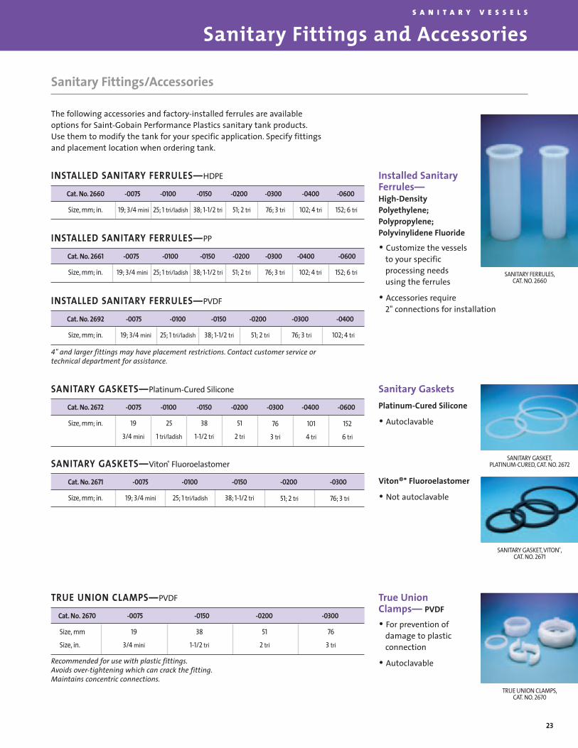
Sanitary Fittings/Accessories
The following accessories and factory-installed ferrules are availableoptions for Saint-Gobain Performance Plastics sanitary tank products.Use them to modify the tank for your specific application. Specify fittingsand placement location when ordering tank.
Installed SanitaryFerrules— High-DensityPolyethylene;Polypropylene;Polyvinylidene Fluoride
• Customize the vesselsto your specific processing needs using the ferrules
• Accessories require 2" connections for installation
Sanitary GasketsPlatinum-Cured Silicone
• Autoclavable
Viton®* Fluoroelastomer
• Not autoclavable
True Union Clamps— PVDF
• For prevention of damage to plastic connection
• Autoclavable
SANITARY FERRULES,CAT. NO. 2660
4" and larger fittings may have placement restrictions. Contact customer service or technical department for assistance.
Cat. No. 2671 -0075 -0100 -0150 -0200 -0300
19; 3/4 mini 25; 1 tri/ladish 38; 1-1/2 triSize, mm; in.
SANITARY GASKETS—Viton® Fluoroelastomer
Recommended for use with plastic fittings.Avoids over-tightening which can crack the fitting.Maintains concentric connections.
Cat. No. 2660 -0075 -0100 -0150 -0200 -0300 -0400 -0600
19; 3/4 mini 25; 1 tri/ladish 38; 1-1/2 tri 51; 2 tri 76; 3 tri 102; 4 tri 152; 6 triSize, mm; in.
INSTALLED SANITARY FERRULES—HDPE
19; 3/4 mini 25; 1 tri/ladish 38; 1-1/2 tri 51; 2 tri 76; 3 tri 102; 4 tri 152; 6 tri
Cat. No. 2661 -0075 -0100 -0150 -0200 -0300 -0400 -0600
Size, mm; in.
INSTALLED SANITARY FERRULES—PP
19; 3/4 mini 25; 1 tri/ladish 38; 1-1/2 tri 51; 2 tri 76; 3 tri 102; 4 tri
Cat. No. 2692 -0075 -0100 -0150 -0200 -0300 -0400
Size, mm; in.
INSTALLED SANITARY FERRULES—PVDF
SANITARY GASKET, VITON®,CAT. NO. 2671
SANITARY GASKET,PLATINUM-CURED, CAT. NO. 2672
TRUE UNION CLAMPS,CAT. NO. 2670
Cat. No. 2670 -0075 -0150 -0200 -0300
19
3/4 mini
38
1-1/2 tri
51
2 tri
76
3 tri
Size, mm
Size, in.
TRUE UNION CLAMPS—PVDF

Sanitary Fittings and AccessoriesS A N I T A R Y V E S S E L S
24
Not recommended for use with plastic fittings
*Other sizes available.
HEAVY DUTY CLAMP,CAT. NO. 2685
Sanitary Fittings/Accessories
End Caps—Polypropylene
• Autoclavable, seals ferrule when not in use
Sight Caps—Polysulfone
• Autoclavable
• Allows visibility into vessel
Cat. No. 2665 -0075 -0150 -0200 -0300 -0400 -0600
19
3/4 mini
38
1-1/2 tri
51
2 tri
76
3 tri
102
4 tri
152
6 tri
Size, mm
Size, in.
END CAPS—Polypropylene
Cat. No. 2666 -0200- 0300
51; 2 tri 76; 3 triSize, mm; in.
SIGHT CAPS—Polysulfone*
ELBOW SWEEPS,CAT. NO. 2663
END AND SIGHT CAPS,CAT. NOS. 2665 AND 2666
Cat. No. 2669 -0001 -0002 -0004 -0005 -0006
19 x 38
3/4 mini x 1-1/2 tri
25 x 38
1 tri x 1-1/2 tri
51 x 38
2 tri x 1-1/2 tri
51 x 25
2 tri x 1 tri
51 x 76
2 tri x 3 tri
Size, mm
Size, in.
CONCENTRIC REDUCERS—Polypropylene*
Cat. No. 2662-0150 2663-0150
90°
38, 1-1/2 tri
45°
38, 1-1/2 tri
Angle
Size, mm, in.
ELBOW SWEEPS—Polypropylene*
Cat. No. 2685 -0150 -0200 -0300 -0400 -0600
38; 1-1/2 1; 2 76; 3 102; 4 152; 6Size, mm; in.
HEAVY DUTY CLAMP—Stainless Steel
Elbow Sweeps and ConcentricReducers—Polypropylene
• Autoclavable
Heavy Duty Clamps—Stainless Steel
• Spring-loaded clamps toassure tight, leakprooffluid connections
• Autoclavable

Sanitary Fittings and Accessories
25
S A N I T A R Y V E S S E L S
Sanitary Fittings/Accessories
Siphon TubesFor use on Saint-Gobain PerformancePlastics closed-dome bio tanks (Cat. No.2650) for easy fluid transfer using a peri-staltic or vacuum pump. This 3/4-inchmini-siphon tube (5/8-inch I.D.) has a 2-inch sanitary mount and connects tomount on a 2-inch (50-mm) sanitary fit-ting. Tubes are cut to appropriate lengthsfor the 20-, 30-, 55- and 100-gallon (75-, 115-,210- and 380-liter) tanks. Fittings must beinstalled on tank to use this product.Materials are non-cytotoxic, meet USP
Class VI and comply with 21 CFR 177.1520for food and beverage use.* Autoclavable.
Sanitary Process Vessel Siphon Tubes—Polypropylene
For product sampling, reagent introduc-tion and drainage. Removable siphon tubemounts to a 2-inch sanitary flange andextends into the bottom of cone. Rigid3/4-inch (19-mm) mini-tube is compatiblewith common sanitary connectors includ-ing sanitary adapters, Sani-Lock, true-union clamps, short bull tees and gaskets.
Siphon tube does notinterfere with lowerassembly during mixing.Complies with21 CFR 177.1520(c) 3.1 andUSP Class VI regulations. Non-cytotoxic.Tubes are cut to length.Autoclavable.
Cat. No. 2656 -0030 -0055 -0100 -0200
75; 20
51; 2
16; 5/8
25; 0.985
92; 36-1/3
115; 30
51; 2
16; 5/8
25; 0.985
103; 40-1/2
208; 55
51; 2
16; 5/8
25; 0.985
115; 43-1/3
378; 100 Sanitary
51; 2
16; 5/8
25; 0.985
135; 53
Capacity, liter; gallons
Mount, mm; in.
Tube I.D., mm; in.
Tube O.D., mm; in.
Tube Length, cm; in.
SIPHON TUBE
Cat. No. 2658 -0050 -0200
50; 13
51; 2
14; 9/16
19; 3/4
90; 35-1/4
3/4-in. mini
200; 53
51; 2
14; 9/16
19; 3/4
97; 38
3/4-in. mini
Capacity, liter; gallons
Mount, mm; in.
Tube I.D., mm; in.
Tube O.D., mm; in.
Tube Length, cm; in.
For use with sanitary connection
SANITARY PROCESS VESSEL SIPHON TUBE
*Polypropylene meets all food grade requirements except for use with Food Type IV A (water-in-oil emulsions) and Food Type V (low-moisture fats and oils). The food type definitions are listed in 21 CFR 176.170(c).
SIPHON TUBE

Sanitary Fittings and AccessoriesS A N I T A R Y V E S S E L S
26
Sanitary Fittings/Accessories
Rotary Spray JetAcetal With Stainless Steel Spray Inserts
For cleaning Closed-Dome Bio Tank andSanitary Process Vessel interiors. Mountsand fits through a 2-inch sanitary flange;easily removable. Provides minimum of300° spray pattern for complete cleaning.Must order Mounting Assembly (Cat. No.2678-0001) separately. Autoclavable.
Mounting Apparatus for Spray Jet NozzlePolysulfone
Mounting apparatus 2678-0001 permitsuse of Rotary Spray Jet (Cat. No. 2677-0001). Mounts to a 2-inch sanitary flange.Easily removable. Ends in a 3/4-inch miniflange. Cleans with tank/vessel lowerassembly in place. Autoclavable.
1-Inch Ladish Charging ElbowPolypropylene With 2-inch Sanitary Mount
When adding fluid, 2681-0001 elbowdeflects flow to side of container wall,minimizing foaming. Prevents altering of buffer pH solutions and protein degradation. Autoclavable.
Sani-Sampling DevicePolypropylene With 2-inch Sanitary Mount
Catalog No. 2680-0001. Polypropylenesample tube extends into upper 1/4 ofClosed-Dome Bio Tanks or SanitaryProcess Vessels. Uses PTFE Syringe Filterand 3-way Luer-Lok®* valve. Luer-Lok®
connections allow easy connection tosyringes and other micro tubing.Autoclavable.
Sani-Sampling Valve 3-Way, Polypropylene
Catalog No. 2683-0001. Three-way Luer-Lok® valve. Allows easy connectionto PTFE syringe filters or Sani-SamplingDevice (Cat. No. 2680-0001).Autoclavable.
APPARATUS FOR SPRAY JETNOZZLE, CAT. NO. 2678-0001
ROTARY SPRAY JET,CAT. NO. 2677-0001
SANI-SAMPLING DEVICE,CAT. NO. 2680-0001
1-INCH LADISH CHARGINGELBOW, CAT. NO. 2681-0001
Cat. No. 2677 -0001
20 to 30 psig.
6 to 7 gal./min.
Pressure
Flow Rate
ROTARY SPRAY JETAcetal with Stainless Steel Spray Inserts
Proper Placement and Autoclave Instructions
27
S A N I T A R Y V E S S E L S
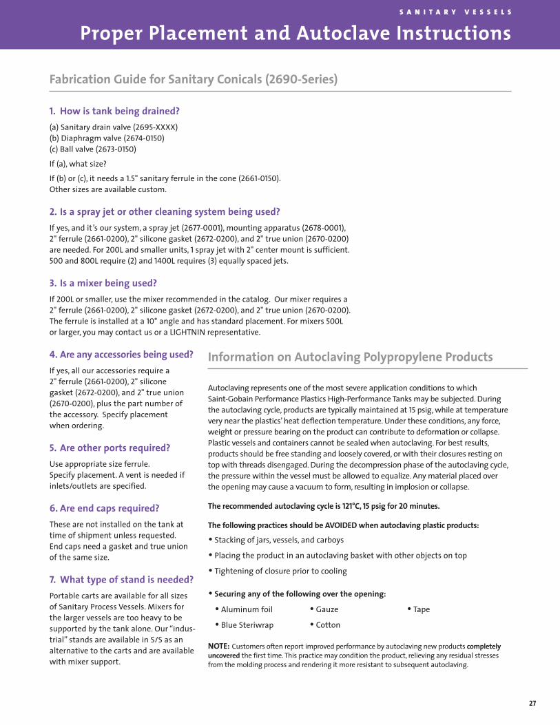
Fabrication Guide for Sanitary Conicals (2690-Series)
1. How is tank being drained?(a) Sanitary drain valve (2695-XXXX) (b) Diaphragm valve (2674-0150)(c) Ball valve (2673-0150)
If (a), what size?
If (b) or (c), it needs a 1.5" sanitary ferrule in the cone (2661-0150).Other sizes are available custom.
2. Is a spray jet or other cleaning system being used?If yes, and it’s our system, a spray jet (2677-0001), mounting apparatus (2678-0001),2" ferrule (2661-0200), 2" silicone gasket (2672-0200), and 2" true union (2670-0200)are needed. For 200L and smaller units, 1 spray jet with 2" center mount is sufficient.500 and 800L require (2) and 1400L requires (3) equally spaced jets.
3. Is a mixer being used?If 200L or smaller, use the mixer recommended in the catalog. Our mixer requires a2" ferrule (2661-0200), 2" silicone gasket (2672-0200), and 2" true union (2670-0200).The ferrule is installed at a 10° angle and has standard placement. For mixers 500L or larger, you may contact us or a LIGHTNIN representative.
4. Are any accessories being used?If yes, all our accessories require a 2" ferrule (2661-0200), 2" silicone gasket (2672-0200), and 2" true union (2670-0200), plus the part number of the accessory. Specify placementwhen ordering.
5. Are other ports required?Use appropriate size ferrule.Specify placement. A vent is needed ifinlets/outlets are specified.
6. Are end caps required?These are not installed on the tank attime of shipment unless requested.End caps need a gasket and true unionof the same size.
7. What type of stand is needed?Portable carts are available for all sizesof Sanitary Process Vessels. Mixers forthe larger vessels are too heavy to besupported by the tank alone. Our “indus-trial” stands are available in S/S as analternative to the carts and are availablewith mixer support.
Information on Autoclaving Polypropylene Products
Autoclaving represents one of the most severe application conditions to which Saint-Gobain Performance Plastics High-Performance Tanks may be subjected. Duringthe autoclaving cycle, products are typically maintained at 15 psig, while at temperaturevery near the plastics’ heat deflection temperature. Under these conditions, any force,weight or pressure bearing on the product can contribute to deformation or collapse.Plastic vessels and containers cannot be sealed when autoclaving. For best results,products should be free standing and loosely covered, or with their closures resting ontop with threads disengaged. During the decompression phase of the autoclaving cycle,the pressure within the vessel must be allowed to equalize. Any material placed over the opening may cause a vacuum to form, resulting in implosion or collapse.
The recommended autoclaving cycle is 121°C, 15 psig for 20 minutes.
The following practices should be AVOIDED when autoclaving plastic products:
• Stacking of jars, vessels, and carboys
• Placing the product in an autoclaving basket with other objects on top
• Tightening of closure prior to cooling
• Securing any of the following over the opening:
• Aluminum foil
• Blue Steriwrap
NOTE: Customers often report improved performance by autoclaving new products completelyuncovered the first time. This practice may condition the product, relieving any residual stressesfrom the molding process and rendering it more resistant to subsequent autoclaving.
• Gauze
• Cotton
• Tape

Putting It All TogetherS A N I T A R Y V E S S E L S
28
Portable Conical-BottomTank Stand
page 22
page 23
pages 24-27
Sanitary stands,page 21
Sanitary Process Vesselpages 19-21
Drain Valve
Sanitary Mixers
Fittings
pages 24-27
Accessories

General Guide to Bulk Storage Tanks
29
B U L K S T O R A G E T A N K S
A Complete Line of Rotationally Molded Bulk Storage Tanks
Saint-Gobain Performance Plastics bulk storage tanks, designed for a variety ofindoor and outdoor uses, are available in many sizes and shapes. They’re rotationallymolded of rugged cross-linked high-density polyethylene (XLPE) and high-densitypolyethylene (HDPE), which is a linear polyethylene. Rotomolding reduces molded-instresses, making the tanks durable and resistant to stress-cracking chemicals. Thisprocess also assures seamless, lightweight, uniform construction.
High Performance ResinsXLPE tanks are ideal for storing a wide range of corrosives, inorganic and organicchemicals and compounds, and boiler treatment chemicals. HDPE tanks can safelystore foodstuffs (resin complies with 21 CFR Regulation 177.1520. Refer to footnote 4on page 2), as well as many inorganic acids.
Plastics are Tough to BeatSaint-Gobain bulk storage tanks offer distinct advantages over steel/fiberglass prod-ucts. They are lighter in weight, more corrosion-resistant, translucent and easier tomaintain than steel tanks. Seamless construction eliminates leakage problems oftenassociated with fabricated tanks. Unlike fiberglass, plastic tanks do not wick.Saint-Gobain tanks are usually less expensive than either stainless steel or fiberglass.
There’s definitely a Saint-Gobain bulk storage tank to suit your requirements.Choose from vertical, conical-bottom or horizontal configurations. They come with avariety of accessories, too, including insulation, heat tracing, fill lines, and otheritems. A simple call to your Authorized Saint-Gobain Distributor is all it takes toorder one of these tanks, known industry-wide for quality and reliability.
Vertical Bulk Storage Tank
Sizes up to 12000 Gallons!Cover Options
Flat on Top Headfor Fittings
Tie-Down Lugs
Flats forBottom Fillings
Uniform WallThickness
Graduations
GenerousRadius
Choice of Five Diameters
PROPERTIES HIGH-DENSITY POLYETHYLENE (HDPE) CROSS-LINKED HIGH-DENSITY POLYETHYLENE (XLPE)
RESIN SELECTION GUIDE
ADVANTAGES
APPLICATIONS
NOT GENERALLY RECOMMENDED FOR
Chemical Resistance (general)Stress-Crack ResistanceMaximum Service TemperatureBrittleness TemperatureImpact ResistanceAbrasion ResistanceRigidityCleanabilityWeldability (hot gas)Food-Grade ResinColor
Very GoodGood
150°F / 65°C-94°F / -70°C
GoodGoodGood
Very GoodWeldable
YesWhite (Natural)
Very GoodExcellent
150°F / 65°C-180°F / -118°C
ExcellentGoodGood
Very GoodNot Weldable
NoGray (Pigmented)
• Rigid• Hard, Smooth Finish• Easy-To-Clean
• Very Good ChemicalReistance
• UV Stabilized for OutdoorService
• Excellent Impact Resistance• High Stress-Crack Resistance• Suitable for Many Corrosives
Not Handled by FRP
• UV Stabilized for OutdoorService
• Less Expensive ThanStainless Steel orFiberglass
• Storage of Organic andInorganic Acids
• Water Treatment
• Dispensing of Laboratoryand PhotographicChemicals
• Storage of Wide Range ofCorrosives
• Storage of Organic andInorganic Chemicals andCompounds
• Metal Finishing/Plating• Chemical Processing
• Storage of Boiler TreatmentChemicals
• Water and Sewage Treatment• Bulk Chemical Storage• Storage of Caustics
• Strong Oxidizing Agents,Aromatic Hydrocarbons,Liquefied PetroleumGas, Solvents
• Halogenated-AliphaticHydrocarbons
• Strong Oxidizing Agents, Aromatic Hydrocarbons,Halogenated-Aliphatic Hydrocarbons, LiquefiedPetroleum Gas, Solvents

30
Vertical Bulk Storage TanksB U L K S T O R A G E T A N K S
Vertical Bulk Storage Tank Features
Saint-Gobain Performance Plastics vertical bulk storage tanks have a number of unique features.The entire line offers:
• Sizes ranging from 550 gallons to12,000 gallons
• Choice of two resins (XLPE, HDPE) andtwo specific gravities (1.5, 1.9) at 73°F
• Circular top head flat for fittings(excluding 550-gallon size)
• Several cover options
• FOB, Garrett, Indiana 46738
• Seamless construction
• Mounting flats on the bottom portionof the tank (up to 4,000 gallons)
• Tie-down lugs
• Translucent*; observable liquid level
• Molded-in graduations up to 4,000gallons (90 inch diameter excluded)
• ASTM D 1998-96 (available at an additional cost)
• XLPE Tanks are gray, HDPE tanks are natural
Saint-Gobain Performance Plastics verticalstorage tanks have flat bottoms for easy installation. Smaller tanks (550-1550gallons) incorporate narrow-diameterdesign for space-saving bulk storage. Thismakes them economical for in-plant use.
Tanks are engineered for tough applications. They provide excellentlow-temperature impact resistance andare UV stabilized for outdoor use.
On request, Saint-Gobain PerformancePlastics will hydrostatically test your bulk storage tanks. Contact Saint-GobainPerformance Plastics for details.
Fittings and other accessories can beadded as specified to meet your requirements. Options are found onpages 34 and 35.
NOTE: All dimensions noted on tank drawingsare nominal. Vertical tanks do not include fittings, which must be ordered separately.Covers are included.
Insulation, Heat Tracing and Fill Lines AvailableInsulation — Permanent factory-appliedinsulation is 2 inches thick and consistsof 1.8 lbs-per-cubic-foot-density, non-
CFC containing urethane foam with amastic coating.
Heat Tracing — Heater package consistsof 115 Volt, dual-controlled thermostatsenclosed in a fiberglass housing.
Securely mounted to tanks, heaters provide a 50°F Delta T or a 75°F Delta T.
Fill Lines — This pipe, fitting and brack-et assembly allows you to fill storagetanks from an exterior inlet location.
Tank Size Graduations D & H Specific Cat. No. and Cat. No. and Wall Thickness Approx. Weight Standard Cover(gallons) (gallons) (in.) Gravity Size Code Size Code (in.) (lbs.) (in.)
HDPEXLPE
550
850
1100
1550
2000
2500
3000
3000
4000
4000
5500
6500
8000
10000
12000
50
100
100
100
250
250
250
N/A
250
N/A
N/A
N/A
N/A
N/A
N/A
48 x 84
64 x 74
64 x 93
64 x 127
96 x 83
96 x 99
96 x 116
90 x 126
96 x 145
90 x 162
120 x 134
120 x 155
143 x 138
143 x 168
143 x 198
1.51.91.51.91.51.91.51.91.51.91.51.91.51.91.51.91.51.91.51.91.51.91.51.91.51.91.51.91.51.9
N/A0.250.250.280.310.370.340.410.310.440.380.500.440.560.440.560.560.810.560.810.580.730.690.870.700.890.891.131.071.36
N/A140150170190220280415320445430625620800620800850110085011001100160014001900220028003000340038004400
N/A1616161616161616161616212121212121212121212121212121212121
N/A51309-055051305-085051309-085051305-110051309-110051305-155051309-155051305-200051309-200051305-250051309-250051305-300051309-300051305-309051309-309051305-400051309-400051305-409051309-409051305-550051309-550051305-650051309-650051305-800051309-800051305-910051309-910051305-920051309-9200
N/A51109-055051105-085051109-085051105-110051109-110051105-155051109-155051105-200051109-200051105-250051109-250051105-300051109-300051105-309051109-309051105-400051109-400051105-409051109-409051105-550051109-550051105-650051109-650051105-800051109-800051105-910051109-910051105-920051109-9200
90-inch diameter
MATERIAL
90-inch diameter
*Observation of liquid level depends on favorable light conditions, liquid color and a clean tank wall. Natural resin must be used, however,Saint-Gobain can not guarantee translucency. If liquid level observation is critical a sight gauge is recommended.**Wall thickness based on bottom side wall. N/A = Not Available

31
Vertical Bulk Storage TanksB U L K S T O R A G E T A N K S
NOTE: When factory-installed fittings are required, you must provide us with the catalog numberfor each fitting, catalog number for each tank and drawings (freehand is acceptable) of each tankwith its fitting(s).
*The minimum elevation for bottom outlet fittings is 9 inches (6 inches for 90-inch diameter tanks)up to 3 inch diameter fitting.
Tank Size INCHES(gallons) A B C D E F G
550
850
1100
1550
2000
2500
3000
3000
4000
4000
5500
6500
8000
10000
12000
48
64
64
64
96
96
96
90
96
90
120
120
143
143
143
84
74
93
127
83
99
116
126
145
162
134
155
138
168
198
72
62
79
113
66
82
99
109
128
145
123
144
120
150
180
N/A
6
6
6
12
12
12
9
12
9
14
14
14
14
14
11 x 12
11 x 12
11 x 12
11 x 12
13 x 16
13 x 16
13 x 16
7 x 9*
13 x 16
7 x 9*
N/A
N/A
N/A
N/A
N/A
9
16
16
16
18
18
18
15
18
15
30-1/2
30-1/2
42
42
42
26
26
26
26
32
32
32
30
32
30
32
32
32
32
32
VERTICAL TANKS
550-GALLON TANK
850-, 1100-, 1550-GALLON TANK2000-, 2500-, 3000-, 4000-
GALLON TANK3000-, 4000-GALLON TANK
(90-INCH DIAMETER)8000-, 10,000-, 12,000-GALLON TANK
5500-, 6500-GALLON TANK
Vertical Bulk Storage Tank Features
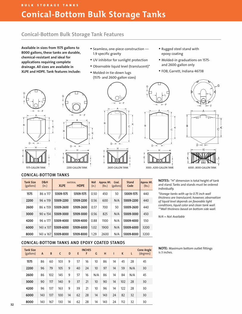
32
Conical-Bottom Bulk Storage TanksB U L K S T O R A G E T A N K S
Conical-Bottom Bulk Storage Tank Features
L
F
G
D
B
H
E
A
KC
I
F
H
E
A
KC
I
B
D
G
B
H
E
KC
I
F
A
DK
G
B
H
E
K
I
F
A
D
L
C
1575-GALLON TANK 2200-GALLON TANK 2600-GALLON TANK 3000-, 4200-GALLON TANK 6000-, 8000-GALLON TANK
Available in sizes from 1575 gallons to8000 gallons, these tanks are durable,chemical-resistant and ideal for applications requiring completedrainage. All sizes are available in XLPE and HDPE. Tank features include:
• Seamless, one-piece construction —1.9 specific gravity
• UV inhibitor for sunlight protection
• Observable liquid level (translucent)*
• Molded-in tie-down lugs (1575- and 2600-gallon sizes)
• Rugged steel stand with epoxy coating
• Molded-in graduations on 1575-and 2600-gallon only
• FOB, Garrett, Indiana 46738
NOTES: “H” dimension is total height of tankand stand. Tanks and stands must be orderedindividually.*Storage tanks with up to 0.75 inch wall thickness are translucent; however, observationof liquid level depends on favorable lightconditions, liquid color and clean tank wall.**Wall thickness based on bottom side wall.
N/A = Not Available
Tank Size D&H MATERIAL Wall Approx. Wt. Grad. Stand Approx. Wt.(gallons) (in.) XLPE HDPE (in.) (lbs.) (gallons) Code (lbs.)
1575
2200
2600
3000
4200
6000
8000
86 x 117
96 x 119
86 x 159
90 x 154
96 x 177
143 x 137
143 x 167
53309-1575
53309-2200
53309-2600
53309-3000
53309-4000
53309-6000
53309-8000
53109-1575
53109-2200
53109-2600
53109-3000
53109-4000
53109-6000
53109-8000
53009-1575
53009-2200
53009-2600
53009-3000
53009-4000
53009-6000
53009-8000
0.50
0.56
0.57
0.56
0.88
1.02
1.29
450
600
700
825
1100
1900
2600
50
N/A
50
N/A
N/A
N/A
N/A
440
440
440
450
550
3200
3200
CONICAL-BOTTOM TANKS
NOTE: Maximum bottom outlet fittings is 3 inches.
Tank Size INCHES Cone Angle(gallons) A B C D E F G H I K L (degrees)
1575
2200
2600
3000
4200
6000
8000
86
96
86
90
96
143
143
60
79
102
117
137
137
167
103
105
145
140
163
100
130
9
9
9
9
9
14
14
57
40
57
37
39
62
62
16
24
16
21
21
28
28
10
10
N/A
10
10
14
14
86
97
86
90
96
143
143
14
14
14
14
14
24
24
45
59
84
102
122
82
112
28
N/A
N/A
28
28
32
32
45
30
45
30
30
30
30
CONICAL-BOTTOM TANKS AND EPOXY COATED STANDS

33
Secondary Containment and Horizontal Leg TanksB U L K S T O R A G E T A N K S
SIDE VIEW (SQUARE BASIN)
TOP VIEW (SQUARE BASIN)
TYPICAL CONTAINMENT BASIN WITH TANK IN PLACE
Designed as durable barriers betweenstorage tanks and the environment,these secondary containment basinsfeature:
• UV-stabilized black HDPE for outdoor use
• Tapered walls for easy nesting
• Rib and steel spreader bar divides 218 inch length into two equal sections (1750- and 3500-gallon basins only)
Capacity L x W x H X Dimension Y Dimension Cat. No. Size Wall Thickness Weight(gallons) (in.) (in.) (in.) Code (in.) (lbs.)
375
495
950
1650
1750
3500
66 x 66x 24
69 x 69 x 28-1/2
83 x 83 x 45
99 x 99 x 53
218 x 108 x 21
218 x 108 x 40
59
62
69
85
94
94
59
62
69
85
203
203
59040
59040
59040
59040
59040
59040
-0375
-0495
-0950
-1650
-1750
-3500
.220
.250
.375
.375
.500
.500
100
125
320
400
580
1020
HDPE SECONDARY CONTAINER BASINS
HDPE Secondary Containment Basins
NOTE: Basin walls are tapered; be sure to reference outside tank dimensions. Contact your localregulatory body for approval before selecting secondary containment basins because of varyingrequirements.
Cost-efficient design simplifiesinstallation and saves money!Saint-Gobain Performance Plastics horizontal tanks with molded legs conveniently mount on flat surfaceswithout any additional support.Eliminating FRP saddles and steel cradles allows easy installation and provides significant cost reduction.Most fittings are factory installedbefore shipping*.
• Economical (no saddles or cradles)• Molded of translucent natural high-density
polyethylene (HDPE) for applications with food-grade resin requirements (i.e. potable water)
• Molded of translucent gray UV-stabilized XLPE for outdoor chemical storage
• Sturdy, self-supporting construction• Fittings available (See pages 34 and 35)• Up to 1.5 specific gravity service• Maximum operating
temperature to 150°F/65°C• FOB Garrett, Indiana 46738
Tank Size Cat. No. Cat. No. Size Specific Wall Thickness INCHES Approx. Wt.(gallons) HDPE XLPE Code Gravity (in.) A B C D E F† G (lbs.)
55
110
200
300
500
25100
25100
25100
25100
25100
25300
25300
25300
25300
25300
-0055
-0110
-0200
-0300
-0500
1.5
1.5
1.5
1.5
1.5
5/16
5/16
5/16
5/16
5/16
33
46
57-1/2
67-1/2
76
25-1/4
29
35
40-3/4
46-1/2
29-3/4
33-1/2
39-1/2
45
49-1/2
20-1/2
21
30
35-1/2
39
4-1/2
7
9
10-1/2
12
6
6
6
6
6
7
7
7
7
7
40
60
80
110
150
HORIZONTAL LEG TANKS
Saint-Gobain Performance Plastics Horizontal Leg Tanks
(TANK OPENING)
*Saint-Gobain recommends all fittings be factory installed.†Six-inch threaded closure.

34
Bulk Tank Fittings and AccessoriesB U L K S T O R A G E T A N K S
Fitting Material Cat. No. -0025 -0050 -0075 -0100 -0150 -0200 -0300 -0400 -0600(1/4") (1/2") (3/4") (1") (1-1/2") (2") (3") (4") (6")
Size Code and Availability (X)
86301
86501
86650
PVC
PP
316 SS
Bulkhead Fittings
(Plastic)
Install on Top-Dome Only
(316 StainlessSteel)
— X X X X X X X —
— X X X X X X X —
— — — X X X X X —
For Bulk Tanks
PVC, SS and PP bulkhead fittings are supplied with one EPDM gasket. PVC and PP two-part fittings screw together overa hole cut in the tank. Other gasket materials are available at added cost. Fittings provide female pipe thread.
86200PVC threaded with EPDM Gasket
and Encapsulated BoltHeads with 316 SS Bolts
— X X X X X X X X
86400PVDF threaded with Viton®*
Gasket and Bolt Headswith Hastelloy Bolts
— X X X X X — — —
Optional titanium or Hastelloy bolts with Viton®* encapsulated heads available.*4-inch and 6-inch fittings are available only for tanks with 96-inch diameter or larger.
INSTALLED FITTINGS, MECHANICAL
*Viton and TEFLON are registered trademarks of E.I. DuPont de Nemours and Company Inc.
These two-part fittings screw or bolt togetherover a hole cut in the tank. Other gasketmaterials are available at added cost.
Tank Fittings
Fittings can be factory-installed orshipped loose for on-site installation.Fitting prices and installation charges,where required, must be added to thecost of the tank. When ordering, alwayssupply drawings, and specify the type
of fitting required and exactly where it is to be installed. For open-top tankfittings and accessories, see pages 11-13.
Gaskets for Bulkhead Fittings
Fitting Resin Gasket Material No. of Gaskets
1
1
1
1
EPDM
EPDM
EPDM
VITON®
PP (Natural)
PVC
316 SS
PVDF
Flanged Fittings* with Free Bolts
(Encapsulated Heads)
86302PVC Body with Teflon®*Sealing Ring
Self-AligningBulkhead
Fitting
— — — X — X X — —
86320PVCFlange Adapter
with Nipple
— — — — X X X X —
86900
86651
86626
PVC
316 SS
PP
Siphon Tube without
Bulkhead Fitting
— — — — — X X — —
— — — — — X X — —
— — — — — X X — —
86304PVCU-Vent with Bulkhead Fitting
— — — — — X X X —

INSTALLED FITTINGS, MECHANICAL
35
Bulk Tank Fittings and AccessoriesB U L K S T O R A G E T A N K S
Fitting Material Cat. No. -0025 -0050 -0075 -0100 -0150 -0200 -0300 -0400 -0600(1/4") (1/2") (3/4") (1") (1-1/2") (2") (3") (4") (6")
Size Code and Availability (X)
76000-0002
PVCSight-GaugeAssembly forBulk StorageTanks Only
— — X — — — — — —
For Bulk Tanks
Consists of two PVC ball valves, fittings and clear PVC tubing (1-inch I.D.) installed close to top and bottom of tank unless otherwise specified. Contact Saint-Gobain Performance Plastics for single or triple valve design.
86303PVC — X X X X X — — —
Consists of PVC valves, fittings and translucent PE tubing (5/8 inch I.D. x 3/4 inch O.D.). Specify tubing length.
Female pipe threads with nipple on one end. These valves must be supported.
INSTALLED FITTINGS, MECHANICAL (continued)
For 550-, 850-, 1100-, 1550-, 2000- and 2500-gallon verticals and 1575- and 2600-gallon conical-bottom tanks.
Optional For 550-, 850-, 1100-, 1550-, 2000- and 2500-gallon verticals.Replacement for 3000- to 6,500-gallon vertical and 3000- and 4200-gallon conical-bottom tanks.
Bolted and gasketed manway cover available — contact Saint-Gobain Performance Plastics
Bulkhead Fitting Installation
For information on open-top tank fittingsand accessories, see pages 11-13.
Tank Diameter Minimums
Bulkhead Size Min. Tank I.D.(inches) (inches)
1/2
3/4
1
1-1/4
1-1/2
2
3
4
7.25
10.00
11.75
16.25
16.25
25.75
42.50
90.00
NOTE: Installation instructions for bulkheadfittings are available by contacting Saint-Gobain Performance Plastics.
True Union Ball Valves,
Threaded withOne Nipple
86780
86890
EPDM
VITON®
Gaskets for PP and PVC
Bulkhead Fittings*
— X X X X X X X —
— X X X X X X X —
86781
86891
EPDM
VITON®
For Stainless SteelBulkhead Fittings*
— X — X X X X X —
— X — X X X X X —
59000-0016HDPE16-inch Cover
59000-0021HDPE21-inch Threadedwith Cover
Lever Lock Device

Reliable, All-Plastic Corrosion-Resistant Units
Saint-Gobain Performance Plastics’Norton® Blowers are excellent choicesfor aggressive applications where metalblowers quickly corrode. Metal blowersrely on protective coatings, which devel-op pin holes and pores. Corrosive vaporsseep through and attack the metal,causing failure. Plastic blowers lastmuch longer because the material isinherently resistant to corrosion.
The smaller laboratory units have roundinlets and outlets. They are designed foruse in lab hoods and cabinets. They areavailable in direct drive with 2 motoroptions and 2 wheel options.
The industrial units have round inletsand square outlets and offer muchgreater capacity.
They are proven performers in toughindustrial applications, such as metalfinishing, chemical manufacturing,wastewater treatment, and chemicalstorage cabinets. In addition to theoptions for drives, motors, and wheels,a full line of transitions and flexibleconnectors is available for connection to ductwork.
Norton blowers are ordered by selectingthe right capacity, type of drive, motorand combination of plastic materials for your application. The “Four Steps toBlower Selection” on the followingpages will guide you.
Blower Features• Corrosion resistant
• Outlasts metal
• Quiet operation
• Choice of motors/materials
• Reinforced housing
• For indoor and outdoor† use
• Plastic transitions for easy attachmentto standard ducting
• Full line of replacement parts
If installing your own motor, note thatNorton blowers must not exceed thestated RPM of each blower (pages 40-42).
Industrial blowers feature round inletsand rectangular outlets. (For plastictransitions, see page 44)
NOTE: Blowers are supplied fully assembled in counterclockwise upblast position. Othercounterclockwise positions are available onrequest.*
†Protect motors and drives against weatherwhen blowers are roof-mounted.All outdoor vertical blower discharge ductsmust have weather hoods.
*Except Cat. No. 71300 Series Lab Blower—no bottom horizontal or down-blast positions.
Blowers for Lab and Industrial UseB L O W E R S
36
LAB-STYLE BLOWER
BELT DRIVE UNIT
DIRECT DRIVE UNIT

Blower Performance Curves
37
B L O W E R S
Saint-Gobain Performance Plastics belt-drive blowersare supplied with a 1:1 speed ratio. If you intend tochange your blower’s speed/capacity after installation,see the instructions supplied with all Saint-GobainPerformance Plastics belt-drive blowers.
Solid black lines show performance of 1:1 belt-drive blowers.
Broken black lines show belt-drive blower performancewhen speed-reducing sheaves are installed by customer.
Color shows area of most efficient blower operation.
NOTE: Saint-Gobain Performance Plastics blowers must notexceed 1725 rpm (1140 rpm on Size Code -0400)
Performance Curves for Belt-Drive Blowers
1725 RPM
1725 RPM1600 RPM
1140 RPM
580 RPM
800 RPM
1400 RPM
1140 RPM
680 RPM
1725 RPM
1500 RPM
1500 RPM
1140 RPM
680 RPM
1400 RPM
1600 RPM
1600 RPM
1400 RPM
1140 RPM
680 RPM
Size Code -0160 Size Code -0250
Size Code -0200
Size Code -0400
Size Code -0310

1140 RPM
1725 RPM
1140 RPM
1725 RPM
1140 RPM
1725 RPM
1140 RPM
1725 RPM
Blower Performance CurvesB L O W E R S
38
Lab Blowers
Industrial Blowers
8-IN. 1725 RPM
1725 RPM
1725 RPM
1725 RPM
1725 RPM
1140 RPM
1140 RPM
1140 RPM
1140 RPM
8-IN. 1140 RPM
5-1/2-IN. 1725 RPM
Size Code -0160 Size Code -0200
Size Code -0310
Size Code -0400
Size Code -0250
Solid black lines show performance of 1:1 belt-drive blowers.
Color shows area of most efficient blower operation.

Blower SelectionB L O W E R S
Four Steps to Blower Selection
1. Determine Air Flow and Static PressureAir Flow is measured in CFM, or Cubic Feet per Minute, and represents the volume ofthe area to be ventilated in one minute.
Static Pressure is measured in inches of water. It is the total resistance to incomingair flow from ducts, fittings, elbows, dampers, and other factors.
You can determine your existing unit’s capacity by checking the size and performancespecs. For new installations, the CFM and Static Pressure should be determined by amechanical engineer, HVAC contractor, ductwork manufacturer or other professional.
All our blowers are 60Hz.
GENERAL NOTES: Lab Blowers (sizes codes -0050 to -0150) have round inlets and outlets.Industrial blowers have round inlets and rectangular outlets (see dimension charts).All blowers used outdoors must be protected against weather.Blowers are supplied in counter-clockwise up-blast position. Other positions may be requested.
2. Select Direct or Belt Drive (if needed)
Some size blowers are only available in direct drive. Others can be belt driven as anoption. Consult page 35 for availability.
3. Motor Selection
Direct Drive Belt Drive
More compact
Single speed
Fewer moving parts
No field adjustment
Field adjustable to vary capacity
Flexible to process changes
Reduces stress on motor bearings
Economical in changing environments
4. Material Selection of WheelThe wheel’s chemical resistance takes priority because it is under centrifugal stress.
PVC Polypropylene
Good chemical resistance
Best at room temperature
Low cost
Very good general chemical resistance
Withstands higher temperatures, stresses
Potentially explosive fumes or dust
Motor Type Features Applications
Totally Enclosed Fan-Cooled (TEFC)
Explosion Proof (XP)
Housings have no direct openings
Internal fan cools motor
Insulated
UL-approved motor*
Insulated
Corrosive vapors
Dirty, damp or oily service
Forward curve blades
* UL and CSA for Class I, Group D or Class II, Group F and G.
39

Lab Blower Specifications These charts are arranged by increasing CFM. All lab blowers are 60Hz.
See the preceding “Four Steps To Blower Selection.”
Blower SpecificationsB L O W E R S
40
Industrial Blower Specifications These charts are arranged by increasing CFM. All lab blowers are 60Hz.
All industrial blowers have round inlets and rectangular outlets. See dimension charts later in this section for details.Plastic transitions are available to connect blowers to ductwork; refer to the last page in this section.
Drive Motor Material Replacement* RPM HP Power Voltage Approx. Shipping Cat. No.Enclosure Wheel/Housing Parts (Phase) (wt., lbs.) and Size Codes
SIZE CODES -0050/0075
1
1
PP/PVC
PP/PVC
Dir.
Dir.
XP
TEFC
1/6
1/6
1725
1725
115 (1)
115/208-230 (1)
51†
31†
71320-0075
71330-0050
140 to 225 CFM — 3/4 to 1/4 inch Static Pressure
Drive Motor Material Replacement* RPM HP Power Voltage Approx. Shipping Cat. No.Enclosure Wheel/Housing Parts (Phase) (wt., lbs.) and Size Codes
SIZE CODES -0050/0075
2
2
4
3
PP/FRP
PP/FRP
PVC/FRP
PVC/FRP
Dir.
Dir.
Dir.
Dir.
XP
TEFC
XP
TEFC
1/3
1/3
1/3
1/3
1140
1140
1140
1140
115/230 (1)
115/208-230 (1)
115/230 (1)
115/208-230 (1)
60†
60†
60†
60†
71420-0075
71430-0050
71520-0075
71530-0050
360 to 625 CFM — 3/4 to 1/4 inch Static Pressure
Drive Motor Material Replacement* RPM HP Power Voltage Approx. Shipping Cat. No.Enclosure Wheel/Housing Parts (Phase) (wt., lbs.) and Size Codes
SIZE CODES -0100/0150
2
2
3
3
PP/FRP
PP/FRP
PVC/FRP
PVC/FRP
Dir.
Dir.
Dir.
Dir.
XP
TEFC
XP
TEFC
1/3
1/3
1/3
1/3
1725
1725
1725
1725
115/230 (1)
115/208-230 (1)
115/230 (1)
115/208-230 (1)
60†
60†
60†
60†
71420-0150
71430-0100
71520-0150
71530-0100
710 to 1,025 CFM — 1-1/4 to 1/4 inch Static Pressure
Drive Motor Material Replacement* RPM HP Power Voltage Approx. Shipping Cat. No.Enclosure Wheel/Housing Parts (Phase) (wt., lbs.) and Size Codes
SIZE CODES -0160
5
5
6
6
5
5
6
6
PP/PVC
PP/PVC
PVC/PVC
PVC/PVC
PP/PVC
PP/PVC
PVC/PVC
PVC/PVC
Dir.
Dir.
Dir.
Dir.
Belt
Belt
Belt
Belt
XP
TEFC
XP
TEFC
XP
TEFC
XP
TEFC
1/3
1/3
1/3
1/3
1/3
1/3
1/3
1/3
1725
1725
1725
1725
1725
1725
1725
1725
208-230/460 (3)
208-230/460 (3)
208-230/460 (3)
208-230/460 (3)
208-230/460 (3)
208-230/460 (3)
208-230/460 (3)
208-230/460 (3)
58
60
58
60
135
130
137
132
72521-0160
72531-0160
72621-0160
72631-0160
72721-0160
72731-0160
72821-0160
72831-0160
355 to 500 CFM — 1-1/4 to 3/4 inch Static Pressure

Industrial Blower Specifications These charts are arranged by increasing CFM. All blowers are 60Hz.
Blower Specifications
41
B L O W E R S
Drive Motor Material Replacement* RPM HP Power Voltage Approx. Shipping Cat. No.Enclosure Wheel/Housing Parts (Phase) (wt., lbs.) and Size Codes
SIZE CODES -0200
PP/PVC
PP/PVC
PVC/PVC
PVC/PVC
Dir.
Dir.
Dir.
Dir.
XP
TEFC
XP
TEFC
3/4
3/4
3/4
3/4
1140
1140
1140
1140
208-230/460 (3)
208-230/460 (3)
208-230/460 (3)
208-230/460 (3)
125
113
128
116
72520-0200
72530-0200
72620-0200
72630-0200
650 to 800 CFM — 1 to 3/4 inch Static Pressure
Drive Motor Material Replacement* RPM HP Power Voltage Approx. Shipping Cat. No.Enclosure Wheel/Housing Parts (Phase) (wt., lbs.) and Size Codes
SIZE CODES -0250
PP/PVC
PP/PVC
PVC/PVC
PVC/PVC
Dir.
Dir.
Dir.
Dir.
XP
TEFC
XP
TEFC
1
1
1
1
1140
1140
1140
1140
230-460 (3)
208-230/460 (3)
230-460 (3)
208-230/460 (3)
135
122
138
125
72520-0250
72530-0250
72620-0250
72630-0250
960 to 1,210 CFM — 1-1/4 to 1 inch Static Pressure
Drive Motor Material Replacement* RPM HP Power Voltage Approx. Shipping Cat. No.Enclosure Wheel/Housing Parts (Phase) (wt., lbs.) and Size Codes
SIZE CODES -0200
PP/PVC
PP/PVC
PVC/PVC
PVC/PVC
PP/PVC
PP/PVC
PVC/PVC
PVC/PVC
Dir.
Dir.
Dir.
Dir.
Belt
Belt
Belt
Belt
XP
TEFC
XP
TEFC
XP
TEFC
XP
TEFC
3/4
3/4
3/4
3/4
3/4
3/4
3/4
3/4
1725
1725
1725
1725
1725
1725
1725
1725
208-230/460 (3)
208-230/460 (3)
208-230/460 (3)
208-230/460 (3)
208-230/460 (3)
208-230/460 (3)
208-230/460 (3)
208-230/460 (3)
128
122
116
116
138
138
140
150
72521-0200
72531-0200
72621-0200
72631-0200
72721-0200
72731-0200
72821-0200
72831-0200
730 to 1,100 CFM — 2 to 1-1/4 inch Static Pressure
Drive Motor Material Replacement* RPM HP Power Voltage Approx. Shipping Cat. No.Enclosure Wheel/Housing Parts (Phase) (wt., lbs.) and Size Codes
SIZE CODES -0250
PP/PVC
PP/PVC
PVC/PVC
PVC/PVC
PP/PVC
PP/PVC
PVC/PVC
PVC/PVC
Dir.
Dir.
Dir.
Dir.
Belt
Belt
Belt
Belt
XP
TEFC
XP
TEFC
XP
TEFC
XP
TEFC
1-1/2
1-1/2
1-1/2
1-1/2
1-1/2
1-1/2
1-1/2
1-1/2
1725
1725
1725
1725
1725
1725
1725
1725
208-230/460 (3)
208-230/460 (3)
208-230/460 (3)
208-230/460 (3)
208-230/460 (3)
208-230/460 (3)
208-230/460 (3)
208-230/460 (3)
140
124
140
130
160
155
220
190
72521-0250
72531-0250
72621-0250
72631-0250
72721-0250
72731-0250
72821-0250
72831-0250
1,110 to 1,910 CFM — 3 to 2 inch Static Pressure
7
7
8
8
7
7
8
8
7
7
8
8
9
9
10
10
9
9
10
10
9
9
10
10

Industrial Blower Specifications These charts are arranged by increasing CFM. All blowers are 60Hz.
Blower SpecificationsB L O W E R S
42
Drive Motor Material Replacement* RPM HP Power Voltage Approx. Shipping Cat. No.Enclosure Wheel/Housing Parts (Phase) (wt., lbs.) and Size Codes
SIZE CODES -0310
PP/PVC
PP/PVC
PVC/PVC
PVC/PVC
Dir.
Dir.
Dir.
Dir.
XP
TEFC
XP
TEFC
2
2
2
2
1140
1140
1140
1140
230/460 (3)
208-230/460 (3)
230/460 (3)
208-230/460 (3)
260
162
195
206
72520-0310
72530-0310
72620-0310
72630-0310
1,410 to 2,210 CFM — 1-1/4 to 1 inch Static Pressure
Drive Motor Material Replacement* RPM HP Power Voltage Approx. Shipping Cat. No.Enclosure Wheel/Housing Parts (Phase) (wt., lbs.) and Size Codes
SIZE CODES -0400
PP/PVC
PP/PVC
PVC/PVC
PVC/PVC
PP/PVC
PVC/PVC
Dir.
Dir.
Dir.
Dir.
Belt
Belt
XP
TEFC
XP
TEFC
TEFC
TEFC
5
5
5
5
5
5
1140
1140
1140
1140
1140
1140
230-460 (3)
208-230/460 (3)
230-460 (3)
208-230/460 (3)
208-230/460 (3)
208-230/460 (3)
270
285
300
295
370
380
72520-0400
72530-0400
72620-0400
72630-0400
72730-0400
72830-0400
3,350 to 5,000 CFM — 3 to 2 inch Static Pressure
Drive Motor Material Replacement* RPM HP Power Voltage Approx. Shipping Cat. No.Enclosure Wheel/Housing Parts (Phase) (wt., lbs.) and Size Codes
SIZE CODES -0310
PP/PVC
PP/PVC
PVC/PVC
PVC/PVC
PP/PVC
PP/PVC
PVC/PVC
PVC/PVC
Dir.
Dir.
Dir.
Dir.
Belt
Belt
Belt
Belt
XP
TEFC
XP
TEFC
XP
TEFC
XP
TEFC
5
5
5
5
5
5
5
5
1725
1725
1725
1725
1725
1725
1725
1725
30/460 (3)
208-230/460 (3)
230/460 (3)
208-230/460 (3)
230/460 (3)
208-230/460 (3)
230/460 (3)
208-230/460 (3)
220
152
225
172
277
237
283
284
72521-0310
72531-0310
72621-0310
72631-0310
72721-0310
72731-0310
72821-0310
72831-0310
2,900 to 3,640 CFM — 3-1/4 to 2-3/4 inch Static Pressure
Replacement No. PVC Wheel PP Wheel Shaft Extension Housing Back Plate Gasket
12
345678
9†
10
11121314
——
71509-000371509-0004
—72609-0160
—72609-0200
—
72609-0250**72629-0250†
—72609-0310
—72609-0400
71309-000271409-0002
——
72509-0160—
72509-0200—
72509-0250**72529-0250†
—
72509-0310—
72509-0400—
71309-003571409-0035/71409-0034*
IncludedIncludedIncludedIncludedIncludedIncludedIncluded
Included
IncludedIncludedIncludedIncluded
71309-000471409-0031
71409-003171409-003172509-001172509-001172509-001272509-001272509-0013
72509-0013
72509-001472509-001472509-001572509-0015
——
——
72509-001672509-001672509-001772509-001772509-0018
72509-0018
72509-001972509-001972509-002072509-0020
——
——
72509-003872509-003872509-003972509-003972509-0040
72509-0040
72509-004172509-004172509-004272509-0042
COMMON REPLACEMENT PARTS Match the replacement part number with the required item below.
*The shaft extension of the 71420-0150 blower was redesigned in 1986. For blowersup to and including serial number 71E463109, order shaft extension 71409-0034.For blowers with higher serial numbers, order shaft extension 71409-0035.
†For blowers up to and including serial number 72E56243—will accepta motor with 0.625 diameter shaft.
**For serial numbers above72E56243—will accept a motorwith 0.875 diameter shaft.
Call Saint-Gobain Performance Plastics for pricing on any housing, back plate or gasket.
11
11
12
12
13
13
14
14
13
14
11
11
12
12
11
11
12
12

Industrial INLET Standard Duct Size Type of Duct Joint
6-1/4 x 6-5/87-3/8 x 7-3/49-3/8 x 9-3/4
12-3/8 x 12-3/415-5/8 x 16
6791216
ButtsDucts insertsDucts inserts
ButtsButts
-0160-0200-0250-0310-0400
I.D. x O.D., IN. IN.
Cat. No. Size Code M N O P R S a b
-0160-0200-0250-0310-0400
16-1/220-3/824-1/429-3/439-3/4
9-1/1611-11/1613-9/1618-1/8
22-7/16
15-3/819-9/1622-13/1629-15/1636-13/16
5-11/167-11/168-1/4
10-5/812-3/16
5-13/167-1/2
8-7/1611-5/8
13-9/16
12-3/814-1/216-5/8
20-5/1624
810-1/1611-7/814-3/818-3/8
6-9/167-5/8
9-3/1612-3/1614-5/8
72520, 7252172530, 7253172620, 7262172630, 72631
Blower Specifications
43
B L O W E R S
*Size codes for these blowers are available with all catalog numbers.
Dir. = Direct Drive XP = Explosion-Proof TEFC = Totally Enclosed Fan-Cooled BELT = Belt Drive
Cat. No. A B C D E F G H J K
5-5/85-5/89-1/29-1/29-1/29-1/2
6-5/86-5/87-1/47-1/47-1/47-1/4
3-3/43-3/44-1/24-1/24-1/24-1/2
5-5/85-5/8
8888
99
10-1/210-1/210-1/210-1/2
77
7-1/47-1/47-1/47-1/4
14-1/2—19—
18-1/2—
—15-1/2
—19-1/2
—21-1/2
1111
15-1/815-1/815-1/815-1/8
4-1/24-1/2
8888
71330-005071320-007571430-, 71530-005071420-, 71520-007571430-, 71530-010071420-, 71520-0150
LAB BLOWER—Dimensions (Inches)
Cat. No. Size Code I.D. O.D. A B E G H H1 K
-0160-0200-0250-0310-0400
6-1/47-3/89-3/812-3/815-5/8
6-5/87-3/49-3/412-3/4
16
67-7/169-3/811-7/815-5/8
4-9/165-1/8
6-11/169-11/1611-7/8
1/21/21/21/23/4
13-1/414-1/215-3/417-1/4
23
1014
15-15/1620-15/1623-3/4
15-11/1621-11/1624-3/1631-9/1635-15/16
1010
11-1/213-1/2
18
72520, 7252172530, 7253172620, 7262172630, 72631
INDUSTRIAL BLOWERS WITH DIRECT DRIVE—Dimensions (Inches)INLET DIAMETER, IN.
Cat. No. Size Code N O P R S T a b
-0160-0200-0250-0310-0400
9-1/1611-11/1613-9/1618-1/8
22-7/16
15-3/819-9/1622-13/1629-15/1636-13/16
5-11/167-11/168-1/4
10-5/812-3/16
5-13/167-1/2
8-7/1611-5/8
13-9/16
16-3/816-3/819-1/8
22-13/1626-1/8
14-7/8 +/- 1-1/214-7/8 +/- 1-1/2
16 +/- 1-1/220-1/2 +/- 1-1/222-7/8 +/- 1-1/2
810-1/1611-7/814-3/818-3/8
6-9/167-5/8
9-3/1612-3/1614-5/8
72721, 7273072731, 7282172830, 72831
Cat. No. Size Code I.D. A B E G H H1 K M
-0160-0200-0250-0310-0400
6-5/87-3/49-3/412-3/4
16
67-7/169-3/811-7/815-5/8
4-9/165-1/8
6-11/169-11/1611-7/8
1/21/21/21/23/4
32-1/232-1/237-1/4
46-13/1654-9/16
1014
15-15/1620-15/1623-3/4
15-11/1621-11/1624-3/1631-9/1635-15/16
1010
11-1/213-1/2
18
22-1/422-1/426-3/432-1/441-7/8
72721, 7273072731, 7282172830, 72831
INDUSTRIAL BLOWERS WITH BELT DRIVE—Dimensions (Inches)INLET DIA., IN.
Lab INLET Standard Duct Size Type of Duct Joint
5-1/4 x 5-5/8Taper x 8
58
ButtsDucts slides over
71300 Series71400 and71500 Series
PVC DUCT TO BLOWER CONNECTIONYou may attach PVC duct to the blower inlet and transition, or use the Saint-Gobain flexible connection.
INLET
I.D. x O.D., IN. IN.
Industrial OUTLET Standard Duct Size Type of Duct Joint
6-1/4 x 6-5/88-1/4 x 8-5/8
10-3/8 x 10-3/413-5/8 x 1415-5/8 x 16
68101416
ButtsButtsButtsButtsButts
-0160-0200-0250-0310-0400
I.D. x O.D., IN. IN.
Lab OUTLET Standard Duct Size Type of Duct Joint
4 x 4-1/2Taper x 8
48
ButtsDucts slides over
71300 Series71400 and71500 Series
OUTLET
I.D. x O.D., IN. IN.

Transitions for Saint-Gobain Performance Plastics Industrial Blowers
Blower SpecificationsB L O W E R S
44
Cat. No. Size Code A B C D E F G Bolt Holes Duct O.D. Duct I.D.
8
10-1/16
11-7/8
14-3/8
18-3/8
6-9/16
7-5/8
9-3/16
12-3/16
14-5/8
5-7/8
7-11/16
9-1/2
11-3/16
15-3/4
4-3/8
5-5/16
6-3/4
9-5/8
12
11
11
12
12
13
6-5/8
8-5/8
10-3/4
14
16
6-1/4
8-1/4
10-3/8
13-5/8
15-5/8
14
18
22
22
22
72510
Fits Saint-Gobainindustrial blowers withthese size codes
-0160
-0200
-0250
-0310
-0400
• Connect rectangular blower outletto circular ductwork
• Permits fast, easy installation
• Rigid, welded PVC
• Flanges are drilled for blowers’bolt patterns
Transitions for Saint-Gobain Industrial Blowers
Connector “A”—I.D. Connector FitsCat. No. (Inches)
4-1/2
5-5/8
8
6-5/8
7-3/4
8-5/8
9-3/4
10-3/4
12-3/4
14
16
5-inch lab blower (outlet)
5-inch lab blower (inlet)
8-inch lab blower (inlet and outlet)
-0160 industrial blower (inlet and transition)
-0200 industrial blower (inlet)
-0200 industrial blower (transition)
-0250 industrial blower (inlet)
-0250 industrial blower (transition)
-0310 industrial blower (inlet)
-0310 industrial blower (transition)
-0400 industrial blower (inlet and transition)
72511-0050
72511-0055
72511-0100
72511-0160
72511-0200
72511-0205
72511-0250
72511-0255
72511-0310
72511-0315
72511-0400
• Easily fit inlets and outlets of laboratory blowers
• Stainless steel clamps (two) suppliedfor quick, easy installation
• Flexible PVC reduces excess vibration
• 6" Length
*Transitions are needed to convert the rectangular industrial blower outlet to a round duct.Must be ordered separately (Cat. No. 72510).
Lab Blower
Industrial Blower
Flexible Connector
Inlet
Outlet
Outlet
Duct
Duct
Duct
DuctInlet
Flexible Connector
TransitionRectangular
to Round

Technical Information
45
I N F O R M A T I O N
Technical Information
Food Grade ResinsThe resins used in Saint-GobainPerformance Plastics low-density andhigh-density polyethylene tanks complywith 21 CFR Regulation 177.1520. Thesetanks may be used with the followingkinds of food products:
• Nonacid, aqueous products; may con-tain salt or sugar or both (pH above 5.0)
• Dairy products and modifications:oil-in-water emulsions, high or low fat
• Moist bakery products with surfacecontaining no free fat or oil
• Dry solids with the surface containingno free fat or oil (no end-test required)and under all conditions of use asdescribed in Table 2 of 21 CFR Regulation177.1520 except for condition A—high-temperature heat sterilization (e.g., over 100°C)
Saint-Gobain Performance Plastics rotomolded polypropylene complies with21 CFR 177.1520 (c) 3.1 Regulation. The resinused in Saint-Gobain PVDF tanks complieswith 21 CFR Regulation 177.2510.
Plastic Products for BiotechnologyKnowing whether a plastic is toxic tocell cultures is critical to biotechnologyproduction. To test cytotoxicity, we sub-mitted representative molded resinsamples to an independent laboratory.
Samples were evaluated utilizing an MEMElution Procedure, utilizing a W.I. 38 orMRC-5 cell line. This is a standard cytotoxi-city test for pharmaceutical, medicaldevices and ophthalmic products (thoughit typically utilizes an L929 cell line.)
Dimensions and Wall ThicknessDimensional information contained inthis catalog is for reference only, for the
purpose of selecting product from thecatalog. There is no inference to tolerancesfor the listed approximate dimensions.For additional information, contactSaint-Gobain Performance Plastics.
Physical Service CapabilitiesMaximum service temperature listingsrefer to temperatures that should not beexceeded for the materials utilized in thespecific product line. Many factors, suchas chemical resistance, specific gravity,external stresses, product geometry,environment and many others affectthe suitability of a particular product.For additional information, contactSaint-Gobain Performance Plastics.
Environmental Stress-CrackingEnvironmental stress-cracking is thefailure of a plastic material in the presence of certain types of chemicals.This failure is not a result of chemicalattack. Simultaneous presence of threefactors causes stress-cracking:
• Tensile stress
• A stress-cracking agent
• Inherent susceptibility of the plasticto stress-cracking
Tensile StressesThese are set up during some moldingand fabrication processes. Environmentalconditions can add tensile stress,particularly if the tank is inadequatelysupported. Rotational molding createsparts that are virtually stress-free, sorotomolded tanks are less subject toenvironmental stress-cracking than fabricated tanks. Use of an FRP casingwill minimize tensile stress from addedload and further decrease the likelihoodof environmental stress-cracking.
Common Stress-Cracking AgentsDetergents, surface active chemicals,lubricants, oils, ultra-pure water and plating additives such as brightener and wetting agents.
Relatively small concentrations of stress-cracking agent may be sufficient to causecracking. (Stress cracking agents are iden-tified in the Chemical Resistance Chart.)
Susceptibility to Stress-Cracking This varies from plastic to plastic depend-ing on several characteristics of the molec-ular structure. Cross-linked high-densitypolyethylene is inherently more resistantto stress-cracking than either low- or high-density polyethylene. PVDF also has excel-lent stress-crack resistance.
Physical Service Capabilities Prolonged use of a plastic tank at temper-atures above ambient will shorten tanklife. Temperature effects are directlydependent on the characteristics of theplastic resin, specific gravity of tank con-tents, tank size and configuration, exteri-or support, and wall thickness of the tank.
Temperature cycling will shorten tank life.The impact resistance of most rotomold-ed tanks declines at low temperatures.Cross-linked high-density polyethyleneretains much of its impact resistance inlow temperature applications.
Ultraviolet (UV) StabilizationPlastics are attacked and deteriorate whenexposed to direct sunlight. When plastictanks absorb the sun’s ultraviolet light,the UV energy excites the polymers’chains,causing them to break. The effects arediscoloration, embrittlement and eventualcracking. Elevated temperatures and oxy-gen tend to accelerate the deterioration.Those Saint-Gobain Performance Plasticstanks listed as suitable for outdoor serviceare protected from UV attack by: coloringor pigmenting and/or adding internal sta-bilizers which preferentially absorb or dis-sipate the UV energy. Shading tanks fromthe sun will also prevent deterioration.
Tanks must be free to expand or contract;avoid excessive tension on the tank.
Resin Color Product
NaturalNaturalNaturalNatural
TanksTanksTanksTanks
High-Density Polyethylene (HDPE)Low-Density Polyethylene (LDPE)Polypropylene (PP)Polyvinylidene Fluoride (PVDF)
Resins Non-Toxic to Cell Cultures Contact Saint-Gobain for details, 800-451-0770.

Storage of Sodium Hypochlorite (NaOCl) in Polyethylene Tanks
Chemical StorageI N F O R M A T I O N
46
Some concerns have been expressed to Saint-Gobain Performance Plasticsregarding the storage of sodiumhypochlorite in polyethylene tanks.
Although polyethylene storage tankshave been used for storage of sodiumhypochlorite in the field for many years,there have been premature failures invery specific locales. We have reviewedall data available on the chemistry andtechnology of sodium hypochlorite storage, and we have the followinginformation:
Sodium hypochlorite (NaOCI) has nodirect effect on polyethylene. This hasbeen confirmed by the resin suppliers.It is suspected however, that contaminat-ed sodium hypochlorite does cause accelerated deterioration of polyethylene
tanks when stored over a period of time.Contamination such as trace metals, e.g.iron, copper, etc., which may be generat-ed from pumps, plumbing, fittings, etc.,or a poor quality (trace contamination)sodium hypochlorite shipment, maycause brittleness and cracking of thepolyethylene tanks.
We feel the main contributor to prematurefailure of polyethylene storage tanks iscontamination; the presence of sunlightcatalyzes/accelerates the rate of attack onpolyethylene. Saint-Gobain PerformancePlastics will only warrant tanks for thestorage of sodium hypochlorite if the following specifications are met:
• Heavy-walled tanks (bulk tanks, 1.9 specific gravity)
• Cross-linked polyethylene (XLPE)
We recommend the following steps to be taken by the end user:
• Flush/clean tanks periodically toremove contaminants and deposits
• Check quality of received NaOCI(chemical analysis/purity)
• Check plumbing, pumps and deliverymethods for materials of construction
We wish to emphasize that non-con-taminated sodium hypochlorite storagein polyethylene is an acceptable andcompatible combination. It appears thatcracking and premature tank failuresoccur only when sodium hypochlorite is contaminated with trace amounts ofmetals and subjected to sunlight.
A Guide To Using Saint-Gobain Performance Plastics Tanks With Most Common Chemicals
The resins used in Saint-GobainPerformance Plastics tanks are highlyresistant to many chemicals. This chartwill assist in the selection of tank materialfor use with common chemicals.Mechanical stress, high temperatures,and extended use tend to multiply theeffects of chemicals on the tank.
Such effects should be taken intoaccount when using Saint-GobainPerformance Plastics tanks for long-termchemical storage or with handling equipment. Under normal conditions,chemicals rated “S” may be safely han-dled by the plastic material. Chemicalsrated “U” are not recommended for storage in that particular material.
This chart applies to tank materials at temperatures from 70°F/21°C to140°F/60°C.
Storage of flammables in plastic tanksmust conform to local fire codes.
Mixing and/or dilution of certain chemicals in Saint-Gobain PerformancePlastics tanks can be potentially danger-ous. The reactive combination of different chemicals or compounds oftwo or more classes may cause an unde-sirable chemical effect or result in anincreased temperature which can affectchemical resistance. Small amounts ofcertain chemicals can drastically changethe characteristics of the blend. As temperature increases, resistance toattack decreases.
Chemicals can affect the strength, flexi-bility, surface appearance, color, dimen-sions or weight of plastics. The basicmodes of interaction which cause thesechanges are: (1) chemical attack on thepolymer chain, with resultant reductionin properties, including oxidation anddepolymerization; (2) physical change,including absorption of solvents, result-ing in softening and swelling of the
plastic; permeation of solvent throughthe plastic; dissolution in a solvent; andstress-cracking from the interaction of astress-cracking agent with molded-in orexternal stresses.
NOTE: The chemical resistance information in this chart is a general guide only. Becausemany factors can affect chemical resistance,you should test under your own conditions.If any doubt exists about specific applicationsof Saint-Gobain tanks, please contactSaint-Gobain Performance Plastics,460 Milltown Road, Bridgewater, NJ 08807or call (800) 435-3992, fax (908) 218-9009.
ATTENTION: Please be aware that, althoughseveral plastics may have excellent resistanceto various flammable or combustible chemicals or solvents, safety regulations forstorage or other local regulations may restrictstorage of these chemicals in tanks.

Chemical Resistance
47
I N F O R M A T I O N
LLDPE/LDPE/ 316Description % Conc. HDPE XLPE1 PP PVDF FRP PVC EPDM NEOPRENE VITON® STAINLESS
70°F 140°F 70°F 140°F 70°F 140°F 70°F 140°F 70°F 140°F 70°F 140°F 70°F 70°F 70°F 70°F
Acetaldehyde*AcetamideAcetic Acid*/**Acetic Acid*/**Acetic AnhydrideAcetone*†Acrylic Emulsions*AcrylonitrileAdipic AcidAlcohol:
Allyl*Amyl*/**Bensyl*Butyl*Diacetone*Ethyl*Hexyl*Isobutyl*Isopropyl*Methyl*Propyl*
Aluminum SaltsAluminum HydroxideAlums (All Types)Ammonia, Dry GasAmmonia, SolutionAmmonium SaltsAmyl Acetate*†Amyl ChlorideAniline*Antifreeze*/**Antimony ChlorideAqua Regia*Arsenic AcidBarium SaltsBenzadlehyde*Benzene*Benzene Sulfonic Acid*/**Benzoic AcidBlack Liquor2
BleachSee statement on NaOCI storage in Technical Data section
BoraxBoric AcidBromine GasBromine LiquidBromine Water†ButadieneButaneButanediol*Butyl Acetate†Butyl Alcohol*ButyleneButyric Acid
40
1-7980-100
Conc.10%Conc.10030
100100100
80
10
10All Conc.
10
Satd.Conc.Weak Conc.100
100100100
80
U U— —U UU UU UU UU U— —S S
U US S– –U U– –U U– –– –– –– –– –S S– –S SS SU US SU UU UU UU US SU US SS SU UU UU US S
U U
S SS SU UU UU U– –– –U UU UU U– –U U
U U— —S SS UU UU US U— —S S
S SS S– –S S– –S S– –– –S US SS SS SS SS SS SS SS SU UU UU US SS SU US SS SU UU US US S
S S
S SS SU UU UU U– –– –S SS US S– –– –
U US UU UU UU UU UU US US S
S SS US SS SS –S S– –– –S –S –S –S SS –S SS SS SS SU UU UU US US UU US SS SS UU US SS S
S S
S SS SU UU UU U– –S –U UU UU U– –S S
U US US SS U– UU U– –S US S
S SS SS SS SS US SS SS SS SS SS SS SS SS SU US SS SS US SS US SS US US SS SS US SS US SS SS S
S SS SS SS SS SS SS SS SS US SS US S
U U– –S SS UU UU US U– –S –
S SS S– –S S– –S S– –– –– –– –– –S S– –S SS SS US SS US U– –S SS SU U– –S S– –S US SS S
S S
S SS SS S– –– –– –– –– –S US S– –S U
U U– –S SU U– UU U– –U US S
U UU UU US –– –S SS SS –S SS SS SS SS SS SS SS SS SU UU UU US SS SU US SS SS S– –S S– –S SS –
S –– –U UU UU UU UU U– –U U– – S SU U
SSU–US–U–
–SUSS–SSSSSSSSSSSS–SS–U–SSU––SS
SS–––SU–––U–
USU–SU–U–
–SUSSSS–SSSS–SSSSU–US–U–SUU–U–U
SSUU––S–US––
USU–SU–U–
–SSSUSSSSSSSSS–S–U–SSSUSSUSSSSS
SSSSSSS––SSS
SSSSUS–SS
–SSSSSSSSSSUSSS–U–––S–USSSU––––
SS––USS–S–S–
See page 44 for chart and footnote legend.

Chemical ResistanceI N F O R M A T I O N
48
LLDPE/LDPE/ 316Description % Conc. HDPE XLPE1 PP PVDF FRP PVC EPDM NEOPRENE VITON® STAINLESS
70°F 140°F 70°F 140°F 70°F 140°F 70°F 140°F 70°F 140°F 70°F 140°F 70°F 70°F 70°F 70°F
Cadmium SaltsCalcium SaltsCalcium Hypochlorite**Calgon (sodium hexmeta phosphate)*Camphor OilCarbon Bisulfide* (disulfide)Carbon Dioxide, wet/dryCarbon MonoxideCarbon Tetrachloride†Carbonic AcidCastor Oil*Caustic Soda*Caustic Soda*Chlorine Gas, DryChlorine LiquidChlorine WaterChloroacetic Acid*Chlorobenzene*†Chloroform*†Chlorosulfonic Acid*Chrome AlumChromic AcidChromic Acid**Chromic Acid & 50%Sulfuric Acid*/**Citric Acid*Coconut Oil DerivativesCottonseed Oil*Cresol*Cresylic AcidCupric SaltsCuprous SaltsCyclohexaneCyclohexanone*Detergents*Developers, PhotographicDextrinDextroseDiazo SaltsDiesel FuelDiethylamineDiethylene Glycol*Dioctylphthalate*Disodium PhosphateEmulsions, Photographic*Epsom Salts (Magnesium Sulfate)Ethyl Acetate*Ethyl Alcohol*Ethyl BromideEthyl Chloride†Ethyl EtherEthylene ChlorideEthylene Dichloride*Ethylene Glycol**Ethylene Oxide
100
10Conc.100
Satd.100
Satd.2050
Satd.
Satd.Satd.
100100
12
S SS SS SU UU UU US SS SU US SU UU UU UU UU US UU UU UU UU US SS UU U
U UU US SU UU UU US SS SU UU UU US SS SS SS S– –U UU UU US SU US SU UU UU UU UU UU UU UU UU U
S SS SS SS SU UU US SS SU US SS SS SS SU UU US UU UU UU UU US SS SS U
S US SS SS SS UU US SS SU UU US SS SS SS SS SS U– –S SU US SS SS SU US SU UU UU UU UU US SU U
S SS SS SU UU UU US SS SU US SU US SS –U UU UU UU UU UU UU US SU UU U
U US SS SS SU UU US SS SU UU UU US SS SS SS SS US US UU US SU US SU US SU UU UU UU UU US US U
S SS SS SS S– –S US SS SS SS SS SS SU US SS SS SS US US UU US SS SS U
S US SS SS SS SS SS SS SS SS US SS SS SS S– –S SS U– –U US SS SS SU US SS SS SS US SS SS SS U
S SS SS S– –– –– –S SS SU US S– –– –S US S– –S SS US U– –– –– –– –– –
U US SS SS S– –– –– –– –S SS US SS SS S– –– –S SS SS SS U– –– –S S– –S U– –– –– –S S– –
– –S S– –– –– –U US SS SU US SS SS SS SU UU US SS UU UU UU US SS UU U
U US SS SS SU US US SS SU UU US SS SS SS SS SS UU U– –U US SS SS SU US SU UU UU UU UU US SU U
–S–––U––US–SSU––SUUUSUU
U––SUUSSU–––SS–UU––––S–––S–UUSU
SUUS–USSUSSSSUUUSUUUSUU
USSSUUSSU–S–SS–USSU––SUS–UUUUSU
SSS––SSSSSSS–S––USSUUSS
USSSSSSSS–S–SS–SU––S–S–SSS–SSSU
–S–SSUSSSSSSU–––USSUSSS
USS–SSUUSSSS–––SSSSS–SSSSSSSSS–
See page 44 for chart and footnote legend.

Chemical Resistance
49
I N F O R M A T I O N
LLDPE/LDPE/ 316Description % Conc. HDPE XLPE1 PP PVDF FRP PVC EPDM NEOPRENE VITON® STAINLESS
70°F 140°F 70°F 140°F 70°F 140°F 70°F 140°F 70°F 140°F 70°F 140°F 70°F 70°F 70°F 70°F
Fatty Acids*Ferric ChlorideFerric SaltsFerrous SaltsFish Solubles*Fluoboric AcidFluorine, DryFluosilicic AcidFluosilicic AcidFormaldehyde*/**Formic Acid*Freon 11Freon 113Freon 12FructoseFruit JuiceFruit Pulp*Fuel Oil*Gallic Acid*Gasoline*†GelatinGin*GlucoseGlue, P.V.A.Glycerol*Glycolic Acid*Glycols*/**Gold MonocyanideGrape JuiceGrape SugarGreaseHeptane*†Hexane*†HoneyHydraulic Oils (Petroleum)Hydraulic Oils (Synthetic)HydrazineHydrobromic AcidHydrochloric Acid4
Hydrochloric Acid4
Hydrocyanic AcidHydrofluoric AcidHydrofluoric AcidHydrofluosilicic AcidHydrofluosilicic AcidHydrogenHydrogen Chloride Gas, DryHydrogen PeroxideHydrogen PhosphideHydrogen SulfideHydrogen Sulfide, Aqueous Sol’nHydroquinoneHypochlorous AcidInks*IodineIodine (K Solution)
32Conc.40100
Satd.
Satd.
30
Satd.
372037Satd.507532Conc.100
30100
Conc.
Conc.
U US SS SS SU US SU US SS UU UU U– –– –S US SS SU UU UU UU US SU US S– –U UU UU US S– –S SU UU UU US SU UU U– –S SS SS SS SS U– –S SS US SS SS SS SS SS SS SS SU U– –U U
S SS SS SS SS SS SU US SS US US S– –– –S US SS SS SS US SS US SS US S– –S SS SS SS SS SS SS SS US US SS US US SS SS SS SS SS SS SS SS SS SS SS SS SS SS SS SS SS S– –U U
S US SS SS SU US SU US SS US US U– –– –S US SS SS SU US SU US –S SS SS –S SS SS US S– –S SS UU UU US SU UU U– –U US SS SS SS –S –S SS US SS SS U– –S SS US SS SS SU UU U
S SS SS SS S– –S SS US SS SS US SU US SS SS SS SS SS SS US SS SS SS SS SS SS US SS SS SS SS SS SS SS SS US US SS SS SS SS SS SS SS SS SS SS SS SS US SS SS SS US US S– –
S SS SS SS SS SS SU US US US US U– –– –– –S S– –S SS S– –S S– –– –S S– –S SS SS SS S– –S S– –S SS US SU UU U– –U U– –– –S –– –– –S US US SS SS S– –S S– –– –S S– –– –– –
S US SS SS SS SS SU US S– –U UU UU US SU US SS SS SS SS SS US S– –S S– –S US S– –S SS SS SS SS SU US SU UU UU US US SS SS SS UU US SS SS S– –S –S SS SS SS SS S– –U U– –
USSS–––––SSUU–SUUU–US–S–S––––––UUSU–S–SUSUU––S–S–SS–––U–
USSS–S–––SSSSSSUSSSUS–SSS––SS–UUUSSUS–SUSSU––S–S–SUU––U–
SSSS–SSSSSUUUUSSSSSSS–SSSS–SSSSSSSUSSSSSSSSSSS–S–SSSS–S–
SUU––US––S–SS–SSSS–SS–SSSSSSS–SSSSSSSUUU–UUS–S–S–SS––SU–
See page 44 for chart and footnote legend.

Chemical ResistanceI N F O R M A T I O N
50
LLDPE/LDPE/ 316Description % Conc. HDPE XLPE1 PP PVDF FRP PVC EPDM NEOPRENE VITON® STAINLESS
70°F 140°F 70°F 140°F 70°F 140°F 70°F 140°F 70°F 140°F 70°F 140°F 70°F 70°F 70°F 70°F
Isopropyl Alcohol*Isopropyle EtherIsooctaneJet Fuel (JP3, JP4, JP5)Kerosene*KetonesLactic Acid*Lard OilLatex*Lead AcetateLimeLinseed Oil*Lube Oil*Magnesium SaltsMaleic AcidMercuric SaltsMercurous SaltsMercuryMethyl AcetateMethyl Alcohol*Methyl BromideMethyl Butyl KetoneMethyl CellosolveMethyl Chloride*Methyl Isobutyl KetoneMethyl Ethyl Ketone*†Methyl MethacrylateMethyl Sulfuric Acid*MethylamineMethylene Chloride*MilkMineral OilsMolassesNaphtha*Naphthalene*Nickel SaltsNicotine*Nicotinic Acid*Nitric Acid**Nitric Acid**Nitric Acid**Nitric Acid**Nitrobenzene*Oils*
EssentialMineralVegetableLubricating
Oils and Fats*Oleic AcidOleumOrange ExtractOxalic AcidOzonePalmitic AcidParaffin
90
Satd.30
Satd.Satd.
100
100
100
Comm.
Dilute
0-2930-4950-6970-98100
Conc.
Satd.
U U– –– –– –U U– –U UU UU US S– –U UU US SS US SS SS S– –U UU U– –– –U U– –U U– –U U– –U US SU US SU UU US SU UU US SS UU UU UU U
– –– –– –– –U UU UU US SS UU US U– –
S U– –– –– –S U– –S US US SS SS SS US US SS US SS SS S– –S SU U– –– –U U– –U U– –S U– –U US SS US SU UU US SS SS SS SS UU UU UU U
– –S US US US US UU US SS UU US U– –
S U– –– –S US US –S UU US SS SS US SS US SS US SS SS S– –S SU UU US UU UU US U– –S U– –U US SS US SS US US SS SS SS UU UU UU UU U
– –– –– –– –S US UU US SS SU US US U
S SS US SS SS SU US US U– –S S– –S SS SS SS SS SS SS SS US SS SU US SS SU UU US US UU UU US SS SS SS SS SS SS US SS US UU UU US U
S SS SS SS SS SS SU US SS US SS SS S
– –– –– –– –S S– –S S– –– –S S– –S S– –S S– –S SS SS S– –S U– –– –– –– –– –– –– –S S– –– –– –S SS SS SS SS S– –– –S US U– –U U– –
– –– –– –– –S SS S– –– –S S– –S S– –
S U– –– –S US UU US –S U– –S SS US SS US SS SS SS SS SU US UU UU UU UU UU UU US –S UU UU US SS US SS UU US SS SS SS SU UU UU UU U
– –S US US US US UU U– –S US US US U
SUSUUSSU––S––SUSSSUSUSUUUSU–––S–UUU––––U––S
–––––UU––U–U
SUSUUUSUU–SS–SUSSSUSUUUUUUU––USS–UUS––UUUUU
USSSSUU–S–––
SUSSSUSSSSSSSSSSSSUSSUUSU–U–––SS–SSS––SSSUU
–SSSSSS–SSSS
SSSSSS–SS––SSSSU–SSSSSSSSS––S–SSSSSU––SSS–S
SSSSSS–––SSS
See page 44 for chart and footnote legend.

Chemical Resistance
51
I N F O R M A T I O N
LLDPE/LDPE/ 316Description % Conc. HDPE XLPE1 PP PVDF FRP PVC EPDM NEOPRENE VITON® STAINLESS
70°F 140°F 70°F 140°F 70°F 140°F 70°F 140°F 70°F 140°F 70°F 140°F 70°F 70°F 70°F 70°F
PentanePerchloric AcidPerchlorethylenePhenol Carbolic AcidPhosphoric AcidPhosphoric AcidPhosphorus PentoxidePhosphorus TrichloridePhotographic Solutions*Pickling Baths, Hydrochloric Acid*Pickling Baths, Sulfuric Acid*Pickling Baths, Sulfuric-Nitric*/**Picric Acid*Plating Solutions
Without Wetting Agents**Potassium SaltsPotassium Hydroxide*PropanePropyl Alcohol*Propylene Glycol*Pyridine*Pyrogallic AcidRayon Coagulating Bath*Selenic AcidShortening*Silicic AcidSilver SaltsSoap Solution*Soda AshSodium SaltsSodium Hexametaphosphate*Sodium Hydroxide*Sodium Hydroxide*Sodium Hypochlorite**
See NaOCI Storage statement, Pg 38.
Sour Crude*Stannic SaltsStannous SaltsStarch SolutionStearic Acid*Stoddard’s SolventStyrene MonomerSulfurSulfur ChlorideSulfur Dioxide**Sulfuric Acid3**Sulfuric Acid3**Sulfuric Acid3, 5**Sulfuric Acid3, 5**Sulfuric Acid, Fuming*3/**Sulfurous AcidTallowTannic Acid*Tanning Liquors*Tartaric AcidTetrachlorethane
10
55085100100
1
0-10
Any Conc.
10Conc.
Satd.100
0-4951-7475-9596-98
Conc.
Conc.
Satd.
– –S SU US US SS US UU US UU UU UU UU US U
S SU U– –U UU UU U– –U US SU US SS SU US SS SU UU UU UU U
U US SS SS SU U– –– –S UU US US SU UU UU UU US SS UU U– –S SU U
– –S SU US US SS SS U– –S SS SS SS US US U
S SS U– –S SS SS U– –S SS SS SS SS SS SS SS SS SS SS SS S
S US SS SS SS S– –– –S UU US US SS US UU UU US SS US SS SS SU U
– –S SU US SS SS US UU US SS SS SS US US U
S SS U– –S SS US SS US SS US SS SS SU US SS SU US SS –U U
S US SS SS SS SU U– –S UU US US SS UU U– –U US SS US S– –S SU U
– –S SS SS SS SS SS SS SS S– –– –– –S US U
S SS US S– –S SU US U– –S S– –S SS SS US SS S– –S SU US S
S SS SS SS SS SS SS SS SS US SS SS SS US UU US SS SS SS US SS S
– –S U– –– –S SS S– –– –S US SS SS US SS U
S SU U– –– –S S– –– –– –– –– –S SS SS SU US S– –– –S US S
S SS SS SS SS S– –– –– –– –S SS S– –– –– –– –S S– –S S– –S S– –
– –S UU US US US US –U US S– –– –U UU US U
S SS SS US U– –U US US SS S– –S SS SS SS SS S– –S SS SS –
S SS SS SS SU UU UU UU UU UU US SS SU UU UU US S– –S SS SS S– –
U–UUSS––––––U–
SSU––U–––––SSSS–SSS
–SS––UUSUS–UUUUU––––U
U–UUSS––S–––SS
SUSSUU–––––SSSSSSSU
––S–SUUSUSSUUUUU–S–SU
SSSSSS––––SSSS
SSSSSUS–––SSSSS–S–S
SSSSSSSSSSSSSSSSSS–SS
UUS–S––S–––––S
–USSSUS––––SSSSSSUU
–––SSSSSUSUUUU––SSS–S
See page 44 for chart and footnote legend.

Chemical ResistanceI N F O R M A T I O N
52
LLDPE/LDPE/ 316Description % Conc. HDPE XLPE1 PP PVDF FRP PVC EPDM NEOPRENE VITON® STAINLESS
70°F 140°F 70°F 140°F 70°F 140°F 70°F 140°F 70°F 140°F 70°F 140°F 70°F 70°F 70°F 70°F
Tetrahydrofuran*Thionyl ChlorideToluene*†Transformer Oil*TrichloroethyleneTrisodium PhosphateTurpentine*Urea*UrineVanilla Extract*Vinegar* (4-8% of Acetic Acid)
Water, Acid, MineWater, DistilledWater, DeionizedWater, FreshWater, SaltWetting Agents*Whiskey*White Liquor (Pulp Mill)White Water (Paper Mill)WInesXylene*†YeastZinc Salts
Satd.
Conc.
U UU UU UU UU US SU UU US SU UU U– –– –U US SS SU UU U– –– –S SU US SS S
U UU UU US UU US SU US SS SS SS SS SS SS US SS SS SS S– –– –S SU US SS S
U UU UU US UU US SU US SS SS SS SS -S SS SS SS SU US SS –S –S SU US SS S
U UU US S– –S US SS SS SS S– –S SS US SS SS SS SS SS SS U– –S SS SS SS S
– –– –S U– –S SS SU US SS S– –S S– –– –– –S SS SS S– –– –– –– –U US SS S
U UU UU UU UU US SU US US S– –S SS SS SS SS SS S– -–S SS S– –S SU U– –S S
U–U–USU–S–S–SSSS–S–––USS
U–U–USU–U–SUSSSS-SSS–USS
U–S–SSS–S–SSSSSS–SSSSSSS
SUSSS–SSS–SUSSSU–SSS–S––
Legend
S – Satisfactory
U – Unsatisfactory
- – No Test Data
* – These chemicals can cause stress-crackingof LLDPE, LDPE and HDPE under certainconditions. Rotomolded tanks are essen-tially stress-free and are not usuallyaffected by stress-cracking chemicals.However, these chemicals may affect theservice life of tanks with welded fittingsor seams, and unsupported tanks operat-ing under heavy loads. Use XLPE tankswhich have excellent environmentalstress-crack resistance.
** – Limited Warranty one year—see page 45.
+ – Permeation by this solvent may causesoftening, swelling and/or considerableloss of fluid in polyethylene tanks.
1 – XLPE exhibits high environmental stress-crack resistance, but available datais limited and tests are recommended forsevere conditions or chemicals not listed in this chart.
2 – Mostly satisfactory, but black liquor variesconsiderably in composition and tempera-ture. Field testing is recommended.
3 – Use of Sulfuric Acid may cause initialdiscoloration of interior tank wall surface due to oxidation.
– Refer to Chemical Resistance Chart forfittings and gaskets.
4 – Vapors from Hydrochloric Acid areextremely aggressive. When storing thisproduct, please make sure you haveinstalled an appropriate scrubbing sys-tem or specify a bolted and gasketedmanway cover with plastic bolts.Contact Saint-Gobain for pricing.
5 – For Bulk Storage of Sulfuric Acid concen-trations between 80%-95% please specifyXLPE Tanks designed for 2.2 specific gravity. We recommend this heavier walltank due to the stress-cracking and oxidiz-ing nature of this chemical. ContactSaint-Gobain for pricing on these tanks.
WARNING: Misuse of Saint-Gobain productscan be potentially dangerous. Before using this product, please refer to the appropriate Saint-Gobain catalogs/inserts and the variouswarnings, information, instructions and chemi-cal resistance chart. If any doubt exists about aspecific use of Saint-Gobain products, please
contact Technical Support, Saint-GobainPerformance Plastics, 1044 MacArthur Rd.,Reading, PA 19605 or call (800) 451-0770,fax (610) 376-4802.
MaterialsLLDPE—Linear Low-Density Polyethylene
LDPE—Low-Density Polyethylene
HDPE—High-Density Polyethylene
XLPE—Cross-Linked High-Density Polyethylene
PP—Polypropylene
PVDF—Polyvinylidene Fluoride
FRP—Fiberglass-Reinforced Polyester
PVC—Polyvinyl Chloride
EPDM—Ethylene Propylene Diene Monomer
NEOPRENE—A chloroprene polymer,synthetic rubber
VITON® —A fluoroelastomer, registered trademark of E.I. du Pont de Nemours andCompany, Inc.

Warranty and How to Order
53
I N F O R M A T I O N
How to Order Saint-Gobain Tanks and Accessories
Saint-Gobain Performance Plastics tanksand other products are available fromauthorized Saint-Gobain PerformancePlastics Distributors throughout the U.S.,Canada and Puerto Rico.
Always order by complete catalog num-ber (first four or five digits) and size code(last four digits). Be sure to include a briefproduct description and drawing showingthe location of installed fittings, wherenecessary. For example: one each 11100-0005 cylindrical tank and one each 93857-0050 nipple installed through side.Drawings are required when fittings areto be factory installed.
• Covers: Covers are included with tanks,and are sold as part of a complete pack-age—TANK/COVER COMBINATION.
• Freight: All shipments are F.O.B.Reading, Pennsylvania; Garrett, Indiana;or other distribution points.
• Applications: Saint-Gobain PerformancePlastics records application details forall bulk tank orders. This information
ensures correct usage of bulk tanks andsupports the Saint-Gobain warranty.Please submit the following with allbulk tank orders:
• Chemicals and concentration
• Service temperatures
• Specific gravity of contents
NOTE: Many Saint-Gobain PerformancePlastics Distributors stock Saint-GobainPerformance Plastics tanks. Please check withthe Saint-Gobain Performance PlasticsDistributor in your area for potential freightsavings.For assistance, call your nearest Saint-GobainPerformance Plastics Distributor or Saint-Gobain at (800) 451-0770.
• Delivery: Standard tanks are generallyavailable for prompt delivery fromstock. If your order is unusual in quanti-ty, size or fittings required, or if itinvolves a major installation, pleasecontact Saint-Gobain PerformancePlastics for delivery information.
• Return Goods Procedure: No materialwill be accepted for return withoutwritten authorization. Authorizedreturns must carry a Saint-GobainPerformance Plastics “AuthorizedReturn” label on the outside of the carton. These labels are available fromSaint-Gobain Performance Plastics.A certificate of safe handling is alsorequired. Specially fabricated or factory-modified tanks may not be returned forcredit.
NOTE: Plastic tanks which are subject tochemical, physical and/or thermal exposureshould be inspected on a routine basis for anysigns of leaking, cracking, discoloration,bulging or other deviations from the “as new”condition. The frequency of inspection will behighly dependent upon actual use conditions,as well as the age of the tank. Specific guide-lines must be determined by the user depend-ent upon actual use conditions. Saint-Gobaincannot provide specific guidelines due to thewide variety of applications and their effectson plastic tanks. Please consult this catalog orcontact Saint-Gobain for more information.

Saint-Gobain Performance PlasticsI-295 @ Harmony RoadMickleton, New Jersey 08056Tel: (800) 543-8823, (856) 423-6630 Fax: (856) 423-8182Roll Cover, Engineered Extrusions, Tankswww.bunnell-plastics.com
Saint-Gobain Performance Plastics150 Dey RoadWayne, New Jersey 07470-4669Tel: (973) 696-4700Fax: (973) 696-4056Chemware®
www.labpure.com
Saint-Gobain Performance Plastics700 Warner Blvd.Taunton, Massachusetts 02780Tel: (508) 823-7701 Fax: (508) 823-1438Specialty Extruded and Molded Silicone Productswww.biopharm.saint-gobain.com www.medical.saint-gobain.com
Saint-Gobain Performance PlasticsLa Mothe-aux-AulnaiesF-89120 Charny FranceTel: (33) 3-86-63-78-78Fax: (33) 3-86-63-77-77Silicone Products, Hose Assemblieswww.verneret.com
Saint-Gobain Performance PlasticsP.O. Box 1344, 11 Sichio DrivePoestenkill, New York 12140Tel: (518) 283-5963Fax: (518) 283-1418Specialty Closureswww.packagepure.com
Saint-Gobain Performance Plastics2316 West Wisconsin StreetPortage, Wisconsin 53901Tel: (800) 236-7600, (608) 742-8541Fax: (608) 742-3179Specialty Molded Silicone Componentswww.medical.saint-gobain.com
Manufacturing FacilitiesSaint-Gobain Performance Plastics2664 Gilchrist RoadAkron, Ohio 44305Tel: (800) 798-1554, (330) 798-9240Fax: (330) 798-6968TYGON® Brand Flexible Tubing,Chemfluor® Tubingwww.tygon.com www.biopharm.saint-gobain.comwww.medical.saint-gobain.com
Saint-Gobain Performance PlasticsP.O. Box 481, 3910 Industrial DriveBeaverton, Michigan 48612Tel: (888) 387-0067, (989) 435-9533Fax: (989) 453-2355TYGON® Brand Extruded Silicone and Molded Componentswww.biopharm.saint-gobain.comwww.medical.saint-gobain.comwww.industrialsilicone.com
Saint-Gobain Performance Plastics460 Milltown RoadBridgewater, New Jersey 08807Tel: (800) 435-3992, (908) 218-8888Fax: (908) 218-9009Flexible Components, SanitaryCouplers ReSeal® and PermaSeal®,Sani-Tech® Productswww.flexiblecomponents.com www.reseal.com www.tanks.saint-gobain.com
Saint-Gobain Performance PlasticsSuite 1203147 Chienkwo North RoadSection 2, Taipei, 104 TaiwanTel: (886) 2-2503-4201Fax: (886) 2-2503-4202
Saint-Gobain Performance Plastics50, Jalan PJS 11/20, Bandar Sunway,46150 Petaling Jaya, Selangor DE,MalaysiaTel: (603) 56364082 Fax: (603) 56364099
Saint-Gobain Performance Plastics3-7, Kojimachi, Chiyoda-kuTokyo 102-0083,JapanTel: (81) 3-3263-0285Fax: (81) 3-3263-0286
Saint-Gobain Performance PlasticsGrindwell LtdVia Old Madras RoadBangalore 560 049,IndiaTel: (91) 80-847-2900Fax: (91) 80-847-2905
Saint-Gobain Performance Plastics148 Newton RoadWetherill Park, NSW 2164AustraliaTel: (61) 2-9749-3598Fax: (61) 2-9643-2926
Saint-Gobain Performance PlasticsAv Independicia 703113280-000 Vinhedo-SPBrazilTel: (55) 19-3876-8153Fax: (55) 19-3876-8077
Saint-Gobain Performance Plastics460 Milltown RoadBridgewater, New Jersey 08807Tel: (800) 435-3992, (908) 218-8888Fax: (908) 218-9009
www.tanks.saint-gobain.com
FLS-3239-20M-1005-SGCS ©2005 Saint-Gobain Performance Plastics CorporationPrinted in U.S.A
Notice:Due to our continuous efforts to improve our products, the information contained in this document is subject to change without notice. Saint-Gobain Performance Plastics assumes no obligations or liability for any advice furnished by it, or for results obtained with respect to thoseproducts. All such advice is given and accepted at the buyers’ risk. Final determination of suitability of any information or product for the useto be contemplated is the sole responsibility of the user. This document contains proprietary information, which is protected by copyright, andmay not be reproduced in any form without written consent of Saint-Gobain Performance Plastics.
NOTE: Saint-Gobain Performance Plastics Corporation does not assume any responsibility or liability for any advice furnished by it, or for the performanceor results of any installation or use of the product(s) or of any final product into which the product(s) may be incorporated by the purchaser and/or user.The purchaser and/or user should perform its own tests to determine the suitability and fitness of the product(s) for the particular purpose desired in anygiven situation.
TYGON, ReSeal, Chemfluor, Sani-Tech, Chemware and Norton are registered trademarks.Viton is a trademark of E.I. du Pont de Nemours and Company.LuerLok is a registered trademark of Becton Dickinson.
Sales OfficesSaint-Gobain Performance Plastics1468 Kun Yang RoadMinhang Economic & TechnologicalDevelopment Zone,Shanghai, China 200245Tel: (86) 21-5472-1568Fax: (86) 21-5472-2378/5472-2379
Saint-Gobain Performance Plastics19801-5, Haramura, Suwa-gunNagano 391-0100,JapanTel: (81) 266-79-6400Fax: (81) 266-70-1001
Saint-Gobain Performance Plastics13th Floor, Donghsin Building141-28, Samsung-DongKangnam-Ku Soeul, 135-090KoreaTel: (82) 2-501-7361Fax: (82) 2-554-1550


