Page 1
1
CS-110
Automatic Changeover System
Operation and Maintenance Manual
The information contained in this manual was accurate at the time of printing. The most current versions of all Hydro
Instruments’ manuals can be found on our website www.hydroinstruments.com.
CS-110 Rev. 4/22/15
Page 2
2
Hydro Instruments
CS-110 Automatic Changeover System
Safety Precautions ......................................................................................................... 3
I. Overview ........................................................................................................................ 3
1. Contents
2. General Specifications
3. Functional Overview
II. Installation Instructions ............................................................................................... 5
1. Electrical Connections
2. General Description
III. Operation Instructions ................................................................................................. 7
1. Keypad Operation
2. Display & LED Description
3. Basic Operation
4. Modbus Communication
IV. Maintenance .................................................................................................................. 11
Figures:
1. Typical System Installation ......................................................................................... 4
2. CS-110 Internal Wiring Diagram ................................................................................ 6
3. CS-110 Display Screen Flow Chart ............................................................................ 8
4. Main Operating Screen Layout ................................................................................... 9
Table of Contents
Page 3
3
SAFETY PRECAUTIONS
GENERAL: Be sure to follow all applicable safety precautions when operating this equipment.
ELECTRICAL: The circuit board and incoming A/C power line carry the risk of shock and short circuit. Do
not touch any part of the circuit board or A/C power line unless you are certain that A/C power has been dis-
connected from the system.
1. Contents
This instruction manual describes the Series CS-110 automatic changeover controller and its use in an
automatic changeover system. See the circuit board diagram Figure 2.
2. General Specifications:
Dimensions: 301mm x 248mm x 128mm
Power Supply: 100-240 VAC 50/60 Hz
Power: 10W
Operating Temperature: -10° C to 50° C
Ambient Temperature: -10° C to 50° C
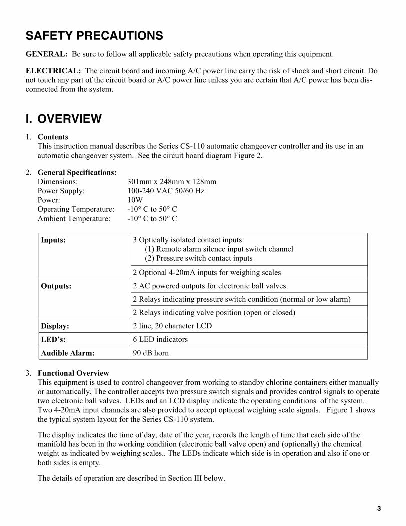
3. Functional Overview
This equipment is used to control changeover from working to standby chlorine containers either manually
or automatically. The controller accepts two pressure switch signals and provides control signals to operate
two electronic ball valves. LEDs and an LCD display indicate the operating conditions of the system.
Two 4-20mA input channels are also provided to accept optional weighing scale signals. Figure 1 shows
the typical system layout for the Series CS-110 system.
The display indicates the time of day, date of the year, records the length of time that each side of the
manifold has been in the working condition (electronic ball valve open) and (optionally) the chemical
weight as indicated by weighing scales.. The LEDs indicate which side is in operation and also if one or
both sides is empty.
The details of operation are described in Section III below.
I. OVERVIEW
Inputs: 3 Optically isolated contact inputs:
(1) Remote alarm silence input switch channel
(2) Pressure switch contact inputs
2 Optional 4-20mA inputs for weighing scales
Outputs: 2 AC powered outputs for electronic ball valves
2 Relays indicating pressure switch condition (normal or low alarm)
2 Relays indicating valve position (open or closed)
Display: 2 line, 20 character LCD
LED’s: 6 LED indicators
Audible Alarm: 90 dB horn
Page 4
4
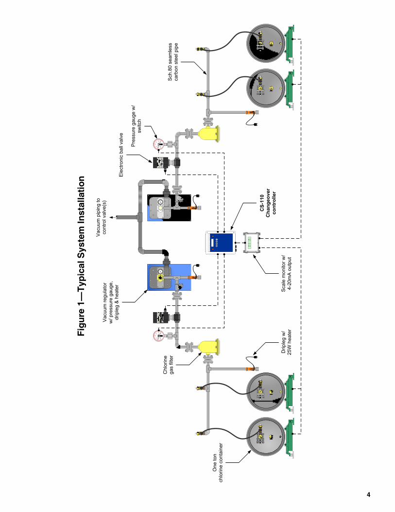
Fig
ure
1—
Ty
pic
al S
ys
tem
In
sta
llati
on
40
80
100
140 1
80
200
40
80
10
01
40 1
80
20
0
40
80
100
140 1
80
200
40
80
10
01
40 1
80
20
0
NET #1 = 1234
NET #2 = 5678
On
e to
n
ch
lorin
e c
on
tain
er
Ch
lorin
e
ga
s filt
er
Va
cu
um
re
gu
lato
r
w/ p
ressu
re g
au
ge
,
drip
leg
& h
ea
ter
Va
cu
um
pip
ing
to
co
ntr
ol va
lve
(s)
Ele
ctr
on
ic b
all
va
lve
Pre
ssu
re g
au
ge
w/
sw
itch
Sch
.80
se
am
less
ca
rbo
n s
tee
l p
ipe
Drip
leg
w/
25
W h
ea
ter
CS
-11
0
Ch
an
ge
ov
er
co
ntr
olle
r
Sca
le m
on
ito
r w
/
4-2
0m
A o
utp
ut
Page 5
5
II. INSTALLATION INSTRUCTIONS
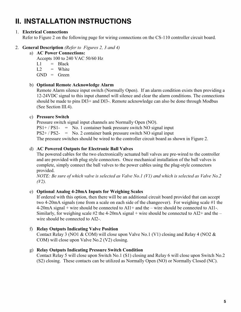
1. Electrical Connections
Refer to Figure 2 on the following page for wiring connections on the CS-110 controller circuit board.
2. General Description (Refer to Figures 2, 3 and 4)
a) AC Power Connections:
Accepts 100 to 240 VAC 50/60 Hz
L1 = Black
L2 = White
GND = Green
b) Optional Remote Acknowledge Alarm
Remote Alarm silence input switch (Normally Open). If an alarm condition exists then providing a
12-24VDC signal to this input channel will silence and clear the alarm conditions. The connections
should be made to pins DI3+ and DI3-. Remote acknowledge can also be done through Modbus
(See Section III.4).
c) Pressure Switch
Pressure switch signal input channels are Normally Open (NO).
PS1+ / PS1- = No. 1 container bank pressure switch NO signal input
PS2+ / PS2- = No. 2 container bank pressure switch NO signal input
The pressure switches should be wired to the controller circuit board as shown in Figure 2.
d) AC Powered Outputs for Electronic Ball Valves
The powered cables for the two electronically actuated ball valves are pre-wired to the controller
and are provided with plug style connectors. Once mechanical installation of the ball valves is
complete, simply connect the ball valves to the power cables using the plug-style connectors
provided.
NOTE: Be sure of which valve is selected as Valve No.1 (V1) and which is selected as Valve No.2
(V2).
e) Optional Analog 4-20mA Inputs for Weighing Scales
If ordered with this option, then there will be an additional circuit board provided that can accept
two 4-20mA signals (one from a scale on each side of the changeover). For weighing scale #1 the
4-20mA signal + wire should be connected to AI1+ and the – wire should be connected to AI1-.
Similarly, for weighing scale #2 the 4-20mA signal + wire should be connected to AI2+ and the –
wire should be connected to AI2-.
f) Relay Outputs Indicating Valve Position
Contact Relay 3 (NO1 & COM) will close upon Valve No.1 (V1) closing and Relay 4 (NO2 &
COM) will close upon Valve No.2 (V2) closing.
g) Relay Outputs Indicating Pressure Switch Condition
Contact Relay 5 will close upon Switch No.1 (S1) closing and Relay 6 will close upon Switch No.2
(S2) closing. These contacts can be utilized as Normally Open (NO) or Normally Closed (NC).
Page 6
6
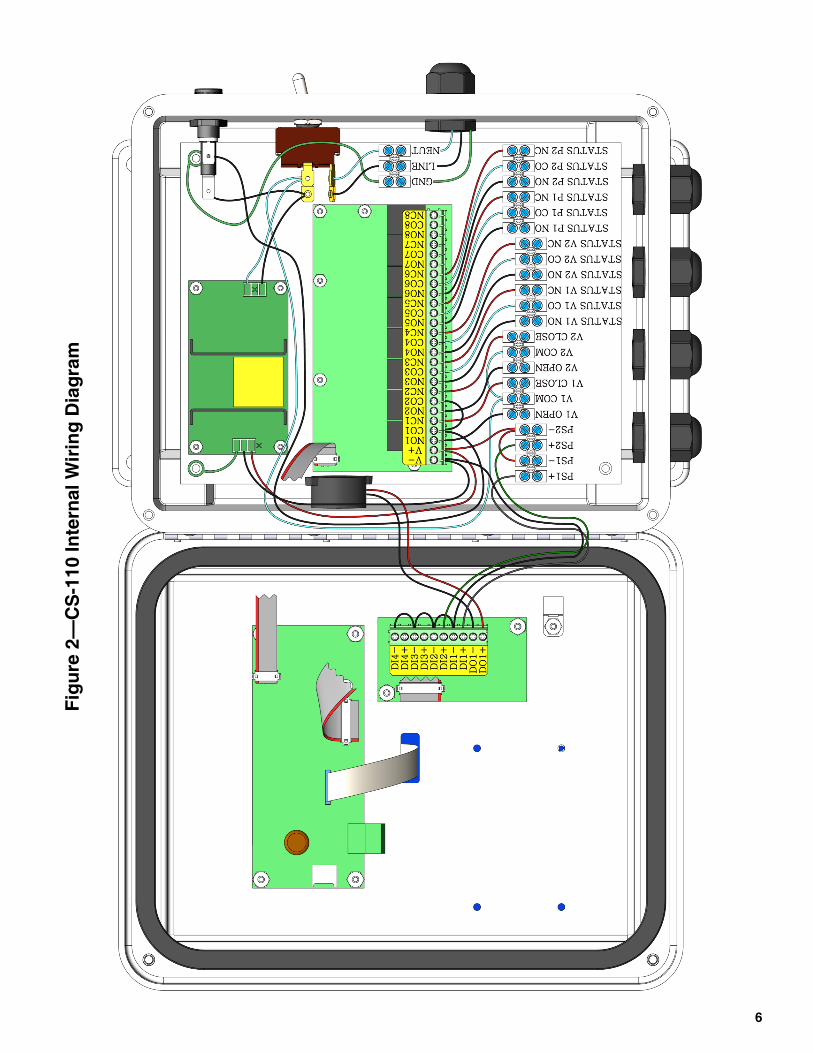
Fig
ure
2—
CS
-11
0 In
tern
al
Wir
ing
Dia
gra
m
Page 7
7
III. OPERATION INSTRUCTIONS
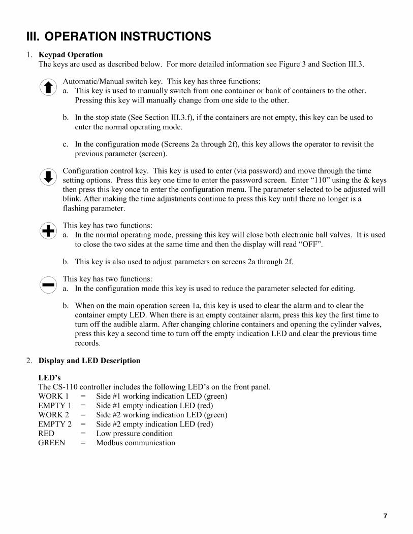
1. Keypad Operation
The keys are used as described below. For more detailed information see Figure 3 and Section III.3.
Automatic/Manual switch key. This key has three functions:
a. This key is used to manually switch from one container or bank of containers to the other.
Pressing this key will manually change from one side to the other.
b. In the stop state (See Section III.3.f), if the containers are not empty, this key can be used to
enter the normal operating mode.
c. In the configuration mode (Screens 2a through 2f), this key allows the operator to revisit the
previous parameter (screen).
Configuration control key. This key is used to enter (via password) and move through the time
setting options. Press this key one time to enter the password screen. Enter “110” using the & keys
then press this key once to enter the configuration menu. The parameter selected to be adjusted will
blink. After making the time adjustments continue to press this key until there no longer is a
flashing parameter.
This key has two functions:
a. In the normal operating mode, pressing this key will close both electronic ball valves. It is used
to close the two sides at the same time and then the display will read “OFF”.
b. This key is also used to adjust parameters on screens 2a through 2f.
This key has two functions:
a. In the configuration mode this key is used to reduce the parameter selected for editing.
b. When on the main operation screen 1a, this key is used to clear the alarm and to clear the
container empty LED. When there is an empty container alarm, press this key the first time to
turn off the audible alarm. After changing chlorine containers and opening the cylinder valves,
press this key a second time to turn off the empty indication LED and clear the previous time
records.
2. Display and LED Description
LED’s The CS-110 controller includes the following LED’s on the front panel.
WORK 1 = Side #1 working indication LED (green)
EMPTY 1 = Side #1 empty indication LED (red)
WORK 2 = Side #2 working indication LED (green)
EMPTY 2 = Side #2 empty indication LED (red)
RED = Low pressure condition
GREEN = Modbus communication
Page 8
8
Figure 3—Screen Flow Chart
V# ON HR:MN WGT
DOW MMM DD’YY TOD
Enter Password
110
Set Time And Date
No Yes
Change Time and Date
WED APR 15'15 14:25
Time and Date
Was Changed
Open Delay Time
15 secs
Scale Enable/Units
Off
Modbus Baud=9600
Node=1 Data=8/N/1
1a
1b
2a
2b
2c
2d
2e
2f
V# = V1 or V2
If scale function is disabled “WGT” will not be displayed.
Press [+] while “No” is flashing to skip to screen 2d
Adjust each parameter with [+] and [-] keys. See section
III.3.d for details.
See section III.3.g for explanation
Do not touch [+] or [-] on this screen unless scale hardware
is included. See section III.3.c for details.
Page 9
9
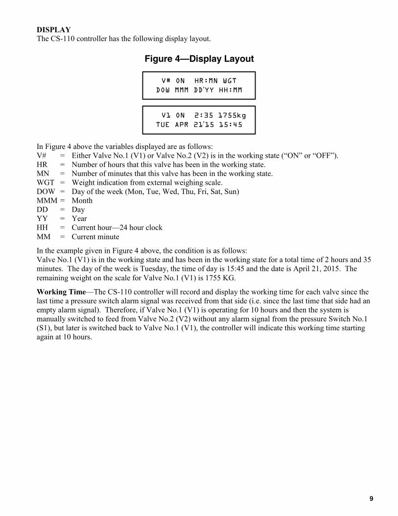
DISPLAY The CS-110 controller has the following display layout.
In Figure 4 above the variables displayed are as follows:
V# = Either Valve No.1 (V1) or Valve No.2 (V2) is in the working state (“ON” or “OFF”).
HR = Number of hours that this valve has been in the working state.
MN = Number of minutes that this valve has been in the working state.
WGT = Weight indication from external weighing scale.
DOW = Day of the week (Mon, Tue, Wed, Thu, Fri, Sat, Sun)
MMM = Month
DD = Day
YY = Year
HH = Current hour—24 hour clock
MM = Current minute
In the example given in Figure 4 above, the condition is as follows:
Valve No.1 (V1) is in the working state and has been in the working state for a total time of 2 hours and 35
minutes. The day of the week is Tuesday, the time of day is 15:45 and the date is April 21, 2015. The
remaining weight on the scale for Valve No.1 (V1) is 1755 KG.
Working Time—The CS-110 controller will record and display the working time for each valve since the
last time a pressure switch alarm signal was received from that side (i.e. since the last time that side had an
empty alarm signal). Therefore, if Valve No.1 (V1) is operating for 10 hours and then the system is
manually switched to feed from Valve No.2 (V2) without any alarm signal from the pressure Switch No.1
(S1), but later is switched back to Valve No.1 (V1), the controller will indicate this working time starting
again at 10 hours.
Figure 4—Display Layout
V# ON HR:MN WGT
DOW MMM DD’YY HH:MM
V1 ON 2:35 1755kg
TUE APR 21’15 15:45
Page 10
10
3. Basic Operation
a. Initial Power Up
When power is turned on, the CS-110 will automatically go to the operating mode with Valve No.1
(V1) open and in the working state. The WORK1 LED should be illuminated.
b. Time / Date Adjustments (Figures 3, Screen 2b)
The display should indicate the correct date, day of the week and time of day. If not, then these
parameters can all be adjusted. Press the key one time to enter the configuration mode (via
password: 110). Then press the key so that ‘Yes’ is flashing on screen 2a. Then press the key
to enter screen 2b. Adjust the time and date values on this screen.
c. Scale Setup (Figure 3, screen 2e)
NOTE: If the optional input for weighing scales was not included, do not touch the key while on
this screen. Should the key be accidentally pressed an alarm will sound and the CS-110 controller
will need to be turned off. The alarm will clear once power is restored.
If the CS-110 includes the hardware to support scales inputs, than navigate to screen 2e and select the
units desired for display (e.g. kg or Pd—for pounds).
d. Manual Changeover
In order to change from Valve No.1 (V1) to Valve No.2 (V2) in the working state, press the key one
time. The WORK 1 LED will go dark and the WORK 2 LED will illuminate when the controller
closes Valve No.1 (V1) after the delay time expires and opens Valve No.2 (V2).
e. Automatic Changeover
Under normal operation, one side should be in the working condition until the chlorine containers are
nearly empty. When the chlorine containers are nearly empty the pressure will suddenly fall. The
pressure switches should be set to alarm when the pressure falls below a user selected level (typically 1
to 2 kg/cm2). When the operating side receives the pressure switch signal, the alarm will sound, the
EMPTY LED will illuminate and the controller will close that valve and open the standby valve. The
scenario just described above is an automatic changeover. After a changeover has occurred, plant
personnel must press the key one time to silence the audible alarm. The empty container(s) must
also be replaced with new ones and connected to the manifold system again. After the containers have
been changed and the supply manifold pipe pressure restored the key must be pressed again to clear
the EMPTY alarm condition.
f. Stop Condition
If it is desired to close both sides of the system simultaneously then this feature should be used. During
normal operation (i.e. if not in the time adjustment mode) to close both valves press the key one
time. Both valves will close. In order to re-enter normal operation mode with Valve No.1 (V1) in the
working condition press the key one time. However, if there is an empty alarm condition present
you will not be able to enter the normal working condition.
g. Valve Open Delay Time (Figure 3, screen 2d)
There is a user adjustable delay time (typically set to 10-15 seconds) for the time from when the
working valve starts to close until the standby valve starts to open. This is done to allow the working
valve time to fully close before the standby valve starts to open. Enter the password and navigate to
screen 2d to adjust the delay time.
Page 11
11
4. Modbus Communication
Modbus RS-485 communication. The CS-110 is equipped for remote display and communication using
the Modbus RS-485 standard. To do this you must define the node, baud rate and parity of the system.
For more information on how to setup Modbus refer to the Modbus Installation and Instruction manual.
The Modbus Installation manual can be downloaded from the Hydro Instruments website
(www.hydroinstruments.com). Printed copies are available upon request.
When the system is working normally do not open the enclosure cover, do not touch the power supply or the
circuit board. If the equipment system is not working properly because of the influence of the outside factors,
you can turn off the power supply to reset the system and clear the problem. This will not influence the
recorded information.
IV. MAINTENANCE