CS1000 /-T270 ContaminationSensor Operating and maintenance instructions English (translation of original instructions) Valid from: - Firmware version C 3.10 - Hardware index F - Serial number: 0002S01515K0004000 Keep for future reference. Document No.: 4222780a
Transcript
CS1000 /-T270 ContaminationSensor
Operating and maintenance instructions English (translation of original instructions) Valid from: - Firmware version C 3.10 - Hardware index F - Serial number: 0002S01515K0004000 Keep for future reference.
Document No.: 4222780a
Imprint
Imprint
Publisher and responsible for the content: HYDAC FILTER SYSTEMS GMBH Postfach 1251 66273 Sulzbach / Saarland Germany Phone: +49 6897 509 01 Fax: +49 6897 509 9046 E-mail: [email protected] Homepage: www.hydac.com Court of Registration: Saarbrücken, HRB 17216 Executive director: Mathias Dieter,
Dipl.Kfm. Wolfgang Haering
Documentation Representative
Mr. Günter Harge c/o HYDAC International GmbH, Industriegebiet, 66280 Sulzbach / Saar Phone: +49 6897 509 1511 Fax: +49 6897 509 1394 E-mail: [email protected]
All rights reserved. No part of this work may be reproduced in any form (print, photocopy or by other means) or processed, duplicated or distributed using electronic systems without the written consent of the publisher. These documents have been created and inspected with the greatest care. However, errors cannot be ruled out completely. All details are subject to technical modifications. Technical specifications are subject to change without notice. The trademarks of other companies are exclusively used for the products of those companies.
Technical Support ........................................................................................ 7 Modifications to the Product ........................................................................ 7 Warranty ...................................................................................................... 7 Using the documentation ............................................................................. 7
Safety information ........................................................................................ 8
Hazard symbols ........................................................................................... 9 Signal words and their meaning in the safety information and instructions ................................................................................................ 10 Structure of the safety information and instructions ................................... 10 Observe regulatory information ................................................................. 10 Proper/Designated Use ............................................................................. 11 Improper Use or Use Deviating from Intended Use ................................... 11 Qualifications of personnel / target group .................................................. 13
Storing the sensor ...................................................................................... 15
Decoding the model code label ................................................................. 15
Checking the scope of delivery ................................................................. 16
Selecting connection type according to sensor type .................................. 21 Pipe or hose connection (type CS1xxx-x-x-x-x-0/-xxx) ........................... 21 Flange connection type (Type CS1xxx-x-x-x-x-1/-xxx) ........................... 21
Hydraulic installation of sensor .................................................................. 23 Selecting measurement location at the hydraulic systems ........................ 24
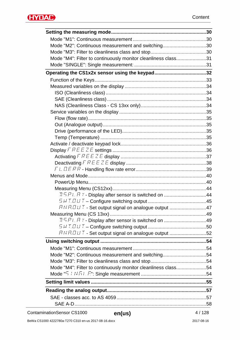
Setting the measuring mode ...................................................................... 30
Mode "M1": Continuous measurement ...................................................... 30 Mode "M2": Continuous measurement and switching................................ 30 Mode "M3": Filter to cleanliness class and stop ......................................... 30 Mode "M4": Filter to continuously monitor cleanliness class ...................... 31 Mode "SINGLE": Single measurement: ..................................................... 31
Operating the CS1x2x sensor using the keypad ...................................... 32
Function of the Keys .................................................................................. 33 Measured variables on the display ............................................................ 34
ISO (Cleanliness class) .......................................................................... 34 SAE (Cleanliness class) ......................................................................... 34 NAS (Cleanliness Class - CS 13xx only) ................................................ 34
Service variables on the display ................................................................ 35 Flow (flow rate) ....................................................................................... 35 Out (Analogue output) ............................................................................ 35 Drive (performance of the LED).............................................................. 35 Temp (Temperature) .............................................................................. 35
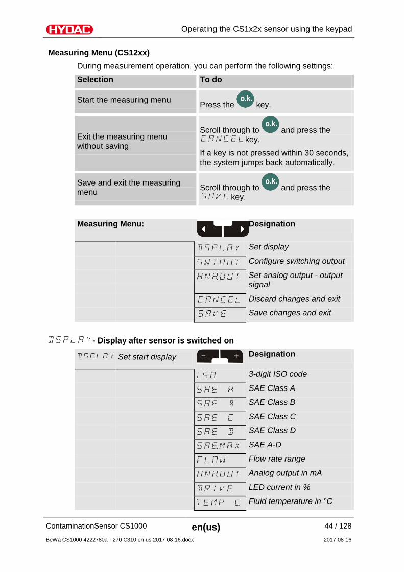
PowerUp Menu ....................................................................................... 40 Measuring Menu (CS12xx) ..................................................................... 44
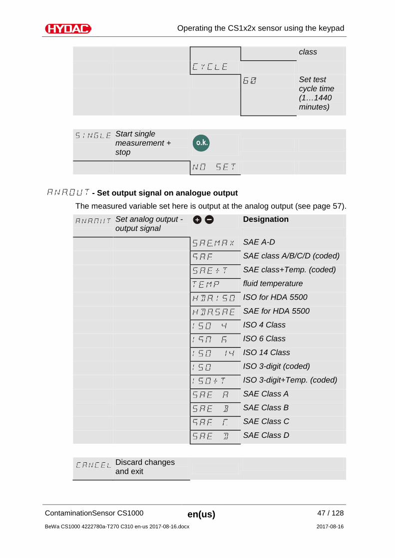
- Display after sensor is switched on ............................... 44 – Configure switching output ........................................... 45 - Set output signal on analogue output ........................... 47
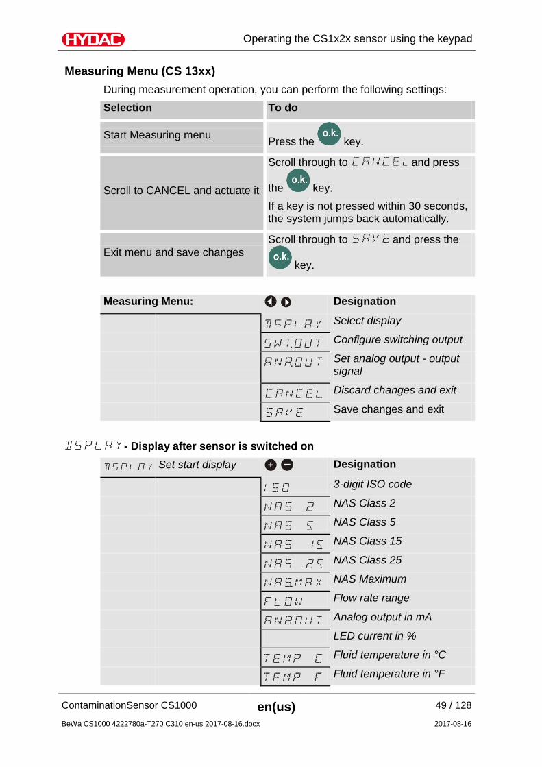
Measuring Menu (CS 13xx) ....................................................................... 49 - Display after sensor is switched on ............................... 49 – Configure switching output ........................................... 50 - Set output signal on analogue output ........................... 52
Using switching output .............................................................................. 54
Mode "M1": Continuous measurement ...................................................... 54 Mode "M2": Continuous measurement and switching................................ 54 Mode "M3": Filter to cleanliness class and stop ......................................... 54 Mode "M4": Filter to continuously monitor cleanliness class ...................... 54 Mode " ": Single measurement ................................................ 54
SAE classes A / B / C / D ....................................................................... 60 SAE A / SAE B / SAE C / SAE D ............................................................ 61 SAE + T .................................................................................................. 62 HDA.SAE – Analog signal SAE for HDA 5500 ....................................... 63 HDA.SAE Signal 1/2/3/4 ......................................................................... 64 HDA.SAE Signal 5 (Status) .................................................................... 64
ISO code according to ISO 4406:1999 ...................................................... 66 ISO 4 / ISO 6 / ISO 14 ............................................................................ 67 ISO Code, 3-digit .................................................................................... 68 ISO + T ................................................................................................... 69 HDA.ISO – Analog signal ISO for HDA 5500 ......................................... 70 HDA.ISO Signal 1/2/3/4 .......................................................................... 71 HDA.ISO Signal 5 (Status) ..................................................................... 72
ISOISO code signal acc. to ISO 4406:1987 (CS 13xx only) ...................... 74 ISO 2 / ISO 5 / ISO 15 ............................................................................ 75 ISO Code, 3-digit .................................................................................... 76 ISO + T ................................................................................................... 77 HDA.ISO – Analog signal ISO for HDA 5500 ......................................... 78 HDA.ISO Signal 1/2/3/4 .......................................................................... 79 HDA.ISO Signal 5 (Status) ..................................................................... 80
NAS 1638 - National Aerospace Standard (CS 13xx only) ........................ 82 - NAS Maximum ................................................................. 83
NAS classes (2 / 5 / 15 / 25) ................................................................... 84 NAS 2 / NAS 5 / NAS 15 / NAS 25 ......................................................... 85 NAS + T .................................................................................................. 86 HDA.NAS – Analog signal NAS for HDA 5500 ....................................... 87 HDA.NAS Signal 1/2/3/4 ........................................................................ 88 HDA.NAS Signal 5 (Status) .................................................................... 89
Fluid temperature TEMP............................................................................ 91
Status Messages ......................................................................................... 92
Status LED / Display .................................................................................. 92 Error messages ......................................................................................... 95 Exceptions Errors ...................................................................................... 96 Analog Output Error Signals ...................................................................... 98 Analog signal for HDA 5500 ...................................................................... 99
HDA Status Signal 5 Table ..................................................................... 99
Calibrating the sensor .............................................................................. 104 Cleaning the display / user interface ........................................................ 104
Decommissioning the sensor .................................................................. 104
Disposing of the sensor ........................................................................... 104
Spare Parts and Accessories .................................................................. 105
TECHNICAL DATA .................................................................................... 106
Finding Customer Service ....................................................................... 108 Germany .............................................................................................. 108 USA ...................................................................................................... 108 Australia ............................................................................................... 108 Brazil .................................................................................................... 109 China .................................................................................................... 109
Checking/resetting default settings .......................................................... 110 PowerUp Menu ..................................................................................... 110 Measuring menu ................................................................................... 110
Cleanliness class - ISO 4406:1999 ...................................................... 112 Table - ISO 4406 .................................................................................. 112 Overview of modifications - ISO4406:1987 <-> ISO4406:1999 ............ 113 Table - SAE AS 4059 ........................................................................... 115 Definition acc. to SAE ........................................................................... 116
Particle count (absolute) larger than a defined particle size .............. 116 Specifying a cleanliness code for each particle size ......................... 116 Specifying highest measured cleanliness class ................................ 116
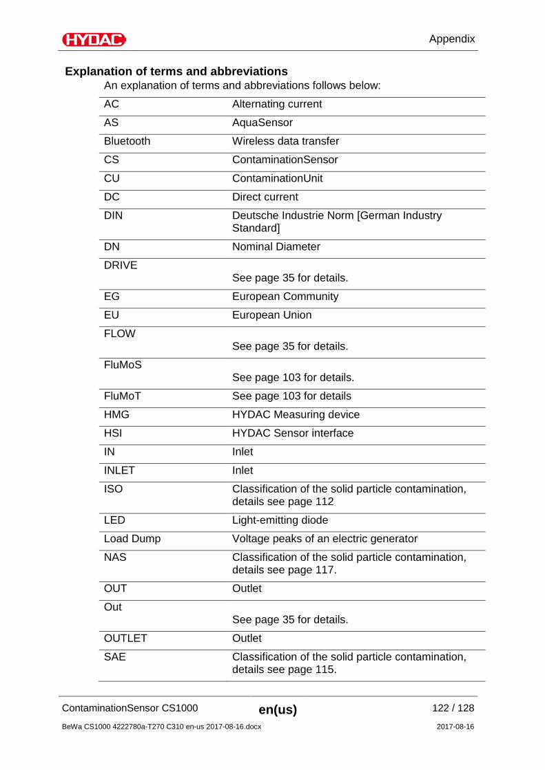
Cleanliness class - NAS 1638 .............................................................. 117 Glossary .................................................................................................. 118 - EGDeclaration of conformity .................................................................. 119 Glossary .................................................................................................. 121 Explanation of terms and abbreviations ................................................... 122 Index ........................................................................................................ 124
Preface
These operating instructions were made to the best of our knowledge. Nevertheless and despite the greatest care, it cannot be excluded that mistakes could have crept in. Therefore please understand that, in the absence of any provisions to the contrary hereinafter, our warranty and liability – for any legal reasons whatsoever – are excluded in respect of the
information in these operating instructions. In particular, we shall not be liable for lost profit or other financial loss. This exclusion of liability does not apply in cases of intent and gross negligence. Moreover, it does not apply to defects which have been deceitfully concealed or whose absence has been guaranteed, nor in cases of culpable harm to life, physical injury and damage to health. If we negligently breach any material contractual obligation, our liability shall be limited to foreseeable damage. Claims due to Product Liability shall remain unaffected.
Technical Support If you have any questions, suggestions, or encounter any problems of a technical nature, please don't hesitate to contact us. When contacting us, please always include the model code, serial no. and part no. of the product: Fax: +49 6897 509 9046 E-mail: [email protected]
Modifications to the Product We would like to point out that changes to the product (e.g. purchasing additional options, etc.) may mean that the information in the operating instructions is no longer applicable or adequate. After modification or repair work that affects the safety of the product has been carried out on components, the product may not be returned to operation until it has been checked and released by a HYDAC technician. Please notify us immediately of any modifications made to the product whether by you or a third party.
Warranty For the warranty provided by us, please refer to the terms of delivery of HYDAC FILTER SYSTEMS GMBH. You will find these under www.hydac.com -> Legal information.
Using the documentation
Note that the method described for locating specific information does not release you from your responsibility of carefully reading all these instructions prior to starting the unit up for the first time and at regular intervals in the future.
What do I want to know? I determine which topic I am looking for.
WHERE can I find the information I’m looking for? The document has a table of contents at the beginning. I select the chapter I'm looking for and the corresponding page number.
deHYDAC Filtertechnik GmbHBeWa 123456a de
Seite x
Produkt / Kapitel
200x-xx-xx
The documentation number with its index enables you to order another copy of the operating and maintenance instructions. The index is incremented every time the manual is revised or changed.
Safety information
The device was built according to the statutory provisions valid at the time of delivery and satisfies current safety requirements. Any residual hazards are indicated by safety information and instructions and are described in the operating instructions. Observe all safety and warning instructions attached to the unit. They must always be complete and legible. Do not operate the unit unless all the safety devices are present. Secure the hazardous areas which may arise between the unit and other equipment. Maintain the unit inspection intervals prescribed by law.
Document the results in an inspection certificate and keep it until the next inspection.
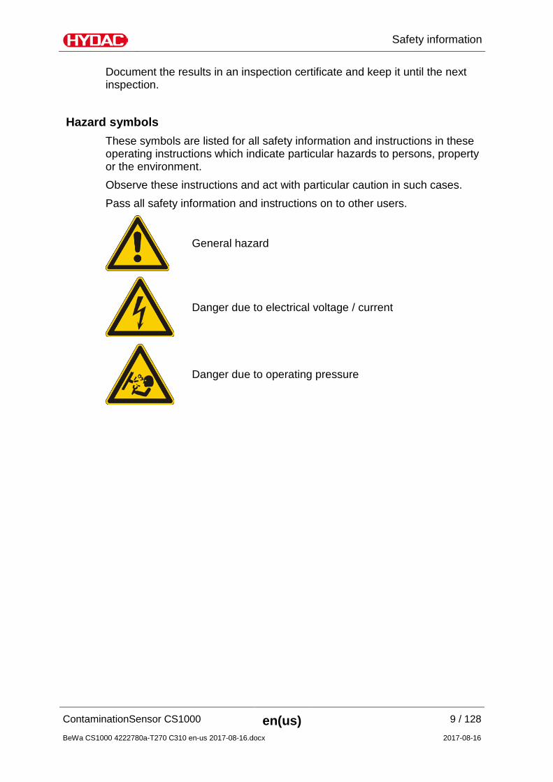
Hazard symbols These symbols are listed for all safety information and instructions in these operating instructions which indicate particular hazards to persons, property or the environment. Observe these instructions and act with particular caution in such cases. Pass all safety information and instructions on to other users.
Signal words and their meaning in the safety information and instructions
In these instructions you will find the following signal words:
DANGER DANGER – The signal word indicates a hazardous situation with a high level of risk, which, if not avoided, will result lethal or serious injury.
WARNING WARNING – The signal word indicates a hazardous situation with a medium level of risk, which, if not avoided, can result lethal or serious injury.
CAUTION CAUTION – The signal word indicates a hazardous situation with a low level of risk, which, if not avoided, can result in minor or moderate injury.
NOTICE NOTICE – The signal word indicates a hazardous situation with a high level of risk, which, if not avoided, will result in damage to property.
Structure of the safety information and instructions All warning instructions in this manual are highlighted with pictograms and signal words. The pictogram and the signal word indicate the severity of the danger. Warning instructions listed before an activity are laid out as follows:
HAZARD SYMBOL
SIGNAL WORD
Type and source of danger
Consequence of the danger
► Measures to avert danger
Observe regulatory information Observe the following regulatory information and directives:
• Legal and local regulations for accident prevention
• Legal and local regulations for environmental protection
Proper/Designated Use Claims for defects or liability, regardless of the legal foundation, do not apply with incorrect or improper installation, commissioning, usage, handling, storage, maintenance, repair, use of unsuitable components or other circumstances for which HYDAC is not responsible. HYDAC is not responsible for the installation, integration, selection of interfaces to / into your system nor for the use or functionality of your system. Only use the sensor for the application described in the following. The ContaminationSensor CS1000 serves to continuously monitor solid particulate contamination in hydraulic and lubrication systems. Proper or designated use of the product extends to the following:
• Observing all instructions contained in the instruction manual.
• performing inspection and maintenance work. Depending on the version (see model code), you may use the CS only in connection with the following media:
NOTICE
Impermissible operating media
The ContaminationSensor will be destroyed.
► Operate the ContaminationSensor only with the permissible operating fluids: - CS 1xx0 is suitable for operation with mineral oils or mineral-oil-based raffinates. - CS 1xx1 is suitable for phosphate esters.
► Note the maximum operating pressure of 350 bar / 5075 psi.
Improper Use or Use Deviating from Intended Use
DANGER
Hazard due to use of the unit other than that intended
Bodily injury and damage to property will result when operated improperly.
► Never operate the sensor in potentially explosive atmospheres.
► The sensor is only to be used with the permitted media.
Any use extending beyond this or deviating therefrom shall not be considered intended use. HYDAC FILTER SYSTEMS GMBH will assume no liability for any damage resulting from such use. The user alone shall assume any and all associated risk. Improper use may result in hazards and/or will damage the sensor. Examples of improper use: Operation in potentially explosive atmospheres. Operation with a non-approved medium. Operation under non-approved operational conditions. Operation when the safety devices are defective. Modifications to the sensor made by the user or purchaser. Inadequate monitoring of parts that are subject to wear and tear. Improperly performed repair work.
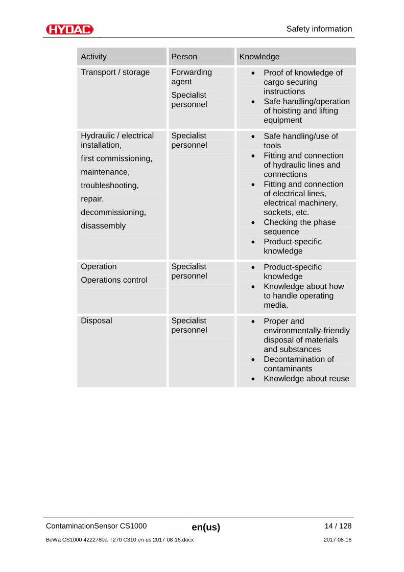
Qualifications of personnel / target group Persons who work on the sensor must be aware of the associated hazards when using it. Auxiliary and specialist personnel must have read and understood the operating instructions, in particular the safety information and instructions, and applicable regulations before beginning work. The operating instructions and applicable regulations are to kept so they are accessible for operating and specialist personnel. These operating instructions are intended for: Auxiliary personnel: such persons have been instructed about the sensor and are aware of potential hazards due to improper use. Specialist personnel: such persons with corresponding specialist training and several years' work experience. They are able to assess and perform the work assigned to them, they are also able to recognize potential hazards.
Storing the sensor Store the sensor in a clean, dry place, in the original packing, if possible. Do not remove the packing until you are ready to install the unit. Rinse the sensor completely with Cleanoil before putting it into storage Use and dispose of used cleaning agents and flushing oils properly and in an environmentally friendly way. The conditions required for storage are in the "TECHNICAL DATA" chapter on page 106.
Decoding the model code label
For identification details of the ContaminationSensor, see the model code label. This is located on the back of the unit and contains the exact product description and the serial number.
Row -> Description
Model -> Model code; for details, see page 111
P/N -> Part no.
S/N -> Serial no.
Date -> Year/week of production and hardware index
Checking the scope of delivery The ContaminationSensor CS1000 comes packed and factory-assembled. Before commissioning the CS, please check no items are missing from the package. The following items are supplied: Qty Designation
1 ContaminationSensor, CS1000 series (Model in acc. with the order - see model code)
2 O-rings (4.8 x 1.78 mm, 80 Shore, FKM) (Only with connection type "Flange connection" = model code: CS1xxx-x-x-x-x-1/-xxx)
1 FMM-P upgrade kit with installation instructions (Only with connection type "Flange connection" = model code: CS1xxx-x-x-x-x-1/-xxx)
1 CD with CS1000 operation and maintenance instructions (this document in various languages)
1 CD with FluMoS software (Fluid Monitoring Software)
CS1000 Characteristics The ContaminationSensor Series CS1000 is a stationary measurement unit for the continuous monitoring of particulate contamination in hydraulic and lubrication systems. The CS is designed to be used in low- or high-pressure hydraulic and lubrication circuits and test benches where a small amount of oil (between 30 ml/min and 500 ml/min) is diverted for measurement purposes. The ContaminationSensor is approved for a maximum operating pressure (see specification on type label) and viscosity of up to 1000 mm²/s. Particulate contamination is detected with an optical measurement cell The sensor is available with the following options:
• with or without 6-digit display and keypad (can be rotated by 270°)
• with 4 - 20 mA or 2 - 10 V analogue output
• Results are output as a cleanliness code according to:ISO 4406:1999 and SAE AS 4059(D) or ISO 4406:1987 and NAS or ISO4406:1999 and SAE AS 4059(D)
• pipe / hose installation or flange installation All models feature an analog electric output and an RS485 interface for outputting the measured cleanliness class. In addition, all CS1000's have a switching output.
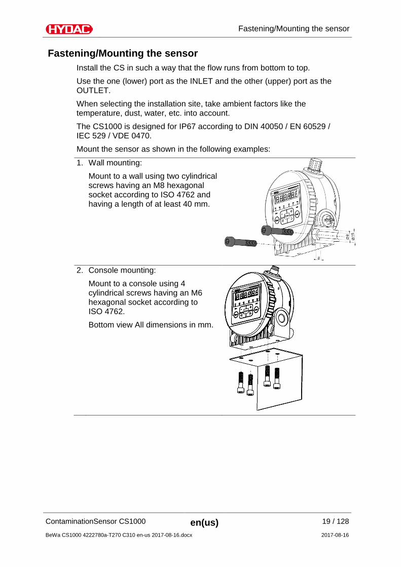
Fastening/Mounting the sensor Install the CS in such a way that the flow runs from bottom to top. Use the one (lower) port as the INLET and the other (upper) port as the OUTLET. When selecting the installation site, take ambient factors like the temperature, dust, water, etc. into account. The CS1000 is designed for IP67 according to DIN 40050 / EN 60529 / IEC 529 / VDE 0470. Mount the sensor as shown in the following examples:
1. Wall mounting: Mount to a wall using two cylindrical screws having an M8 hexagonal socket according to ISO 4762 and having a length of at least 40 mm.
2. Console mounting:
Mount to a console using 4 cylindrical screws having an M6 hexagonal socket according to ISO 4762. Bottom view All dimensions in mm.
3. Installing on a mounting plate: Mount to a mounting plate or control block using 4 cylindrical screws having an M6 hexagonal socket according to ISO 4762.
Continuous rotation of sensor display
The display can be continuously rotated by a total of 270°; 180° counterclockwise and 90° clockwise. Rotate the display by hand in the corresponding direction. No tools are required for rotating the display.
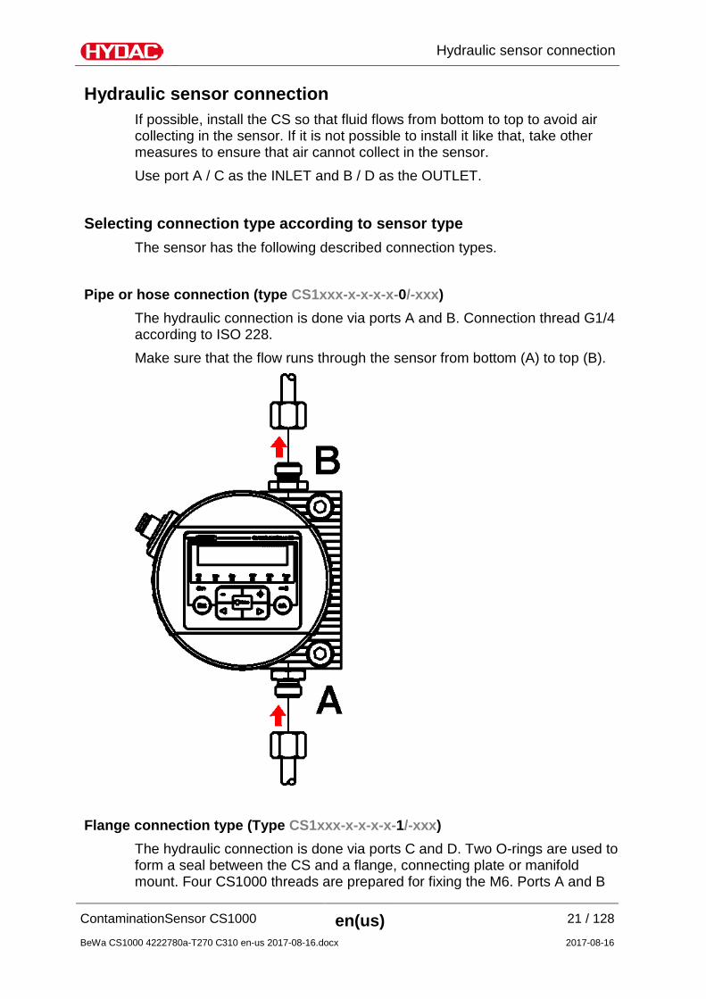
Hydraulic sensor connection If possible, install the CS so that fluid flows from bottom to top to avoid air collecting in the sensor. If it is not possible to install it like that, take other measures to ensure that air cannot collect in the sensor. Use port A / C as the INLET and B / D as the OUTLET.
Selecting connection type according to sensor type The sensor has the following described connection types.
Pipe or hose connection (type CS1xxx-x-x-x-x-0/-xxx) The hydraulic connection is done via ports A and B. Connection thread G1/4 according to ISO 228. Make sure that the flow runs through the sensor from bottom (A) to top (B).
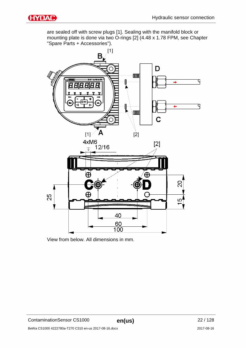
Flange connection type (Type CS1xxx-x-x-x-x-1/-xxx) The hydraulic connection is done via ports C and D. Two O-rings are used to form a seal between the CS and a flange, connecting plate or manifold mount. Four CS1000 threads are prepared for fixing the M6. Ports A and B
are sealed off with screw plugs [1]. Sealing with the manifold block or mounting plate is done via two O-rings [2] (4.48 x 1.78 FPM, see Chapter "Spare Parts + Accessories").
Hydraulic installation of sensor If possible, install the CS so that fluid flows from bottom to top to avoid air collecting in the sensor. If it is not possible to install it like that, take other measures to ensure that air cannot collect in the sensor. Use port A / C as the INLET and B / D as the OUTLET. Depending on your order, the CS features the following hydraulic connection types: Pipe/hose connection: The CS is connected to the hydraulic system via ports A and B using a pipe or hose.
Flange connection: The CS is screwed to a flange, connecting plate, manifold mount or control block, with flow through the unit via ports C and D on the bottom. Ports A and B exist but are sealed with a screw plug.
Determine the operating pressure of the hydraulic system and see whether it is within the permissible flow range for the CS inlet.
NOTICE
Excessive operating pressure
The ContaminationSensor will be destroyed.
► Note the maximum operating pressure of 350 bar / 5075 psi.
Selecting measurement location at the hydraulic systems In order to obtain cleanliness values that are continuous and coherent in real time, select a suitable measuring point according to the following guidelines:
WRONG WRONG OK
1
Select the measurement point so that the sample measured comes from a turbulent location, with a good flow. For example: on a pipe elbow, etc.
2
Install the sensor near the measurement point to achieve as timely results as possible.
3
During installation, avoid creating a "siphon" trap for particle deposits in the line (sedimentation).
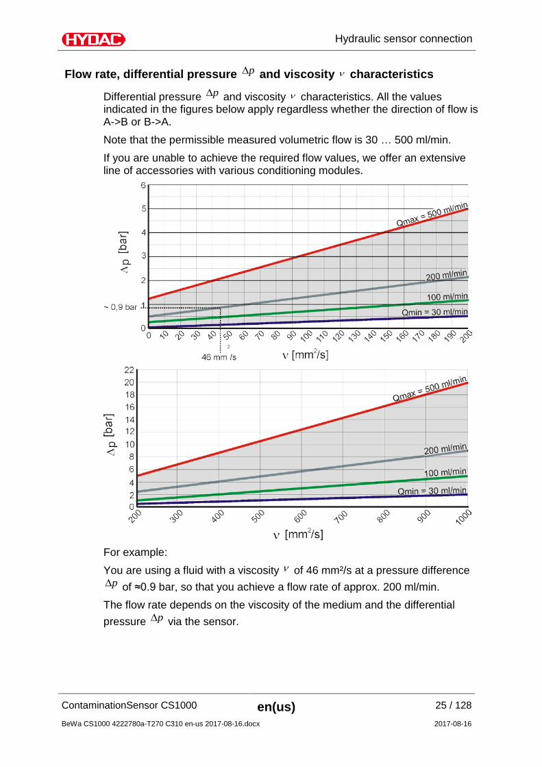
Flow rate, differential pressure p∆ and viscosity ν characteristics
Differential pressure p∆ and viscosity ν characteristics. All the values indicated in the figures below apply regardless whether the direction of flow is A->B or B->A. Note that the permissible measured volumetric flow is 30 … 500 ml/min. If you are unable to achieve the required flow values, we offer an extensive line of accessories with various conditioning modules.
For example: You are using a fluid with a viscosity ν of 46 mm²/s at a pressure difference
p∆ of ≈0.9 bar, so that you achieve a flow rate of approx. 200 ml/min. The flow rate depends on the viscosity of the medium and the differential pressure p∆ via the sensor.
► Note the maximum operating pressure of 350 bar / 5075 psi.
Observe the following sequence when connecting the sensor to the hydraulic system:
1. Connect the return line to the OUTLET of the CS. G1/4 ISO 228 threaded connection, recommended diameter of line ≥ 4 mm.
2. Then connect the other end of the return line to the system tank, for example.
3. Check the pressure at the measurement location. Note the maximum operating pressure.
4. Connect the measurement line to the INLET port of the CS. Connector threads G1/4 ISO 228. We recommend an internal Ø ≤ 4mm for the line in order to prevent particle deposits (sedimentation).
If particles ≥ 400 µm are anticipated in the hydraulic systems, install a strainer upstream from the ContaminationSensor. (e.g. CM-S).
5. Connect the other end of the measurement line to the measurement point on the hydraulic system.
Oil begins to flow as soon as the ContaminationSensor is connected with the pressure line.
8 Switching output (passive, n.c.) The analogue output is an active source of 4-20 mA or 2-10 V DC. The switching output is a passive n-switching Power MOSFET and is normally open. There is contact between the plug housing and the housing.
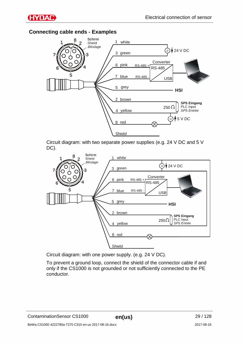
Connection cable - Assignment / Color coding Our accessories list on page 105 includes the required connection cables of various lengths with one connection plug (M12x1, 8-pin, according to DIN VDE 0627) and an open end. HYDAC accessory cable color coding is listed in the table below.
Circuit diagram: with two separate power supplies (e.g. 24 V DC and 5 V DC).
1
2
3
4
5
6
7
8
Shield
24 V DC
white
green
pink RS-485 +
RS-485 -blue
grey
brown
yellow
red
USB
RS-485Converter
HSI
=
250
1
7
65
4
3
28
SPS EingangPLC InputSPS Entrée
SchirmShieldBlindage
Circuit diagram: with one power supply. (e.g. 24 V DC). To prevent a ground loop, connect the shield of the connector cable if and only if the CS1000 is not grounded or not sufficiently connected to the PE conductor.
Setting the measuring mode Once the sensor is switched on or supplied with power, it automatically runs in the measuring mode that has been set.
Mode "M1": Continuous measurement Application: Stand-alone sensor Data output: Display & RS485 & analog output Purpose: Measurement only Function: Continuous measurement of cleanliness class Switching
function only for "Device ready".
Mode "M2": Continuous measurement and switching Application: Stand-alone sensor with alarm standby display Data output: Display & RS485 & analog output & switching output Purpose: Continuous measurement and controlling of signal lamps
etc. Function: Continuous measurement of solid contamination,
continuous monitoring of programmable limit values; switching output is activated to switch on the monitor display or an alarm on site
Mode "M3": Filter to cleanliness class and stop Application: Controlling a filter unit Data output: Display & RS485 & analog output & switching output Purpose: For cleaning up a hydraulic reservoir Function: Control of a filter unit, continuous measurement of solid
contamination. If pre-programmed cleanliness level is achieved 5 times in sequence, the pump is stopped. Load the switching output with a maximum of 2 A and 30 V DC.
Mode "M4": Filter to continuously monitor cleanliness class Application: Control of stationary offline filtration unit Data output: Display & RS485 & analog output & switching output Purpose: Establish continuous monitoring of cleanliness class
between min./max. limit values. Function: Control of a filter unit, continuous measurement of solid
contamination. If min./max. limit values are pre-programmed, the CS switches the filtration unit on/off to maintain the cleanliness within the limit value range.
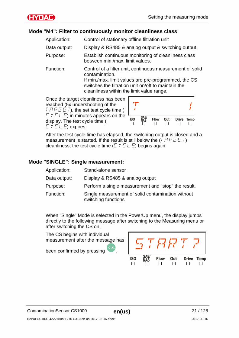
Once the target cleanliness has been reached (5x undershooting of the
), the set test cycle time () in minutes appears on the
display. The test cycle time () expires.
After the test cycle time has elapsed, the switching output is closed and a measurement is started. If the result is still below the ( ) cleanliness, the test cycle time ( ) begins again.
Mode "SINGLE": Single measurement: Application: Stand-alone sensor Data output: Display & RS485 & analog output Purpose: Perform a single measurement and "stop" the result. Function: Single measurement of solid contamination without
switching functions When "Single" Mode is selected in the PowerUp menu, the display jumps directly to the following message after switching to the Measuring menu or after switching the CS on: The CS begins with individual measurement after the message has
Operating the CS1x2x sensor using the keypad If the sensor is switched on or supplied with power, the display shows HYDAC CS1000 in moving letters, then the firmware version is displayed for 2 seconds.
This is followed by a countdown: WAIT99 … WAIT0. The duration of the countdown corresponds to the set measurement time MTIME. This means that the countdown runs from 99 ... 0 within the set measurement time (factory setting = 60 sec).
Item LED Description For details, see page
A STATUS Status display 92
B Display 6-figure display with 17 segments each 92
C Measured variable
Display of respective measured variable, e.g: ISO / SAE / NAS
34
D Service variable Display of respective service variable, e.g.: Flow / Out / Drive / Temp
35
E Switch point 1 SP 1
Indicates the status of the switching output. When the LED is lit, the switching output is activated, i.e. the switch is closed.
Function of the Keys The following keys are available to you for operating and setting the CS1x2x: Key Function
o.k.
You jump one menu level down. You confirm a changed value at the lowest menu level. You confirm at the top menu level to save or reject a change in value.
Esc
You jump up one menu level. In order to leave the menu without changing the values, press the ESC key until SAVE appears in the display.
With the keys switch to CANCEL and confirm
with the o.k.
key or wait 30 seconds without pressing a key. You exit the menu without changing the values.
+
You change values / settings on the lowest menu level.
They scroll through display ISO / SAE/NAS / Flow / Out / Drive / Temp. You move through the menu. You select numbers.
Once the lowest menu level has been reached, the values in the display will start to flash.
Measured variables on the display The measured variables give you information on the oil cleanliness in the system. You will receive a measured value with an accuracy of ± 1/2 ISO code within the calibrated range.
Service variables on the display The service variables inform you about the current status in the ContaminationSensor. The service variables are not calibrated. They represent an approximate value for installing the sensor in the hydraulic system.
Flow (flow rate) Display Description
Flow rate in permissible range
Out (Analogue output)
Display Description
Current or voltage output at the analog output.
(example: 13.8 mA)
Drive (performance of the LED)
Display Description
Performance (1-100%) of the LED in the sensor.(example: 60%)
Temp (Temperature)
Display Description
Fluid temperature in the sensor. (example: 29.5 °C or 84.2 °F)
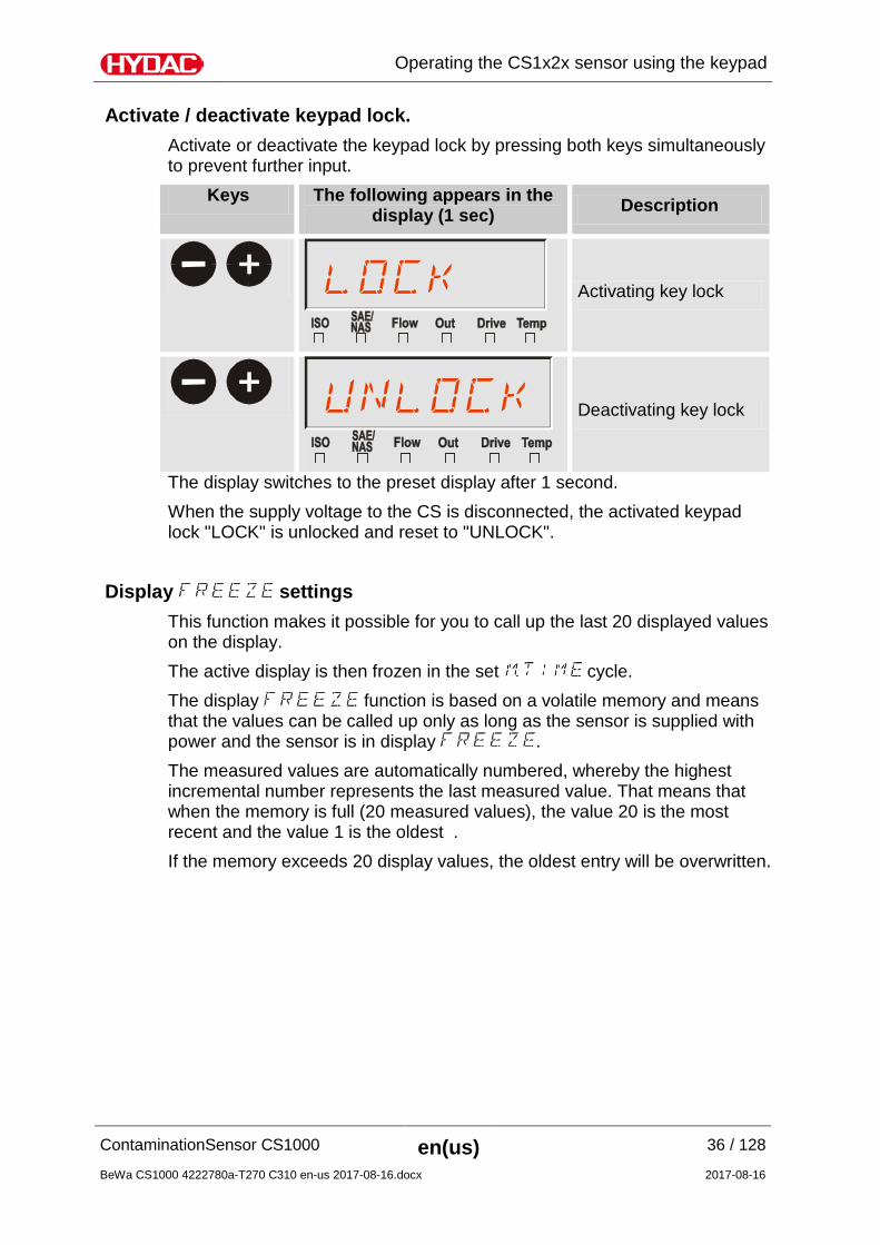
Activate / deactivate keypad lock. Activate or deactivate the keypad lock by pressing both keys simultaneously to prevent further input.
Keys The following appears in the display (1 sec) Description
+
Activating key lock
+
Deactivating key lock
The display switches to the preset display after 1 second. When the supply voltage to the CS is disconnected, the activated keypad lock "LOCK" is unlocked and reset to "UNLOCK".
Display settings This function makes it possible for you to call up the last 20 displayed values on the display. The active display is then frozen in the set cycle. The display function is based on a volatile memory and means that the values can be called up only as long as the sensor is supplied with power and the sensor is in display . The measured values are automatically numbered, whereby the highest incremental number represents the last measured value. That means that when the memory is full (20 measured values), the value 20 is the most recent and the value 1 is the oldest . If the memory exceeds 20 display values, the oldest entry will be overwritten.
Activating display To activate or deactivate the history memory , press both keys simultaneously. The function starts with the display of the most recent measured value.
Keys The following appears in the display (1 sec) <-> The following appears in
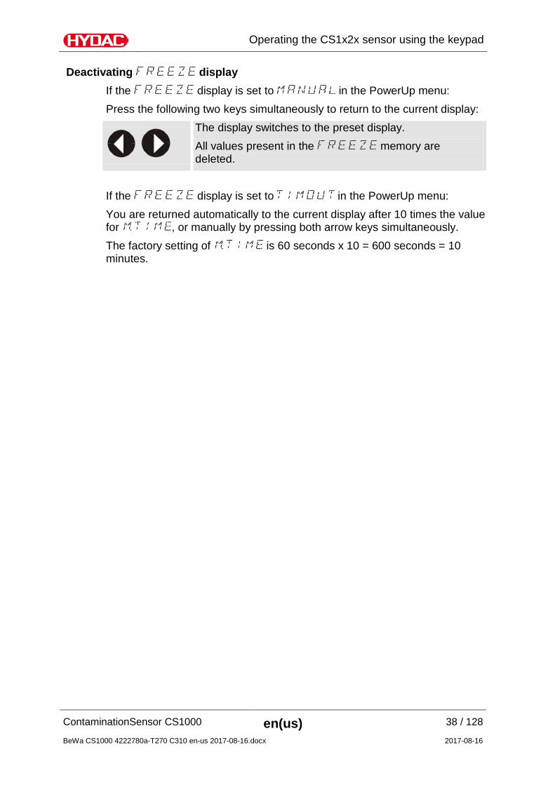
Deactivating display If the display is set to in the PowerUp menu: Press the following two keys simultaneously to return to the current display:
The display switches to the preset display. All values present in the memory are deleted.
If the display is set to in the PowerUp menu: You are returned automatically to the current display after 10 times the value for , or manually by pressing both arrow keys simultaneously. The factory setting of is 60 seconds x 10 = 600 seconds = 10 minutes.
- Handling flow rate error The service variable Flow is calculated in the sensor using the particle signal. For different reasons (e.g. fluid supply of the sensor not provided, fluid too clean, too much air in the fluid, etc.) the flow detection may be affected to such an extent that it is no longer possible to determine any flow. These cases are handled as flow errors. The behavior of the sensor when flow errors arise can be set in the PowerUp menu. The following both settings are possible:
- All flow errors will be issued to all data interfaces. See chapter “Status Messages“ on page 92.
- No flow errors will be issued to the data interfaces. The error message / error status is suppressed and last measured value will be issued. Exception: If the sensor cannot at first detect any flow in its first measurement cycle after a PowerUp, it is in an undefined status and issues this according to chapter "Status Messages" on page 92. The measured values will be updated as soon as the sensor is operated in the specified range again.
Please note with this setting that it cannot be seen if the shown measured value is an old one or a current value. This means, for example, that if the pump is faulty or the system pressure collapses, no other status message or warning will be made or issued.
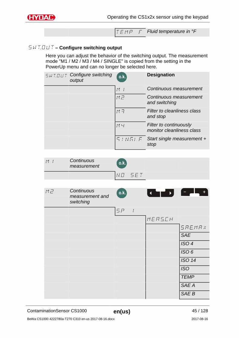
Here you can adjust the behavior of the switching output. The measurement mode "M1 / M2 / M3 / M4 / SINGLE" is copied from the setting in the PowerUp menu and can no longer be selected here.
Here you can adjust the behavior of the switching output. The measurement mode "M1 / M2 / M3 / M4 / SINGLE" is copied from the setting in the PowerUp menu and can no longer be selected here.
Using switching output You can use the switching output in the modes described below. For a further description of the measurement modes, see page 30.
Mode "M1": Continuous measurement Purpose: Measurement only Function: Continuous measurement of cleanliness class Switching
function only for "Device ready".
Mode "M2": Continuous measurement and switching Purpose: Continuous measurement and controlling of signal lamps etc. Function: Continuous measurement of solid contamination, continuous
monitoring of programmed limit values; the switching output is enabled and switches on the monitoring display or alarm on site
Mode "M3": Filter to cleanliness class and stop Purpose: Clean up hydraulic reservoir Function: Control of a filter unit, continuous measurement of solid
contamination. If pre-programmed cleanliness level is reached 5 times in sequence, the pump is stopped.
Mode "M4": Filter to continuously monitor cleanliness class Purpose:
Establish continuous monitoring of cleanliness class between min/max limit values
Function: If min/max limit values are pre-programmed, the CS switches the filter unit on/off to keep cleanliness within the limit value range. Load the switching output with a maximum of 2 A and 30 V DC.
Mode " ": Single measurement Purpose: Perform a single measurement and "stop" the result. Function: Single measurement of solid contamination without switching
functions Switching function only for "Device ready".
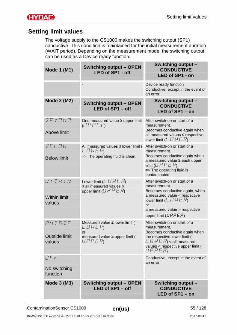
Setting limit values The voltage supply to the CS1000 makes the switching output (SP1) conductive. This condition is maintained for the initial measurement duration (WAIT period). Depending on the measurement mode, the switching output can be used as a Device ready function.
Mode 1 (M1) Switching output – OPEN LED of SP1 - off
Switching output – CONDUCTIVE
LED of SP1 - on
- Device ready function Conductive, except in the event of an error
Mode 2 (M2) Switching output – OPEN LED of SP1 – off
Switching output – CONDUCTIVE
LED of SP1 – on
One measured value ≥ upper limit ( )
After switch-on or start of a measurement. Becomes conductive again when all measured values ≤ respective lower limit ( )
Above limit
All measured values ≤ lower limit ()
=> The operating fluid is clean.
After switch-on or start of a measurement. Becomes conductive again when a measured value ≥ each upper limit ( ) => The operating fluid is contaminated.
After switch-on or start of a measurement. Becomes conductive again, when a measured value < respective lower limit ( ) or a measured value > respective upper limit (UPPER)
Within limit values
Measured value ≤ lower limit ()
or measured value ≥ upper limit (
)
After switch-on or start of a measurement. Becomes conductive again when the respective lower limit (
) < all measured values < respective upper limit (
)
Outside limit values
- Conductive, except in the event of an error
No switching function
Mode 3 (M3) Switching output – OPEN LED of SP1 – off
Reading the analog output Depending on CS model, the analogue output is available as a 4 – 20 mA or 2 – 10 V signal. You can recognize the type of analog output from the model code of the sensor. CS Model Code Analog output
CS 1 x x x - A – x – x – x – x /-xxx 4 … 20 mA
CS 1 x x x - B – x – x – x – x /-xxx 2 … 10 V Observe the design of the analog output in the order. It is not possible to internally change the analog output over later. In the measuring menu, select one of the following signals for the analog output:
• SAE classes acc. to AS 4059
• ISO Code acc. to ISO 4406:1999
• ISO Code acc. to ISO 4406:1987
• NAS Class 1638
• Fluid temperature
SAE - classes acc. to AS 4059 The following SAE values can be read out via the analogue output: • SAE A-D (SAEMAX) Only one single value is output. • SAE A / B / C / D All values are sequentially time-coded before output. • SAE A / SAE B / SAE C / SAE D Only one value is output. • SAE+T All values are sequentially time-coded before output. • HDA.SAE All values are sequentially time-coded before output.
This signal is planned for the HDA 5500, but it can be used also in other applications.
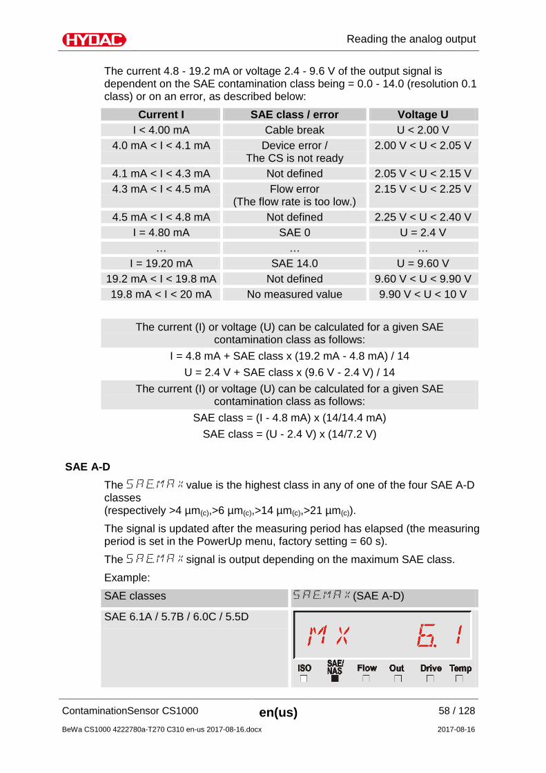
The current 4.8 - 19.2 mA or voltage 2.4 - 9.6 V of the output signal is dependent on the SAE contamination class being = 0.0 - 14.0 (resolution 0.1 class) or on an error, as described below:
Current I SAE class / error Voltage U I < 4.00 mA Cable break U < 2.00 V
4.0 mA < I < 4.1 mA Device error / The CS is not ready
2.00 V < U < 2.05 V
4.1 mA < I < 4.3 mA Not defined 2.05 V < U < 2.15 V 4.3 mA < I < 4.5 mA Flow error
(The flow rate is too low.) 2.15 V < U < 2.25 V
4.5 mA < I < 4.8 mA Not defined 2.25 V < U < 2.40 V I = 4.80 mA SAE 0 U = 2.4 V
… … … I = 19.20 mA SAE 14.0 U = 9.60 V
19.2 mA < I < 19.8 mA Not defined 9.60 V < U < 9.90 V 19.8 mA < I < 20 mA No measured value 9.90 V < U < 10 V
The current (I) or voltage (U) can be calculated for a given SAE contamination class as follows:
I = 4.8 mA + SAE class x (19.2 mA - 4.8 mA) / 14 U = 2.4 V + SAE class x (9.6 V - 2.4 V) / 14
The current (I) or voltage (U) can be calculated for a given SAE contamination class as follows:
SAE class = (I - 4.8 mA) x (14/14.4 mA) SAE class = (U - 2.4 V) x (14/7.2 V)
SAE A-D
The value is the highest class in any of one of the four SAE A-D classes (respectively >4 µm(c),>6 µm(c),>14 µm(c),>21 µm(c)). The signal is updated after the measuring period has elapsed (the measuring period is set in the PowerUp menu, factory setting = 60 s). The signal is output depending on the maximum SAE class. Example: SAE classes (SAE A-D)
For basic information about cleanliness classes, see page 112 ff. The SAE classification consists of whole numbers. Better trend recognition is based on a resolution of 0.1 contamination classes as supplied by the CS 1000. To convert a decimal value to an integer, the decimal value has to be rounded up. For example: a readout of SAE 10.7 is, according to SAE 4059 (D), a class SAE 11.
SAE A / SAE B / SAE C / SAE D The SAE X signal consists of a measured value (SAE A / SAE B / SAE C / or SAE D) which is permanently transmitted as described in the following.
= Duration of the measurement as set in the PowerUp menu, see page 40.
HDA.SAE – Analog signal SAE for HDA 5500 The HDA.SAE signal consists of 6 values (START / SAE A / SAE B / SAE C / SAE D / Status) which are output sequentially. Synchronization with the downstream control unit is a prerequisite. The signal output is as follows:
ISO code according to ISO 4406:1999 The following ISO values can be read out via the analogue output: • ISO 4 / ISO 6 / ISO 14 Only one value is output. • ISO code in 3 figures ( >4µm(c) / >6µm(c) / >14µm(c) ) All values are sequentially time-coded before output. • ISO+T All values are sequentially time-coded before output. • HDA.ISO All values are sequentially time-coded before output.
This signal is planned for the HDA 5500, but it can be used also in other applications.
The current 4.8 - 19.2 mA or voltage 2.4 - 9.6 V of the output signal, dependent on the ISO contamination class 0.0 - 24.28 (resolution 1 class) or on an error, is as described below:
Current I ISO code / error Voltage U I < 4.0 mA Cable break U< 2.0 V
4.0 mA < I < 4.1 mA Device error / The CS is not ready
2.0 V < U < 2.05 V
4.1 mA < I < 4.3 mA Not defined 2.05 V < U < 2.15 V 4.3 mA < I < 4.5 mA Flow error
(The flow rate is too low.) 2.15 V < U < 2.25 V
4.5 mA < I < 4.8 mA Not defined 2.25 V < U < 2.4 V I = 4.80 mA ISO 0 U = 2.40 V
… … … I = 19.20 mA ISO 24.28 U = 9.60 V
19.2 mA < I < 19.8 mA
Not defined 9.60 V < U < 9.90 V
19.8 mA < I < 20 mA No measured value 9.90 V < U < 10 V
The current (I) or voltage (U) can be calculated for a given ISO contamination class as follows:
I = 4.8 mA + ISO code x (19.2 mA - 4.8 mA) / 24.28 U = 2.4 V + ISO Code x (9.6 V - 2.4 V) / 24.28
The current (I) or voltage (U) can be calculated for a given ISO contamination class as follows:
ISO Code = (I - 4.8 mA) x (24.28 / 14.4 mA) ISO Code = (U - 2.4 V) x (24.28 / 7.2 V)
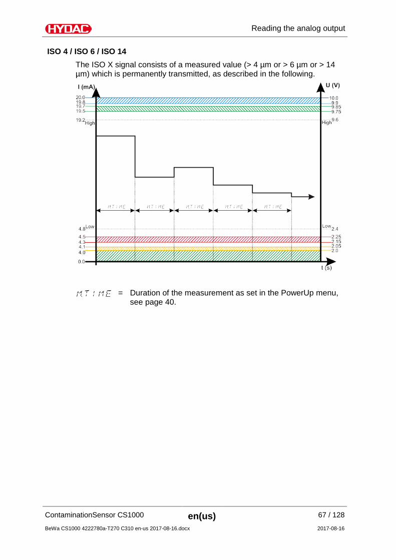
ISO 4 / ISO 6 / ISO 14 The ISO X signal consists of a measured value (> 4 µm or > 6 µm or > 14 µm) which is permanently transmitted, as described in the following.
= Duration of the measurement as set in the PowerUp menu, see page 40.
HDA.ISO – Analog signal ISO for HDA 5500 The HDA.ISO signal consists of 6 measured values (START / ISO 4 / ISO 6 / ISO 14 / ISO 21 / Status) which are output sequentially. Synchronization with the downstream control unit is a prerequisite. The signal output is as follows:
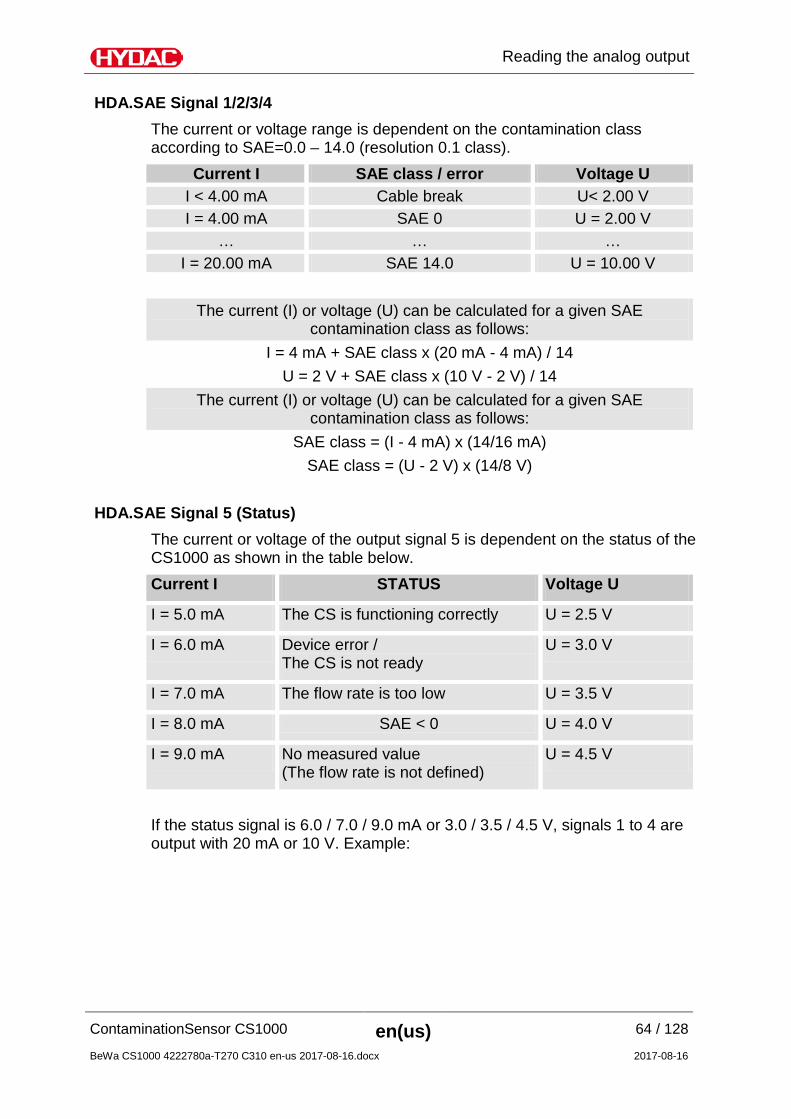
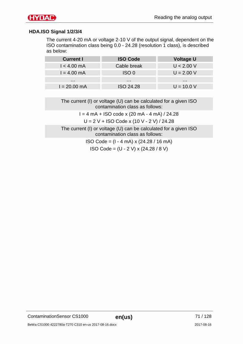
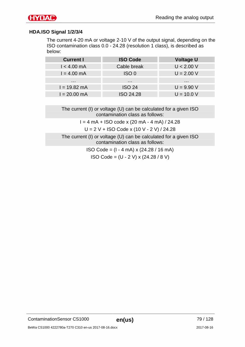
HDA.ISO Signal 1/2/3/4 The current 4-20 mA or voltage 2-10 V of the output signal, dependent on the ISO contamination class being 0.0 - 24.28 (resolution 1 class), is described as below:
Current I ISO Code Voltage U I < 4.00 mA Cable break U < 2.00 V I = 4.00 mA ISO 0 U = 2.00 V
… … … I = 20.00 mA ISO 24.28 U = 10.0 V
The current (I) or voltage (U) can be calculated for a given ISO contamination class as follows:
I = 4 mA + ISO code x (20 mA - 4 mA) / 24.28 U = 2 V + ISO Code x (10 V - 2 V) / 24.28
The current (I) or voltage (U) can be calculated for a given ISO contamination class as follows:
ISO Code = (I - 4 mA) x (24.28 / 16 mA) ISO Code = (U - 2 V) x (24.28 / 8 V)
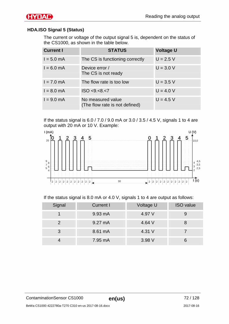
HDA.ISO Signal 5 (Status) The current or voltage of the output signal 5 is, dependent on the status of the CS1000, as shown in the table below. Current I STATUS Voltage U
I = 5.0 mA The CS is functioning correctly U = 2.5 V
I = 6.0 mA Device error / The CS is not ready
U = 3.0 V
I = 7.0 mA The flow rate is too low U = 3.5 V
I = 8.0 mA ISO <9.<8.<7 U = 4.0 V
I = 9.0 mA No measured value (The flow rate is not defined)
U = 4.5 V
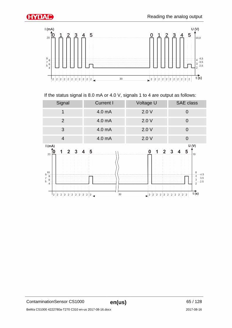
If the status signal is 6.0 / 7.0 / 9.0 mA or 3.0 / 3.5 / 4.5 V, signals 1 to 4 are output with 20 mA or 10 V. Example: I (mA) U (V)
t (s)
4 26 3
9 4,5
10,0
75
3,52,5
8 4
20
2 2 2 2 2 2 2 2 2 2 2 2 2 2 2 2 2 2 2 2 2 230
1 102 23 34 45 50
If the status signal is 8.0 mA or 4.0 V, signals 1 to 4 are output as follows:
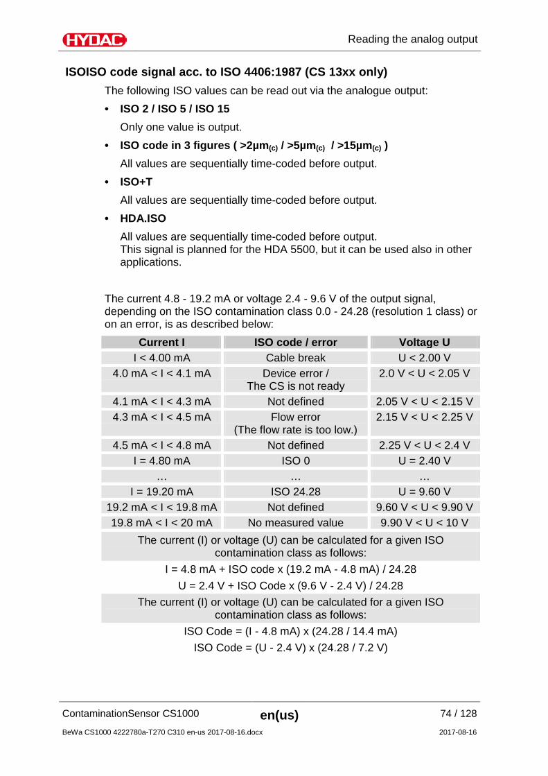
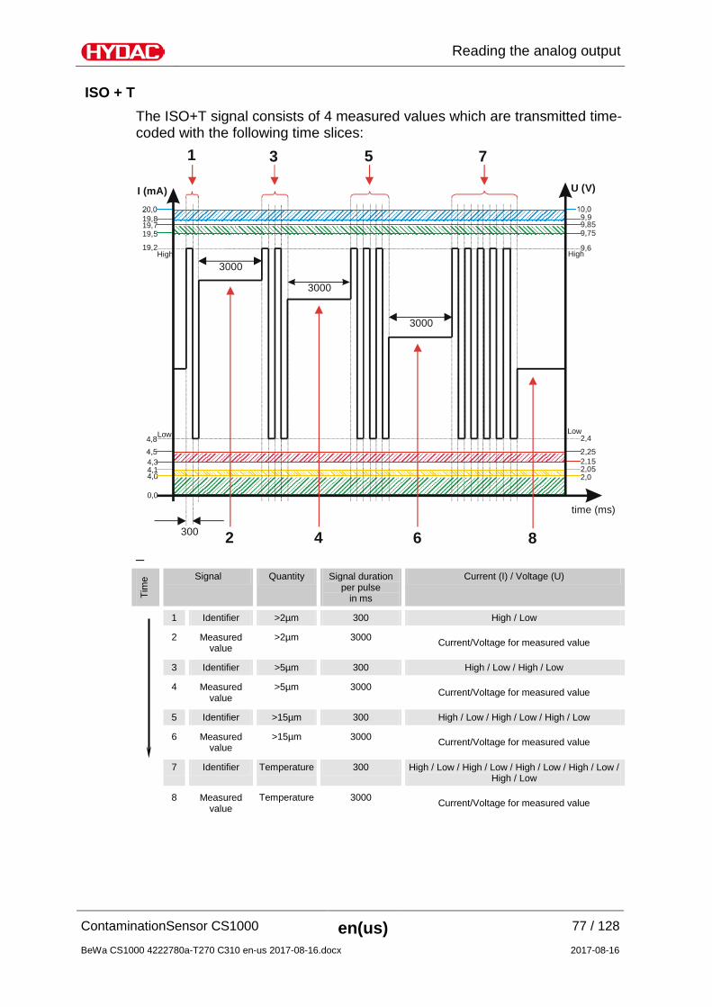
ISOISO code signal acc. to ISO 4406:1987 (CS 13xx only) The following ISO values can be read out via the analogue output: • ISO 2 / ISO 5 / ISO 15 Only one value is output. • ISO code in 3 figures ( >2µm(c) / >5µm(c) / >15µm(c) ) All values are sequentially time-coded before output. • ISO+T All values are sequentially time-coded before output. • HDA.ISO All values are sequentially time-coded before output.
This signal is planned for the HDA 5500, but it can be used also in other applications.
The current 4.8 - 19.2 mA or voltage 2.4 - 9.6 V of the output signal, depending on the ISO contamination class 0.0 - 24.28 (resolution 1 class) or on an error, is as described below:
Current I ISO code / error Voltage U I < 4.00 mA Cable break U < 2.00 V
4.0 mA < I < 4.1 mA Device error / The CS is not ready
2.0 V < U < 2.05 V
4.1 mA < I < 4.3 mA Not defined 2.05 V < U < 2.15 V 4.3 mA < I < 4.5 mA Flow error
(The flow rate is too low.) 2.15 V < U < 2.25 V
4.5 mA < I < 4.8 mA Not defined 2.25 V < U < 2.4 V I = 4.80 mA ISO 0 U = 2.40 V
… … … I = 19.20 mA ISO 24.28 U = 9.60 V
19.2 mA < I < 19.8 mA Not defined 9.60 V < U < 9.90 V 19.8 mA < I < 20 mA No measured value 9.90 V < U < 10 V
The current (I) or voltage (U) can be calculated for a given ISO contamination class as follows:
I = 4.8 mA + ISO code x (19.2 mA - 4.8 mA) / 24.28 U = 2.4 V + ISO Code x (9.6 V - 2.4 V) / 24.28
The current (I) or voltage (U) can be calculated for a given ISO contamination class as follows:
ISO Code = (I - 4.8 mA) x (24.28 / 14.4 mA) ISO Code = (U - 2.4 V) x (24.28 / 7.2 V)
ISO 2 / ISO 5 / ISO 15 The ISO X signal consists of a measured value (> 2 µm or > 5 µm or > 15 µm) which is permanently transmitted, as described in the following.
= Duration of the measurement as set in the PowerUp menu, see page 40.
HDA.ISO – Analog signal ISO for HDA 5500 The HDA.ISO signal consists of 4 measured values (ISO 4 / ISO 6 / ISO 14 / ISO 21 / Status) which are output sequentially. Synchronization with the downstream control unit is a prerequisite. The signal output is as follows:
HDA.ISO Signal 1/2/3/4 The current 4-20 mA or voltage 2-10 V of the output signal, depending on the ISO contamination class 0.0 - 24.28 (resolution 1 class), is described as below:
Current I ISO Code Voltage U I < 4.00 mA Cable break U < 2.00 V I = 4.00 mA ISO 0 U = 2.00 V
… … … I = 19.82 mA ISO 24 U = 9.90 V I = 20.00 mA ISO 24.28 U = 10.0 V
The current (I) or voltage (U) can be calculated for a given ISO contamination class as follows:
I = 4 mA + ISO code x (20 mA - 4 mA) / 24.28 U = 2 V + ISO Code x (10 V - 2 V) / 24.28
The current (I) or voltage (U) can be calculated for a given ISO contamination class as follows:
ISO Code = (I - 4 mA) x (24.28 / 16 mA) ISO Code = (U - 2 V) x (24.28 / 8 V)
HDA.ISO Signal 5 (Status) The current or voltage of the output signal 5 is, depending on the status of the CS1000, described as shown in the table below.
Current I STATUS Voltage U I = 5.0 mA The CS is functioning correctly U = 2.5 V I = 6.0 mA Device error /
The CS is not ready U = 3.0 V
I = 7.0 mA The flow rate is too low U = 3.5 V I = 8.0 mA ISO <9.<8.<7 U = 4.0 V I = 9.0 mA No measured value
(The flow rate is not defined) U = 4.5 V
If the status signal is = 6.0 mA or = 3.0 V, signals 1 to 4 are output with 20 mA or 10 V. Example: I (mA) U (V)
t (s)
4 26 3
9 4,5
10,0
75
3,52,5
8 4
20
2 2 2 2 2 2 2 2 2 2 2 2 2 2 2 2 2 2 2 2 2 230
1 102 23 34 45 50
If the status signal is 8.0 mA or 4.0 V, signals 1 to 4 are output as follows:
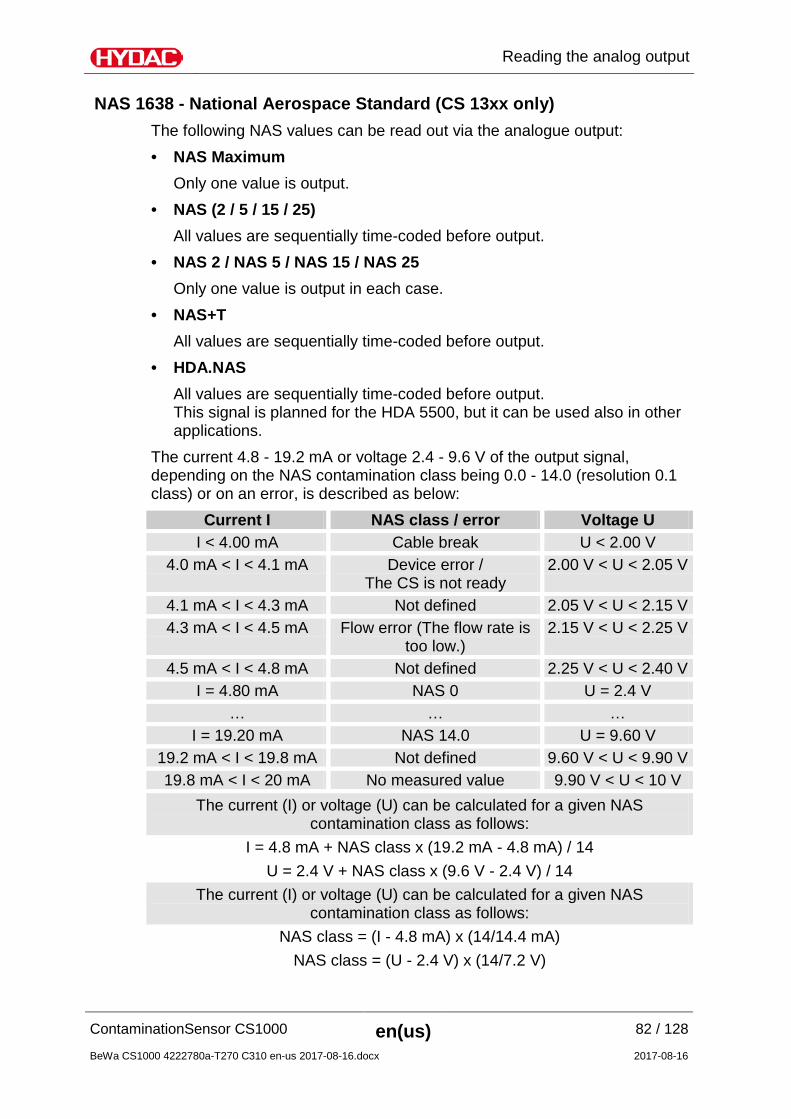
NAS 1638 - National Aerospace Standard (CS 13xx only) The following NAS values can be read out via the analogue output: • NAS Maximum Only one value is output. • NAS (2 / 5 / 15 / 25) All values are sequentially time-coded before output. • NAS 2 / NAS 5 / NAS 15 / NAS 25 Only one value is output in each case. • NAS+T All values are sequentially time-coded before output. • HDA.NAS All values are sequentially time-coded before output.
This signal is planned for the HDA 5500, but it can be used also in other applications.
The current 4.8 - 19.2 mA or voltage 2.4 - 9.6 V of the output signal, depending on the NAS contamination class being 0.0 - 14.0 (resolution 0.1 class) or on an error, is described as below:
Current I NAS class / error Voltage U I < 4.00 mA Cable break U < 2.00 V
4.0 mA < I < 4.1 mA Device error / The CS is not ready
2.00 V < U < 2.05 V
4.1 mA < I < 4.3 mA Not defined 2.05 V < U < 2.15 V 4.3 mA < I < 4.5 mA Flow error (The flow rate is
too low.) 2.15 V < U < 2.25 V
4.5 mA < I < 4.8 mA Not defined 2.25 V < U < 2.40 V I = 4.80 mA NAS 0 U = 2.4 V
… … … I = 19.20 mA NAS 14.0 U = 9.60 V
19.2 mA < I < 19.8 mA Not defined 9.60 V < U < 9.90 V 19.8 mA < I < 20 mA No measured value 9.90 V < U < 10 V
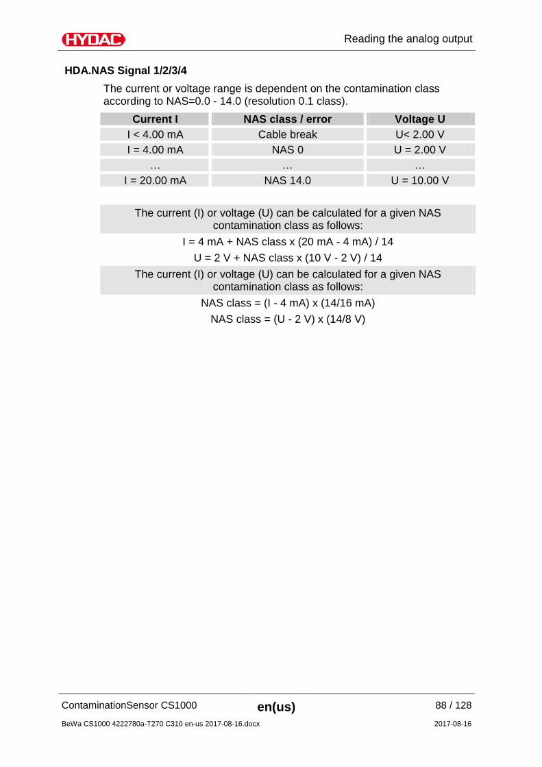
The current (I) or voltage (U) can be calculated for a given NAS contamination class as follows:
I = 4.8 mA + NAS class x (19.2 mA - 4.8 mA) / 14 U = 2.4 V + NAS class x (9.6 V - 2.4 V) / 14
The current (I) or voltage (U) can be calculated for a given NAS contamination class as follows:
NAS class = (I - 4.8 mA) x (14/14.4 mA) NAS class = (U - 2.4 V) x (14/7.2 V)
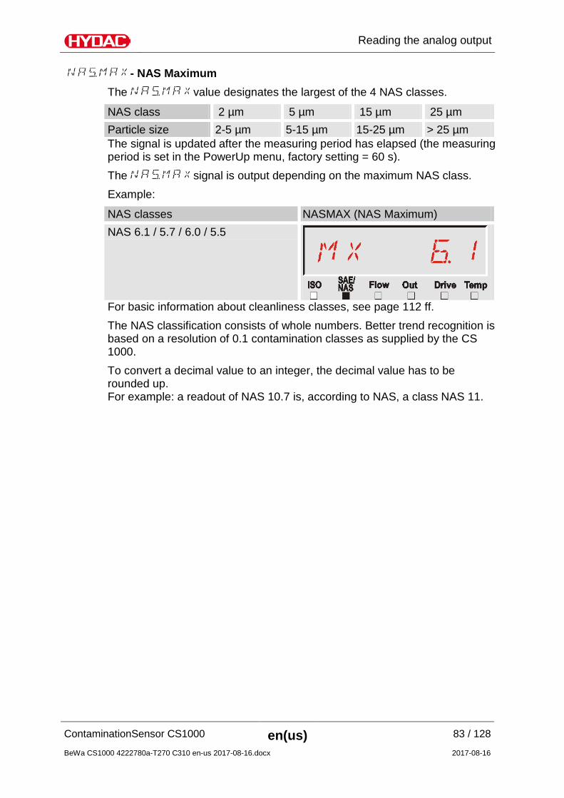
- NAS Maximum The value designates the largest of the 4 NAS classes.
NAS class 2 µm 5 µm 15 µm 25 µm Particle size 2-5 µm 5-15 µm 15-25 µm > 25 µm The signal is updated after the measuring period has elapsed (the measuring period is set in the PowerUp menu, factory setting = 60 s). The signal is output depending on the maximum NAS class. Example:
NAS classes NASMAX (NAS Maximum) NAS 6.1 / 5.7 / 6.0 / 5.5
For basic information about cleanliness classes, see page 112 ff. The NAS classification consists of whole numbers. Better trend recognition is based on a resolution of 0.1 contamination classes as supplied by the CS 1000. To convert a decimal value to an integer, the decimal value has to be rounded up. For example: a readout of NAS 10.7 is, according to NAS, a class NAS 11.
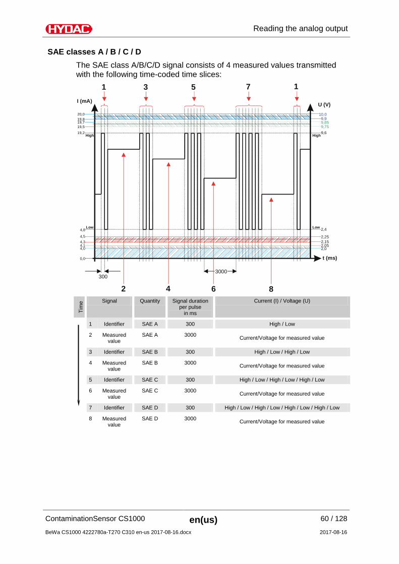
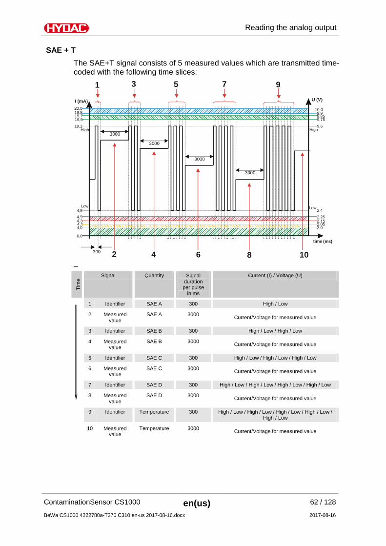
NAS classes (2 / 5 / 15 / 25) The NAS classes 2 / 5 / 15 / 25 signal consists of 4 measured values transmitted with the following time-coded time slices:
4,0
I (mA) U (V)
t (ms)
4,8Low
20,0
19,2High High
Low
4,54,34,1
19,719,5
3003000
1 3 5 7 1
2 4 6 8
2,02,05
2,25
2,4
9,859,75
2,15
9,6
0,0
19,810,09,9
Tim
e Signal Quantity Signal duration per pulse
in ms
Current (I) / Voltage (U)
1 Identifier 2 µm 300 High / Low
2 Measured value
2 µm 3000 Current/Voltage for measured value
3 Identifier 5 µm 300 High / Low / High / Low
4 Measured value
5 µm 3000 Current/Voltage for measured value
5 Identifier 15 µm 300 High / Low / High / Low / High / Low
6 Measured value
15 µm 3000 Current/Voltage for measured value
7 Identifier 25 µm 300 High / Low / High / Low / High / Low / High / Low
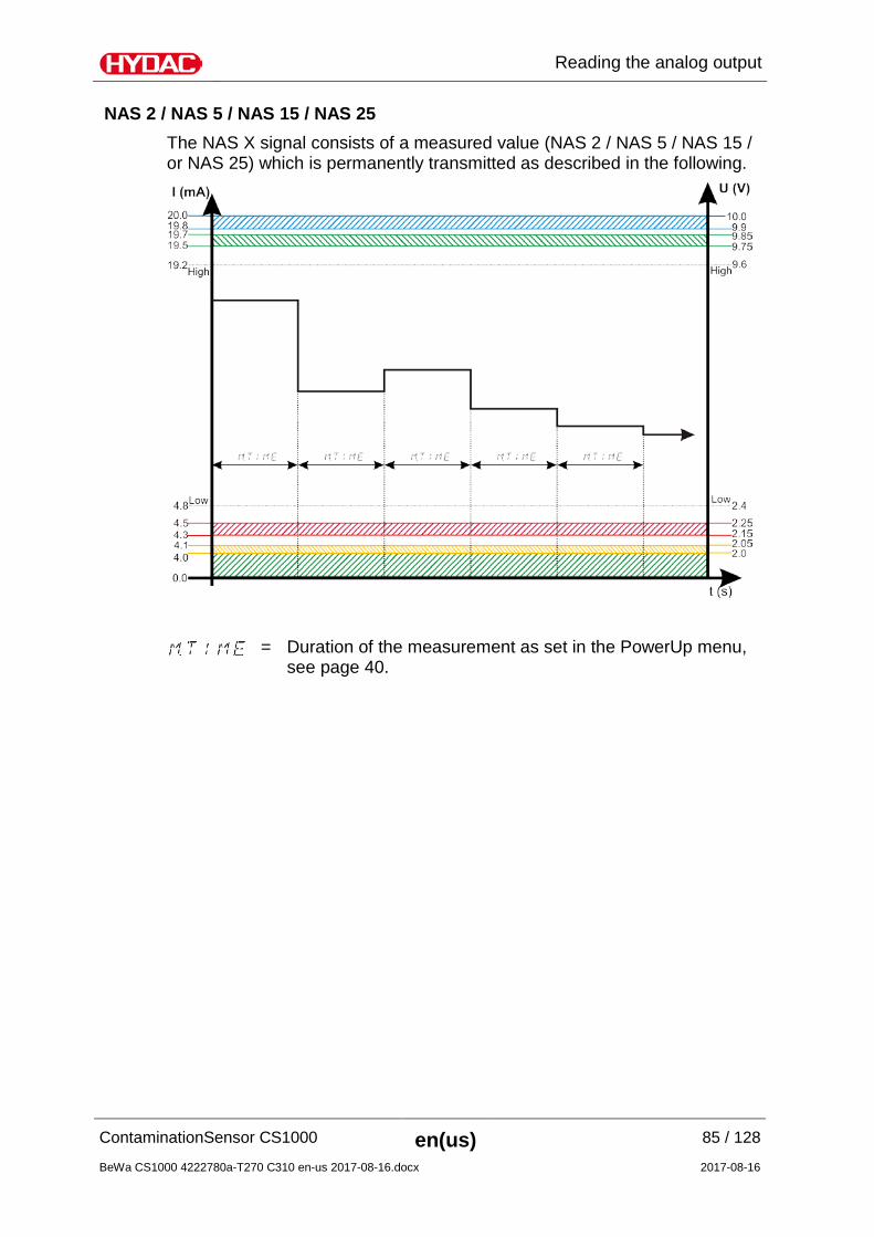
NAS 2 / NAS 5 / NAS 15 / NAS 25 The NAS X signal consists of a measured value (NAS 2 / NAS 5 / NAS 15 / or NAS 25) which is permanently transmitted as described in the following.
= Duration of the measurement as set in the PowerUp menu, see page 40.
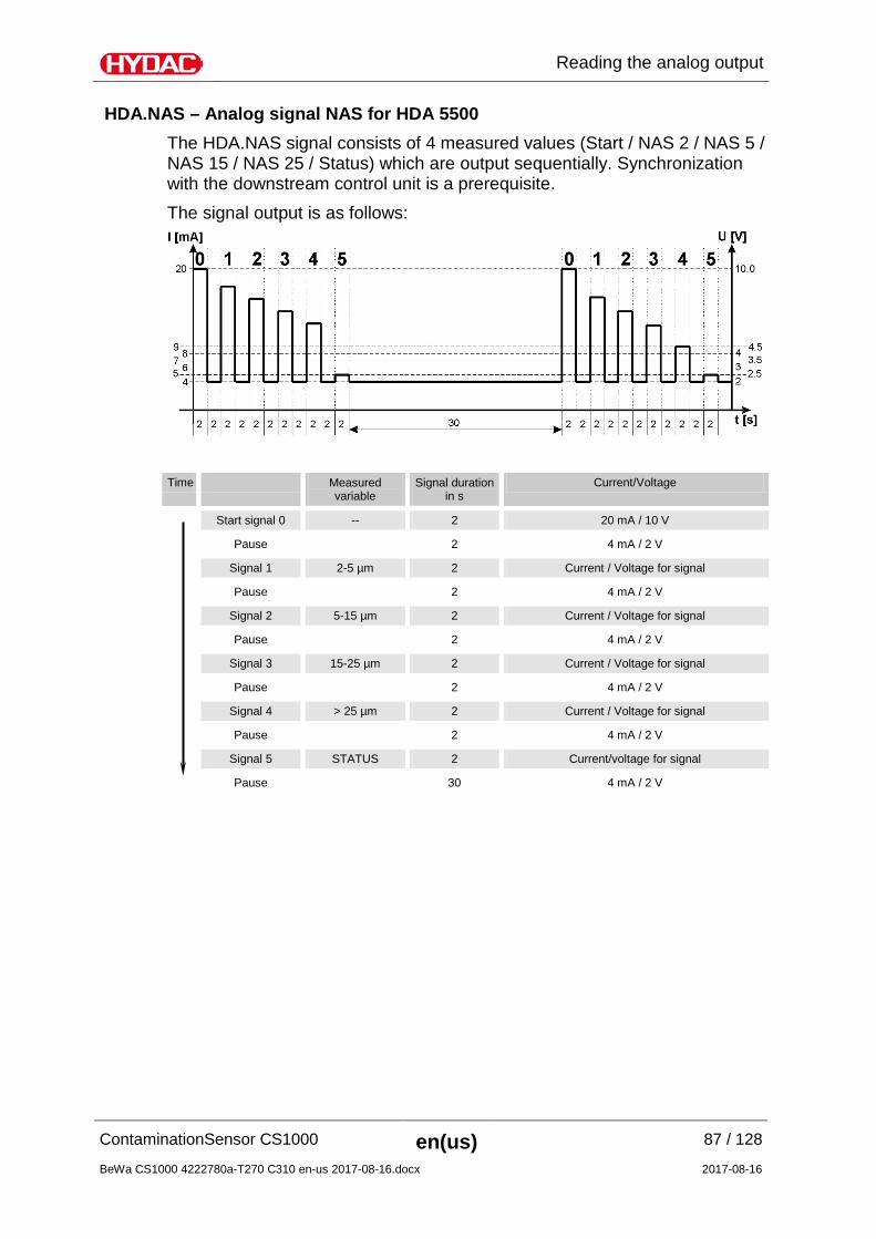
HDA.NAS – Analog signal NAS for HDA 5500 The HDA.NAS signal consists of 4 measured values (Start / NAS 2 / NAS 5 / NAS 15 / NAS 25 / Status) which are output sequentially. Synchronization with the downstream control unit is a prerequisite. The signal output is as follows:
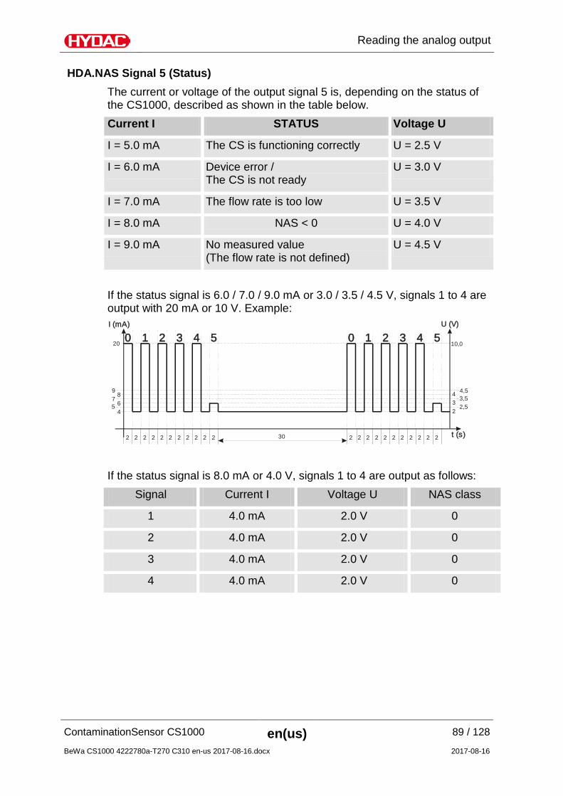
HDA.NAS Signal 5 (Status) The current or voltage of the output signal 5 is, depending on the status of the CS1000, described as shown in the table below. Current I STATUS Voltage U
I = 5.0 mA The CS is functioning correctly U = 2.5 V
I = 6.0 mA Device error / The CS is not ready
U = 3.0 V
I = 7.0 mA The flow rate is too low U = 3.5 V
I = 8.0 mA NAS < 0 U = 4.0 V
I = 9.0 mA No measured value (The flow rate is not defined)
U = 4.5 V
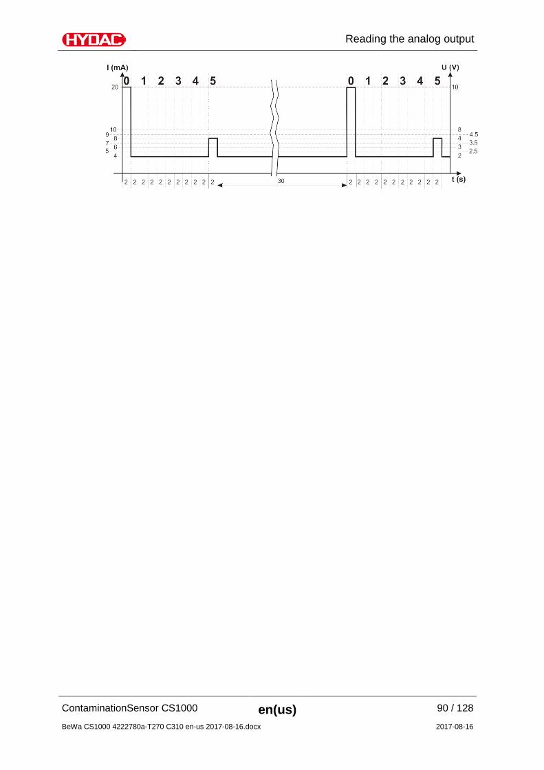
If the status signal is 6.0 / 7.0 / 9.0 mA or 3.0 / 3.5 / 4.5 V, signals 1 to 4 are output with 20 mA or 10 V. Example: I (mA) U (V)
t (s)
4 26 3
9 4,5
10,0
75
3,52,5
8 4
20
2 2 2 2 2 2 2 2 2 2 2 2 2 2 2 2 2 2 2 2 2 230
1 102 23 34 45 50
If the status signal is 8.0 mA or 4.0 V, signals 1 to 4 are output as follows:
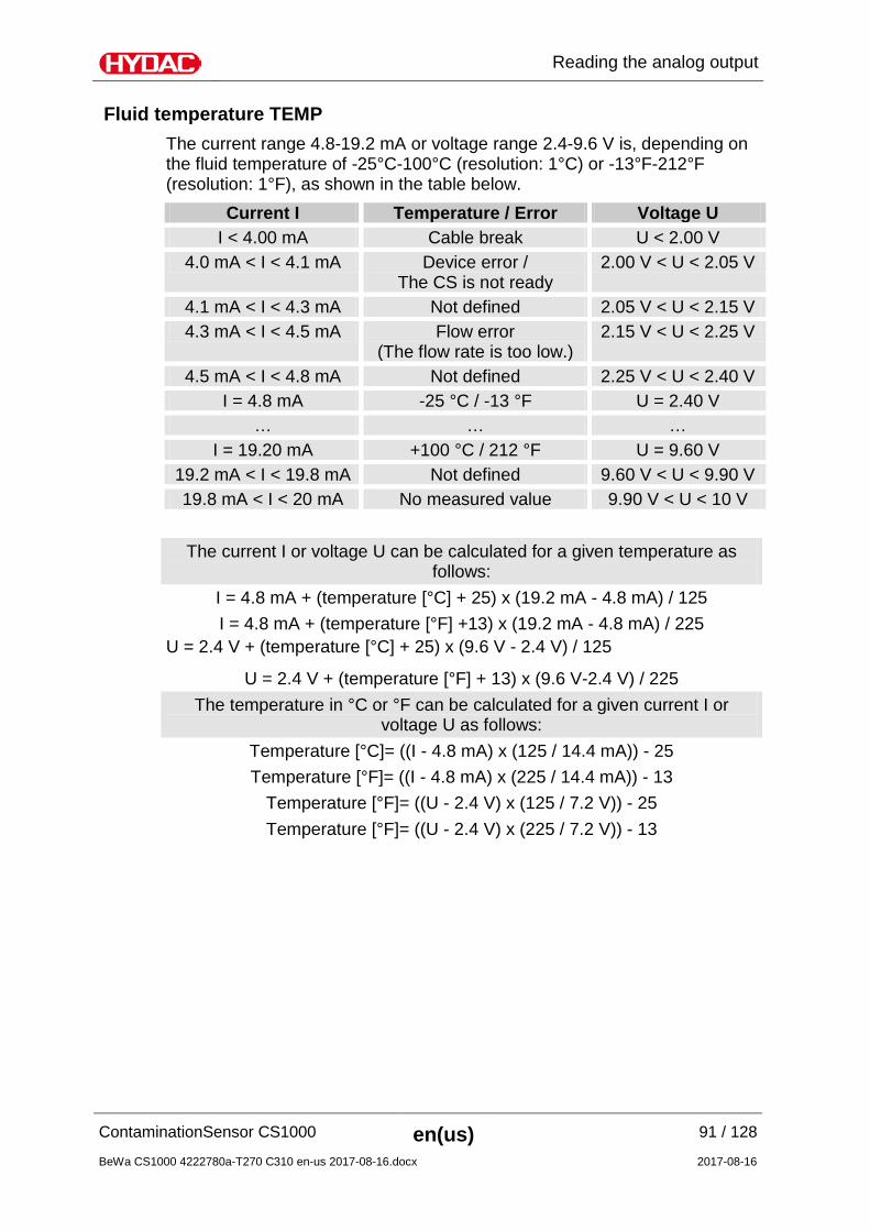
Fluid temperature TEMP The current range 4.8-19.2 mA or voltage range 2.4-9.6 V is, depending on the fluid temperature of -25°C-100°C (resolution: 1°C) or -13°F-212°F (resolution: 1°F), as shown in the table below.
Current I Temperature / Error Voltage U I < 4.00 mA Cable break U < 2.00 V
4.0 mA < I < 4.1 mA Device error / The CS is not ready
2.00 V < U < 2.05 V
4.1 mA < I < 4.3 mA Not defined 2.05 V < U < 2.15 V 4.3 mA < I < 4.5 mA Flow error
(The flow rate is too low.) 2.15 V < U < 2.25 V
4.5 mA < I < 4.8 mA Not defined 2.25 V < U < 2.40 V I = 4.8 mA -25 °C / -13 °F U = 2.40 V
… … … I = 19.20 mA +100 °C / 212 °F U = 9.60 V
19.2 mA < I < 19.8 mA Not defined 9.60 V < U < 9.90 V 19.8 mA < I < 20 mA No measured value 9.90 V < U < 10 V
The current I or voltage U can be calculated for a given temperature as follows:
I = 4.8 mA + (temperature [°C] + 25) x (19.2 mA - 4.8 mA) / 125 I = 4.8 mA + (temperature [°F] +13) x (19.2 mA - 4.8 mA) / 225
U = 2.4 V + (temperature [°C] + 25) x (9.6 V - 2.4 V) / 125
U = 2.4 V + (temperature [°F] + 13) x (9.6 V-2.4 V) / 225 The temperature in °C or °F can be calculated for a given current I or
voltage U as follows: Temperature [°C]= ((I - 4.8 mA) x (125 / 14.4 mA)) - 25 Temperature [°F]= ((I - 4.8 mA) x (225 / 14.4 mA)) - 13
Temperature [°F]= ((U - 2.4 V) x (125 / 7.2 V)) - 25 Temperature [°F]= ((U - 2.4 V) x (225 / 7.2 V)) - 13
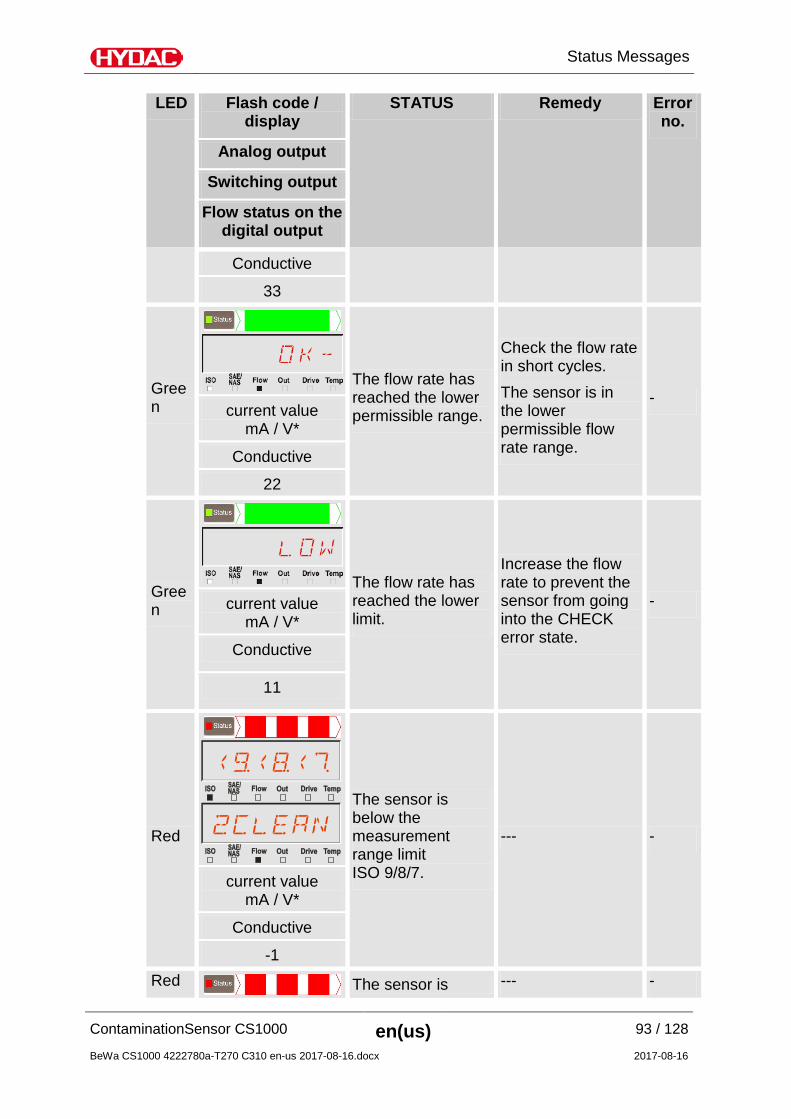
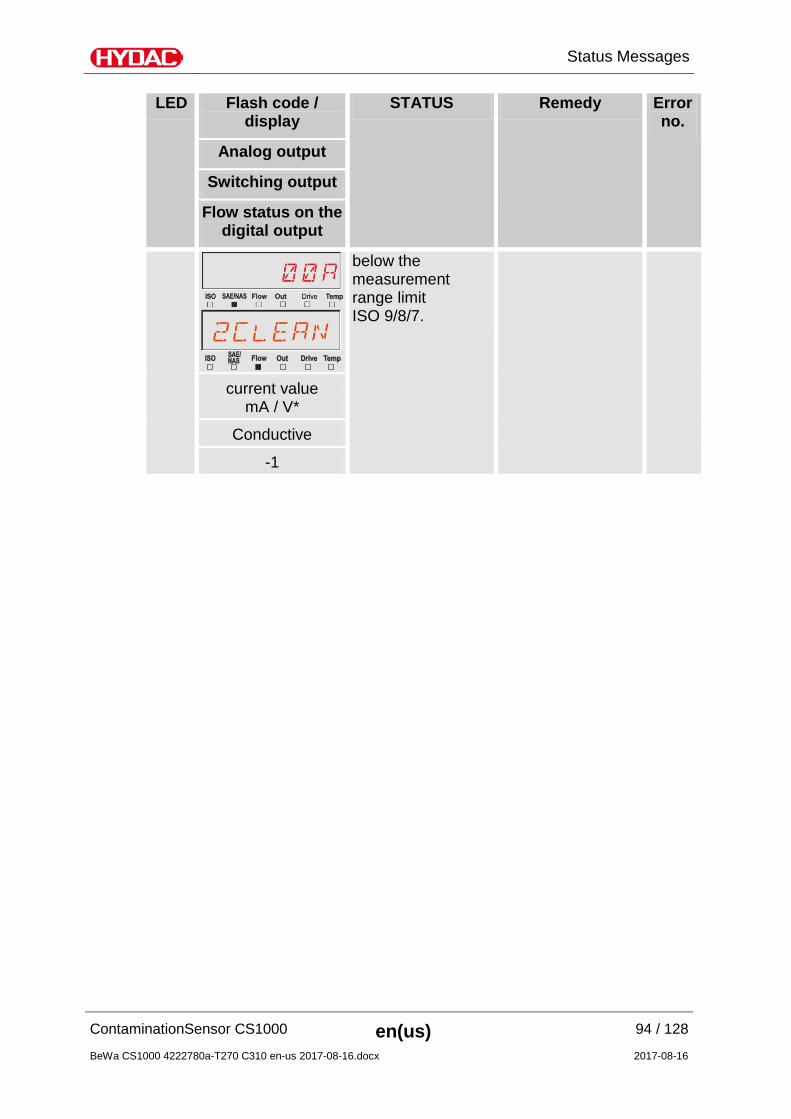
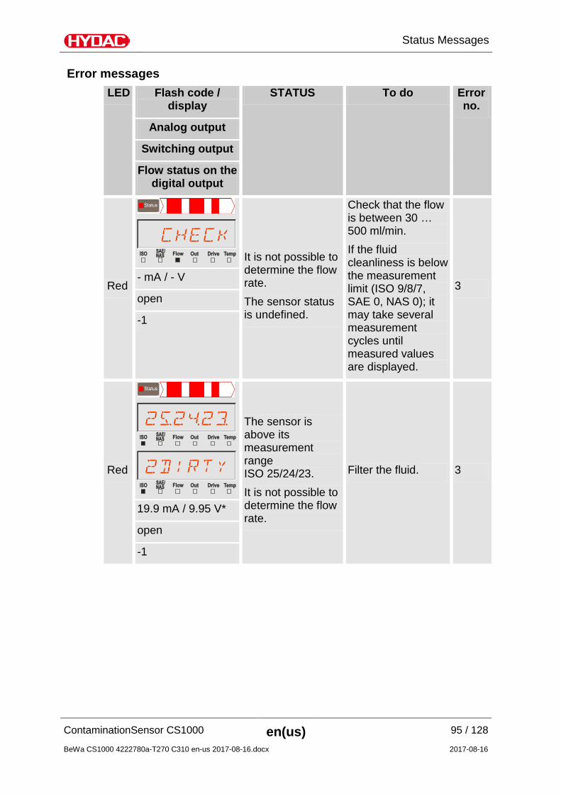
It is not possible to determine the flow rate. The sensor status is undefined.
Check that the flow is between 30 … 500 ml/min. If the fluid cleanliness is below the measurement limit (ISO 9/8/7, SAE 0, NAS 0); it may take several measurement cycles until measured values are displayed.
3 - mA / - V
open
-1
Red
The sensor is above its measurement range ISO 25/24/23. It is not possible to determine the flow rate.
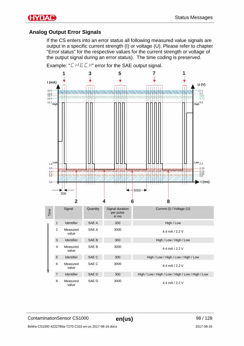
Analog Output Error Signals If the CS enters into an error status all following measured value signals are output in a specific current strength (I) or voltage (U). Please refer to chapter "Error status" for the respective values for the current strength or voltage of the output signal during an error status). The time coding is preserved. Example: " " error for the SAE output signal.
4,0
I (mA) U (V)
t (ms)
4,8Low
20,0
19,2High High
Low
4,54,34,1
19,719,5
3003000
1 3 5 7 1
2 4 6 8
2,02,05
2,25
2,4
9,859,75
2,15
9,6
0,0
19,810,09,9
Tim
e Signal Quantity Signal duration per pulse
in ms
Current (I) / Voltage (U)
1 Identifier SAE A 300 High / Low
2 Measured value
SAE A 3000 4.4 mA / 2.2 V
3 Identifier SAE B 300 High / Low / High / Low
4 Measured value
SAE B 3000 4.4 mA / 2.2 V
5 Identifier SAE C 300 High / Low / High / Low / High / Low
6 Measured value
SAE C 3000 4.4 mA / 2.2 V
7 Identifier SAE D 300 High / Low / High / Low / High / Low / High / Low
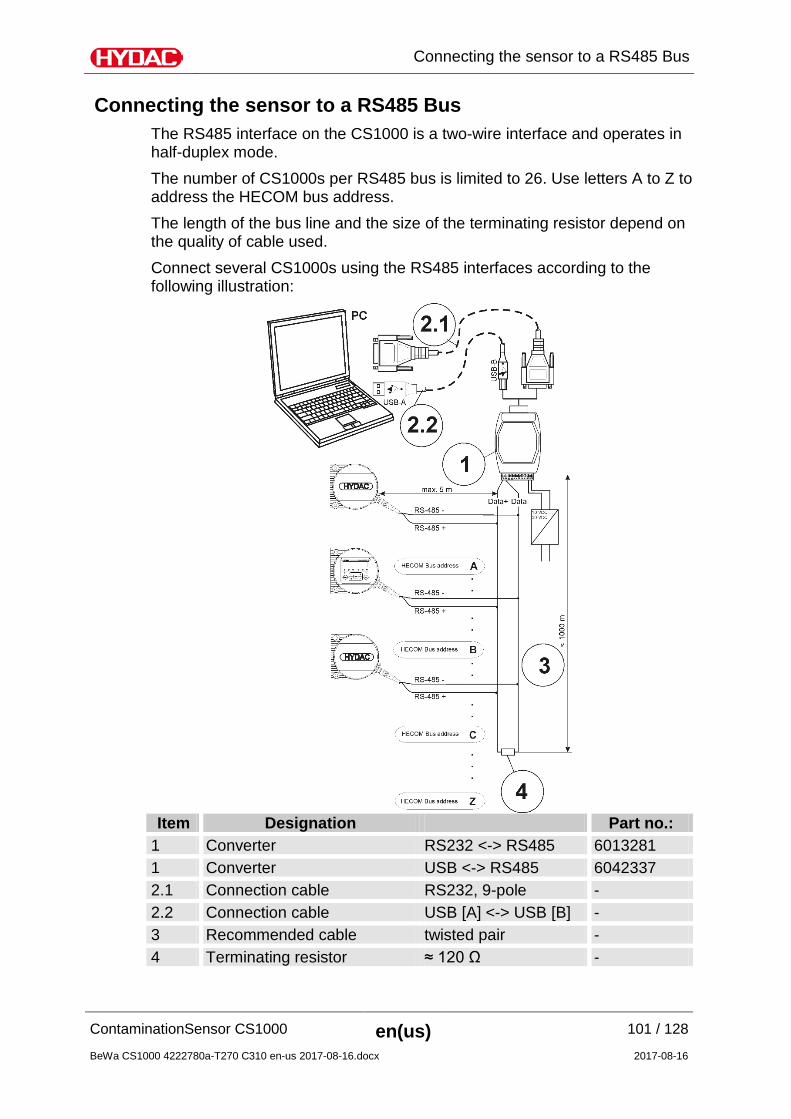
Connecting the sensor to a RS485 Bus The RS485 interface on the CS1000 is a two-wire interface and operates in half-duplex mode. The number of CS1000s per RS485 bus is limited to 26. Use letters A to Z to address the HECOM bus address. The length of the bus line and the size of the terminating resistor depend on the quality of cable used. Connect several CS1000s using the RS485 interfaces according to the following illustration:
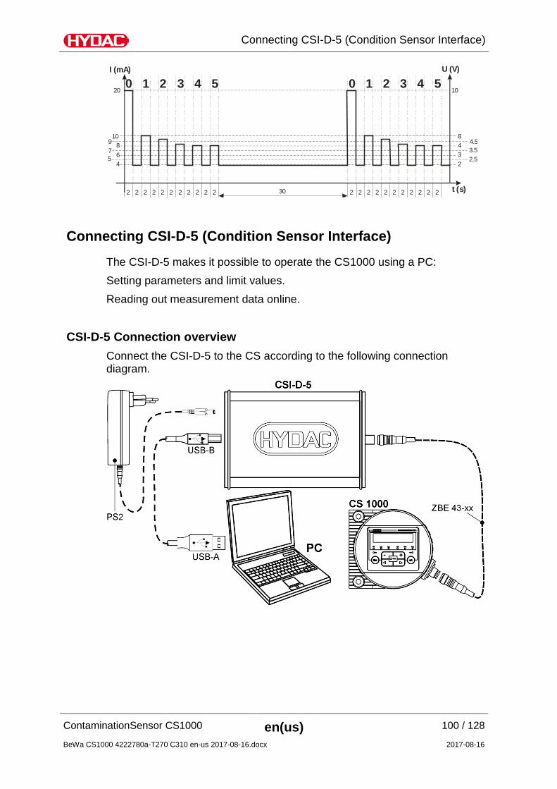
Evaluating/Reading measurement reports with FluMoS
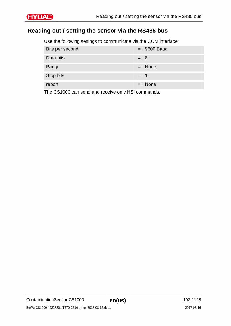
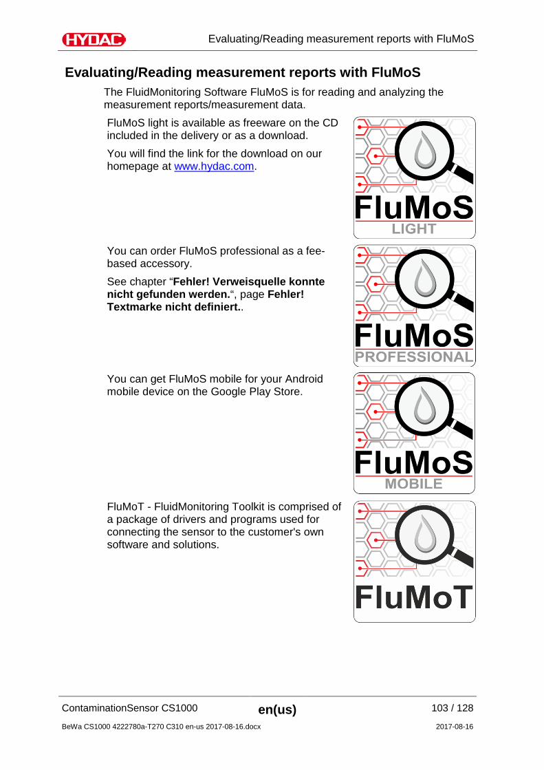
Evaluating/Reading measurement reports with FluMoS The FluidMonitoring Software FluMoS is for reading and analyzing the measurement reports/measurement data. FluMoS light is available as freeware on the CD included in the delivery or as a download. You will find the link for the download on our homepage at www.hydac.com.
You can order FluMoS professional as a fee-based accessory. See chapter “Fehler! Verweisquelle konnte nicht gefunden werden.“, page Fehler! Textmarke nicht definiert..
You can get FluMoS mobile for your Android mobile device on the Google Play Store.
FluMoT - FluidMonitoring Toolkit is comprised of a package of drivers and programs used for connecting the sensor to the customer's own software and solutions.
Perform maintenance The sensor is maintenance-free. Check the calibration cyclically, as described in the "Calibrating the sensor" chapter. Clean the display / control panel regularly, as described in the "Cleaning the display / user interface" chapter.
Calibrating the sensor We recommend recalibrating the sensor every 2-3 years unless otherwise specified at a HYDAC-certified Customer Service or Service Center. Addresses can be found on page 108 or on www.hydac.com.
Cleaning the display / user interface Clean the display / control panel with a clean, moist cloth. Do not use any chemical cleaning agent as these may damage the film attached to the surface of the FCU.
Decommissioning the sensor
To decommission, proceed as follows: 1. Disconnect and remove the electric connection to the sensor 2. Close any shut-off devices in the feed and return lines of the
sensor. 2. Depressurize the unit. 3. Remove the hydraulic connection lines to the sensor. 4. Remove the sensor.
Disposing of the sensor
Dispose of the packaging material in an environmentally friendly manner. After removing the sensor and separating its various materials, dispose of it in an environmentally friendly manner.
Hydac Digital display unit HDA5500-0-2-AC-006 1 909925
Hydac Digital display unit HDA5500-0-2-DC-006 1 909926
You will find other electrical and hydraulic accessories for fluid sensors in our general accessories brochure no. 7.623. This brochure can be downloaded free of charge from our website www.hydac.com.
Product CS = ContaminationSensor series 1 = 1000 Series Contamination code 2 = ISO4406:1999; SAE AS4059 (D)
3 = ISO4406:1987; NAS 1638 ISO4406:1999; SAE AS4059 (D)
Options 1 = without display 2 = with display, continuously variable
rotation by 270°
Fluids 0 = based on mineral oil 1 = for phosphate esters Analog interfaces A = 4 … 20 mA B = 2 … 10 V Switching output 0 = Switch output threshold Digital interface 0 = RS485 Electrical connection 0 = Plug connection M12x1, 8-pin, pin, according to
VDE0627 or IEC61984
Hydraulic connection type 0 = Pipe or hose connection 1 = Flange connection Modification number 000 = Standard
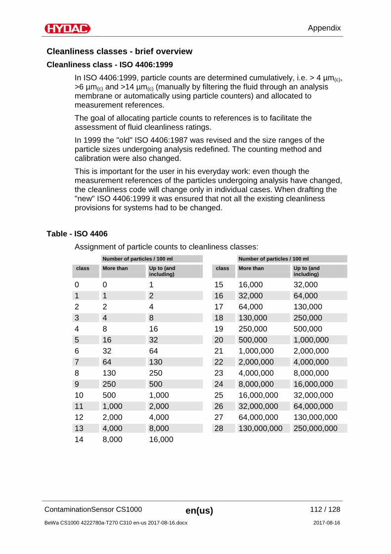
Cleanliness classes - brief overview Cleanliness class - ISO 4406:1999
In ISO 4406:1999, particle counts are determined cumulatively, i.e. > 4 µm(c), >6 µm(c) and >14 µm(c) (manually by filtering the fluid through an analysis membrane or automatically using particle counters) and allocated to measurement references. The goal of allocating particle counts to references is to facilitate the assessment of fluid cleanliness ratings. In 1999 the "old" ISO 4406:1987 was revised and the size ranges of the particle sizes undergoing analysis redefined. The counting method and calibration were also changed. This is important for the user in his everyday work: even though the measurement references of the particles undergoing analysis have changed, the cleanliness code will change only in individual cases. When drafting the "new" ISO 4406:1999 it was ensured that not all the existing cleanliness provisions for systems had to be changed.
Table - ISO 4406 Assignment of particle counts to cleanliness classes: Number of particles / 100 ml Number of particles / 100 ml
Test dust ACFTD - dust 1-10 µm ultra fine fraction
ISO 12103-1A1
SAE Fine, AC – Fine
ISO 12103-1A2
SAE 5-80 µm ISO MTD Calibration dust for particle counters
ISO 12103-1A3
SAE Coarse Coarse fraction
ISO 12103-1A4
Comparable size ranges
Old ACFTD calibration
Comparable ACFTD dusts
New Nist calibration
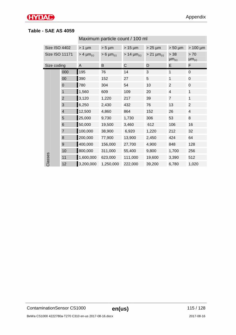
----- < 1 µm 4 µm(c) 5 µm 4.3 µm 6 µm(c) 15 µm 15.5 µm 14 µm(c) Like ISO 4406, SAE AS 4059 describes particle concentrations in fluids. The analysis methods can be applied in the same manner as ISO 4406:1999.
An additional feature in common with ISO 4406:1999 is that cleanliness classes are grouped on the basis of cumulative number of particles (i.e. all particles that are larger than a certain limit value are > 4 µm, for example). As opposed to ISO, SAE AS 4059 uses different limit values among the various particle sizes for contamination classes. For this reason, the corresponding designation of the particle size being examined in the SAE cleanliness classes always has to be added, e.g.:
AS 4059 Class 6B -> 9731 – 19500 particles >6 µm
AS 4059 Class 8A/7B/6C -> 3-value ISO code >4µm/>6µm/>14µm If an SAE class is given acc. to AS 4059 without a letter, then it is always particle size B (> 6 µm). The following table shows the cleanliness classes in relation to the particle concentration determined.
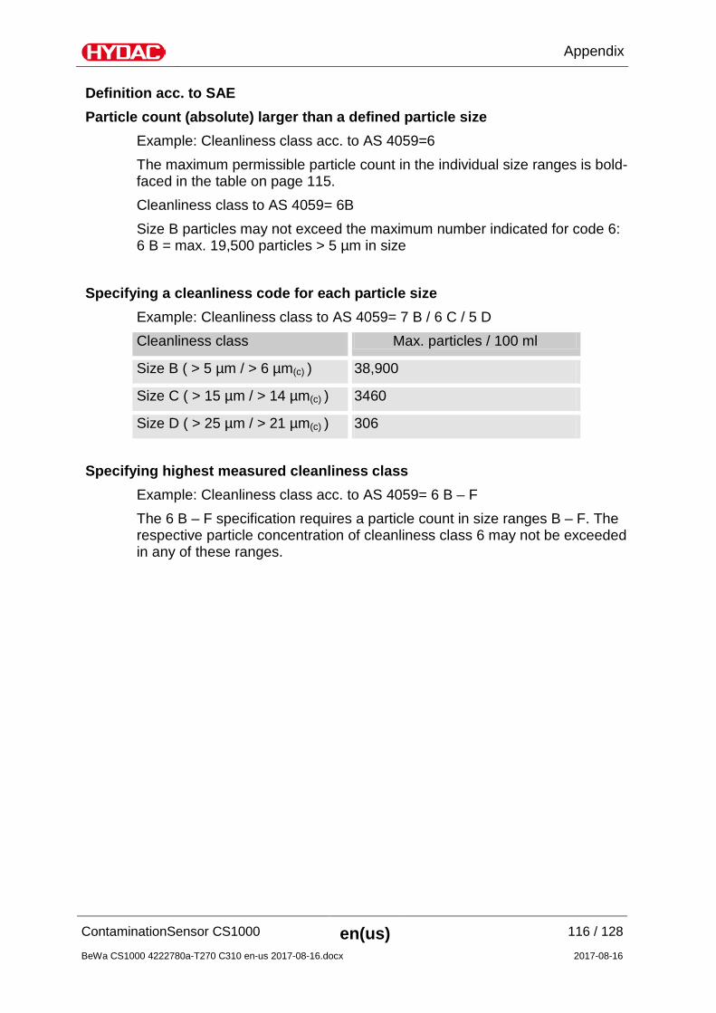
Definition acc. to SAE Particle count (absolute) larger than a defined particle size
Example: Cleanliness class acc. to AS 4059=6 The maximum permissible particle count in the individual size ranges is bold-faced in the table on page 115. Cleanliness class to AS 4059= 6B Size B particles may not exceed the maximum number indicated for code 6: 6 B = max. 19,500 particles > 5 µm in size
Specifying a cleanliness code for each particle size Example: Cleanliness class to AS 4059= 7 B / 6 C / 5 D Cleanliness class Max. particles / 100 ml
Size B ( > 5 µm / > 6 µm(c) ) 38,900
Size C ( > 15 µm / > 14 µm(c) ) 3460
Size D ( > 25 µm / > 21 µm(c) ) 306
Specifying highest measured cleanliness class Example: Cleanliness class acc. to AS 4059= 6 B – F The 6 B – F specification requires a particle count in size ranges B – F. The respective particle concentration of cleanliness class 6 may not be exceeded in any of these ranges.
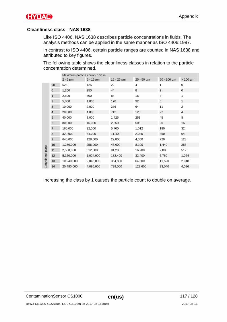
Cleanliness class - NAS 1638 Like ISO 4406, NAS 1638 describes particle concentrations in fluids. The analysis methods can be applied in the same manner as ISO 4406:1987. In contrast to ISO 4406, certain particle ranges are counted in NAS 1638 and attributed to key figures. The following table shows the cleanliness classes in relation to the particle concentration determined. Maximum particle count / 100 ml 2 - 5 µm 5 - 15 µm 15 - 25 µm 25 - 50 µm 50 - 100 µm > 100 µm
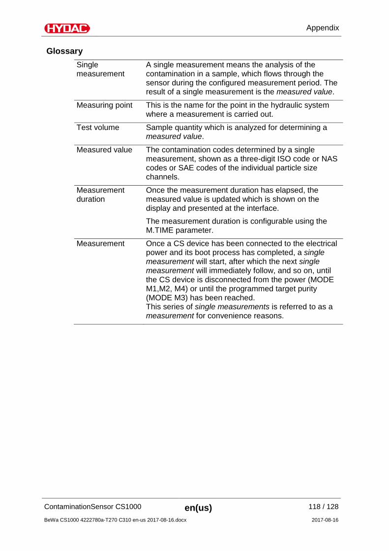
A single measurement means the analysis of the contamination in a sample, which flows through the sensor during the configured measurement period. The result of a single measurement is the measured value.
Measuring point This is the name for the point in the hydraulic system where a measurement is carried out.
Test volume Sample quantity which is analyzed for determining a measured value.
Measured value The contamination codes determined by a single measurement, shown as a three-digit ISO code or NAS codes or SAE codes of the individual particle size channels.
Measurement duration
Once the measurement duration has elapsed, the measured value is updated which is shown on the display and presented at the interface. The measurement duration is configurable using the M.TIME parameter.
Measurement Once a CS device has been connected to the electrical power and its boot process has completed, a single measurement will start, after which the next single measurement will immediately follow, and so on, until the CS device is disconnected from the power (MODE M1,M2, M4) or until the programmed target purity (MODE M3) has been reached. This series of single measurements is referred to as a measurement for convenience reasons.
HYDAC FILTER SYSTEMS GMBHPostfach 12 5166273 Sulzbach / SaarGermany
Industriegebiet66280 Sulzbach / SaarGermany
Telefon: +49 6897 509 01Internet: www.hydac.com
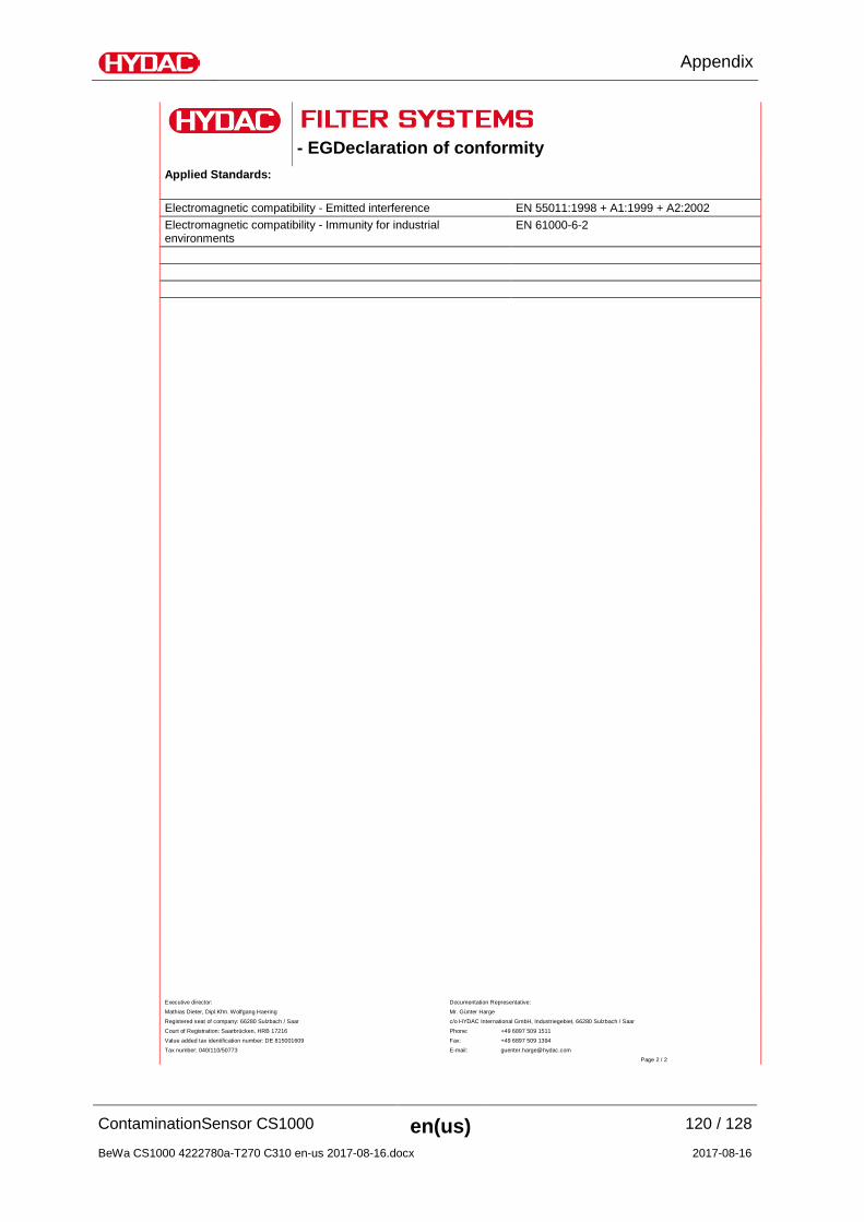
- EGDeclaration of conformity No.
We hereby declare that the following designated product, on the basis of its design and construction, and in the version which we have brought to market, corresponds to the fundamental safety and health requirements contained in the directives and standards listed below.
Any modification of this product that is not coordinated with us in writing will cause this declaration to lose its validity.
Designation ContaminationSensor Type CS1000 series Part no. - Serial no. - Applied directives: EMC directive 2014/30/EU
2016-03-21 M. Eng. (FH) Thorsten Trier Date Name (CE official)
Executive director: Documentation Representative:
Mathias Dieter, Dipl.Kfm. Wolfgang Haering Mr. Günter Harge
Registered seat of company: 66280 Sulzbach / Saar c/o HYDAC International GmbH, Industriegebiet, 66280 Sulzbach / Saar
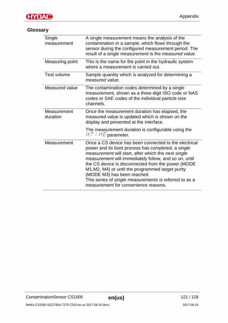
A single measurement means the analysis of the contamination in a sample, which flows through the sensor during the configured measurement period. The result of a single measurement is the measured value.
Measuring point This is the name for the point in the hydraulic system where a measurement is carried out.
Test volume Sample quantity which is analyzed for determining a measured value.
Measured value The contamination codes determined by a single measurement, shown as a three-digit ISO code or NAS codes or SAE codes of the individual particle size channels.
Measurement duration
Once the measurement duration has elapsed, the measured value is updated which is shown on the display and presented at the interface. The measurement duration is configurable using the
parameter.
Measurement Once a CS device has been connected to the electrical power and its boot process has completed, a single measurement will start, after which the next single measurement will immediately follow, and so on, until the CS device is disconnected from the power (MODE M1,M2, M4) or until the programmed target purity (MODE M3) has been reached. This series of single measurements is referred to as a measurement for convenience reasons.