Page 1
4/30/03 ©UCB Spring 2003 CS152 / Kubiatowicz
Lec24.1
CS152Computer Architecture and Engineering
Lecture 24
Buses (continued)Disk IO
Queueing Theory
April 30, 2003
John Kubiatowicz (www.cs.berkeley.edu/~kubitron)
lecture slides: http://inst.eecs.berkeley.edu/~cs152/
Page 2
4/30/03 ©UCB Spring 2003 CS152 / Kubiatowicz
Lec24.2
Recap: Making address translation practical: TLB° Virtual memory => memory acts like a cache for the disk
° Page table maps virtual page numbers to physical frames
° Translation Look-aside Buffer (TLB) is a cache translations
PhysicalMemory Space
Virtual Address Space
TLB
Page Table
2
0
1
3
virtual address
page off
2frame page
250
physical address
page off
Page 3
4/30/03 ©UCB Spring 2003 CS152 / Kubiatowicz
Lec24.3
TLB 4K Cache
10 2
00
4 bytes
index 1 K
page # disp20
assoclookup
32
Hit/Miss
FN Data Hit/Miss
=FN
What if cache size is increased to 8KB?
° If we do this in parallel, we have to be careful, however:
Recap: Overlapped TLB & Cache Access
Page 4
4/30/03 ©UCB Spring 2003 CS152 / Kubiatowicz
Lec24.4
Recap: A Three-Bus System (+ backside cache)
° A small number of backplane buses tap into the processor-memory bus• Processor-memory bus is only used for processor-memory traffic• I/O buses are connected to the backplane bus
° Advantage: loading on the processor bus is greatly reduced
Processor Memory
Processor Memory Bus
BusAdaptor
BusAdaptor
BusAdaptor
I/O Bus
BacksideCache bus
I/O BusL2 Cache
Page 5
4/30/03 ©UCB Spring 2003 CS152 / Kubiatowicz
Lec24.5
Recap: Main components of Intel Chipset: Pentium II/III
° Northbridge:
• Handles memory
• Graphics
° Southbridge: I/O
• PCI bus
• Disk controllers
• USB controlers
• Audio
• Serial I/O
• Interrupt controller
• Timers
Page 6
4/30/03 ©UCB Spring 2003 CS152 / Kubiatowicz
Lec24.6
° Synchronous Bus:
• Includes a clock in the control lines
• A fixed protocol relative to the clock
• Advantage: little logic and very fast
• Disadvantages:
- Every device on the bus must run at the same clock rate
- To avoid clock skew, they cannot be long if they are fast
° Asynchronous Bus:
• It is not clocked
• It can accommodate a wide range of devices
• It can be lengthened without worrying about clock skew
• It requires a handshaking protocol
Synchronous and Asynchronous Bus
Page 7
4/30/03 ©UCB Spring 2003 CS152 / Kubiatowicz
Lec24.7
° Even memory busses are more complex than this
• memory (slave) may take time to respond
• it may need to control data rate
BReq
BG
Cmd+AddrR/WAddress
Data1 Data2Data
Simple Synchronous Protocol
Page 8
4/30/03 ©UCB Spring 2003 CS152 / Kubiatowicz
Lec24.8
° Slave indicates when it is prepared for data xfer
° Actual transfer goes at bus rate
BReq
BG
Cmd+AddrR/WAddress
Data1 Data2Data Data1
Wait
Typical Synchronous Protocol
Page 9
4/30/03 ©UCB Spring 2003 CS152 / Kubiatowicz
Lec24.9
Address
Data
Read
Req
Ack
Master Asserts Address
Master Asserts Data
Next Address
Write Transaction
t0 t1 t2 t3 t4 t5t0 : Master has obtained control and asserts address, direction, data
Waits a specified amount of time for slaves to decode target.
t1: Master asserts request line
t2: Slave asserts ack, indicating data received
t3: Master releases req
t4: Slave releases ack
Asynchronous Write Transaction
Page 10
4/30/03 ©UCB Spring 2003 CS152 / Kubiatowicz
Lec24.10
Address
Data
Read
Req
Ack
Master Asserts Address Next Address
t0 t1 t2 t3 t4 t5
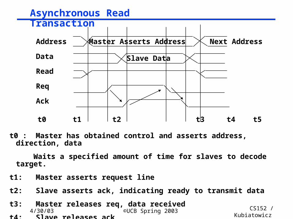
t0 : Master has obtained control and asserts address, direction, data
Waits a specified amount of time for slaves to decode target.
t1: Master asserts request line
t2: Slave asserts ack, indicating ready to transmit data
t3: Master releases req, data received
t4: Slave releases ack
Asynchronous Read Transaction
Slave Data
Page 11
4/30/03 ©UCB Spring 2003 CS152 / Kubiatowicz
Lec24.11
Multiple Potential Bus Masters: the Need for Arbitration
° Bus arbitration scheme:• A bus master wanting to use the bus asserts the bus request• A bus master cannot use the bus until its request is granted• A bus master must signal to the arbiter after finish using the bus
° Bus arbitration schemes usually try to balance two factors:• Bus priority: the highest priority device should be serviced first• Fairness: Even the lowest priority device should never
be completely locked out from the bus° Bus arbitration schemes can be divided into four broad classes:
• Daisy chain arbitration• Centralized, parallel arbitration• Distributed arbitration by self-selection: each device wanting the bus places a code
indicating its identity on the bus.• Distributed arbitration by collision detection:
Each device just “goes for it”. Problems found after the fact.
Page 12
4/30/03 ©UCB Spring 2003 CS152 / Kubiatowicz
Lec24.12
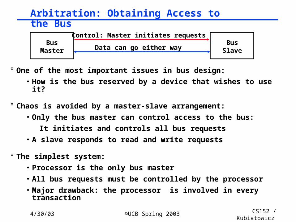
° One of the most important issues in bus design:
• How is the bus reserved by a device that wishes to use it?
° Chaos is avoided by a master-slave arrangement:
• Only the bus master can control access to the bus:
It initiates and controls all bus requests
• A slave responds to read and write requests
° The simplest system:
• Processor is the only bus master
• All bus requests must be controlled by the processor
• Major drawback: the processor is involved in every transaction
BusMaster
BusSlave
Control: Master initiates requests
Data can go either way
Arbitration: Obtaining Access to the Bus
Page 13
4/30/03 ©UCB Spring 2003 CS152 / Kubiatowicz
Lec24.13
The Daisy Chain Bus Arbitrations Scheme
° Advantage: simple
° Disadvantages:
• Cannot assure fairness: A low-priority device may be locked out indefinitely
• The use of the daisy chain grant signal also limits the bus speed
BusArbiter
Device 1HighestPriority
Device NLowestPriority
Device 2
Grant Grant Grant
Release
Request
wired-OR
Page 14
4/30/03 ©UCB Spring 2003 CS152 / Kubiatowicz
Lec24.14
° Used in essentially all processor-memory busses and in high-speed I/O busses
BusArbiter
Device 1 Device NDevice 2
Grant Req
Centralized Parallel Arbitration
Page 15
4/30/03 ©UCB Spring 2003 CS152 / Kubiatowicz
Lec24.15
° Separate versus multiplexed address and data lines:• Address and data can be transmitted in one bus cycle
if separate address and data lines are available
• Cost: (a) more bus lines, (b) increased complexity
° Data bus width:• By increasing the width of the data bus, transfers of multiple words require fewer
bus cycles
• Example: SPARCstation 20’s memory bus is 128 bit wide
• Cost: more bus lines
° Block transfers:• Allow the bus to transfer multiple words in back-to-back bus cycles
• Only one address needs to be sent at the beginning
• The bus is not released until the last word is transferred
• Cost: (a) increased complexity (b) decreased response time for request
Increasing the Bus Bandwidth
Page 16
4/30/03 ©UCB Spring 2003 CS152 / Kubiatowicz
Lec24.16
° Overlapped arbitration• perform arbitration for next transaction during current transaction
° Bus parking• master can holds onto bus and performs multiple transactions as long
as no other master makes request
° Overlapped address / data phases (prev. slide)• requires one of the above techniques
° Split-phase (or packet switched) bus• completely separate address and data phases
• arbitrate separately for each
• address phase yield a tag which is matched with data phase
° ”All of the above” in most modern buses
Increasing Transaction Rate on Multimaster Bus
Page 17
4/30/03 ©UCB Spring 2003 CS152 / Kubiatowicz
Lec24.17
° All signals sampled on rising edge
° Centralized Parallel Arbitration• overlapped with previous transaction
° All transfers are (unlimited) bursts
° Address phase starts by asserting FRAME#
° Next cycle “initiator” asserts cmd and address
° Data transfers happen when• IRDY# asserted by master when ready to transfer data
• TRDY# asserted by target when ready to transfer data
• transfer when both asserted on rising edge
° FRAME# deasserted when master intends to complete only one more data transfer
PCI Read/Write Transactions
Page 18
4/30/03 ©UCB Spring 2003 CS152 / Kubiatowicz
Lec24.18
– Turn-around cycle on any signal driven by more than one agent
PCI Read Transaction
Page 19
4/30/03 ©UCB Spring 2003 CS152 / Kubiatowicz
Lec24.19
PCI Write Transaction
Page 20
4/30/03 ©UCB Spring 2003 CS152 / Kubiatowicz
Lec24.20
° Push bus efficiency toward 100% under common usage° Bus Parking
• retain bus grant for previous master until another makes request• granted master can start next transfer without arbitration
° Arbitrary Burst length• initiator and target can exert flow control with xRDY• target can disconnect request with STOP (abort or retry)• master can disconnect by deasserting FRAME• arbiter can disconnect by deasserting GNT
° Delayed (pended, split-phase) transactions• free the bus after request to slow device
PCI Optimizations
Page 21
4/30/03 ©UCB Spring 2003 CS152 / Kubiatowicz
Lec24.21
Administrivia
° Get going on Lab 7!• Status update due Thursday in Section• Talk with TAs about the state of your project• Remember: simplicity is better than complexity!
- Every year, people get over ambitious- Much better to make things work!
° Midterm II on Monday• 5:30 – 8:30 in 306 Soda Hall
- Pizza afterwards• Review Session Sunday in 306, 7:00 – 9:00• Topics
- Pipelining- Caches/Memory systems- Buses and I/O (Disk equation)- Queueing theory
• Can bring 1 page of notes and calculator- Handwitten, double-sided- CLOSED BOOK!
Page 22
4/30/03 ©UCB Spring 2003 CS152 / Kubiatowicz
Lec24.22
Computers in the News: Sony Playstation 2000
° (as reported in Microprocessor Report, Vol 13, No. 5)• Emotion Engine: 6.2 GFLOPS, 75 million polygons per second
• Graphics Synthesizer: 2.4 Billion pixels per second
• Claim: Toy Story realism brought to games!
Page 23
4/30/03 ©UCB Spring 2003 CS152 / Kubiatowicz
Lec24.23
Playstation 2000 Continued
° Sample Vector Unit
• 2-wide VLIW
• Includes Microcode Memory
• High-level instructions like matrix-multiply
° Emotion Engine:
• Superscalar MIPS core
• Vector Coprocessor Pipelines
• RAMBUS DRAM interface
Page 24
4/30/03 ©UCB Spring 2003 CS152 / Kubiatowicz
Lec24.24
I/O Device Examples
Device Behavior Partner Data Rate (KB/sec)
Keyboard Input Human 0.01
Mouse Input Human 0.02
Line Printer Output Human 1.00
Floppy disk Storage Machine 50.00
Laser Printer Output Human 100.00
Optical Disk Storage Machine 500.00
Magnetic Disk Storage Machine 5,000.00
Network-LAN Input or Output Machine 20 – 1,000.00
Graphics Display Output Human 30,000.00
Page 25
4/30/03 ©UCB Spring 2003 CS152 / Kubiatowicz
Lec24.25
I/O System Performance
° I/O System performance depends on many aspects of the system (“limited by weakest link in the chain”):
• The CPU
• The memory system:
- Internal and external caches
- Main Memory
• The underlying interconnection (buses)
• The I/O controller
• The I/O device
• The speed of the I/O software (Operating System)
• The efficiency of the software’s use of the I/O devices
° Two common performance metrics:
• Throughput: I/O bandwidth
• Response time: Latency
Page 26
4/30/03 ©UCB Spring 2003 CS152 / Kubiatowicz
Lec24.26
Simple Producer-Server Model
° Throughput:
• The number of tasks completed by the server in unit time
• In order to get the highest possible throughput:
- The server should never be idle
- The queue should never be empty
° Response time:
• Begins when a task is placed in the queue
• Ends when it is completed by the server
• In order to minimize the response time:
- The queue should be empty
- The server will be idle
Producer ServerQueue
Page 27
4/30/03 ©UCB Spring 2003 CS152 / Kubiatowicz
Lec24.27
Throughput versus Respond Time
20% 40% 60% 80% 100%
ResponseTime (ms)
100
200
300
Percentage of maximum throughput
Page 28
4/30/03 ©UCB Spring 2003 CS152 / Kubiatowicz
Lec24.28
Throughput Enhancement
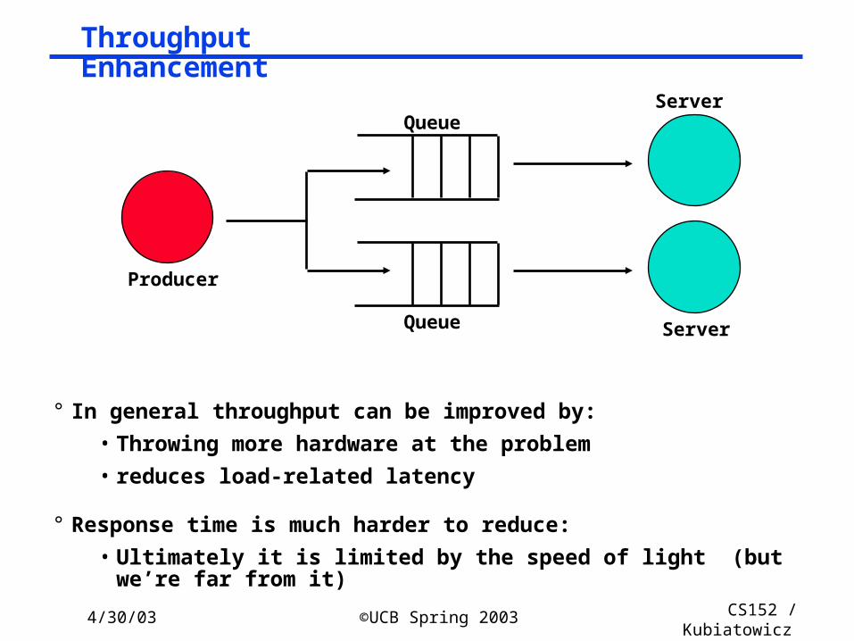
° In general throughput can be improved by:
• Throwing more hardware at the problem
• reduces load-related latency
° Response time is much harder to reduce:
• Ultimately it is limited by the speed of light (but we’re far from it)
Producer
ServerQueue
QueueServer
Page 29
4/30/03 ©UCB Spring 2003 CS152 / Kubiatowicz
Lec24.29
Disk Capacity now doubles every 18 months; before1990 every 36 months
• Today: Processing Power Doubles Every 18 months
• Today: Memory Size Doubles Every 18 months(4X/3yr)
• Today: Disk Capacity Doubles Every 18 months
• Disk Positioning Rate (Seek + Rotate) Doubles Every Ten Years!
The I/OGAP
The I/OGAP
Technology Trends
Page 30
4/30/03 ©UCB Spring 2003 CS152 / Kubiatowicz
Lec24.30
Data densityMbit/sq. in.
Capacity ofUnit ShownMegabytes
1973:1. 7 Mbit/sq. in140 MBytes
1979:7. 7 Mbit/sq. in2,300 MBytes
source: New York Times, 2/23/98, page C3, “Makers of disk drives crowd even mroe data into even smaller spaces”
Disk History
Page 31
4/30/03 ©UCB Spring 2003 CS152 / Kubiatowicz
Lec24.31
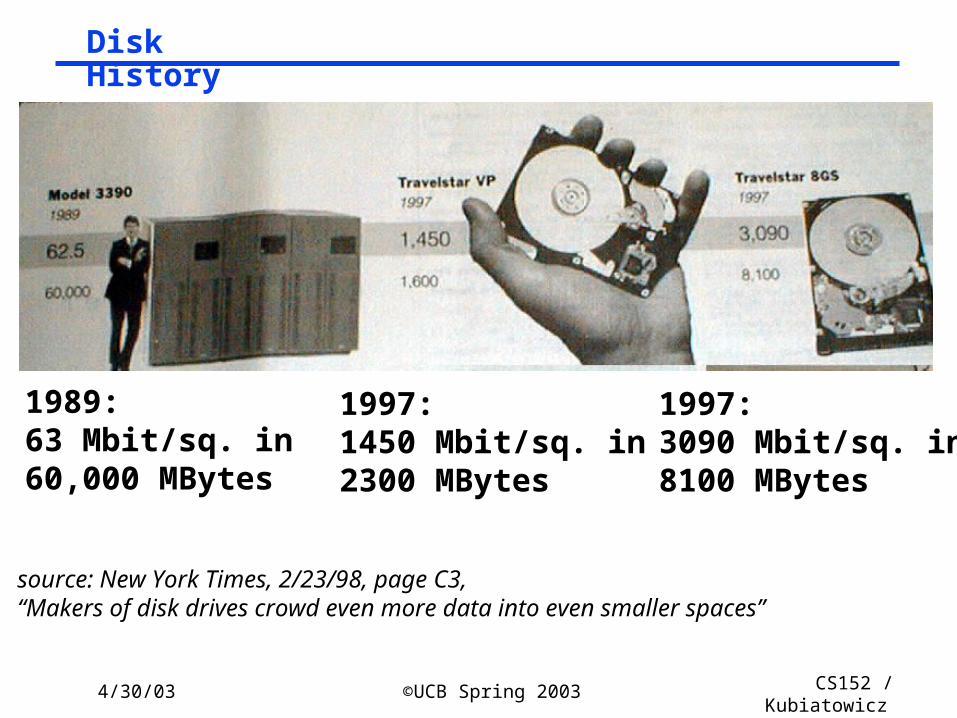
1989:63 Mbit/sq. in60,000 MBytes
1997:1450 Mbit/sq. in2300 MBytes
source: New York Times, 2/23/98, page C3, “Makers of disk drives crowd even more data into even smaller spaces”
1997:3090 Mbit/sq. in8100 MBytes
Disk History
Page 32
4/30/03 ©UCB Spring 2003 CS152 / Kubiatowicz
Lec24.32
0%
5%
10%
15%
20%
25%
30%
35%
40%
1974 1980 1986 1992 1998
source: New York Times, 2/23/98, page C3, “Makers of disk drives crowd even more data into even smaller spaces”
470 v. 3000 Mb/si
9 v. 22 Mb/si
0.2 v. 1.7 Mb/si
MBits per square inch: DRAM as % of Disk over time
Page 33
4/30/03 ©UCB Spring 2003 CS152 / Kubiatowicz
Lec24.33
Nano-layered Disk Heads
° Special sensitivity of Disk head comes from “Giant Magneto-Resistive effect” or (GMR)
° IBM is leader in this technology• Same technology as TMJ-RAM breakthrough we described in
earlier class.
Coil for writing
Page 34
4/30/03 ©UCB Spring 2003 CS152 / Kubiatowicz
Lec24.34
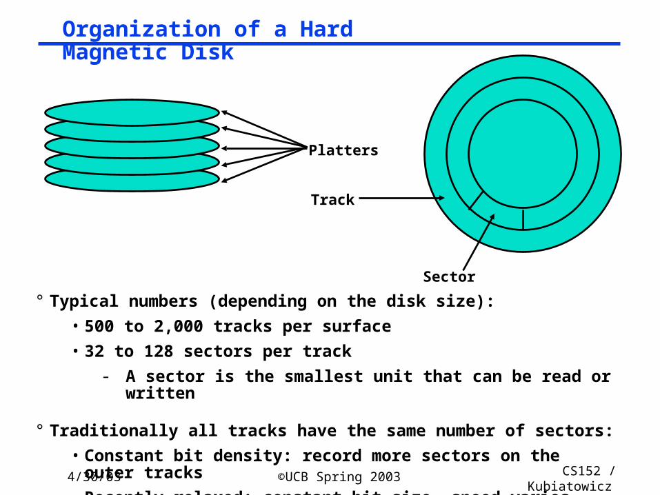
Organization of a Hard Magnetic Disk
° Typical numbers (depending on the disk size):
• 500 to 2,000 tracks per surface
• 32 to 128 sectors per track
- A sector is the smallest unit that can be read or written
° Traditionally all tracks have the same number of sectors:
• Constant bit density: record more sectors on the outer tracks
• Recently relaxed: constant bit size, speed varies with track location
Platters
Track
Sector
Page 35
4/30/03 ©UCB Spring 2003 CS152 / Kubiatowicz
Lec24.35
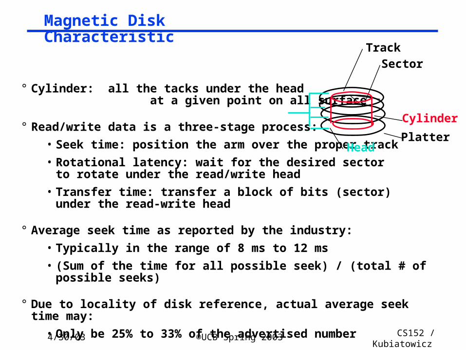
Magnetic Disk Characteristic
° Cylinder: all the tacks under the head at a given point on all surface
° Read/write data is a three-stage process:
• Seek time: position the arm over the proper track
• Rotational latency: wait for the desired sectorto rotate under the read/write head
• Transfer time: transfer a block of bits (sector)under the read-write head
° Average seek time as reported by the industry:
• Typically in the range of 8 ms to 12 ms
• (Sum of the time for all possible seek) / (total # of possible seeks)
° Due to locality of disk reference, actual average seek time may:
• Only be 25% to 33% of the advertised number
SectorTrack
Cylinder
HeadPlatter
Page 36
4/30/03 ©UCB Spring 2003 CS152 / Kubiatowicz
Lec24.36
Typical Numbers of a Magnetic Disk
° Average seek time as reported by the industry:• Typically in the range of 8 ms to 12 ms• Due to locality of disk reference may
only be 25% to 33% of the advertised number
° Rotational Latency:• Most disks rotate at 3,600 to 7200 RPM (Up to 15,000RPM or more)• Approximately 16 ms to 8 ms
per revolution, respectively• An average latency to the desired
information is halfway around the disk: 8 ms at 3600 RPM, 4 ms at 7200 RPM
° Transfer Time is a function of :• Transfer size (usually a sector): 1 KB / sector• Rotation speed: 3600 RPM to 10000 RPM• Recording density: bits per inch on a track• Diameter typical diameter ranges from 2.5 to 5.25 in• Typical values: 2 to 40 MB per second
SectorTrack
Cylinder
HeadPlatter
Page 37
4/30/03 ©UCB Spring 2003 CS152 / Kubiatowicz
Lec24.37
Disk I/O Performance
° Disk Access Time = Seek time + Rotational Latency + Transfer time
+ Controller Time + Queueing Delay
° Estimating Queue Length:
• Utilization = U = Request Rate / Service Rate= / • Mean Queue Length = U / (1 - U)
• As Request Rate -> Service Rate
- Mean Queue Length -> Infinity
ProcessorQueue
DiskController
Disk
Service RateRequest Rate
Queue
DiskController
Disk
Page 38
4/30/03 ©UCB Spring 2003 CS152 / Kubiatowicz
Lec24.38
Example
° 512 byte sector, rotate at 5400 RPM, advertised seeks is 12 ms, transfer rate is 4 MB/sec, controller overhead is 1 ms, queue idle so no service time
° Disk Access Time = Seek time + Rotational Latency + Transfer time
+ Controller Time + Queueing Delay
° Disk Access Time = 12 ms + 0.5 / 5400 RPM + 0.5 KB / 4 MB/s + 1 ms + 0
° Disk Access Time = 12 ms + 0.5 / 90 RPS + 0.125 / 1024 s + 1 ms + 0
° Disk Access Time = 12 ms + 5.5 ms + 0.1 ms + 1 ms + 0 ms
° Disk Access Time = 18.6 ms
° If real seeks are 1/3 advertised seeks, then its 10.6 ms, with rotation delay at 50% of the time!
Page 39
4/30/03 ©UCB Spring 2003 CS152 / Kubiatowicz
Lec24.39
Reliability and Availability
° Two terms that are often confused:
• Reliability: Is anything broken?
• Availability: Is the system still available to the user?
° Availability can be improved by adding hardware:
• Example: adding ECC on memory
° Reliability can only be improved by:
• Better environmental conditions
• Building more reliable components
• Building with fewer components
- Improve availability may come at the cost of lower reliability
Page 40
4/30/03 ©UCB Spring 2003 CS152 / Kubiatowicz
Lec24.40
Simple Producer-Server Model
° Throughput:
• The number of tasks completed by the server in unit time
• In order to get the highest possible throughput:
- The server should never be idle
- The queue should never be empty
° Response time:
• Begins when a task is placed in the queue
• Ends when it is completed by the server
• In order to minimize the response time:
- The queue should be empty
- The server will be idle
Producer ServerQueue
Page 41
4/30/03 ©UCB Spring 2003 CS152 / Kubiatowicz
Lec24.41
Disk I/O Performance
Response time = Queue + Device Service time
100%
ResponseTime (ms)
Throughput (% total BW)
0
100
200
300
0%
Proc
Queue
IOC Device
Metrics: Response Time Throughput
latency goes as Tser×u/(1-u) u = utilization
Page 42
4/30/03 ©UCB Spring 2003 CS152 / Kubiatowicz
Lec24.42
Bus Summary
° Buses are an important technique for building large-scale systems
• Their speed is critically dependent on factors such as length, number of devices, etc.
• Critically limited by capacitance• Tricks: esoteric drive technology such as GTL
° Important terminology:• Master: The device that can initiate new transactions• Slaves: Devices that respond to the master
° Two types of bus timing:• Synchronous: bus includes clock• Asynchronous: no clock, just REQ/ACK strobing
° Direct Memory Access (DMA) allows fast, burst transfer into processor’s memory:
• Processor’s memory acts like a slave• Probably requires some form of cache-coherence so that DMA’ed
memory can be invalidated from cache.
Page 43
4/30/03 ©UCB Spring 2003 CS152 / Kubiatowicz
Lec24.43
I/O Summary:
° I/O performance limited by weakest link in chain between OS and device
° Three Components of Disk Access Time:• Seek Time: advertised to be 8 to 12 ms. May be lower in real life.
• Rotational Latency: 4.1 ms at 7200 RPM and 8.3 ms at 3600 RPM
• Transfer Time: 2 to 12 MB per second
° I/O device notifying the operating system:• Polling: it can waste a lot of processor time
• I/O interrupt: similar to exception except it is asynchronous
° Delegating I/O responsibility from the CPU: • DMA, or even IOP