CS4670 Final Report Hand Gesture Detection and Recognition for Human-Computer Interaction By, Roopashree H Sreenivasa Rao (rhs229) Jonathan Hirschberg (jah477) Index: I. Abstract II. Overview III. Design IV. Constraints V. Sample images contained in the database VI. Results obtained on Desktop VII. Results obtained on Cell Phone VIII. Conclusion IX. Future Work X. Program Description XI. OpenCV functions used XII. Self-Implemented functions XIII. Distribution of Work XIV. Platform XV. Outside Sources XVI. Program Listing
Transcript
CS4670 Final Report
Hand Gesture Detection and Recognition for
Human-Computer Interaction
By,
Roopashree H Sreenivasa Rao (rhs229)
Jonathan Hirschberg (jah477)
Index:
I. Abstract
II. Overview
III. Design
IV. Constraints
V. Sample images contained in the database
VI. Results obtained on Desktop
VII. Results obtained on Cell Phone
VIII. Conclusion
IX. Future Work
X. Program Description
XI. OpenCV functions used
XII. Self-Implemented functions
XIII. Distribution of Work
XIV. Platform
XV. Outside Sources
XVI. Program Listing
I. Abstract:
This project deals with the detection and recognition of hand gestures. Images of the
hand gestures are taken using a Nokia N900 cell phone and matched with the
images in the database and the best match is returned. Gesture recognition is one of
the essential techniques to build user-friendly interfaces. For example, a robot that
can recognize hand gestures can take commands from humans, and for those who
are unable to speak or hear, having a robot that can recognize sign language would
allow them to communicate with it. Hand gesture recognition could help in video
gaming by allowing players to interact with the game using gestures instead of using
a controller. However, such an algorithm needs to be more robust to account for the
myriad of possible hand positions in three-dimensional space. It also needs to work
with video rather than static images. That is beyond the scope of our project.
II. Overview:
Distance Transform: The distance transform is an operator normally only applied to
binary images. The result of the transform is a grayscale image that looks similar to
the input image, except that the intensities of points inside foreground regions are
changed to show the distance to the closest boundary from each point.
For example,
Image was taken from “Distance Transform.” David Coeurjolly.
In the above image, each pixel p of the object is labeled by the distance to the closest
point q in the background.
Contours: Contours are sequences of points defining a line/curve in an image.
Contour matching can be used to classify image objects.
Database: Contains the images of various hand gestures.
Moments: Image moments are useful to describe objects after segmentation. Simple
properties of the image, which are found via image moments, include area (or total
intensity), its centroid and information about its orientation.
Ratio of the two distance transformed images of the same size = (No of pixels whose
difference is zero or less than a certain threshold) / (Total number of pixels in the
distance transformed image)
III. Design:
Step 1: User takes a picture of the hand to be tested either through the cell phone
camera or from the Internet.
Step 2: The image is converted into gray scale and smoothed using a Gaussian
kernel.
Step 3: Convert the gray scale image into a binary image. Set a threshold so that the
pixels that are above a certain intensity are set to white and those below are set to
black.
Step 4: Find contours, then remove noise and smooth the edges to smooth big
contours and melt numerous small contours.
Step 5: The largest contour is selected as a target.
Step 6: The angles of inclination of the contours and also the location of the center of
the contour with respect to the center of the image are obtained through the
bounding box information around the contour.
Step 7: The hand contours inside the bounding boxes are extracted and rotated in
such a way that the bounding boxes are made upright (inclination angle is 0) so that
matching becomes easy.
Step 8: Both the images are scaled so that their widths are set to the greater of the
two widths and their heights are set to the greater of the two heights. This is done
so that the images are the same size.
Step 9: The distance transform of both the query image and the candidate images
are computed and the best match is returned.
IV. Constraints:
1. The picture of the hand must be taken against a dark background
2. The program recognizes a limited number of gestures as long as there are
gestures similar to them in the database.
3. We must have each gesture with at least four orientations at 90 degrees each to
return the best match.
V. Sample Images contained in the Database:
In our experiment, we will be identifying limited number of gestures, which is
shown as below. The query image even with slight orientation (+ or – 30 degrees)
will be able to match with one of the image contained in the database.
Images with different orientations are present within the database. In order to
maintain performance, we have a limited number of gesture images in our database.
New gesture images can be added to the database without any pre-processing.
(a) Few of the images in the database.
VI. Results:
Case 1:
(A)
In the above case, we can see the query image on the left hand side and the matched
candidate image from the database on the right.
(a) Candidate Image in the database
Both the images are converted to binary images and the contours are computed.
Using the bounding box information obtained from the contours, we get the angle of
inclination of the contours and also, the center, height, and width of the bounding
box. The results obtained after rotating and scaling the query and candidate images
are:
(a) Rotated and scaled query image
(b) Rotated and scaled candidate
image
Now, the distance transforms of both the query image and the candidate images are
computed as follows:
(a) Distance Transform of the query
image
(b) Distance Transform of the
candidate image
Now, the difference of the two image images is computed and the ratio of the match
is found by the number of pixels whose difference between the two corresponding
pixels is zero or below a certain threshold divided by the total number of pixels in
one of the image. If the ratio is above 65% then the candidate image is determined
as a match and returned.
(B)
A similar case as Case 1 (A)
Case 2:
In the above case, the hand gesture on the left hand side is slightly tilted and still the
right gesture from the database is returned.
(a) The rotated and scaled image of
the query image
(b) The rotated and scaled image of
the candidate image
(a) Distance Transform of the query
image
(b) Distance Transform of the
candidate image
Case 3:
(a) Candidate image in the database
(a) Rotated and scaled image of the
query image
(b) Rotated and scaled image of the
candidate image
(a) Distance Transform image of the
query image
(b) Distance Transform image of the
candidate image
Case 4:
In the above case, the program returns the right gesture image, even though the
database doesn’t contain the left hand gesture as in the query image because, the
candidate image passes the ratio test.
(a) Candidate image in the database
(a) Rotated and scaled query image
(b) Rotated and scaled candidate
image
(a) Distance Transform of the query
image
(b) Distance Transform of the
candidate image
Case 5:
If a similar gesture as the query image is not present in the database then a no-
match is returned.
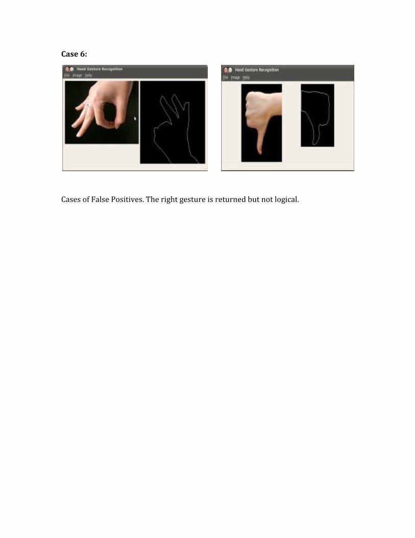
Case 6:
Cases of False Positives. The right gesture is returned but not logical.
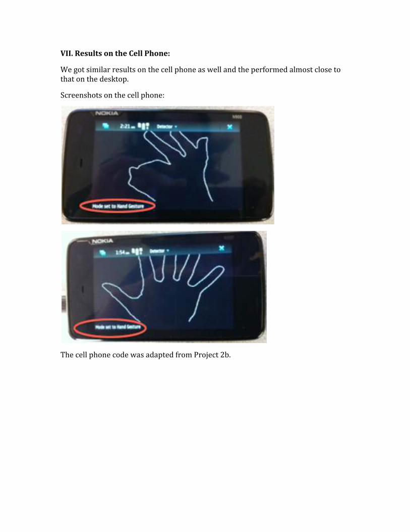
VII. Results on the Cell Phone:
We got similar results on the cell phone as well and the performed almost close to
that on the desktop.
Screenshots on the cell phone:
The cell phone code was adapted from Project 2b.
VIII. Conclusion:
Based on our observation, we can conclude that the results mainly depend on:
1. Threshold, while converting the gray image to the binary image and finding
contours. For example found that uneven lighting across the picture of the hand
caused the algorithm to draw contours around the darkened areas in addition to the
contour around the hand. Changing the threshold prevented that from happening.
2. The threshold for the Ratio test while matching the distance transformed images.
The ratio we used
3. The background, which must preferably be black to get accurate results.
4. An additional check on moments is useful to check if the contours of both the
query image and the candidate image have the same shape.
5. In order to maintain performance the database contains images of small
dimensions.
IX. Program description:
We have adapted our code from the code of Project 2b.
FeaturesUI.cpp: has been customized to get the GUI as shown in the above images.
FeaturesDoc.cpp: contains the actual logic required for this project.
Features.cpp: contains the logic for the cell phone
The main functions in the program are described below.
X. Future Work:
1. Skin segmentation algorithm can be implemented to extract the skin pixels
2. Can have more images of gestures added to the database for the program to
recognize
3. Captions can be added to the gestures recognized
XI. OpenCV Functions used in the program:
1. To compute the distance transform
void cvDistanceTransform( . . . )
2. To find the number of Contours in the image
int cvFindContours( . . . )
2. To compute the moments
double cvMatchShapes ( . . . )
3. To find bounding box’s height, width and center
cvMinAreaRect2( . . .)
4. To find the area of the contour
cvContourArea (…)
XII. Functions implemented by our own:
1. rotate_inverse_warp()
This function extracts the image contained within the bounding box, rotates the image
in the negative direction (the angle is obtained from the bounding box) and creates a
new image.
2. distance transform
This function uses the algorithm described in “Euclidean Distance Transform,” which
replaces binary image pixel intensities with values equal to their Euclidean distance from
the nearest edge. While we implemented this function, we were unable to get it to
work completely, so we ended up using OpenCV’s cvDistTransform().
XIII. Distribution of Work
Work done by Jonathan:
Wrote functions for rotation, scaling, and distance transform. Debugged code, worked
on the report, the presentation slides, and presented the slides during the final
presentation.
Work done by Roopa:
Wrote the main pipeline for the project and also, got the program working on the cell
phone. Debugged code, worked on the report, the presentation slides, and presented
the slides during the final presentation.
XIV: Platform
Ubuntu, OpenCV, C++, Nokia900 (phone device)
XV: Outside Sources
1. The hand gesture images were taken from Google Images.
2. “Distance Transform.” David Coeurjolly.
3. Euclidean Distance Transform, from http://www.cs.auckland.ac.nz/~rklette
4. Learning OpenCV. O'Reilly
5. “Hand Gesture Recognition for Human-Machine Interaction.” Journal of WSCG,
Vol.12, No.1-3, ISSN 1213-6972
Acknowledgements
We’d like to thank Professor Noah Snavely and Kevin Matzen for guiding and assisting us
during this project and the course.
XVI. Program Listing:
All the openCV functions that are used are marked in blue.
/* metric to compute the distance transform */ int found = 0; int dist_type = CV_DIST_L2; int mask_size = CV_DIST_MASK_5; /* This is the main function that computes the matches. The query image //and the database image are pre-processed. Both the images are //converted to binary images and the contours are computed. The openCV //function is used to compute the contours and it also returns the //bounding box information like the height and the width of the //bounding box and also the center of the bounding box with respect to //the image. In addition it also returns the angle of inclination of //the bounding box. This information is used to rotate the binary image //in order to compute the distance transform of the images. The pixel //values of the distance-transformed images are subtracted to compute //the match. If the pixel difference is zero or less than a certain //threshold, then it is determined as a match. The number of such //pixels that satisfy this criterion is counted and the ratio of this //count to the total number of pixels in the image gives us the ratio. //In our program we have set the threshold to be at least 65%. If the //ratio is greater than 65% then the candidate image in consideration //is selected as a match. In addition, the moment value is also //computed and set to between 0.0 and 0.22 to find the best match. */ IplImage* computeMatch(IplImage *src_img, IplImage *cmp_img) { //cvShowImage("src img", src_img); //cvShowImage("cmp_img", cmp_img); //convert the image to gray IplImage* gray_img=0; gray_img = cvCreateImage(cvSize(src_img->width, src_img->height),IPL_DEPTH_8U,1); cvCvtColor ( src_img, gray_img, CV_BGR2GRAY);
dTFvalue.val[0] = distanceFunction2(b, a, dist_origin);
cvSet2D(dist, a, b, dTFvalue); cout << dTFvalue.val[0] << " ";
}
cout << endl; } */ cvConvertScale( dist, dist, 150.0, 0 ); cvPow( dist, dist, 0.5 ); cvConvertScale( dist, dist32s, 1.0, 0.5 ); cvAndS( dist32s, cvScalarAll(255), dist32s, 0 ); cvConvertScale( dist32s, dist8u1, 1, 0 ); return dist8u1; } /* These functions are used in our implementation of the distance transform algorithm. int distanceFunction1(int x, int y, IplImage *Input) {
if(x >= 0 && x < Input->width && y >= 0 && y < Input->height)
{ CvScalar P = cvGet2D(Input, y, x);
if(P.val[0] > 0)
{
return distanceFunction1(x - 1, y, Input) + 1; }
else
{ return 0;
}
} }
int distanceFunction2(int x, int y, IplImage *Input) {
int df1 = distanceFunction1(x, y, Input);
if(df1 != 0)
{ return min(df1, distanceFunction2(x + 1, y, Input) + 1);
}
else {
return 0;
} }*/ /* This function uses the Bounding Box information obtained from the
//contours. The Bounding Box data structure gives us information about //center of the bounding box, the angle of inclination and also the //height and width of the bounding box. // // A new image is created which is nothing but the image contained //within the bounding box. */ IplImage* inverse_warp_rotate(IplImage* before, CvBox2D box) { float pi = 3.141592653; float angle = box.angle * pi/180; //float angle = box.angle; IplImage* after = cvCreateImage(cvSize(box.size.height, box.size.width),before->depth, before->nChannels); /* std::cout << "CLONING COMPLETE: Before " << before->width << " " << before->height << std::endl; std::cout << "CLONING COMPLETE: After " << after->width << " " << after->height << std::endl; std::cout << "Box2D angle " << angle << std::endl; std::cout << "Box2D width " << box.size.width << std::endl; std::cout << "Box2D height " << box.size.height << std::endl; */ // selector chooses between nearest neighbor interpolation (0) or bilinear interpolation (1). //after->width = box.size.width; //after->height = box.size.height; //double b4centerx = ((double)before->width)/2; // double b4centery = ((double)before->height)/2; double aftercenterx = ((double)after->width)/2; double aftercentery = ((double)after->height)/2; // std::cout << "Error between centers: (" << aftercenterx - box.center.x << ", " << aftercentery - box.center.y << ")" << std::endl; for(int a = 0; a < after->width; a++) { for(int b = 0; b < after->height; b++) { // coordinates in downsampled image corresponding to window center in original image double dscoordx = box.center.x;//u/5; //FIXME: don't know what this should be double dscoordy = box.center.y;//v/5; double translatedx = a - aftercenterx; double translatedy = b - aftercentery; double rotatedx = translatedx * cos(angle) + translatedy * (sin(angle)); double rotatedy = translatedx * (-sin(angle)) + translatedy * cos(angle); double transbackx = rotatedx + dscoordx; double transbacky = rotatedy + dscoordy;
// P, Q, R, S coordinates where P, Q, R, S are the nearest neighboring pixels std::vector<int>Nx; std::vector<int>Ny; int Px = floor(transbackx); Nx.push_back(Px); int Py = floor(transbacky); Ny.push_back(Py); int Qx = floor(transbackx)+1; Nx.push_back(Qx); int Qy = floor(transbacky); Ny.push_back(Qy); int Rx = floor(transbackx); Nx.push_back(Rx); int Ry = floor(transbacky)+1; Ny.push_back(Ry); int Sx = floor(transbackx)+1; Nx.push_back(Sx); int Sy = floor(transbacky)+1; Ny.push_back(Sy); for(int o = 0; o < Nx.size(); o++) { if(Nx[o] < 0) { Nx[o] = 0; } else if(Nx[o] >= before->width) { Nx[o] = before->width-1; } if(Ny[o] < 0) { Ny[o] = 0; } else if(Ny[o] >= before->height) { Ny[o] = before->height-1; } } double alpha = transbackx - Nx[0]; double beta = transbacky - Ny[0]; CvScalar P = cvGet2D(before, Ny[0], Nx[0]); CvScalar Q = cvGet2D(before, Ny[1], Nx[1]); CvScalar R = cvGet2D(before, Ny[2], Nx[2]); CvScalar S = cvGet2D(before, Ny[3], Nx[3]); CvScalar MOPSpixel = cvGet2D(before, Ny[3], Nx[3]); MOPSpixel.val[0] = (1-alpha)*(1-beta)*P.val[0] + alpha*(1-beta)*Q.val[0] + (1-alpha)*beta*R.val[0] + alpha*beta*S.val[0]; cvSet2D(after, b, a, MOPSpixel); } }
// apply threshold: those pixels that have intensities > 0 will have them set to 1. for(int a = 0; a < after->height; a++) { for(int b = 0; b < after->width; b++) { CvScalar Afterpixel = cvGet2D(after, a, b); Afterpixel.val[0] = (Afterpixel.val[0] > 0 ? 255 : 0); cvSet2D(after, a, b, Afterpixel); } } //std::cout << "DOWN WITH ROTATING" << std::endl; return after; } /* This function converts a 1-channel image to a 3-channel image */