Rev – 11/14 Page 1 of 11
-- CSGP-1 -- (CEILING SUSPENDED GOAL POST)
Installation Instructions
Call Jaypro Sports Equipment at 1-800-243-0533
during regular business hours for technical support.
www.jaypro.com
Rev – 11/14 Page 2 of 11
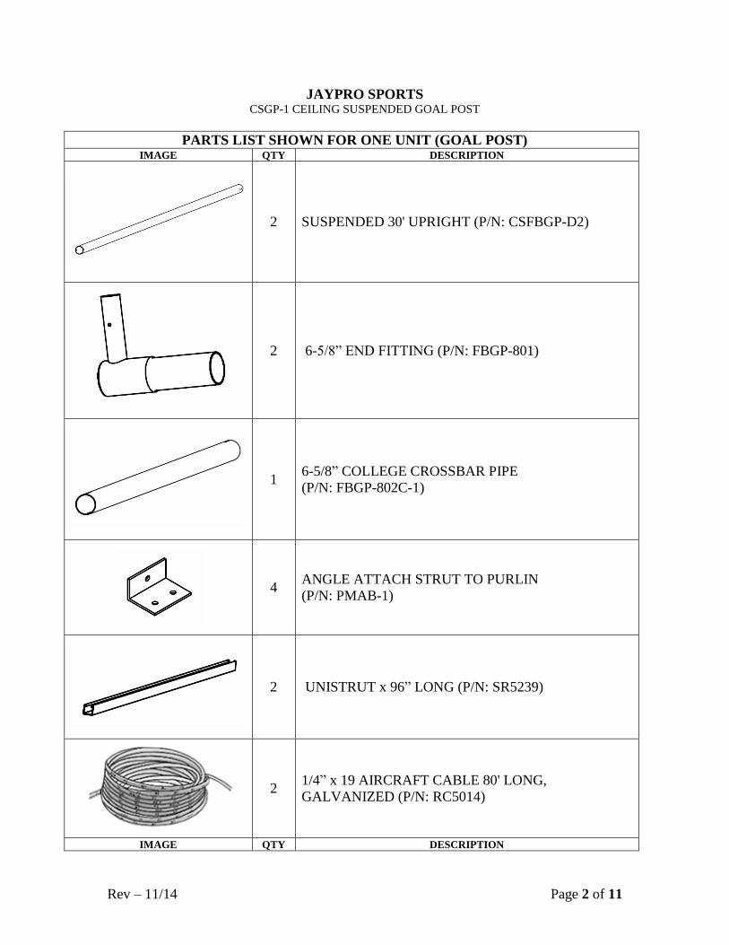
JAYPRO SPORTS CSGP-1 CEILING SUSPENDED GOAL POST
PARTS LIST SHOWN FOR ONE UNIT (GOAL POST)
IMAGE QTY DESCRIPTION
2 SUSPENDED 30' UPRIGHT (P/N: CSFBGP-D2)
2 6-5/8” END FITTING (P/N: FBGP-801)
1 6-5/8” COLLEGE CROSSBAR PIPE
(P/N: FBGP-802C-1)
4 ANGLE ATTACH STRUT TO PURLIN
(P/N: PMAB-1)
2 UNISTRUT x 96” LONG (P/N: SR5239)
2 1/4” x 19 AIRCRAFT CABLE 80' LONG,
GALVANIZED (P/N: RC5014)
IMAGE QTY DESCRIPTION
Rev – 11/14 Page 3 of 11
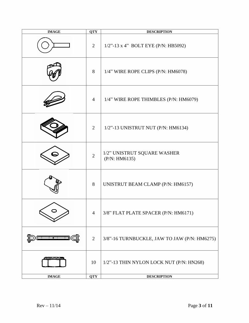
IMAGE QTY DESCRIPTION
2 1/2”-13 x 4” BOLT EYE (P/N: HB5092)
8 1/4” WIRE ROPE CLIPS (P/N: HM6078)
4 1/4” WIRE ROPE THIMBLES (P/N: HM6079)
2 1/2”-13 UNISTRUT NUT (P/N: HM6134)
2 1/2” UNISTRUT SQUARE WASHER
(P/N: HM6135)
8 UNISTRUT BEAM CLAMP (P/N: HM6157)
4 3/8” FLAT PLATE SPACER (P/N: HM6171)
2 3/8”-16 TURNBUCKLE, JAW TO JAW (P/N: HM6275)
10 1/2”-13 THIN NYLON LOCK NUT (P/N: HN268)
IMAGE QTY DESCRIPTION
Rev – 11/14 Page 4 of 11
IMAGE QTY DESCRIPTION
2 1/2”-13 FLANGE LOCK NUT (P/N: HN5038)
12 3/8”-16 FLANGE HEX NUT (P/N: HN5042)
8 3/8”-16 x 1” HEX BOLT (P/N: HS286)
4 3/8”-16 x 3” HEX HEAD CAP SCREW (P/N: HS292)
6 1/2” - 13 x 5” HEX HEAD SCREW (P/N: HS5042)
4 1/2” - 13 x 8” HEX HEAD SCREW (P/N: HS5066)
10 1/2” FLAT WASHER (P/N: HW2044)
12 3/8” FLAT WASHER (P/N: HW2050)
IMAGE QTY DESCRIPTION
Rev – 11/14 Page 5 of 11
IMPORTANT NOTICE:
1) BEFORE EACH USE CHECK EQUIPMENT FOR PROPER CONNECTING
HARDWARE AND STRUCTURAL INTEGRITY. REPLACE DAMAGED OR
MISSING HARDWARE IMMEDIATELY.
2) USE OF THIS EQUIPMENT OTHER THAN INTENDED, MAY BE
HAZARDOUS.
3) ALTERATION OR MODIFICATION OF THIS EQUIPMENT MAY BE
HAZARDOUS AND RESULT IN INJURY. FOR REPAIR OR
REPLACEMENT, CONTACT YOUR DEALER OR JAYPRO SPORTS.
ASSEMBLY INSTRUCTIONS
TOOLS REQUIRED:
(1) 9/16” Socket Wrench and Box Wrench
(1) 3/4” Socket Wrench and Box Wrench
(1) 15/16” Socket Wrench and Box Wrench
(1) Scaffolding, Lull or Boom Lift
(1) Electric Drill
(1) Drill Bits:
a. 1/2"
b. 3/16” & 3/8” drill bits to pilot holes (recommended)
(1) 17/32” Transfer Punch (recommended)
(1) 3’ Level Device
Important Note:
Installation of the ceiling suspended goal post system requires the lifting and
handling of substantial weight, up to 340 lbs. Safe installation requires at least four men
and the use of appropriate material handling equipment such as scaffolding, a Lull or
boom lift.
The ceiling suspended goal post offers the ability to adjust the height of the
crossbar and plumb it independently. Care should be taken at each step to ensure the
framework is square and plumb.
Rev – 11/14 Page 6 of 11
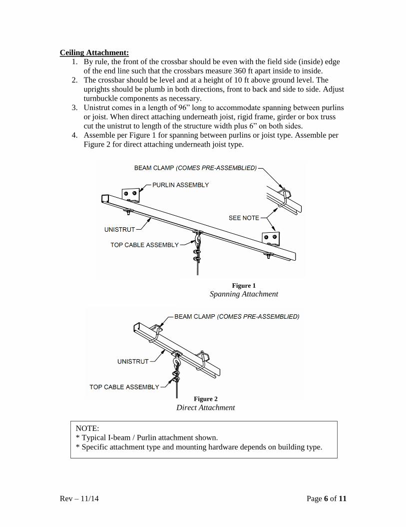
Ceiling Attachment:
1. By rule, the front of the crossbar should be even with the field side (inside) edge
of the end line such that the crossbars measure 360 ft apart inside to inside.
2. The crossbar should be level and at a height of 10 ft above ground level. The
uprights should be plumb in both directions, front to back and side to side. Adjust
turnbuckle components as necessary.
3. Unistrut comes in a length of 96” long to accommodate spanning between purlins
or joist. When direct attaching underneath joist, rigid frame, girder or box truss
cut the unistrut to length of the structure width plus 6” on both sides.
4. Assemble per Figure 1 for spanning between purlins or joist type. Assemble per
Figure 2 for direct attaching underneath joist type.
Figure 2
Direct Attachment
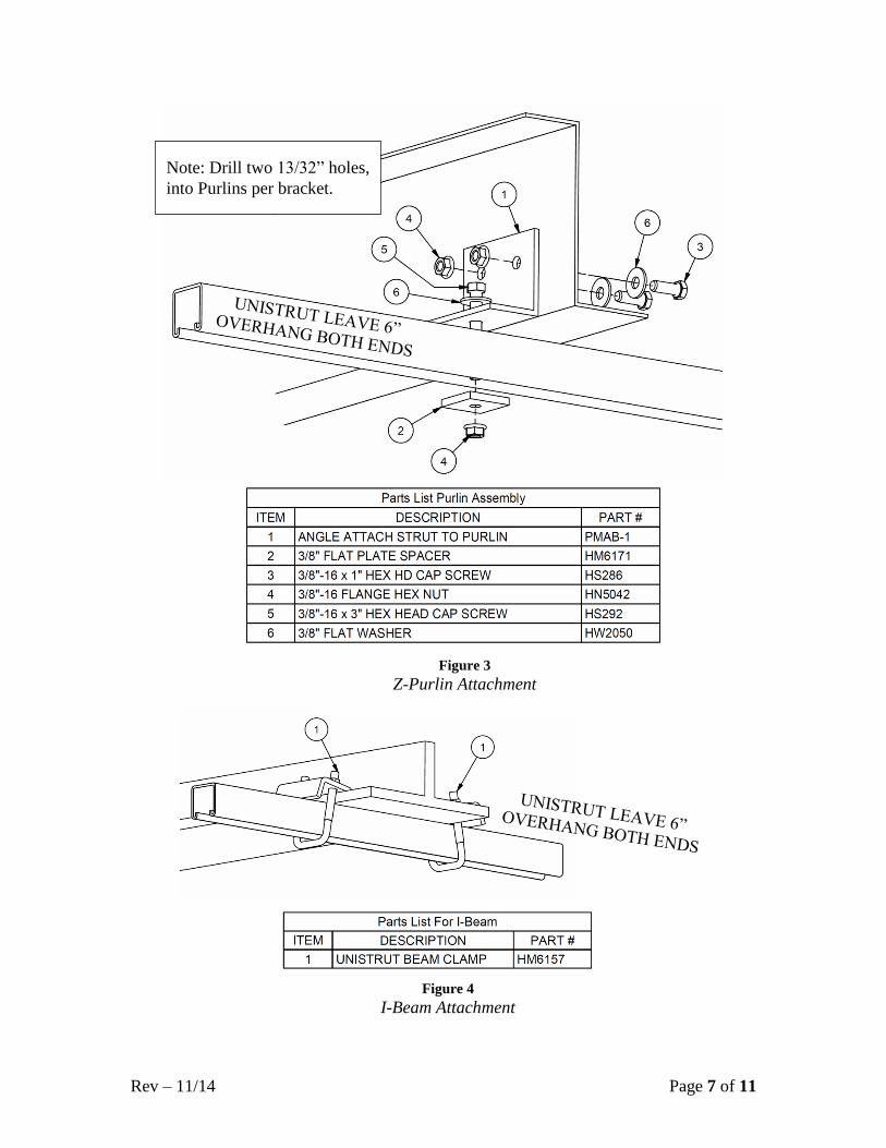
NOTE:
* Typical I-beam / Purlin attachment shown.
* Specific attachment type and mounting hardware depends on building type.
Figure 1
Spanning Attachment
Rev – 11/14 Page 7 of 11
Figure 4
I-Beam Attachment
Note: Drill two 13/32” holes,
into Purlins per bracket.
Figure 3
Z-Purlin Attachment
Rev – 11/14 Page 8 of 11
Suspended Cable:
1. Install the eyebolts on the support structure as shown.
2. Make up one end of each of the two cables, see Figure 5. Tighten the cable
clamps using a 7/16” nut driver.
3. Estimate the approximate length of cable by measuring the height of the eyebolt
and subtracting about 41 ft.
4. Make up the other end of each cable, leaving the clamps hand tight with excess
cable left until the final length is established.
2” TYPICAL SPACING
BETWEEN CLAMPS
Figure 5
BOTTOM VIEW SHOWN
CORRECT WAY TO
INSTALL CABLE CLAMPS,
ORIENT THE SADDLE ON
THE CONTINUOUS
CABLE LENGTH SIDE.
Rev – 11/14 Page 9 of 11
Figure 6
Rev – 11/14 Page 10 of 11
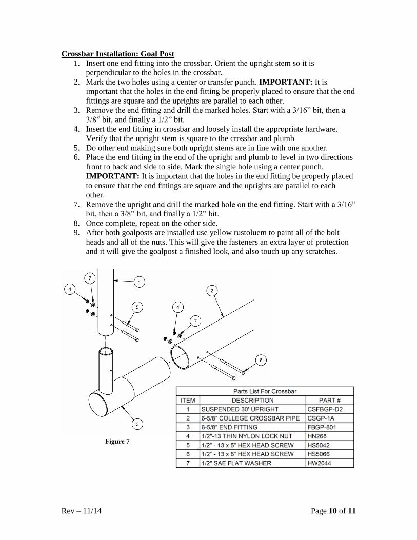
Crossbar Installation: Goal Post
1. Insert one end fitting into the crossbar. Orient the upright stem so it is
perpendicular to the holes in the crossbar.
2. Mark the two holes using a center or transfer punch. IMPORTANT: It is
important that the holes in the end fitting be properly placed to ensure that the end
fittings are square and the uprights are parallel to each other.
3. Remove the end fitting and drill the marked holes. Start with a 3/16” bit, then a
3/8” bit, and finally a 1/2” bit.
4. Insert the end fitting in crossbar and loosely install the appropriate hardware.
Verify that the upright stem is square to the crossbar and plumb
5. Do other end making sure both upright stems are in line with one another.
6. Place the end fitting in the end of the upright and plumb to level in two directions
front to back and side to side. Mark the single hole using a center punch.
IMPORTANT: It is important that the holes in the end fitting be properly placed
to ensure that the end fittings are square and the uprights are parallel to each
other.
7. Remove the upright and drill the marked hole on the end fitting. Start with a 3/16”
bit, then a 3/8” bit, and finally a 1/2” bit.
8. Once complete, repeat on the other side.
9. After both goalposts are installed use yellow rustoluem to paint all of the bolt
heads and all of the nuts. This will give the fasteners an extra layer of protection
and it will give the goalpost a finished look, and also touch up any scratches.
Figure 7
Rev – 11/14 Page 11 of 11
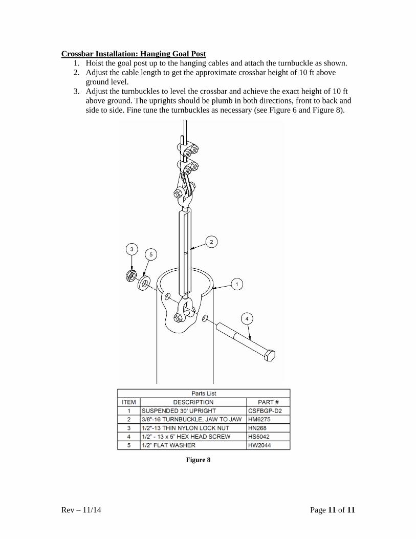
Crossbar Installation: Hanging Goal Post
1. Hoist the goal post up to the hanging cables and attach the turnbuckle as shown.
2. Adjust the cable length to get the approximate crossbar height of 10 ft above
ground level.
3. Adjust the turnbuckles to level the crossbar and achieve the exact height of 10 ft
above ground. The uprights should be plumb in both directions, front to back and
side to side. Fine tune the turnbuckles as necessary (see Figure 6 and Figure 8).
Figure 8