+ All Categories

CSNP661

Date post: 24-Oct-2014
Category:
Upload: long-nguyen
View: 13 times
Download: 2 times
Share this document with a friend
9
Solid State Sensors CSN Series Closed Loop Current Sensors 60 Honeywell 1 MICRO SWITCH Sensing and Control 1 1-800-537-6945 USA 1F1-815-235-6847 International 1 1-800-737-3360 Canada FEATURES 1 Current sensing up to 1200 amps 1 Measures AC, DC and impulse currents 1 Lowest cost/performance ratio 1 Rapid response, no overshoot 1 High overload capacity 1 High level of electrical isolation between primary and secondary circuits 1 Small size and weight CLOSED LOOP SENSORS Closed loop current sensors measure AC, DC and impulse currents over 0-25, 0-50, 0-100, 0-600 and 0-1200 Amp rang- es. The CSN Series is based on the princi- ples of the Hall effect and the null balance or zero magnetic flux method (feedback system). The magnetic flux in the sensor core is constantly controlled at zero. The amount of current required to balance zero flux is the measure of the primary current flowing through the conductor, multiplied by the ratio of the primary to secondary windings. This closed loop current is the output from the device and presents an image of the primary current reduced by the number of secondary turns at any time. This current can be expressed as a voltage by passing it through a resistor. CATALOG NUMBER SYSTEM PLEASE NOTE: This matrix is intended only to aid you in identifying sensor cata- log listings. It is not all-inclusive, and must not be used to form new listings. Example: CSNA111 CSN Closed Loop Current Sensor Current Range (Peak/RMS nom.) A ±70 A/50 A rms nom. B ±100 A/50 A rms nom. C ±90 A/50 A rms nom. D ±22 A/15 A rms nom. E ±36 A/25 A rms nom. F ±150 A/100 A rms nom. J ±600 A/300 A rms nom. K ±1200 A/500 A rms nom. L ±600 A/300 A rms nom. M ±1200 A/500 A rms nom. P ±90 A/50 A rms nom. R ±200 A/125 A rms nom. T ±150 A/50 A rms nom. Supply Voltage 1 ±15 V 2 ±13 V 3 ±5V 4 ±12 V to 18 V 5 ±15 V to 24 V 6 ±12 V to 15 V Coil Characteristics 1 1:1000 turns/90 V @ 70°C 2 1:2000 turns/160 V @ 70°C 3 1:2000 turns/130 V @ 70°C 4 1:1000 turns/50 V @ 70°C 5 1:1000 turns/110 V @ 70°C 6 1:1000 turns/30 V @ 70°C 7 1:2000 turns/80 V @ 70°C 8 1:2000 turns/25 V @ 70°C 9 1:5000 turns/50 V @ 85°C Housing Material 1 Polycarbonate/ABS blend
Transcript

Solid State Sensors CSN SeriesClosed Loop Current Sensors

60 Honeywell 1 MICRO SWITCH Sensing and Control 1 1-800-537-6945 USA 1 F1-815-235-6847 International 1 1-800-737-3360 Canada

FEATURES1 Current sensing up to 1200 amps1 Measures AC, DC and impulse

currents1 Lowest cost/performance ratio1 Rapid response, no overshoot1 High overload capacity1 High level of electrical isolation

between primary and secondarycircuits

1 Small size and weight

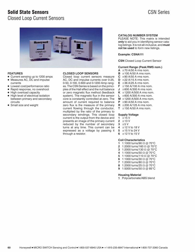
CLOSED LOOP SENSORSClosed loop current sensors measureAC, DC and impulse currents over 0-25,0-50, 0-100, 0-600 and 0-1200 Amp rang-es. The CSN Series is based on the princi-ples of the Hall effect and the null balanceor zero magnetic flux method (feedbacksystem). The magnetic flux in the sensorcore is constantly controlled at zero. Theamount of current required to balancezero flux is the measure of the primarycurrent flowing through the conductor,multiplied by the ratio of the primary tosecondary windings. This closed loopcurrent is the output from the device andpresents an image of the primary currentreduced by the number of secondaryturns at any time. This current can beexpressed as a voltage by passing itthrough a resistor.

CATALOG NUMBER SYSTEMPLEASE NOTE: This matrix is intendedonly to aid you in identifying sensor cata-log listings. It is not all-inclusive, and mustnot be used to form new listings.

Example: CSNA111

CSN Closed Loop Current Sensor

Current Range (Peak/RMS nom.)A ±70 A/50 A rms nom.B ±100 A/50 A rms nom.C ±90 A/50 A rms nom.D ±22 A/15 A rms nom.E ±36 A/25 A rms nom.F ±150 A/100 A rms nom.J ±600 A/300 A rms nom.K ±1200 A/500 A rms nom.L ±600 A/300 A rms nom.M ±1200 A/500 A rms nom.P ±90 A/50 A rms nom.R ±200 A/125 A rms nom.T ±150 A/50 A rms nom.

Supply Voltage1 ±15 V2 ±13 V3 ±5 V4 ±12 V to 18 V5 ±15 V to 24 V6 ±12 V to 15 V

Coil Characteristics1 1:1000 turns/90 V @ 70°C2 1:2000 turns/160 V @ 70°C3 1:2000 turns/130 V @ 70°C4 1:1000 turns/50 V @ 70°C5 1:1000 turns/110 V @ 70°C6 1:1000 turns/30 V @ 70°C7 1:2000 turns/80 V @ 70°C8 1:2000 turns/25 V @ 70°C9 1:5000 turns/50 V @ 85°C

Housing Material1 Polycarbonate/ABS blendPDFINFO p a g e - 0 6 0

Solid State Sensors CSN SeriesClosed Loop Current Sensors

Honeywell 1 MICRO SWITCH Sensing and Control 1 1-800-537-6945 USA 1 F1-815-235-6847 International 1 1-800-737-3360 Canada 61

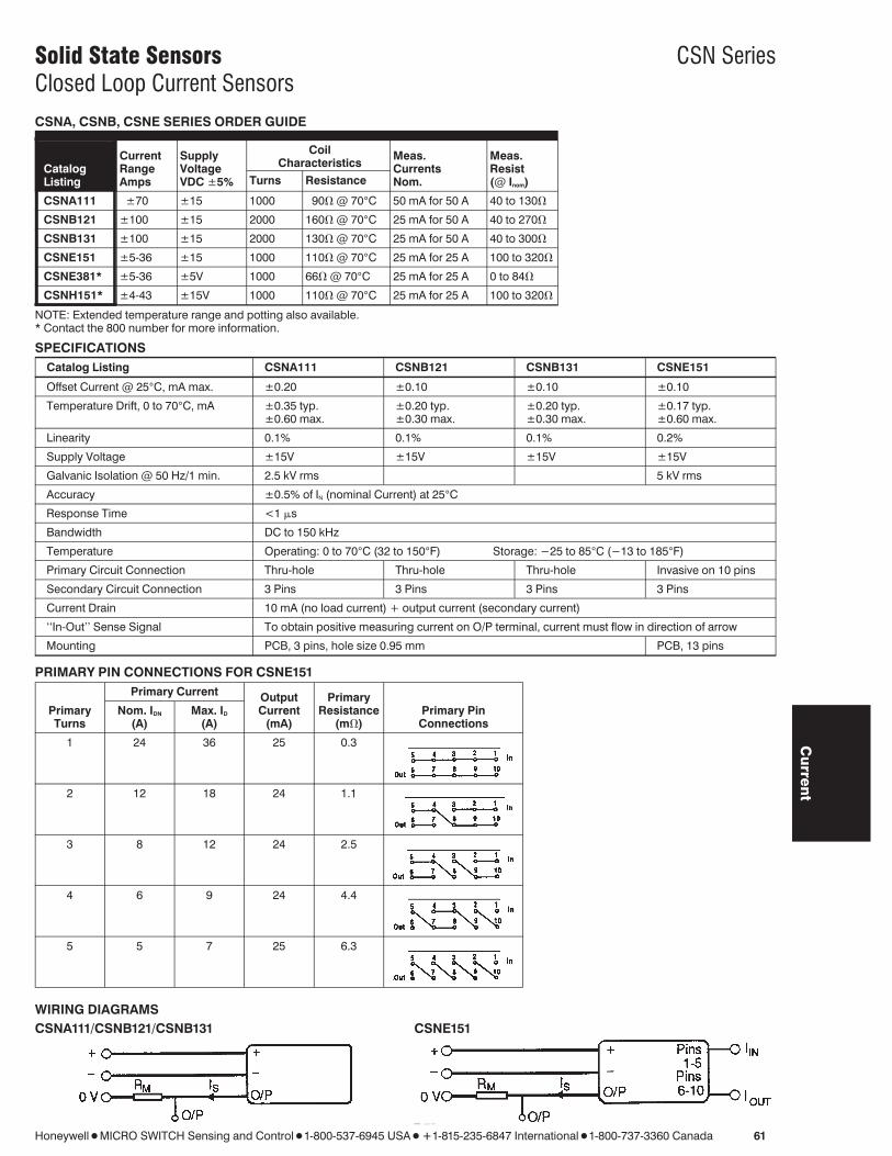
CSNA, CSNB, CSNE SERIES ORDER GUIDE

CatalogListing

CurrentRangeAmps

SupplyVoltageVDC ±5%

CoilCharacteristics

Turns Resistance

Meas.CurrentsNom.

Meas.Resist(@ Inom)

CSNA111 ±70 ±15 1000 90V @ 70°C 50 mA for 50 A 40 to 130V

CSNB121 ±100 ±15 2000 160V @ 70°C 25 mA for 50 A 40 to 270V

CSNB131 ±100 ±15 2000 130V @ 70°C 25 mA for 50 A 40 to 300V

CSNE151 ±5-36 ±15 1000 110V @ 70°C 25 mA for 25 A 100 to 320V

CSNE381* ±5-36 ±5V 1000 66V @ 70°C 25 mA for 25 A 0 to 84V

CSNH151* ±4-43 ±15V 1000 110V @ 70°C 25 mA for 25 A 100 to 320V

NOTE: Extended temperature range and potting also available.* Contact the 800 number for more information.

SPECIFICATIONSCatalog Listing CSNA111 CSNB121 CSNB131 CSNE151

Offset Current @ 25°C, mA max. ±0.20 ±0.10 ±0.10 ±0.10

Temperature Drift, 0 to 70°C, mA ±0.35 typ. ±0.20 typ. ±0.20 typ. ±0.17 typ.±0.60 max. ±0.30 max. ±0.30 max. ±0.60 max.

Linearity 0.1% 0.1% 0.1% 0.2%

Supply Voltage ±15V ±15V ±15V ±15V

Galvanic Isolation @ 50 Hz/1 min. 2.5 kV rms 5 kV rms

Accuracy ±0.5% of IN (nominal Current) at 25°CResponse Time <1 ms

Bandwidth DC to 150 kHz

Temperature Operating: 0 to 70°C (32 to 150°F) Storage: −25 to 85°C (−13 to 185°F)

Primary Circuit Connection Thru-hole Thru-hole Thru-hole Invasive on 10 pins

Secondary Circuit Connection 3 Pins 3 Pins 3 Pins 3 Pins

Current Drain 10 mA (no load current) + output current (secondary current)

‘‘In-Out’’ Sense Signal To obtain positive measuring current on O/P terminal, current must flow in direction of arrow

Mounting PCB, 3 pins, hole size 0.95 mm PCB, 13 pins

PRIMARY PIN CONNECTIONS FOR CSNE151Primary Current

PrimaryTurns

Nom. IDN

(A)Max. ID

(A)

OutputCurrent

(mA)

PrimaryResistance

(mV)Primary PinConnections

1 24 36 25 0.3

2 12 18 24 1.1

3 8 12 24 2.5

4 6 9 24 4.4

5 5 7 25 6.3

WIRING DIAGRAMSCSNA111/CSNB121/CSNB131 CSNE151

PDFINFO p a g e - 0 6 1

Cu

rrent

Solid State Sensors CSN SeriesClosed Loop Current Sensors

62 Honeywell 1 MICRO SWITCH Sensing and Control 1 1-800-537-6945 USA 1 F1-815-235-6847 International 1 1-800-737-3360 Canada

MOUNTING DIMENSIONS (for reference only)

CSNA111, CSNB121, CSNB131

CSNE151/CSNE381

CSNH151

PDFINFO p a g e - 0 6 2

Solid State Sensors CSN SeriesClosed Loop Current Sensors

Honeywell 1 MICRO SWITCH Sensing and Control 1 1-800-537-6945 USA 1 F1-815-235-6847 International 1 1-800-737-3360 Canada 63

CSNJ, CSNK SERIES ORDER GUIDE

Catalog Listings

CurrentRangeAmps

SupplyVoltage

VDC ± 5%

Coil Characteristics Meas.Currents

Nom.Meas.

Resist (@ Inom)Turns Resistance

CSNJ481 ±600 ±12 to 18 2000 25V @ 70°C 150 mA for 300 A 0 to 70V

CSNJ481-001* ±600 ±12 to 18 2000 25V @ 70°C 150 mA for 300 A 0 to 70V

CSNJ481-002 ±600 ±12 to 18 2000 25V @ 70°C 150 mA for 300 A 0 to 70V

CSNJ481-003* ±600 ±12 to 18 2000 25V @ 70°C 150 mA for 300 A 0 to 70V

CSNK591 ±1200 ±15 to 24 5000 50V @ 70°C 100 mA for 500 A 0 to 130V

CSNK591-001* ±1200 ±15 to 24 5000 50V @ 70°C 100 mA for 500 A 0 to 130V

CSNK591-002 ±1200 ±15 to 24 5000 50V @ 70°C 100 mA for 500 A 0 to 130V

CSNK591-003* ±1200 ±15 to 24 5000 50V @ 70°C 100 mA for 500 A 0 to 130V

*Fitted with busbar

SPECIFICATIONS

Catalog Listings CSNJ481 CSNJ481-002 CSNK591 CSNK591-002CSNJ481-001 CSNJ481-003 CSNK591-001 CSNK591-003

Offset Current @ 25°C, mA max. ±0.30 ±0.30 ±0.20 ±0.20

Temperature Drift, 0 to 70°C, mA ±0.30 typ. ±0.30 typ. ±0.20 typ. ±0.20 typ.±0.50 max. ±0.50 max. ±0.30 max. ±0.30 max.

Linearity ±0.1% ±0.1% ±0.1% ±0.1%

Supply Voltage ±12 to ±18V ±12 to ±18V ±15 to ±24V ±15 to ±24V

Galvanic Isolation @ 50 Hz/1 min. 7.5 kV rms 7.5 kV rms 6 kV rms 6 kV rms

Accuracy ±0.5% of IN (nominal Current) at 25°CResponse Time <1 ms

Bandwidth DC to 150 kHz

Operating Temperature −40 to 85°C 0 to 70°C −40 to 85°C 0 to 70°C(−40 to 185°F) (32 to 158°F (−40 to 185°F) (32 to 158°F)

Storage Temperature −40 to 90°C −25 to 85°C −40 to 90°C −25 to 85°C(−40 to 194°F) (−13 to 85°F (−40 to 194°F) (−13 to 85°F)

Primary Circuit Connection Thru-hole or busbar Thru-hole or busbar Thru-hole or busbar Thru-hole or busbar

Secondary Circuit Connection 3 pins 3 pins 3 pins 3 pins

Current Drain 14 mA (no load current) + output current 22 mA (24 V) + output current

‘‘In-Out’’ Sense Signal To obtain positive measuring current on O/P terminal, current must flow in direction of arrow

Mounting Faston, 3 pins Push-on (spade), 3 terminals

WIRING DIAGRAM

PDFINFO p a g e - 0 6 3

Cu

rrent

Solid State Sensors CSN SeriesClosed Loop Current Sensors

64 Honeywell 1 MICRO SWITCH Sensing and Control 1 1-800-537-6945 USA 1 F1-815-235-6847 International 1 1-800-737-3360 Canada

MOUNTING DIMENSIONS (for reference only)

CSNJ481

CSNK591

PDFINFO p a g e - 0 6 4

Solid State Sensors CSN SeriesClosed Loop Current Sensors

Honeywell 1 MICRO SWITCH Sensing and Control 1 1-800-537-6945 USA 1 F1-815-235-6847 International 1 1-800-737-3360 Canada 65

CSNL, CSNM SERIES ORDER GUIDE

Catalog Listings

PeakCurrent

Range Amps

SupplyVoltage

VDC ± 5%

Coil Characteristics Meas.Currents

Nom.Meas.

Resist (@ Inom)Turns Resistance

CSNL181 ±600 ±12 to 18 2000 25V @ 70°C 150 mA for 300 A 0 to 70V

CSNM191 ±1000 ±12 to 18 5000 50V @ 70°C 100 mA for 500 A 0 to 120V

SPECIFICATIONS

Catalog Listings CSNL181 CSNM191

Offset Current @ 25°C, mA max. ±0.30 ±0.20

Temperature Drift, 0 to 70°C, mA ±0.30 typ. ±0.20 typ.±0.50 max. ±0.30 max.

Linearity ±0.1% ±0.1%

Supply Voltage ±12 to ±18V ±12 to ±18V

Galvanic Isolation @ 50 Hz/1 min. 7.5 kV rms 7.5 kV rms

Accuracy ±0.5% of IN (nominal Current) at 25°CResponse Time 500 ns <1 ms

Bandwidth DC to 150 kHz

Operating Temperature −40 to 85°C (−40 to 185°F)

Storage Temperature −40 to 90°C (−40 to 194°F)

Primary Circuit Connection Thru-hole Thru-hole

Secondary Circuit Connection 3 pins 3 pins

Current Drain 14 mA (no load current) + output current

‘‘In-Out’’ Sense Signal To obtain positive measuring current on O/P terminal, current must flowin direction of arrow

Mounting Faston, 3 pins

WIRING DIAGRAM

PDFINFO p a g e - 0 6 5

Cu

rrent

Solid State Sensors CSN SeriesClosed Loop Current Sensors

66 Honeywell 1 MICRO SWITCH Sensing and Control 1 1-800-537-6945 USA 1 F1-815-235-6847 International 1 1-800-737-3360 Canada

MOUNTING DIMENSIONS (for reference only)

CSNL181

CSNM191

PDFINFO p a g e - 0 6 6

Solid State Sensors CSN SeriesClosed Loop Current Sensors

Honeywell 1 MICRO SWITCH Sensing and Control 1 1-800-537-6945 USA 1 F1-815-235-6847 International 1 1-800-737-3360 Canada 67

CSNF, CSNR, CSNP, CSNT SERIES ORDER GUIDE

Catalog Listings

PeakCurrent

Range Amps

SupplyVoltage

VDC ± 5%

Coil Characteristics Meas.Currents

Nom.Meas.

Resist (@ Inom)Turns Resistance

CSNP661 ±90 ±12 to 15 1000 30V @ 70°C 50 mA for 50 A 50 to 100V

CSNT651 ±150 ±12 to 15 2000 100V @ 70°C 25 mA for 50 A 40 to 75V

CSNF161 ±150 ±12 to 15 1000 30V @ 70°C 100 mA for 100 A 10 to 40V

CSNF151 ±180 ±12 to 15 2000 100V @ 70°C 50 mA for 100 A 10 to 75V

CSNR161 ±200 ±12 to 15 1000 30V @ 70°C 125 mA for 125 A 30 to 40V

CSNR151 ±200 ±12 to 15 2000 100V @ 70°C 62.5 mA for 125 A 10 to 40V

NOTE: Busbar options available.

SPECIFICATIONS

Catalog Listings CSNP661 CSNT651 CSNF161 CSNF151 CSNR161 CSNR151

Offset Current @ 25°C, mA max. ±0.20 ±0.10 ±0.20 ±0.10 ±0.20 ±0.10

Temperature Drift, 0 to 70°C, mA ±0.30 typ. ±0.15 typ. ±0.30 typ. ±0.15 typ. ±0.30 typ. ±0.15 typ.±0.50 max. ±0.25 max. ±0.50 max. ±0.25 max. ±0.60 max. ±0.30 max.

Linearity ±0.1% ±0.1% ±0.1% ±0.1% ±0.1% ±0.1%

Supply Voltage ±12 to 15V ±12 to 15V ±12 to 15V ±12 to 15V ±12 to 15V ±12 to 15V

Galvanic Isolation @ 50 Hz/1 min. 3 kV rms 3 kV rms 3 kV rms 3 kV rms 3 kV rms 3 kV rms

Accuracy ±0.5% of IN (nominal Current) at 25°CResponse Time <500 ns

Bandwidth DC to 150 kHz

Operating Temperature −40 to 85°C (−40 to 185°F) −40 to 85°C (−40 to 185°F)

Storage Temperature −40 to 90°C (−40 to 194°F) −40 to 90°C (−40 to 194°F)

Primary Circuit Connection Thru-hole

Secondary Circuit Connection 3 pins

Current Drain 10 mA (no load current) +output current 14 mA (no load current) + output current

‘‘In-Out’’ Sense Signal To obtain positive measuring current on O/P terminal, current must flow in direction of arrow

Mounting 3 pins

Pin Style A A B B B B

WIRING DIAGRAM

PDFINFO p a g e - 0 6 7

Cu

rrent

Solid State Sensors CSN SeriesClosed Loop Current Sensors

68 Honeywell 1 MICRO SWITCH Sensing and Control 1 1-800-537-6945 USA 1 F1-815-235-6847 International 1 1-800-737-3360 Canada

MOUNTING DIMENSIONS (for reference only)

PDFINFO p a g e - 0 6 8


Recommended