17
N.Z. TECHNICAL INFORMATION GUIDE Cultured Stone ®
| Date post: | 06-Mar-2018 |
| Category: |
Documents |
| Upload: | duonghuong |
| View: | 215 times |
| Download: | 2 times |
N.Z. techNical iNformatioN guide
Cultured Stone®

2 3NZ BRICK AND STONE | TECHNICAL INFORMATIONNZ BRICK AND STONE | TECHNICAL INFORMATION
Cultured Stone®Cultured Stone®
IntroductionContents
Cultured Stone® Installation Guide can also be found
at www.midlandbrick.co.nz
Building code requirements may vary from area to area. Check
with local authorities for building code requirements in your
area. Carefully read all information contained in the technical
installation guide before proceeding with your Cultured Stone®
cladding application. Observe safety precautions. Cultured Stone®
products are covered by a 50-Year Warranty.
Please refer to the full Warranty available at the time of supply.
ImportantNZ Brick & Stone accepts no responsibility or liability for the
contents of the guide (including any printing or typographical
errors) and recommends that all standards, specifications and
recommendations be independently checked.
It is to be understood that the requirements and methods detailed
in this guide are current at the time of printing. However, they may
be modified or completely changed to suit improved techniques or
new designs in the future.
Please note: This Australian brochure has been amended to
suit the New Zealand market, where practical to do so.
Dressed Fieldstone in Chardonnay
Phot
ogra
pher
: Mat
thew
Mal
lett
Brick, Block and Concrete Substrates 20-23
Fig 17: Brick or Block Work Typical Construction 20
Fig 18: Brick or Block Work Veneer - Plan 20
Fig 19: Brick or Block Work Veneer - Section 21
Fig 20: Plastered Internal Masonary Wall - Section 21
Fig 21: Brick or Block Base - Section 22
Fig 22: Concrete Tilt Up or Pre-Cast Panel - Section 23
Fig 23: Concrete Tilt Up or Pre-Cast Panel - Plan 23
Cladding Transitions & Window Junctions 24-26
Fig 24: Sill Render Transition - Section 24
Fig 25: Sill Cladding Transition - Section 24
Fig 26: Sill at Window - Section 25
Fig 27: Typical Window Sill - Section 25
Fig 28: Typical Window Head - Section 26
Fig 29: Sill at Window - Section 26
Fascias and Eaves 27-28
Fig 30: Typical Raking Fascia - Section 27
Fig 31: Typical Raking Eave - Section 27
Fig 32: Typical Flush Fascia - Section 28
Fig 33: Typical Eave - Section 28
Cappings 29-30
Fig 34: Retaining Wall - Section 29
Fig 35: Brick or Block Work Parapet - Section 30
Fig 36: Brick or Block Work Parapet Flashing Capping- Section 30
Test Results 31
Contacts and Further Information 32
Introduction 3
Estimating Stone Required 4
How to Estimate Total Stone Required 4
Estimating Details 4
Materials and Tools Required 5
Mortar Components 5
Water Resistive Barrier (WRB) 5
Flashing 5
Expanded Metal Mesh 5
Fasteners 5
Masonry Sealer 5
Tools 5
Typical Installations 6
Timber Frame 6
Brick or Block Work 6
Tilt or Pre-Cast Panel 6
Float and Set 6
Surface Preparation 7
Timber Frame 7
Brick or Block Work 7
Tilt or Pre-Cast Panel 8
Plastered Finish 8
Water Resistive Barrier (WRB) 9
Expanded Metal Mesh Preparation 9
Caution 9
Primer and Mortar Mix 10
Primer 10
Mortar 10
Application 11
Prepare Your Work Area 11
Applying Cultured Stone® Cladding 11-12
Grouting and Finishing Joints 12
Surface Cleaning 12
Sill Installations 13
Water Features 13
Exterior Application Notes 13
Installation Over Foam 13
Capping Off Exposed Top of Exterior Walls 13
Retaining Walls 13
Chimney Cap 13
Additional Instructions 14For: Pro-Fit™ Ledgestone, Pro-Fit™ Alpine Ledgestone
and European Castle Stone
Fitting the Joints 14
Starting Point 14
Install Corner Pieces First 14
Setting the Stone Cladding 14
Install Flat Pieces 14
Cutting and Trimming 14
Finishing Joints 14
Surface Cleaning 14
Internal Installations 14
General Information 15
Cleaning 15
Salt and De-Icing Chemicals 15
Scuffing 15
Efflorescence 15
Sealers 15
Cultured Stone® Below Water Level 15
Building Code Requirements 15
Cultured Stone® Warranty 15
Design Details 16-30
Lightweight Substrates 16-19
Fig 10: Timber Frame - Fibre Cement Clad Typical Construction 16
Fig 11: Fibre Cement Clad - Plan 16
Fig 12: Fibre Cement Clad - Section 17
Fig 13: Fibre Cement Clad External Corner - Plan 17
Fig 14: Fibre Cement Clad Typical Internal Corner- Plan 18
Fig 15: Typical Cladding Transition - Section 18
Fig 16: Fibre Cement Clad Base - Section 19
Catalogue: Tech Vol1:13
4 5NZ BRICK AND STONE | TECHNICAL INFORMATIONNZ BRICK AND STONE | TECHNICAL INFORMATION
Cultured Stone®Cultured Stone®
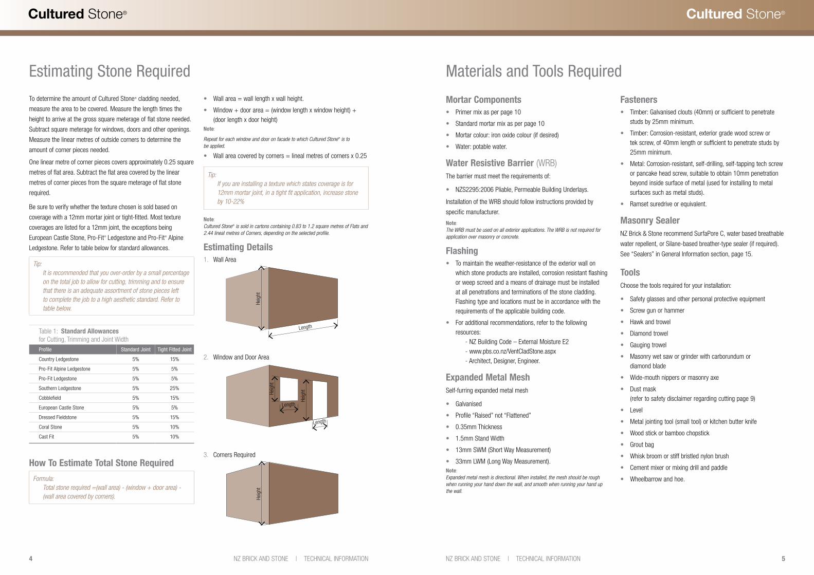
Estimating Stone Required
To determine the amount of Cultured Stone® cladding needed,
measure the area to be covered. Measure the length times the
height to arrive at the gross square meterage of flat stone needed.
Subtract square meterage for windows, doors and other openings.
Measure the linear metres of outside corners to determine the
amount of corner pieces needed.
One linear metre of corner pieces covers approximately 0.25 square
metres of flat area. Subtract the flat area covered by the linear
metres of corner pieces from the square meterage of flat stone
required.
Be sure to verify whether the texture chosen is sold based on
coverage with a 12mm mortar joint or tight-fitted. Most texture
coverages are listed for a 12mm joint, the exceptions being
European Castle Stone, Pro-Fit® Ledgestone and Pro-Fit® Alpine
Ledgestone. Refer to table below for standard allowances.
Tip: It is recommended that you over-order by a small percentage on the total job to allow for cutting, trimming and to ensure that there is an adequate assortment of stone pieces left to complete the job to a high aesthetic standard. Refer to table below.
How To Estimate Total Stone Required
Formula: Total stone required =(wall area) - (window + door area) - (wall area covered by corners).
• Wall area = wall length x wall height.
• Window + door area = (window length x window height) + (door length x door height)
Note:
Repeat for each window and door on facade to which Cultured Stone® is to be applied.
• Wall area covered by corners = lineal metres of corners x 0.25
Tip: If you are installing a texture which states coverage is for 12mm mortar joint, in a tight fit application, increase stone by 10-22%
Note:Cultured Stone® is sold in cartons containing 0.83 to 1.2 square metres of Flats and 2.44 lineal metres of Corners, depending on the selected profile.
Estimating Details1. Wall Area
2. Window and Door Area
3. Corners Required
Table 1: Standard Allowances for Cutting, Trimming and Joint Width
Profile Standard Joint Tight Fitted Joint
Country Ledgestone 5% 15%
Pro-Fit Alpine Ledgestone 5% 5%
Pro-Fit Ledgestone 5% 5%
Southern Ledgestone 5% 25%
Cobblefield 5% 15%
European Castle Stone 5% 5%
Dressed Fieldstone 5% 15%
Coral Stone 5% 10%
Cast Fit 5% 10%
Length
Heig
ht
Length
Length
Heig
ht
Heig
ht
Heig
ht
Mortar Components• Primer mix as per page 10
• Standard mortar mix as per page 10
• Mortar colour: iron oxide colour (if desired)
• Water: potable water.
Water Resistive Barrier (WRB)The barrier must meet the requirements of:
• NZS2295:2006 Pliable, Permeable Building Underlays.
Installation of the WRB should follow instructions provided by
specific manufacturer.
Note:The WRB must be used on all exterior applications. The WRB is not required for application over masonry or concrete.
Flashing• To maintain the weather-resistance of the exterior wall on
which stone products are installed, corrosion resistant flashing or weep screed and a means of drainage must be installed at all penetrations and terminations of the stone cladding. Flashing type and locations must be in accordance with the requirements of the applicable building code.
• For additional recommendations, refer to the following resources: - NZ Building Code – External Moisture E2 - www.pbs.co.nz/VentCladStone.aspx - Architect, Designer, Engineer.
Expanded Metal MeshSelf-furring expanded metal mesh
• Galvanised
• Profile “Raised” not “Flattened”
• 0.35mm Thickness
• 1.5mm Stand Width
• 13mm SWM (Short Way Measurement)
• 33mm LWM (Long Way Measurement).Note:Expanded metal mesh is directional. When installed, the mesh should be rough when running your hand down the wall, and smooth when running your hand up the wall.
Materials and Tools Required
Fasteners• Timber: Galvanised clouts (40mm) or sufficient to penetrate
studs by 25mm minimum.
• Timber: Corrosion-resistant, exterior grade wood screw or tek screw, of 40mm length or sufficient to penetrate studs by 25mm minimum.
• Metal: Corrosion-resistant, self-drilling, self-tapping tech screw or pancake head screw, suitable to obtain 10mm penetration beyond inside surface of metal (used for installing to metal surfaces such as metal studs).
• Ramset suredrive or equivalent.
Masonry SealerNZ Brick & Stone recommend SurfaPore C, water based breathable
water repellent, or Silane-based breather-type sealer (if required).
See “Sealers” in General Information section, page 15.
ToolsChoose the tools required for your installation:
• Safety glasses and other personal protective equipment
• Screw gun or hammer
• Hawk and trowel
• Diamond trowel
• Gauging trowel
• Masonry wet saw or grinder with carborundum or diamond blade
• Wide-mouth nippers or masonry axe
• Dust mask (refer to safety disclaimer regarding cutting page 9)
• Level
• Metal jointing tool (small tool) or kitchen butter knife
• Wood stick or bamboo chopstick
• Grout bag
• Whisk broom or stiff bristled nylon brush
• Cement mixer or mixing drill and paddle
• Wheelbarrow and hoe.
6 7NZ BRICK AND STONE | TECHNICAL INFORMATIONNZ BRICK AND STONE | TECHNICAL INFORMATION
Cultured Stone®Cultured Stone®
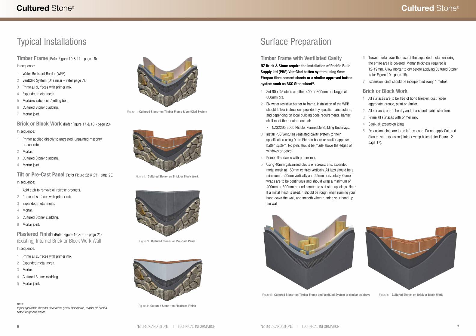
Typical Installations
Timber Frame (Refer Figure 10 & 11 - page 16)
In sequence:
1 Water Resistant Barrier (WRB).
2 VentClad System (Or similar – refer page 7).
3 Prime all surfaces with primer mix.
4 Expanded metal mesh.
5 Mortar/scratch coat/setting bed.
6 Cultured Stone® cladding.
7 Mortar joint.
Brick or Block Work (Refer Figure 17 & 18 - page 20)
In sequence:
1 Primer applied directly to untreated, unpainted masonry or concrete.
2 Mortar.
3 Cultured Stone® cladding.
4 Mortar joint.
Tilt or Pre-Cast Panel (Refer Figure 22 & 23 - page 23)
In sequence:
1 Acid etch to remove all release products.
2 Prime all surfaces with primer mix.
3 Expanded metal mesh.
4 Mortar.
5 Cultured Stone® cladding.
6 Mortar joint.
Plastered Finish (Refer Figure 19 & 20 - page 21) (Existing) Internal Brick or Block Work WallIn sequence:
1 Prime all surfaces with primer mix.
2 Expanded metal mesh.
3 Mortar.
4 Cultured Stone® cladding.
5 Mortar joint.
Note:If your application does not meet above typical installations, contact NZ Brick & Stone for specific advice.
Surface Preparation
Timber Frame with Ventilated CavityNZ Brick & Stone require the installation of Pacific Build
Supply Ltd (PBS) VentClad batten system using 9mm
Eterpan fibre cement sheets or a similar approved batten
system such as BGC Stonesheet®.
1 Set 90 x 45 studs at either 400 or 600mm crs Noggs at 800mm crs.
2 Fix water resistive barrier to frame. Installation of the WRB should follow instructions provided by specific manufacturer, and depending on local building code requirements, barrier shall meet the requirements of:
• NZS2295:2006 Pliable, Permeable Building Underlays.
3 Install PBS VentClad ventilated cavity system to their specification using 9mm Eterpan board or similar approved batten system. No joins should be made above the edges of windows or doors.
4 Prime all surfaces with primer mix.
5 Using 40mm galvanised clouts or screws, affix expanded metal mesh at 150mm centres vertically. All laps should be a minimum of 50mm vertically and 25mm horizontally. Corner wraps are to be continuous and should wrap a minimum of 400mm or 600mm around corners to suit stud spacings. Note: If a metal mesh is used, it should be rough when running your hand down the wall, and smooth when running your hand up the wall.
6 Trowel mortar over the face of the expanded metal, ensuring the entire area is covered. Mortar thickness required is
12-19mm. Allow mortar to dry before applying Cultured Stone® (refer Figure 10 - page 16).
7 Expansion joints should be incorporated every 4 metres.
Brick or Block Work1 All surfaces are to be free of bond breaker, dust, loose
aggregate, grease, paint or similar.
2 All surfaces are to be dry and of a sound stable structure.
3 Prime all surfaces with primer mix.
4 Caulk all expansion joints.
5 Expansion joints are to be left exposed. Do not apply Cultured
Stone® over expansion joints or weep holes (refer Figure 12 page 17).
Figure 1: Cultured Stone® on Timber Frame & VentClad System
Figure 2: Cultured Stone® on Brick or Block Work
Figure 3: Cultured Stone® on Pre-Cast Panel
Figure 4: Cultured Stone® on Plastered Finish
Figure 5: Cultured Stone® on Timber Frame and VentClad System or similar as above Figure 6 : Cultured Stone® on Brick or Block Work
8 9NZ BRICK AND STONE | TECHNICAL INFORMATIONNZ BRICK AND STONE | TECHNICAL INFORMATION
Cultured Stone®Cultured Stone®
Tilt or Pre-Cast Panel1 Tilt Panel surfaces are to be free of bond breaker, dust, loose
aggregate, grease, paint or similar.
2 All surfaces are to be dry and out of a stable structure.
3 Tilt up panel – acid etch to remove all release products.
4 Prime all surfaces with primer mix.
5 Affix expanded metal mesh at 150mm centres vertically and 400mm centres horizontally using 30mm Ramset ShureDrive Anchors (or similar equivalent). All laps should be a minimum of 50mm vertically and 25mm horizontally. Corner wraps are to be continuous, and should return around a corner a minimum 450mm. Note the correct side up in the form of the mesh; this is to aid in catching the mortar. When installed, the mesh should be rough when running your hand down the wall, and smooth when running your hand up the wall.
6 Trowel mortar over the face of the mesh ensuring the entire area is covered. Mortar thickness required is 12-19mm. Allow
mortar to dry before applying Cultured Stone®.
7 Caulk all expansion joints.
8 Expansion joints are to be left exposed. Do not apply Cultured
Stone® over expansion joints or weep holes (refer Figure 22 -
page 23).
» Surface Preparation
Plastered Finish (Existing) Internal Brick or Block Work Wall1 Set surface to be free of loose paint, dust, grease or similar.
2 Surface to be dry and of a stable structure.
3 Prime all surfaces with primer mix.
4 Affix expanded metal mesh, at 150mm centres vertically and 400mm centres horizontally using 30mm Ramset ShureDrive Anchors (or similar equivalent). All laps should be a minimum of 50mm vertically and 25mm horizontally. Corner wraps are to be continuous, and should return around a corner a minimum 600mm if possible. Note the correct side up in the form of the mesh; this is to aid in catching the mortar. When installed, the mesh should be rough when running your hand down the wall, and smooth when running your hand up the wall.
5 Trowel mortar over the face of the expanded metal, ensuring the entire area is covered. Mortar thickness required is
12-19mm. Allow mortar to dry before applying Cultured Stone® (refer Figure 20 - page 21).
6 Expansion joints should be incorporated every 4 metres.
Water Resistive Barrier (WRB)
When installing manufactured stone cladding in an exterior
application requiring a WRB; The barrier must meet the
requirements of:
• NZS2295:2006 Pliable, Permeable Building Underlays.
Installation of the WRB should follow instructions provided by
specific manufacturer.
Note:The WRB must be used on all exterior and interior mortar applications. The WRB is not required for application over masonry or concrete.
Important Note:It becomes the responsibility of the independent installer to ensure the structure upon which Cultured Stone® is being installed is structurally sound, and sufficient to sustain the weight of the Cultured Stone® product.For weight calculations; allow 74kg per square metre including mortar, 9mm Eterpan sheet (refer page 7) and Cultured Stone®.
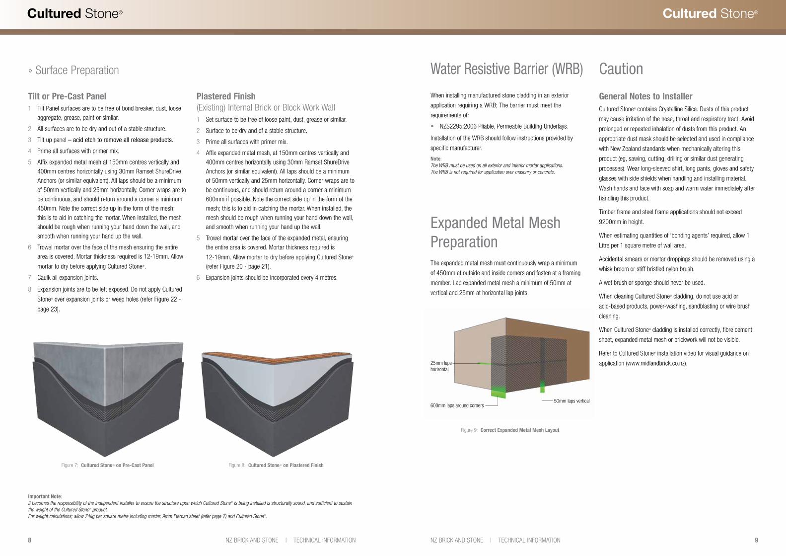
Figure 7: Cultured Stone® on Pre-Cast Panel Figure 8: Cultured Stone® on Plastered Finish
Figure 9: Correct Expanded Metal Mesh Layout
The expanded metal mesh must continuously wrap a minimum
of 450mm at outside and inside corners and fasten at a framing
member. Lap expanded metal mesh a minimum of 50mm at
vertical and 25mm at horizontal lap joints.
25mm laps horizontal
600mm laps around corners50mm laps vertical
Caution
Expanded Metal Mesh Preparation
General Notes to InstallerCultured Stone® contains Crystalline Silica. Dusts of this product
may cause irritation of the nose, throat and respiratory tract. Avoid
prolonged or repeated inhalation of dusts from this product. An
appropriate dust mask should be selected and used in compliance
with New Zealand standards when mechanically altering this
product (eg, sawing, cutting, drilling or similar dust generating
processes). Wear long-sleeved shirt, long pants, gloves and safety
glasses with side shields when handling and installing material.
Wash hands and face with soap and warm water immediately after
handling this product.
Timber frame and steel frame applications should not exceed
9200mm in height.
When estimating quantities of ‘bonding agents’ required, allow 1
Litre per 1 square metre of wall area.
Accidental smears or mortar droppings should be removed using a
whisk broom or stiff bristled nylon brush.
A wet brush or sponge should never be used.
When cleaning Cultured Stone® cladding, do not use acid or
acid-based products, power-washing, sandblasting or wire brush
cleaning.
When Cultured Stone® cladding is installed correctly, fibre cement
sheet, expanded metal mesh or brickwork will not be visible.
Refer to Cultured Stone® installation video for visual guidance on
application (www.midlandbrick.co.nz).

10 11NZ BRICK AND STONE | TECHNICAL INFORMATIONNZ BRICK AND STONE | TECHNICAL INFORMATION
Cultured Stone®Cultured Stone®
Primer and Mortar Mix
Primer
Primer Mix:• 4 parts by volume, liquid ‘bonding agent’
• 2 parts water
• 1 part General Purpose Portland Cement.
Mixing Primer:
Mix ‘bonding agent’ and water, add cement and mix to a milky
paste.
Applying Primer to Substrate
Apply primer mix to all substrates with a roller or brush as specified,
to the wall face where Cultured Stone® will be installed.
Tip: Typically allow one litre of bonding agent per square metre of wall area
Specialist Advice
NZ Brick & Stone recommend that advice be sort from companies
that specialise in pre-bagged mortars, bonding agents and other
appropriate additives in regards to the ‘Primer’ application and the
‘Mortar Mix’ for Cultured Stone.
Cemix Ltd www.cemix.co.nz
Dricon Ltd www.firth.co.nz/product-information/dricon
Mortar
Cultured Stone® Standard Mortar Mix:• 2 parts* washed sand, (sand is to be low in clay content)
• 1 part* general purpose Portland cement
• 2 litres of ‘bonding agent’
• Add water to desired consistency
• Colour oxide (if desired), no greater than 8.3% of cement content. Note: This only applies to the mortar to be used on the back and between the Cultured Stone.
*Use a 9 litre bucket to measure one part
Tip: If being installed over concrete, masonry or scratch coat substrate, the substrate surface area should also be dampened before applying mortar. Surfaces should appear damp but free of surface water.
Weather Conditions
Applications should be protected from temperatures below 5°
Celsius as mortar will not cure properly under such conditions.
Do not use antifreeze compounds to lower the freezing point
of mortar.
Mixing Mortar/Grout
Using Cultured Stone® standard mortar mix, mix to a firm, moist
consistency. Mortar that is too dry and crumbly will not provide
proper bond. Mortar that is too wet will be weak and untidy.
Mortar Colour
Mortar colour complements the colour of the stone being installed.
Example: Use tan mortar with earth-tone stones. This will greatly
enhance the appearance of the finished installation. Regular
mortars can be coloured to complement your Cultured Stone®
cladding using iron oxide pigments.
Applying Mortar to Prepared Surface Area
Using a hawk and trowel apply mortar 12mm to 19mm thick to
prepared surface in order to achieve a smooth even bed upon which
the stone can be applied. The surface may have a light combing to
improve adhesion of the stones. Allow to dry for 24 hours before the
stone is applied.
Application
Prepare Your Work Area
Tip: Spread Cultured Stone® cladding out at the job site so you have a good variety of sizes, shapes and colours to choose from.
Plan for some variety and contrast in the overall design. Use small
stones next to large ones, heavy-textured pieces next to smooth,
thick stones next to thinner ones. Mixing Cultured Stone® cladding
from different boxes during application will allow you to achieve a
desirable balance of stones on your finished project.
Applying Cultured Stone® CladdingSee page 15 for additional instructions concerning Pro-Fit™ Ledge-
stone, Pro-Fit™ Alpine Ledgestone and European Castle Stone.
Starting Point
Apply mortar and stone cladding working from the bottom up, or
from the top down.
Tip: Working from the top down may help avoid splashing previously applied stone with dripping mortar. Ledgestone types should be installed from the bottom up.
Joint Width
In order to obtain the most natural look, joints should be as narrow
as possible. The average should not exceed 12mm in width. An
attractive look can also be achieved by fitting stones tightly
together if desired. If using tight fit/drystack method, it is important
to make sure scratch coat/backing has been covered completely
by the setting bed of mortar. This will conceal the scratch coat/
backing and prevent pockets from forming behind stones that could
trap water.
Setting the Stone Cladding
Using the specified mortar mix, coloured if desired, apply a further
10 - 20mm of mortar to the back of each stone and press it onto
the prepared mortar bed. Apply pressure to the stone to ensure a
good bond and complete coverage between the mortar bed and
the back surface of the stone. The mortar will ooze out into the
gaps between each stone effectively forming the mortar joint that is
visible between each stone.
Tip: When stone cladding is installed correctly, fibre cement sheet, expanded metal mesh or brickwork will not be visible.
The mortar setting bed shall be between 10mm minimum and
35mm maximum. Care must be taken to avoid smearing mortar on
surface of the stone cladding.
Tip: Accidental smears or mortar droppings should be removed using a whisk broom or stiff bristled nylon brush only after mortar has become crumbly.
Install Corner Pieces
If your application requires corner pieces, apply these first. Notice
that the corner pieces have a long and a short leg. Alternate these
in opposite directions.
Install Flat Pieces
After the corner pieces are in place, flat pieces are applied working
toward the wall centre.
Keep Your Mortar Joints Consistent
Place the individual stones close together, creating uniform
joints between them. Cut and trim stones as required to achieve
consistent width in the mortar joints. Then trim and fit small pieces
into any remaining voids. (refer ‘Cutting and Trimming - page 12)

12 13NZ BRICK AND STONE | TECHNICAL INFORMATIONNZ BRICK AND STONE | TECHNICAL INFORMATION
Cultured Stone®Cultured Stone®
Cutting and Trimming
Stones can be cut and shaped for fit using wide-mouth nippers,
masonry axe, wet saw or angle grinder equipped with a dry cutting
diamond or carborundum blade. Some broken stones may be found
in the box. These also may be used in filling gaps and used for cuts.
Tip: For best finished appearance, coat cut or broken edges with mortar. If possible, position cut edges up when they are above eye level or down when below eye level. Place finished edges at exposed areas. Place cut edges within courses.
Note:Refer to page 38 - General Notes to Installer.
Level and Plumb Joint Lines
When applying Cobblefield™, European Castle Stone, Limestone,
Rockface, Coral or Ledgestone, endeavour to maintain level and
plumb joint lines. Also, long rectangular pieces will look most
natural if applied horizontally.
Ledgestone Types
When applying Ledgestone types, keep joints as small as possible
to maintain a natural look, and install from the bottom up. Strike
joints deeply, being careful not to expose the back edge of stones
or scratch coat/backing. See page 14 for additional instructions
regarding Pro-Fit™ Ledgestone, Pro-Fit™ Alpine Ledgestone and
European Castle Stone.
Note:Refer to Cultured Stone® Installation video for further information (www.midlandbrick.co.nz).
» Application
Grouting and Finishing Joints
Grouting Joints
If additional mortar is required, use a grout bag to fill in joints. Care
must be taken to avoid smearing mortar on surface of stone.
Tip: Accidental smears or mortar droppings should be removed only after mortar has become crumbly using a whisk broom or stiff bristled nylon brush. Never use a wet brush or wire brush.
Finishing Joints
When the mortar joints have become firm or “thumb-print” dry
(setting time will vary depending on wall surface and climatic
conditions), they should be pointed up with a wood stick, bamboo
chopstick (for tight joints) or metal jointing tool/kitchen butter
knife. Rake out excess mortar, compact and seal edges around
stones. Careful attention to proper and even jointing will result in a
professional looking finish.
Cleaning Finished Job
At the end of the work day, or when mortar is sufficiently set up, the
finished job should be broomed or brushed to remove loose mortar
and to clean the face of the stone.
Tip: A wet brush or sponge should never be used to treat the mortar joints as this will cause staining that will be difficult, or impossible, to remove. Do not use acid or acid-based products.
Note:Refer to Cultured Stone® Installation video for further information (www.midlandbrick.co.nz)).
Surface CleaningCare must be taken to avoid smearing mortar on the surface of
components. Accidental smears or mortar droppings should be
removed with a whisk broom or dry bristle brush only after mortar
has become crumbly.
Note:Do not use a wet brush, sponge or a wire brush. Do not use acid or acid-based products, power-washing, sandblasting or wire-brush cleaning.
» Application
Sill InstallationsSills provide a transition piece between a stone wainscot (sill) and
other exterior finishes and for water runoff. They can also be used
as a windowsill. Install using galvanised metal support brackets
with holding capacity minimum 25kg per lineal metre fastened with
galvanised nails or screws penetrating studs 25mm at a minimum
of 400mm centres.
Two brackets per sill is preferred if noggins are present. Use
construction adhesive to bond stone at bracket locations. Caulk
and flash as required at Watertable/Sill locations using an approved
corrosion resistive flashing that extends to the surface of exterior
wall finish and is installed to prevent water from re-entering the
exterior wall envelope. Failure to properly caulk/flash as described
in these installation directions may result in water damage to the
structure (refer Figure 24 & 25 - page 24 and Figure 35 - page 30).
Note:Refer to Cultured Stone® Installation video for further information (www.midlandbrick.co.nz).
Water FeaturesSimilar to other stone cladding products, NZ Brick & Stone does
not recommend using Cultured Stone® cladding for water feature
applications. However, some applications may be suitable. Refer to
your local representative.
Exterior Application Notes
Make sure that the application of Cultured Stone® cladding and
the structure they are being applied to incorporate good building
practices. Rigid, corrosion-resistant flashing shall be installed
at all wall penetrations. Flashing type and locations shall be in
accordance with the requirements of the applicable building code.
On exterior applications, the incorrect installation or absence of
flashing, gutters and downpipes may result in diversion of water
run-off onto finished surface areas. Masonry and other building
products subjected to these conditions may develop staining and,
when combined with severe freeze-thaw conditions, may eventually
cause damage. The application of Cultured Stone® cladding under
these conditions is not recommended.
Installation Over Existing CladdingOpportunities may be presented to re-clad a dwelling or building
using Cultured Stone over an existing cladding material not
addressed in this brochure. Discuss the possibility with your
architect/designer and NZ Brick & Stone when considered
necessary. Weathertightness and structural performance are the
two main considerations.
Capping Off Exposed Top of Exterior WallsTo achieve a finished architectural look on horizontal or sloping
top areas of exterior walls, piers, retaining walls or other surfaces,
Cultured Stone® Capstones or a poured in-place concrete cap must
be used to provide adequate run-off protection to the wall areas.
Caps should extend approximately 25-50mm beyond the finished
stone surface.
Cultured Stone® corner pieces, flat pieces, or hearthstones should
not be used to cap walls.
Retaining WallsAll retaining walls must be waterproofed at the fill side. The wall
construction should incorporate proper use of granular backfill and
provisions for good drainage. A continuous longitudinal drain along
the back of the wall set in drainage aggregate is recommended.
Chimney CapAll chimney chases must be capped with a cap that extends 25-
50mm beyond the finished stone surface to prevent water from
entering the wall system. Chimney or chase construction should
incorporate proper flashing.
14 15NZ BRICK AND STONE | TECHNICAL INFORMATIONNZ BRICK AND STONE | TECHNICAL INFORMATION
Cultured Stone®Cultured Stone®
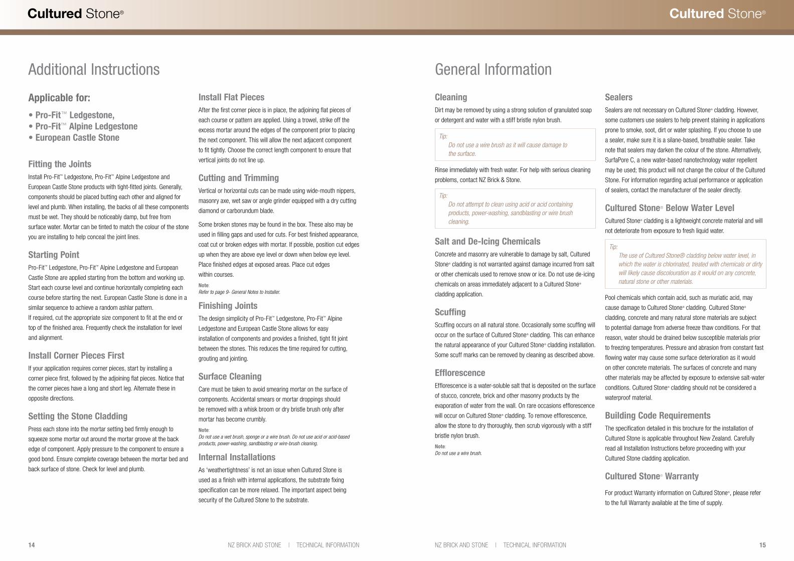
Additional Instructions
Applicable for:
• Pro-Fit™ Ledgestone, • Pro-Fit™ Alpine Ledgestone • European Castle Stone
Fitting the JointsInstall Pro-Fit™ Ledgestone, Pro-Fit™ Alpine Ledgestone and
European Castle Stone products with tight-fitted joints. Generally,
components should be placed butting each other and aligned for
level and plumb. When installing, the backs of all these components
must be wet. They should be noticeably damp, but free from
surface water. Mortar can be tinted to match the colour of the stone
you are installing to help conceal the joint lines.
Starting PointPro-Fit™ Ledgestone, Pro-Fit™ Alpine Ledgestone and European
Castle Stone are applied starting from the bottom and working up.
Start each course level and continue horizontally completing each
course before starting the next. European Castle Stone is done in a
similar sequence to achieve a random ashlar pattern.
If required, cut the appropriate size component to fit at the end or
top of the finished area. Frequently check the installation for level
and alignment.
Install Corner Pieces FirstIf your application requires corner pieces, start by installing a
corner piece first, followed by the adjoining flat pieces. Notice that
the corner pieces have a long and short leg. Alternate these in
opposite directions.
Setting the Stone CladdingPress each stone into the mortar setting bed firmly enough to
squeeze some mortar out around the mortar groove at the back
edge of component. Apply pressure to the component to ensure a
good bond. Ensure complete coverage between the mortar bed and
back surface of stone. Check for level and plumb.
Install Flat PiecesAfter the first corner piece is in place, the adjoining flat pieces of
each course or pattern are applied. Using a trowel, strike off the
excess mortar around the edges of the component prior to placing
the next component. This will allow the next adjacent component
to fit tightly. Choose the correct length component to ensure that
vertical joints do not line up.
Cutting and TrimmingVertical or horizontal cuts can be made using wide-mouth nippers,
masonry axe, wet saw or angle grinder equipped with a dry cutting
diamond or carborundum blade.
Some broken stones may be found in the box. These also may be
used in filling gaps and used for cuts. For best finished appearance,
coat cut or broken edges with mortar. If possible, position cut edges
up when they are above eye level or down when below eye level.
Place finished edges at exposed areas. Place cut edges
within courses.
Note:Refer to page 9- General Notes to Installer.
Finishing JointsThe design simplicity of Pro-Fit™ Ledgestone, Pro-Fit™ Alpine
Ledgestone and European Castle Stone allows for easy
installation of components and provides a finished, tight fit joint
between the stones. This reduces the time required for cutting,
grouting and jointing.
Surface CleaningCare must be taken to avoid smearing mortar on the surface of
components. Accidental smears or mortar droppings should
be removed with a whisk broom or dry bristle brush only after
mortar has become crumbly.
Note:Do not use a wet brush, sponge or a wire brush. Do not use acid or acid-based products, power-washing, sandblasting or wire-brush cleaning.
Internal InstallationsAs ‘weathertightness’ is not an issue when Cultured Stone is
used as a finish with internal applications, the substrate fixing
specification can be more relaxed. The important aspect being
security of the Cultured Stone to the substrate.
General Information
CleaningDirt may be removed by using a strong solution of granulated soap
or detergent and water with a stiff bristle nylon brush.
Tip: Do not use a wire brush as it will cause damage to the surface.
Rinse immediately with fresh water. For help with serious cleaning
problems, contact NZ Brick & Stone.
Tip: Do not attempt to clean using acid or acid containing products, power-washing, sandblasting or wire brush cleaning.
Salt and De-Icing ChemicalsConcrete and masonry are vulnerable to damage by salt, Cultured
Stone® cladding is not warranted against damage incurred from salt
or other chemicals used to remove snow or ice. Do not use de-icing
chemicals on areas immediately adjacent to a Cultured Stone®
cladding application.
ScuffingScuffing occurs on all natural stone. Occasionally some scuffing will
occur on the surface of Cultured Stone® cladding. This can enhance
the natural appearance of your Cultured Stone® cladding installation.
Some scuff marks can be removed by cleaning as described above.
EfflorescenceEfflorescence is a water-soluble salt that is deposited on the surface
of stucco, concrete, brick and other masonry products by the
evaporation of water from the wall. On rare occasions efflorescence
will occur on Cultured Stone® cladding. To remove efflorescence,
allow the stone to dry thoroughly, then scrub vigorously with a stiff
bristle nylon brush.
Note:Do not use a wire brush.
SealersSealers are not necessary on Cultured Stone® cladding. However,
some customers use sealers to help prevent staining in applications
prone to smoke, soot, dirt or water splashing. If you choose to use
a sealer, make sure it is a silane-based, breathable sealer. Take
note that sealers may darken the colour of the stone. Alternatively,
SurfaPore C, a new water-based nanotechnology water repellent
may be used; this product will not change the colour of the Cultured
Stone. For information regarding actual performance or application
of sealers, contact the manufacturer of the sealer directly.
Cultured Stone® Below Water LevelCultured Stone® cladding is a lightweight concrete material and will
not deteriorate from exposure to fresh liquid water.
Tip: The use of Cultured Stone® cladding below water level, in which the water is chlorinated, treated with chemicals or dirty will likely cause discolouration as it would on any concrete, natural stone or other materials.
Pool chemicals which contain acid, such as muriatic acid, may
cause damage to Cultured Stone® cladding. Cultured Stone®
cladding, concrete and many natural stone materials are subject
to potential damage from adverse freeze thaw conditions. For that
reason, water should be drained below susceptible materials prior
to freezing temperatures. Pressure and abrasion from constant fast
flowing water may cause some surface deterioration as it would
on other concrete materials. The surfaces of concrete and many
other materials may be affected by exposure to extensive salt-water
conditions. Cultured Stone® cladding should not be considered a
waterproof material.
Building Code RequirementsThe specification detailed in this brochure for the installation of
Cultured Stone is applicable throughout New Zealand. Carefully
read all Installation Instructions before proceeding with your
Cultured Stone cladding application.
Cultured Stone® Warranty
For product Warranty information on Cultured Stone®, please refer
to the full Warranty available at the time of supply.

16 17NZ BRICK AND STONE | TECHNICAL INFORMATIONNZ BRICK AND STONE | TECHNICAL INFORMATION
Cultured Stone®Cultured Stone®
Design Details
Figure 10: Timber Frame - Fibre Cement Clad Typical Construction (Dwg # CS-01.01)Note: Lightweight substrate applications should not exceed 9200mm in height.
Figure 11: Fibre Cement Clad - Plan (Dwg # CS-03.01)
Lightweight SubstratesNote: All drawings to be read in conjunction with Cultured Stone Technical Information Guide
90 x 45 stud framing @ 400 or 600mm ctrs
Water resistive barrier over studs
Prime all surfaces
10-35mm thick mortar bed
Expanded metal mesh fixed @ 150mm ctrs max with 40mm galv clouts lap 70mm.Corner wraps should be continuous
Selected Cultured Stone® cladding
Fibre cement sheeting (refer page 7)
VentClad system (or similar – refer page 7)
Note: Drawings not to scale
Lightweight SubstratesNote: All drawings to be read in conjunction with Cultured Stone Technical Information Guide
Figure 12: Fibre Cement Clad - Section (Dwg # CS-05.01)
Figure 13: Fibre Cement Clad Typical External Corner - Plan (Dwg # CS-02.01)
» Design Details
Water resistive barrier over studs
Prime all surfaces
VentClad system (or similar – refer page 7)
10-35mm thick mortar bed
90 x 45 studs framing @ 400 or 600mm ctrs
Selected Cultured Stone® cladding
Expanded metal mesh fixed @ 150mm ctrs max with 40mm galv clouts lap 70mm. Corner wraps should be continuous
Fibre cement sheeting (refer page 7)fixed to manufacturer’s specifications
90 x 45 stud framing @ 400 or 600mm ctrs
Water resistive barrier over studs
Interweave corners by alternating short end return orientations
Fibre cement sheeting (refer page 7)
VentClad system (or similar – refer page 7)
Prime all surfaces
Selected Cultured Stone® cladding
Expanded metal mesh fixed @ 150mm ctrs max with 40mm galv clouts lap 70mm. Corner wraps should be continuous.
10-35mm thick mortar bed
Timber frame
Water resistive barrier
‘VentClad’ system (or similar - refer page 7)
Fibre cement sheeting (refer page 7)
Prime surface
Expanded metal mesh
Cultured Stone®
Mortar bed
Mortar joint

18 19NZ BRICK AND STONE | TECHNICAL INFORMATIONNZ BRICK AND STONE | TECHNICAL INFORMATION
Cultured Stone®Cultured Stone®
Figure 14: Fibre Cement Clad Typical Internal Corner - Plan (Dwg # CS-02.02)
Figure 15: Typical Cladding Transition - Section (Dwg # CS-06.01)
90 x 45 stud framing @ 400 or 600mm ctrs
Interweave corners by alternating ends
Water resistive barrier over studs
Expanded metal mesh fixed @ 150mm ctrs max with 40mm galv clouts lap 70mm. Corner wraps should be continuous.
Prime all surfaces
VentClad system (or similar – refer page 7)
Selected Cultured Stone® cladding
Fibre cement sheeting (refer page 7)
10-35mm thick mortar bed
10-35mm thick mortar bed
Selected Cultured Stone® cladding
Prime all surfaces
Flashing by builder
Selected external cladding (alternative finishes may be used)
Fibre cement sheeting (refer page 7)
VentClad system (or similar – refer page 7)
Water resistive barrier over studs
90 x 45 studs framing @ 400 or 600mm ctrs
Expanded metal mesh fixed @ 150mm ctrs max with 40mm galv clouts lap 70mm. Corner wraps should be continuous.
» Design Details Lightweight SubstratesNote: All drawings to be read in conjunction with Cultured Stone Technical Information Guide
» Design Details
Figure 16: Fibre Cement Clad Base - Section (Dwg # CS-04.01)
Lightweight SubstratesNote: All drawings to be read in conjunction with Cultured Stone Technical Information Guide
Selected Cultured Stone® cladding
Expanded metal mesh fixed @ 150mm ctrs max with 40mm galv clouts lap 70mm. Corner wraps should be continuous.
Water resistive barrier over studs
50mm overhang
175mm min clearance to unprotected ground*
10-35mm thick mortar bed 90 x 45 stud framing @ 400 or 600mm ctrs
Prime all surfaces
VentClad system (or similar – refer page 7)
Fibre cement sheeting (refer page 7)
Concrete Slab to Engineer’s design
* Minimum levels change where ground is concreted or paved. Please check with local body requirements.

20 21NZ BRICK AND STONE | TECHNICAL INFORMATIONNZ BRICK AND STONE | TECHNICAL INFORMATION
Cultured Stone®Cultured Stone®
» Design Details Brick, Block and Concrete SubstratesNote: All drawings to be read in conjunction with Cultured Stone Technical Information Guide
Figure 17: Brick or Block Work Typical Construction (Dwg # CS-01.02)
Figure 18: Brick or Block Work Veneer - Plan (Dwg # CS-03.02)
10-35mm thick mortar bed
Selected Cultured Stone® cladding
Prime all surfaces
Existing brick or blockwork
Water resistive barrier over studs
Caulk all expansion joints.(Do not apply veneer over expansion joints)
Ensure surfaces are in original state ie free from dust, loose materials and any coatings and/or contaminants
Brick or blockwork
Prime surface
Mortar bed
Cultured Stone®
Mortar joint
Figure 19: Brick or Block Work Veneer - Section (Dwg # CS-05.02)
10-35mm thick mortar bed Selected Cultured Stone® cladding
Prime all surfaces Existing brick or blockwork
Ensure surfaces are in original state ie free from dust, loose materials and any coatings and/or contaminants
Figure 20: Plastered Internal Masonry Wall - Section (Dwg # CS-05.03)
10-35mm thick mortar bed
Selected Cultured Stone® cladding
Prime all surfaces
Concrete blockwork
Existing plaster finish
Ensure surfaces are in original state ie free from dust, loose materials and any coatings and/or contaminants
Expanded metal mesh mechanically fixed @ 150mm ctrs vertically and 400mm ctrs horizontally
» Design Details Brick, Block and Concrete SubstratesNote: All drawings to be read in conjunction with Cultured Stone Technical Information Guide
22 23NZ BRICK AND STONE | TECHNICAL INFORMATIONNZ BRICK AND STONE | TECHNICAL INFORMATION
Cultured Stone®Cultured Stone®
» Design Details Brick, Block and Concrete SubstratesNote: All drawings to be read in conjunction with Cultured Stone Technical Information Guide
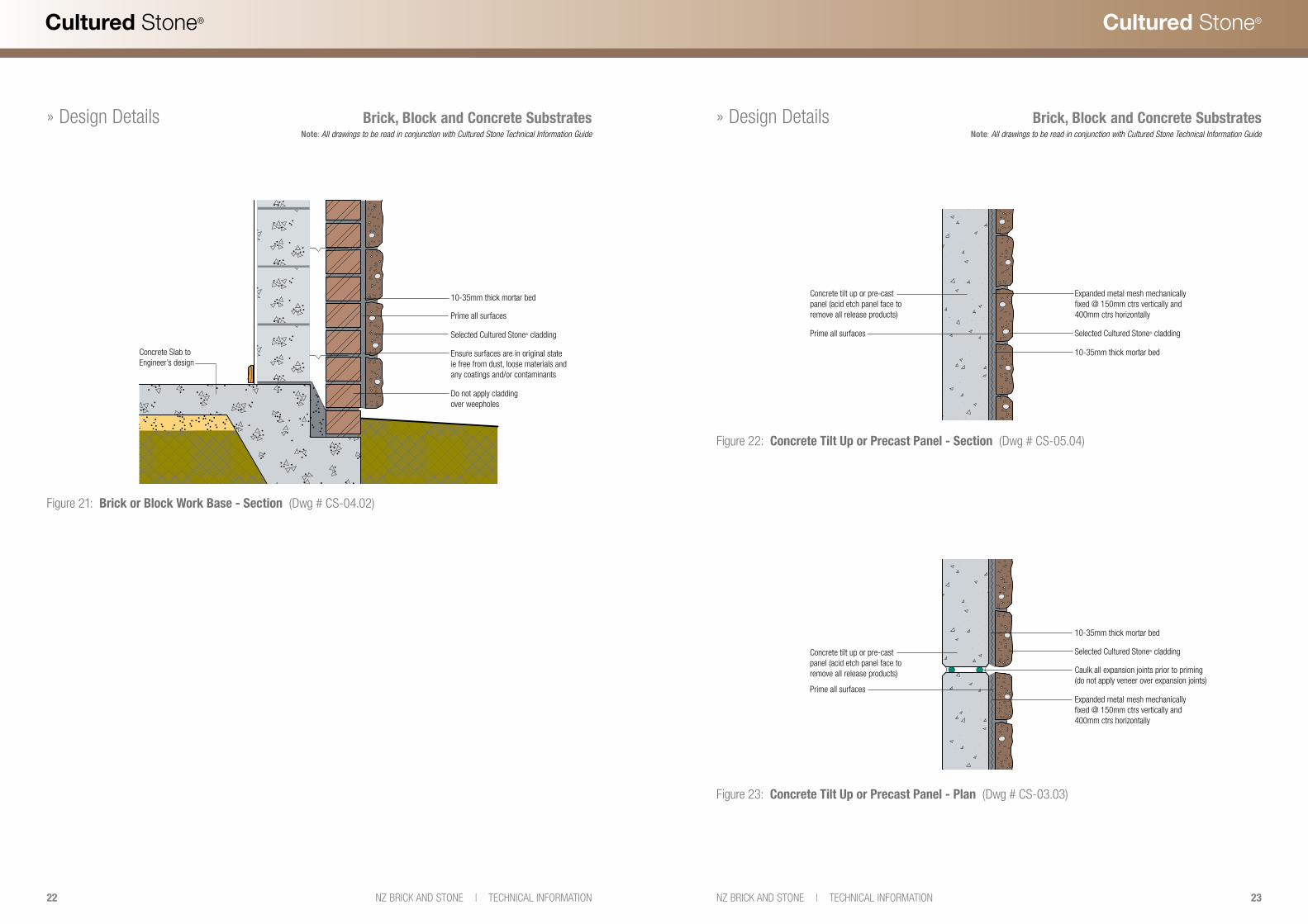
Figure 21: Brick or Block Work Base - Section (Dwg # CS-04.02)
10-35mm thick mortar bed
Selected Cultured Stone® cladding
Do not apply cladding over weepholes
Prime all surfaces
Concrete Slab to Engineer’s design
Ensure surfaces are in original state ie free from dust, loose materials and any coatings and/or contaminants
» Design Details Brick, Block and Concrete SubstratesNote: All drawings to be read in conjunction with Cultured Stone Technical Information Guide
Figure 23: Concrete Tilt Up or Precast Panel - Plan (Dwg # CS-03.03)
10-35mm thick mortar bed
Selected Cultured Stone® cladding
Prime all surfaces Expanded metal mesh mechanically fixed @ 150mm ctrs vertically and 400mm ctrs horizontally
Concrete tilt up or pre-cast panel (acid etch panel face to remove all release products) Caulk all expansion joints prior to priming
(do not apply veneer over expansion joints)
Figure 22: Concrete Tilt Up or Precast Panel - Section (Dwg # CS-05.04)
10-35mm thick mortar bed
Selected Cultured Stone® cladding Prime all surfaces
Expanded metal mesh mechanically fixed @ 150mm ctrs vertically and 400mm ctrs horizontally
Concrete tilt up or pre-cast panel (acid etch panel face to remove all release products)

24 25NZ BRICK AND STONE | TECHNICAL INFORMATIONNZ BRICK AND STONE | TECHNICAL INFORMATION
Cultured Stone®Cultured Stone®
» Design Details Cladding Transitions and Window JunctionsNote: All drawings to be read in conjunction with Cultured Stone Technical Information Guide
Figure 24: Sill Render Transition - Section (Dwg # CS-06.02)Note: Lightweight substrate applications should not exceed 9200mm in height. All drawings to be read in conjunction with Cultured Stone Technical Information Guide
Figure 25: Sill Cladding Transition - Section (Dwg # CS-06.03)
45776
63 50
3 SILL - FRONT ELEVATIONSILL - SECTION
10-35mm thick mortar bed
Selected Cultured Stone® cladding
Prime all surfaces
Ensure surfaces are in original state ie free from dust, loose materials and any coatings and/or contaminants
Water resistive barrier over studs
Existing brick or blockwork Render finish
Flashing with drip edge
Seal under flashing with caulking
Metal support angle 30 x 30 x 3 screw fixed @ 600mm ctrs max
10-35mm thick mortar bed
Selected Cultured Stone® cladding
Prime all surfaces
Expanded metal mesh fixed @ 150mm ctrs max with 40mm galv clouts lap 70mm. Corner wraps should be continuous.
Fibre cement sheeting(refer page 7)
Water resistive barrier over studs
90 x 45 stud framing @ 400 or 600mm ctrs
Nogging optional
VentClad system (or similar – refer page 7)
Selected external cladding (alternative finishes may be used)
Flashing with drip edge
Seal under flashing with caulking
Metal support angle 30 x 30 x 3 screw fixed @ 600mm ctrs max
45776
63 50
3 SILL - FRONT ELEVATIONSILL - SECTION
» Design Details Cladding Transitions and Window JunctionsNote: All drawings to be read in conjunction with Cultured Stone Technical Information Guide
Figure 27: Typical Window Sill - Section (Dwg # CS-06.05)
Figure 26: Sill at Window - Section (Dwg # CS-06.04)
Selected Cultured Stone® cladding
Expanded metal mesh fixed @ 150mm ctrs max with 40mm galv clouts lap 70mm. Corner wraps should be continuous.
Water resistive barrier over studs
Casing bead
Caulking
6mm nominal
10-35mm thick mortar bed
90 x 45 stud framing @ 400 or 600mm ctrs
Flashing by builder.Refer manufacturer’s details
Prime all surfaces
VentClad system (or similar – refer page 7)
Fibre cement sheeting(refer page 7)
Drawings are diagrammatic only, refer to window manufacturers specifications and details for the ‘VentClad System’ on www.pbs.co.nz/VentClad plus your architect’s detailing.
Prime all surfaces
VentClad system (or similar – refer page 7)
Fibre cement sheeting(refer page 7)
Water resistive barrier over studs
90 x 45 stud framing @ 400 or 600mm ctrs
Flashing by builder refer manufacturer’s details
Drawings are diagrammatic only, refer to window manufacturers specifications and details for the ‘VentClad System’ on www.pbs.co.nz/VentClad plus your architect’s detailing.
Note:Window frames profile/position will vary. Refer manufacturer’s specifications for installation/flashing details
Selected Cultured Stone® cladding
Expanded metal mesh fixed @ 150mm ctrs max with 40mm galv clouts lap 70mm. Corner wraps should be continuous.
Metal bracket
Galv timber screws 25mm min
Watertable / Sill
Casing bead
Caulking
6mm nominal
10-35mm thick mortar bed

26 27NZ BRICK AND STONE | TECHNICAL INFORMATIONNZ BRICK AND STONE | TECHNICAL INFORMATION
Cultured Stone®Cultured Stone®
» Design Details Cladding Transitions and Window JunctionsNote: All drawings to be read in conjunction with Cultured Stone Technical Information Guide
Figure 28: Typical Window Head - Section (Dwg # CS-07.01)
Drawings are diagrammatic only, refer to window manufacturers specifications and details for the ‘VentClad System’ on www.pbs.co.nz/VentClad plus your architect’s detailing.
Fibre cement sheeting(refer page 7)
Header trimmer
Window frame
90 x 45 stud framing @ 400 or 600mm ctrs
VentClad system (or similar – refer page 7)
Selected Cultured Stone® cladding
Prime all surfaces
Expanded metal mesh fixed @ 150mm ctrs max with 40mm galv clouts lap 70mm. Corner wraps should be continuous.
Water resistive barrier over studs
Approved weep screed
6mm nominal
10-35mm thick mortar bed
VentClad system (or similar – refer page 7)
Flashing by builder, refer manufacturer’s details
Figure 29: Sill at Window - Section (Dwg # CS-06.06)
10-35mm thick mortar bed
Selected Cultured Stone® cladding
Prime all surfaces
Ensure surfaces are in original state ie free from dust, loose materials and any coatings and/or contaminants
Internal 150mm or 200mm block wall
Caulking
Window frame
Cultured Stone® wall cap used as sill - cut to suit. Slope sill at a minimum 15˚
Drawings are diagrammatic only, refer to window manufacturers specifications and details for the ‘VentClad System’ on www.pbs.co.nz/VentClad plus your architect’s detailing.
Figure 30: Typical Raking Fascia - Section (Dwg # CS-09.01)
Figure 31: Typical Raking Eave - Section (Dwg # CS-09.02)
Fascias and EavesNote: All drawings to be read in conjunction with Cultured Stone Technical Information Guide
10-35mm thick mortar bed
Selected Cultured Stone® cladding
Prime all surfaces
25mm min lap
Fibre cement sheeting(refer page 7)
VentClad system (or similar – refer page 7)
Water resistive barrier over studs
90 x 45 studs framing @ 400 or 600mm ctrs
Use caulking/joint sealer where wind driven rain is an issue
Expanded metal mesh fixed @ 150mm ctrs max with 40mm galv clouts lap 70mm. Corner wraps should be continuous.
Refer VentClad details and architect’s drawings
Soffit lining
Storm mould/bead
10-35mm thick mortar bed
Selected Cultured Stone® cladding
Prime all surfaces
Fibre cement sheeting(refer page 7)
VentClad system (or similar – refer page 7)
Water resistive barrier over studs
90 x 45 studs framing @ 400 or 600mm ctrs
Expanded metal mesh fixed @ 150mm ctrs max with 40mm galv clouts lap 70mm. Corner wraps should be continuous.
Refer VentClad details and architect’s drawings
» Design Details
28 29NZ BRICK AND STONE | TECHNICAL INFORMATIONNZ BRICK AND STONE | TECHNICAL INFORMATION
Cultured Stone®Cultured Stone®
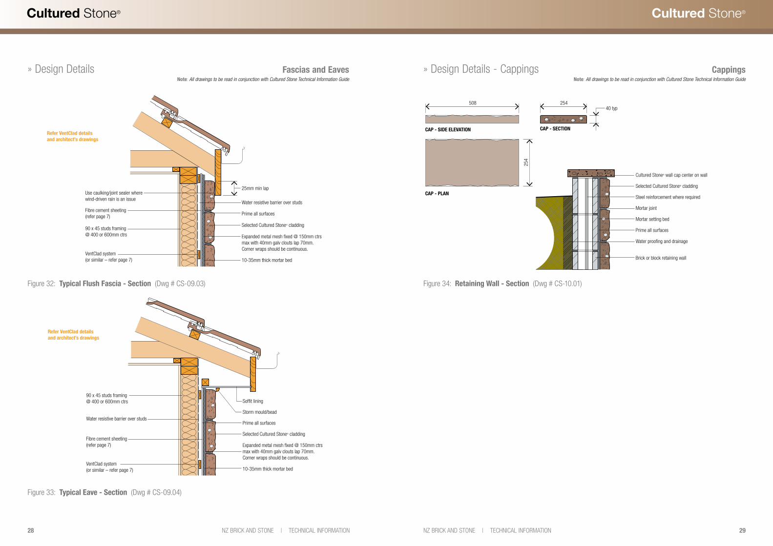
Figure 32: Typical Flush Fascia - Section (Dwg # CS-09.03)
Figure 33: Typical Eave - Section (Dwg # CS-09.04)
10-35mm thick mortar bed
Selected Cultured Stone® cladding
Prime all surfaces Fibre cement sheeting(refer page 7)
Water resistive barrier over studs
90 x 45 studs framing @ 400 or 600mm ctrs
VentClad system (or similar – refer page 7)
Expanded metal mesh fixed @ 150mm ctrs max with 40mm galv clouts lap 70mm. Corner wraps should be continuous.
Use caulking/joint sealer where wind-driven rain is an issue
25mm min lap
Refer VentClad details and architect’s drawings
10-35mm thick mortar bed
Selected Cultured Stone® cladding
Prime all surfaces
Fibre cement sheeting(refer page 7)
VentClad system (or similar – refer page 7)
Water resistive barrier over studs
90 x 45 studs framing @ 400 or 600mm ctrs
Expanded metal mesh fixed @ 150mm ctrs max with 40mm galv clouts lap 70mm. Corner wraps should be continuous.
Soffit lining
Storm mould/bead
Refer VentClad details and architect’s drawings
» Design Details Fascias and EavesNote: All drawings to be read in conjunction with Cultured Stone Technical Information Guide
Figure 34: Retaining Wall - Section (Dwg # CS-10.01)
254
254508
CAP - SIDE ELEVATION
CAP - PLAN
CAP - SECTION
Selected Cultured Stone® cladding
Steel reinforcement where required
Mortar joint
40 typ
Mortar setting bed
Prime all surfaces
Water proofing and drainage
Brick or block retaining wall
Cultured Stone® wall cap center on wall
» Design Details - Cappings CappingsNote: All drawings to be read in conjunction with Cultured Stone Technical Information Guide
30 31NZ BRICK AND STONE | TECHNICAL INFORMATIONNZ BRICK AND STONE | TECHNICAL INFORMATION
Cultured Stone®Cultured Stone®
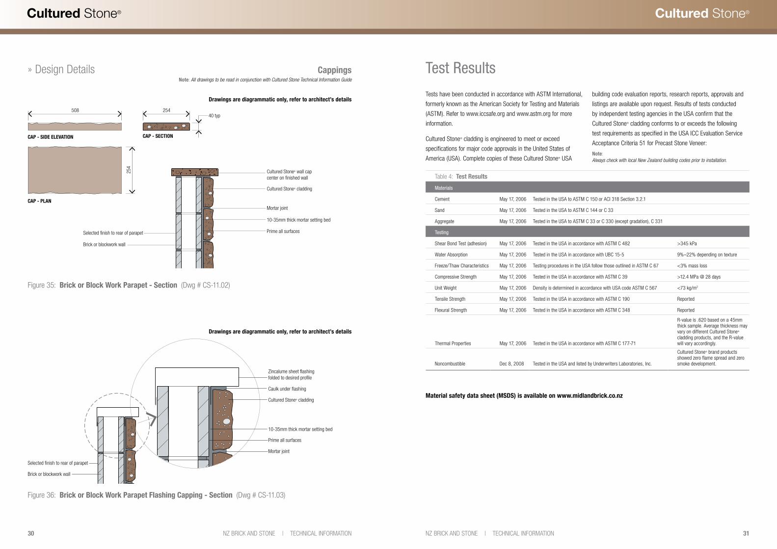
Figure 35: Brick or Block Work Parapet - Section (Dwg # CS-11.02)
Figure 36: Brick or Block Work Parapet Flashing Capping - Section (Dwg # CS-11.03)
Cultured Stone® cladding
Selected finish to rear of parapet
Mortar joint
10-35mm thick mortar setting bed
Prime all surfaces
Brick or blockwork wall
Cultured Stone® wall cap center on finished wall
254508
CAP - SIDE ELEVATION
CAP - PLAN
CAP - SECTION
40 typ
254
Selected finish to rear of parapet
Brick or blockwork wall
Cultured Stone® cladding
Mortar joint
10-35mm thick mortar setting bed
Prime all surfaces
Caulk under flashing
Zincalume sheet flashing folded to desired profile
» Design Details CappingsNote: All drawings to be read in conjunction with Cultured Stone Technical Information Guide
Drawings are diagrammatic only, refer to architect’s details
Drawings are diagrammatic only, refer to architect’s details
Test Results
Tests have been conducted in accordance with ASTM International,
formerly known as the American Society for Testing and Materials
(ASTM). Refer to www.iccsafe.org and www.astm.org for more
information.
Cultured Stone® cladding is engineered to meet or exceed
specifications for major code approvals in the United States of
America (USA). Complete copies of these Cultured Stone® USA
Table 4: Test Results
Materials
Cement May 17, 2006 Tested in the USA to ASTM C 150 or ACI 318 Section 3.2.1
Sand May 17, 2006 Tested in the USA to ASTM C 144 or C 33
Aggregate May 17, 2006 Tested in the USA to ASTM C 33 or C 330 (except gradation), C 331
Testing
Shear Bond Test (adhesion) May 17, 2006 Tested in the USA in accordance with ASTM C 482 >345 kPa
Water Absorption May 17, 2006 Tested in the USA in accordance with UBC 15-5 9%–22% depending on texture
Freeze/Thaw Characteristics May 17, 2006 Testing procedures in the USA follow those outlined in ASTM C 67 <3% mass loss
Compressive Strength May 17, 2006 Tested in the USA in accordance with ASTM C 39 >12.4 MPa @ 28 days
Unit Weight May 17, 2006 Density is determined in accordance with USA code ASTM C 567 <73 kg/m2
Tensile Strength May 17, 2006 Tested in the USA in accordance with ASTM C 190 Reported
Flexural Strength May 17, 2006 Tested in the USA in accordance with ASTM C 348 Reported
Thermal Properties May 17, 2006 Tested in the USA in accordance with ASTM C 177-71
R-value is .620 based on a 45mm thick sample. Average thickness may vary on different Cultured Stone® cladding products, and the R-value will vary accordingly.
Noncombustible Dec 8, 2008 Tested in the USA and listed by Underwriters Laboratories, Inc.
Cultured Stone® brand products showed zero flame spread and zero smoke development.
building code evaluation reports, research reports, approvals and
listings are available upon request. Results of tests conducted
by independent testing agencies in the USA confirm that the
Cultured Stone® cladding conforms to or exceeds the following
test requirements as specified in the USA ICC Evaluation Service
Acceptance Criteria 51 for Precast Stone Veneer:
Note:Always check with local New Zealand building codes prior to installation.
Material safety data sheet (MSDS) is available on www.midlandbrick.co.nz

contact usToll Free: 0800 MIDLAND (0800 643 5263)Email: [email protected]
or visit our website at www.midlandbrick.co.nz
Head Office:Midland Brick NZNZ Brick & Stone8 Cowley Place, Rosedale, Albany Auckland, New ZealandPh: 09 414 1075Fax: 09 414 1073
Lower North Island:Creative Brick & Stone102 Kapiti Rd, ParaparaumuNew ZealandChris Marshall: 021 854 811Fax: 04 234 6646
South Island:Brick & Stone SI35 Edmonton Rd, Hornby SouthChristchurch, New ZealandPh: 03 343 6620Fax: 03 343 6629
Proudly 100%NZ Owned &Operated


