Mitglied der Helmholtz-Gemeinschaft Joint European Summer School for Fuel Cell and Hydrogen Technology Heraklion, Crete 21st September 2012 Solid Oxide Fuel Cells Current Research & Development Issues Robert Mücke Forschungszentrum Jülich GmbH, Institute of Energy and Climate Research (IEK-1: Materials Synthesis and Processing) 2 Robert Mücke, Joint European Summer School for Fuel Cell and Hydrogen Technology Higher cell performce / lower temperatures thin-film technology new materials (next generation) Higher stack performce contacting the cell Industrialization Scalable and cheap manufacturing, materials, components Overview of Research Fields Long-term stability >40.000h protective coatings accelerated testing Cycling reoxidation, thermal, electrical load Fuel issues coking, sulphur System / Balance of plant operating the stack suiteable components stack sealing Material solution Materials / design / processing of cell & stacks System solution System / BoP / operating conditions
Transcript
Mitg
lied
der
He
lmho
ltz-G
eme
insc
haft
Joint European Summer School for Fuel Cell and Hydrogen TechnologyHeraklion, Crete21st September 2012
Solid Oxide Fuel Cells
Current Research & Development
IssuesRobert Mücke
Forschungszentrum Jülich GmbH, Institute of Energy and Climate Research(IEK-1: Materials Synthesis and Processing)
2 Robert Mücke, Joint European Summer School for Fuel Cell and Hydrogen Technology
Higher cell performce/ lower temperatures
thin-film technologynew materials
(next generation)
Higher stack performcecontacting the cell
IndustrializationScalable and cheap
manufacturing,materials, components
Overview of Research Fields
Long-term stability>40.000h
protective coatingsaccelerated testing
Cyclingreoxidation, thermal,
electrical load
Fuel issuescoking, sulphur
System / Balance of plant
operating the stacksuiteable components
stack sealing
Material solutionMaterials / design /
processing of cell & stacks
System solutionSystem / BoP /
operating conditions
3 Robert Mücke, Joint European Summer School for Fuel Cell and Hydrogen Technology
1. Increasing the Cell Perfomance
2. Cell vs. Stack Performance
3. Long term stability / Degradation
4. Stack Sealing
5. Reoxidation
6. Fuel & Fuel impurities
7. Metall Supported Cells (MSC)
8. Mass Manufacturing
Contents
4 Robert Mücke, Joint European Summer School for Fuel Cell and Hydrogen Technology
1. Increasing the Cell Performance
5 Robert Mücke, Joint European Summer School for Fuel Cell and Hydrogen Technology
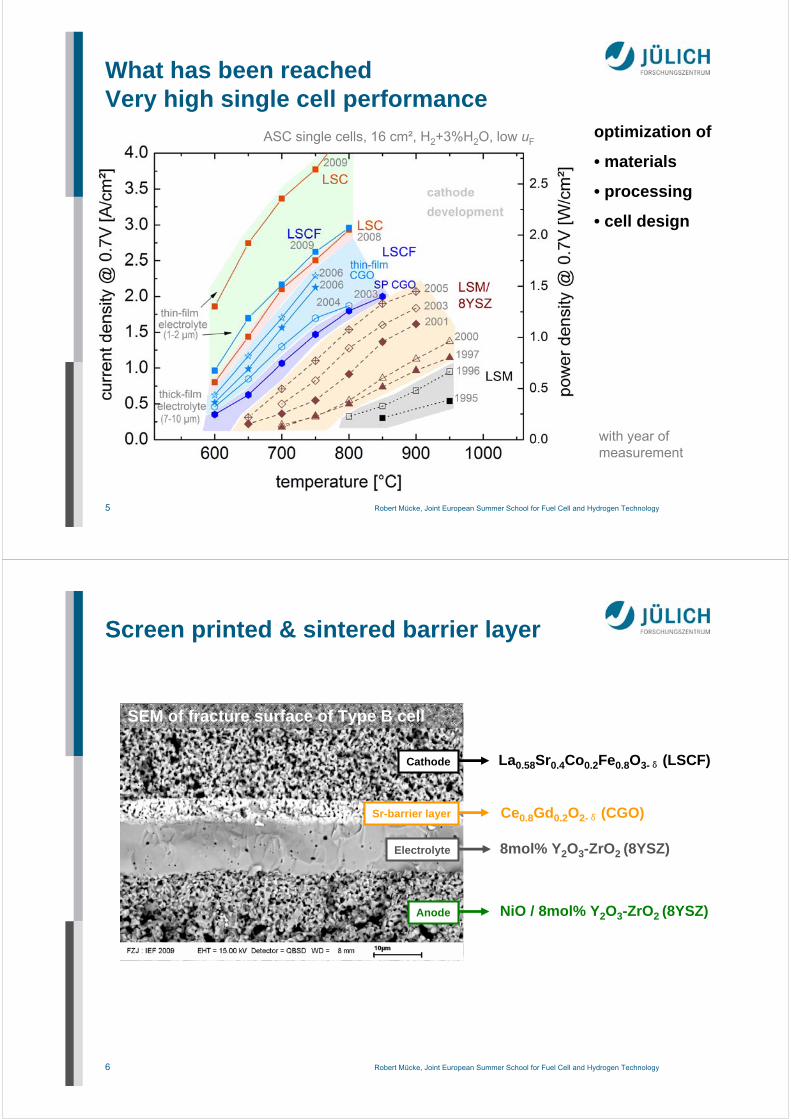
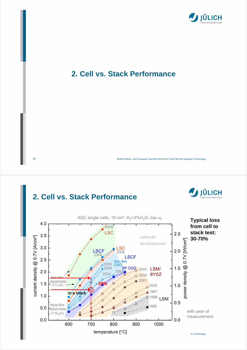
What has been reachedVery high single cell performance
ASC single cells, 16 cm², H2+3%H2O, low uF
with year of measurement
optimization of
• materials
• processing
• cell design
6 Robert Mücke, Joint European Summer School for Fuel Cell and Hydrogen Technology
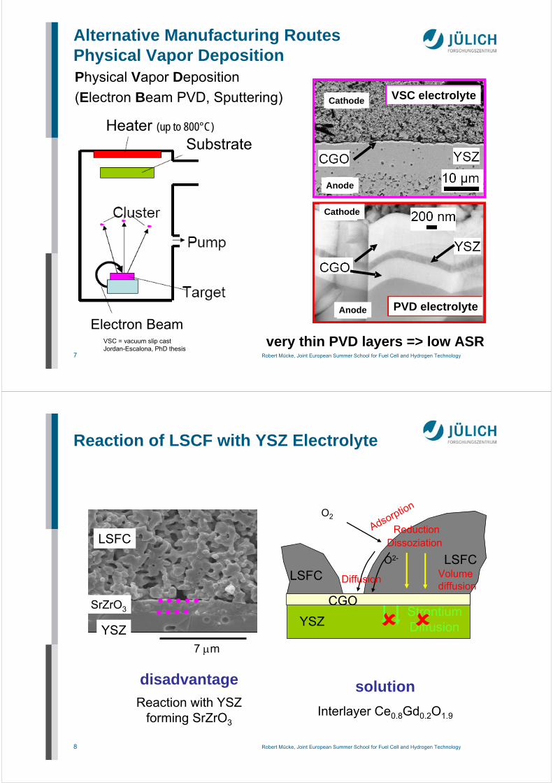
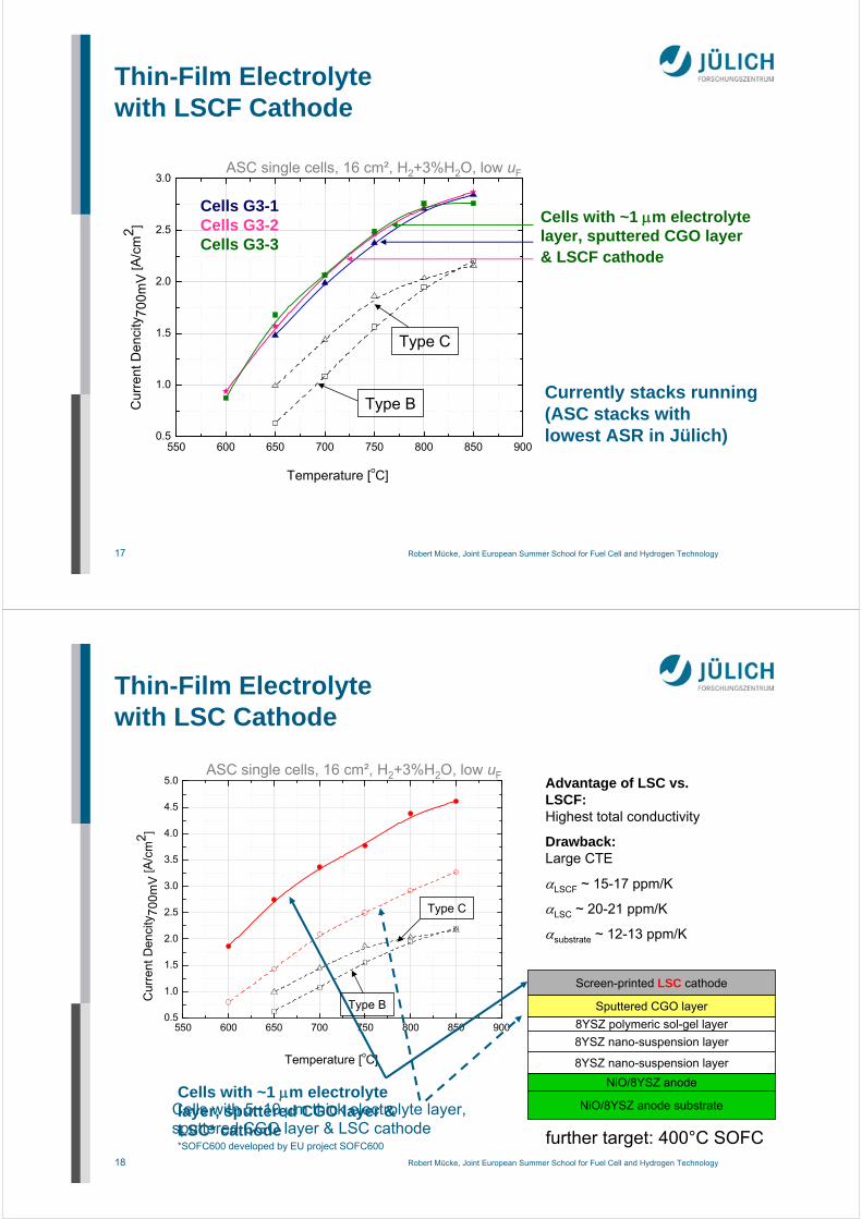
NiO / 8mol% Y2O3-ZrO2 (8YSZ)
8mol% Y2O3-ZrO2 (8YSZ)
La0.58Sr0.4Co0.2Fe0.8O3-δ (LSCF)
Ce0.8Gd0.2O2-δ (CGO)
Anode
Electrolyte
Sr-barrier layer
Cathode
SEM of fracture surface of Type B cell
Screen printed & sintered barrier layer
7 Robert Mücke, Joint European Summer School for Fuel Cell and Hydrogen Technology
Alternative Manufacturing RoutesPhysical Vapor DepositionPhysical Vapor Deposition
(Electron Beam PVD, Sputtering)
SubstrateHeater (up to 800°C)
Electron Beamvery thin PVD layers => low ASR
PVD electrolyte
VSC electrolyte
VSC = vacuum slip castJordan-Escalona, PhD thesis
Anode
Anode
Cathode
Cathode
8 Robert Mücke, Joint European Summer School for Fuel Cell and Hydrogen Technology
O2
Adsorption
Dissoziation
Diffusion
O2-
YSZ
LSFCLSFC
Reduction
Volumediffusion
disadvantage
Reaction with YSZ forming SrZrO3
StrontiumDiffusion
7 m
LSFC
YSZ
SrZrO3
Reaction of LSCF with YSZ Electrolyte
solution
Interlayer Ce0.8Gd0.2O1.9
CGO
9 Robert Mücke, Joint European Summer School for Fuel Cell and Hydrogen Technology
EDX scanSr enrichment
Sr Ce
Screen printedCGO
(TS=1300 °C)
cathode
YSZ electrolyte
1 m
(TS=1040 °C)
1 m
CGO PVD 800 °C
YSZ
1.2.
3.
1. Sr diffusion to YSZ, not with PVD barrier2. Solid state solution of CGO and YSZ, not found with PVD barrier3. Microstructure: • Screen printed + sintered: sponge-like structure
longer pathways for O2–
• PVD layers: laminar, tight contact between
YSZ and CGO layer (less CGO/LSCF contact)
Screen Printed CGO Barrier Layersvs. PVD Layers
10 Robert Mücke, Joint European Summer School for Fuel Cell and Hydrogen Technology
0.0 0.2 0.4 0.6 0.8 1.0 1.2
0.6
0.7
0.8
0.9
1.0
1.1
current density (A/cm2)
EB-PVD, 800 °C EB-PVD, 400 °C
Toperation
=700 °C
Ce0.8
Gd0.2
O2-
Ce0.9
Gd0.1
O2-
sputtered, 400 °C
sinteredCGO layers
CGO layers by PVD
800 °C 700 °C
0.0 0.2 0.4 0.6 0.8 1.0 1.2
0.8
0.9
1.0
1.1
Ce0.8
Gd0.2
O2-
Ce0.9
Gd0.1
O2-
sputtered, 400 °C EB-PVD, 400 °C EB-PVD, 800 °C
cell
volta
ge
(V
)
current density (A/cm2)
sinteredCGO layers
CGO layers by PVD
TOperation
=800 °C
• PVD CGO performs significantly better than sintered CGO barrier,especially at lower operating temperatures
• at 700°C: sintered: 1.0 A/cm²; PVD barrier: 1.7 A/cm² (@0.7V)• Ce0.8Gd0.2O2- performs better than Ce0.9Gd0.1O2-
Temperature of operation:
Different CGO Barrier LayersElectrochemical Performance
11 Robert Mücke, Joint European Summer School for Fuel Cell and Hydrogen Technology
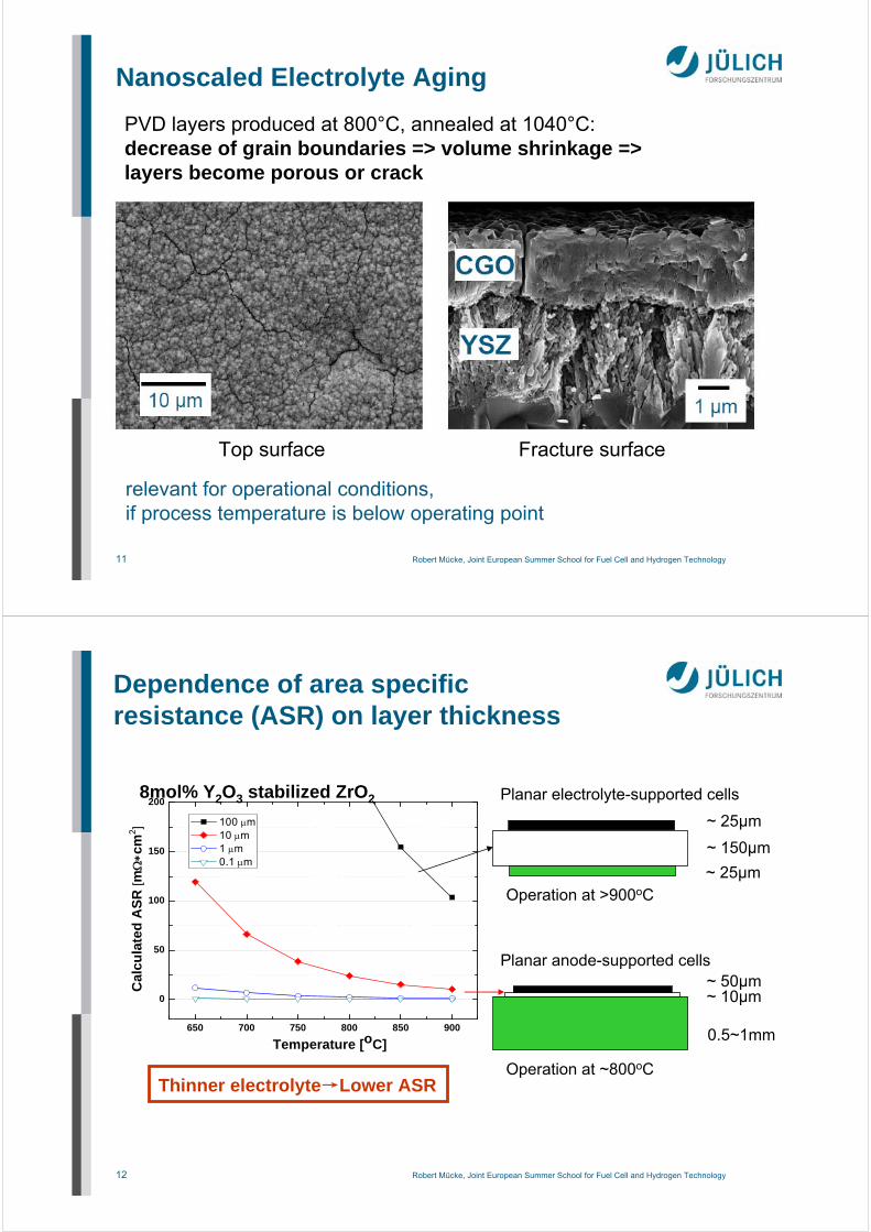
Nanoscaled Electrolyte Aging
Top surface Fracture surface
PVD layers produced at 800°C, annealed at 1040°C:decrease of grain boundaries => volume shrinkage =>layers become porous or crack
relevant for operational conditions, if process temperature is below operating point
12 Robert Mücke, Joint European Summer School for Fuel Cell and Hydrogen Technology
650 700 750 800 850 900
0
50
100
150
200
100 m 10 m 1 m 0.1 m
Cal
cu
late
d A
SR
[mc
m2 ]
Temperature [oC]
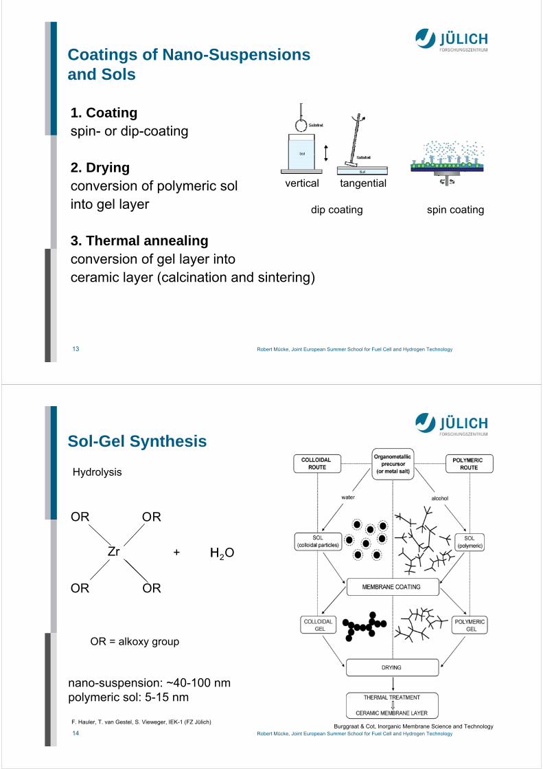
~ 150µm
~ 25µm
~ 25µm
~ 50µm~ 10µm
0.5~1mm
Planar electrolyte-supported cells
Operation at >900oC
Operation at ~800oCThinner electrolyte→Lower ASR
Planar anode-supported cells
8mol% Y2O3 stabilized ZrO2
Dependence of area specific resistance (ASR) on layer thickness
13 Robert Mücke, Joint European Summer School for Fuel Cell and Hydrogen Technology
Coatings of Nano-Suspensionsand Sols
1. Coatingspin- or dip-coating
2. Dryingconversion of polymeric solinto gel layer
3. Thermal annealingconversion of gel layer intoceramic layer (calcination and sintering)
vertical tangential
dip coating spin coating
14 Robert Mücke, Joint European Summer School for Fuel Cell and Hydrogen Technology
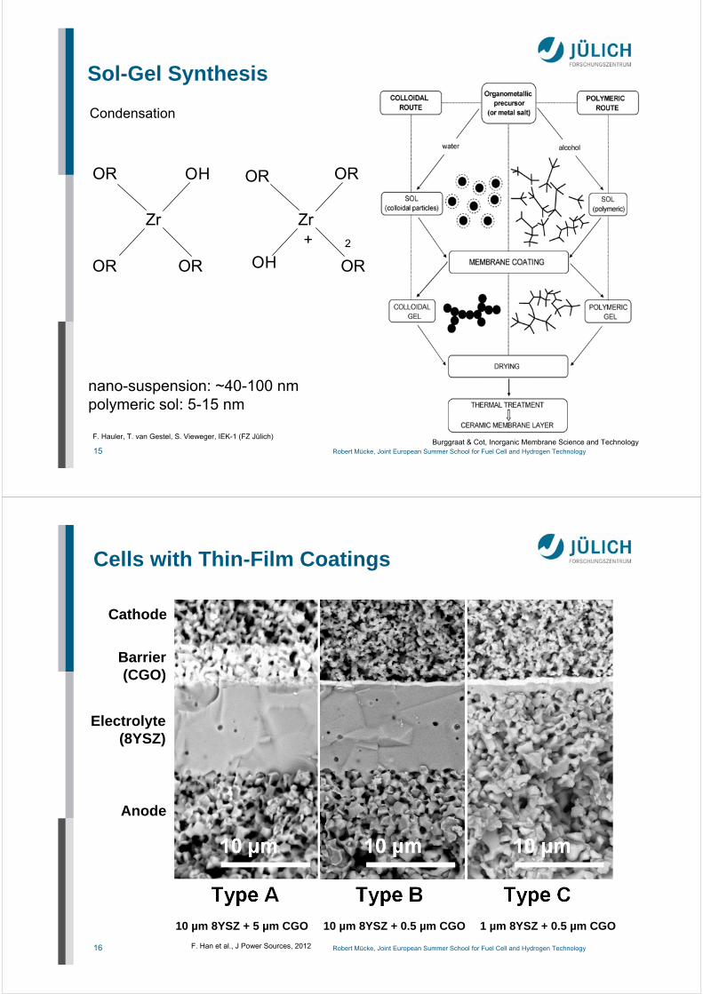
Sol-Gel Synthesis
OR = alkoxy group
Zr
OR
OR
O
OR
R
H O2H+
Hydrolysis
F. Hauler, T. van Gestel, S. Vieweger, IEK-1 (FZ Jülich)Burggraat & Cot, Inorganic Membrane Science and Technology
nano-suspension: ~40-100 nmpolymeric sol: 5-15 nm
15 Robert Mücke, Joint European Summer School for Fuel Cell and Hydrogen Technology
Sol-Gel Synthesis
nano-suspension: ~40-100 nmpolymeric sol: 5-15 nm
Zr
OR
OR
O
OR
H
Zr
OR
OROH
OR
2+
Condensation
F. Hauler, T. van Gestel, S. Vieweger, IEK-1 (FZ Jülich)Burggraat & Cot, Inorganic Membrane Science and Technology
16 Robert Mücke, Joint European Summer School for Fuel Cell and Hydrogen Technology
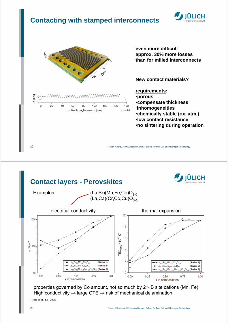
properties governed by Co amount, not so much by 2nd B site cations (Mn, Fe)High conductivity → large CTE → risk of mechanical delamination
27 Robert Mücke, Joint European Summer School for Fuel Cell and Hydrogen Technology
Contact layers - Perovskites
Tietz et al., Mater. Sci. Eng. B 150 (2008), 135-140
Formation of interface reaction zone
1: formation of Cr2O3 layer2: Cr2O3 (Cr,Mn)3O4 double layer
released Cr → CaCrO4dense layer of decomposed perovskites ontop of protective layer
3: Mn depletion in protective layergrow of CaCrO4, Ca free perovskite
4: further grow of scales
contact layer
protective layer
interconnect
LaMnCoCu basedlayers:Cu depletion other timeno further problemswith dense MCF protective layers(Cr barrier)
28 Robert Mücke, Joint European Summer School for Fuel Cell and Hydrogen Technology
3. Long Term Stability
29 Robert Mücke, Joint European Summer School for Fuel Cell and Hydrogen Technology
single repeating unit
interconnect
interconnect
oxide scale
Cr protection layer
cathode contact layer
MEA
anode contact
sealing
oxide scale
‘‘internal causes‘‘ = interactions / changes within the stack components
*N.H.Menzler et al. Ceram.Eng.Sci.Proc. 2008
Sources of Degration
30 Robert Mücke, Joint European Summer School for Fuel Cell and Hydrogen Technology
Cell Degradation due to Presence ofInterconnect Steel (Cr poisoning)
temperature: 800 °C
current density: 0.30 A/cm²fuel: H2 (1.0 l/min) + 3% H2Ooxidant: air (1.0 l/min)
Time [h]
Cel
l vo
ltag
e [
V]
31 Robert Mücke, Joint European Summer School for Fuel Cell and Hydrogen Technology
Meachnisms of Cr-Poisoning
LSM cathodesreaction at electrolyte interface(1) blockage of tri phase boundaries (see below) or (2) formation o Cr2O3+ (Cr,Mn)3O4insulating layer between cathode and electrolyte
Cr
Sr
Cr
LSCF cathodesvapor phase transport and
reaction at cathode surface
Cathode degradation currently dominant in cells
F. Tietz, FZJ
32 Robert Mücke, Joint European Summer School for Fuel Cell and Hydrogen Technology
Longest running planar SOFC stack so far short-stacks F1002-95 and 97
current density: 500 mA/cm²
700°C
700°C
failure of temperature
control
only failure causing any lossof power to a cell (or stack) (thus far)
failure of electronic
load
with WPS-protective layerLSCF-cathode
L. Blum et al., 10th European SOFC Forum Lucerne 2012, A1205
33 Robert Mücke, Joint European Summer School for Fuel Cell and Hydrogen Technology
Average cell voltages as function of date for short-stacks F1002-95 and 97
current density: 500 mA/cm²
700°C43,867 h
17,660 h
700°C
16 mV/kh 6 mV/kh
Post test analysis: revealed only small alteration and interaction.
# glass microstructure showed no phase changes# cell microstructure appeared to be only slightly modified# metallic parts out of Crofer22APU showed some
dot-like corrosion, but in general exhibited good bondingoxide layers of micrometres thickness
10 mV/kh
Mean voltagedegradation:1%V/kh
6 mV/kh
with WPS-protective layerLSCF-cathode
10 mV/kh
L. Blum et al., 10th European SOFC Forum Lucerne 2012, A1205
34 Robert Mücke, Joint European Summer School for Fuel Cell and Hydrogen Technology
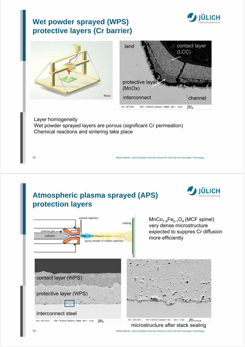
MnCo1.9Fe0.1O4 (MCF spinel)very dense microstructureexpected to suppres Cr diffusionmore efficiently
contact layer (WPS)
protective layer (WPS)
Interconnect steel
microstructure after stack sealing
37 Robert Mücke, Joint European Summer School for Fuel Cell and Hydrogen Technology
Average cell voltages as function of date for short-stacks F10
700°C
800°C
700°C
1%V/kh
0.3%V/kh
0.1-0.2%V/kh
L. Blum et al., 10th European SOFC Forum Lucerne 2012, A1205
H2 fuel
38 Robert Mücke, Joint European Summer School for Fuel Cell and Hydrogen Technology
Operation behavior as function of time for stack F’’’2018-07 (real fuels)
Mean voltagedegradation:
0.3%V/kh
2.6 kW
CH4: 4,935 h
L. Blum et al., 10th European SOFC Forum Lucerne 2012, A1205
39 Robert Mücke, Joint European Summer School for Fuel Cell and Hydrogen Technology
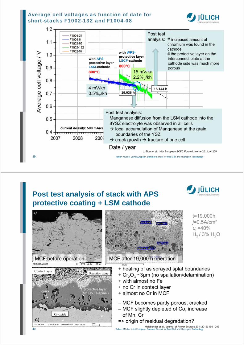
current density: 500 mA/cm²
Average cell voltages as function of date for short-stacks F1002-132 and F1004-08
4 mV/kh0.5%V/kh
with APS-protective layerLSM-cathode
19,036 h
800°C
with WPS-protective layerLSCF-cathode
15,144 h
800°C
Post test analysis: Manganese diffusion from the LSM cathode into the 8YSZ electrolyte was observed in all cells local accumulation of Manganese at the grain
boundaries of the YSZ crack growth fracture of one cell
15 mV/kh2.2%V/kh
Post test analysis: # increased amount of
chromium was found in the cathode # the protective layer on the interconnect plate at the cathode side was much more porous
L. Blum et al., 10th European SOFC Forum Lucerne 2011, A1205
40 Robert Mücke, Joint European Summer School for Fuel Cell and Hydrogen Technology
Post test analysis of stack with APS protective coating + LSM cathode
Malzbender et al., Journal of Power Sources 201 (2012) 196– 203
c)
MCF before operation MCF after 19,000 h operation
+ healing of as sprayed splat boundaries+ Cr2O3 ~3µm (no spallation/delamination)+ with almost no Fe+ no Cr in contact layer+ almost no Cr in MCF
41 Robert Mücke, Joint European Summer School for Fuel Cell and Hydrogen Technology
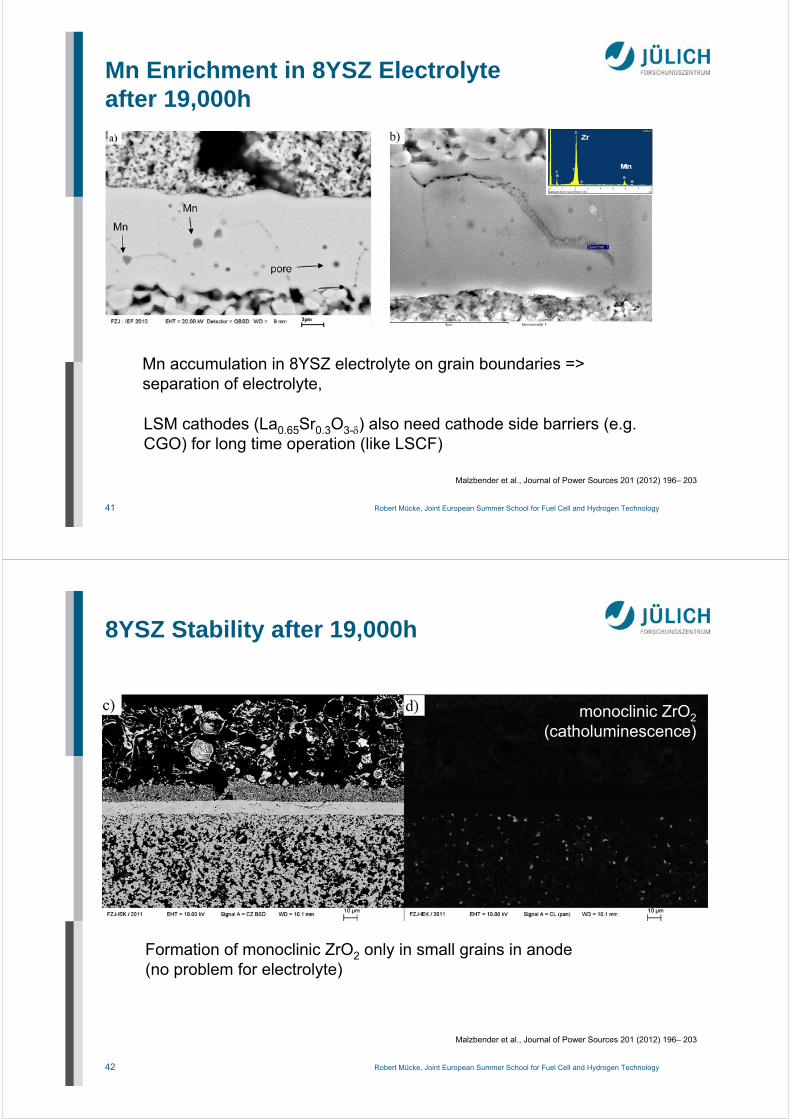
Mn Enrichment in 8YSZ Electrolyteafter 19,000h
Malzbender et al., Journal of Power Sources 201 (2012) 196– 203
Mn accumulation in 8YSZ electrolyte on grain boundaries => separation of electrolyte,
LSM cathodes (La0.65Sr0.3O3-) also need cathode side barriers (e.g. CGO) for long time operation (like LSCF)
42 Robert Mücke, Joint European Summer School for Fuel Cell and Hydrogen Technology
8YSZ Stability after 19,000h
monoclinic ZrO2(catholuminescence)
Formation of monoclinic ZrO2 only in small grains in anode(no problem for electrolyte)
Malzbender et al., Journal of Power Sources 201 (2012) 196– 203
43 Robert Mücke, Joint European Summer School for Fuel Cell and Hydrogen Technology
Ni/interconnect reaction
Ni mesh
Malzbender et al., Journal of Power Sources 201 (2012) 196– 203
Welded interfaces of Ni mesh and interconnect (Crofer 22APU)
austenitisation of steel (large CTE, faster corrosion)up-to now no limitation, could change, if long-term operation and therm+redox cycles are combined
44 Robert Mücke, Joint European Summer School for Fuel Cell and Hydrogen Technology
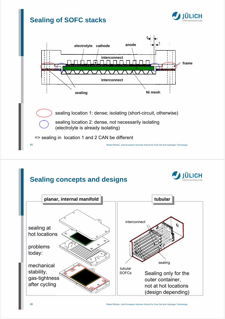
4. Stack Sealings
45 Robert Mücke, Joint European Summer School for Fuel Cell and Hydrogen Technology
sealing process / glass transitioncrystallization by change in CTE
CTE (electrolyte): 10-12 ppm/K
traditional/commercial glasses not suitable=> new developments started
~10 years agomaterials, interactions, manufacturing
49 Robert Mücke, Joint European Summer School for Fuel Cell and Hydrogen Technology
CTE ok, cristallization too fast
CTE too low, good adhesion
CTE too low
CTE ok, good adhesion
BaSi2
CaSi
Ba2Si3
X
Ca2BaSi3
CaOBaO
SiO2 glassy
partially glassy crystalline
+ 5 Al2O3
BaO CaO
SiO2
+ 0 Al2O
3
+ 10 Al2O
3
BaO CaO
SiO2
Glass, glass ceramicsSystem BaO - CaO - Al2O3 - SiO2
toughening with ceramic fibers/fillers(YSZ)
50 Robert Mücke, Joint European Summer School for Fuel Cell and Hydrogen Technology
x-y dispenser interconnectswith glass paste
stack assembly
Glass sealed stack
51 Robert Mücke, Joint European Summer School for Fuel Cell and Hydrogen Technology
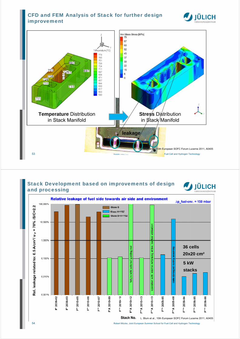
Stack Development based on improvements of design and processing
Improvement due to:
•Changes in
- design
- processing
- operation
•Combination of two
different glass sealing
materials for cell and
manifold
L. Blum et al., 10th European SOFC Forum Lucerne 2011, A0405
52 Robert Mücke, Joint European Summer School for Fuel Cell and Hydrogen Technology
Measured temperature distribution in a 1 kW stack (10 layers 20x20 cm²) from fuelin to fuelout (= airin) in case of different fuel gases and fuel utilization uF
L. Blum et al., 10th European SOFC Forum Lucerne 2011, A0405
53 Robert Mücke, Joint European Summer School for Fuel Cell and Hydrogen Technology
CFD and FEM Analysis of Stack for further design improvement
Temperature Distributionin Stack Manifold
Stress Distributionin Stack Manifold
leakage
L. Blum et al., 10th European SOFC Forum Lucerne 2011, A0405
54 Robert Mücke, Joint European Summer School for Fuel Cell and Hydrogen Technology
Stack Development based on improvements of design and processing
5 kW
stacks
L. Blum et al., 10th European SOFC Forum Lucerne 2011, A0405
36 cells
20x20 cm²
55 Robert Mücke, Joint European Summer School for Fuel Cell and Hydrogen Technology
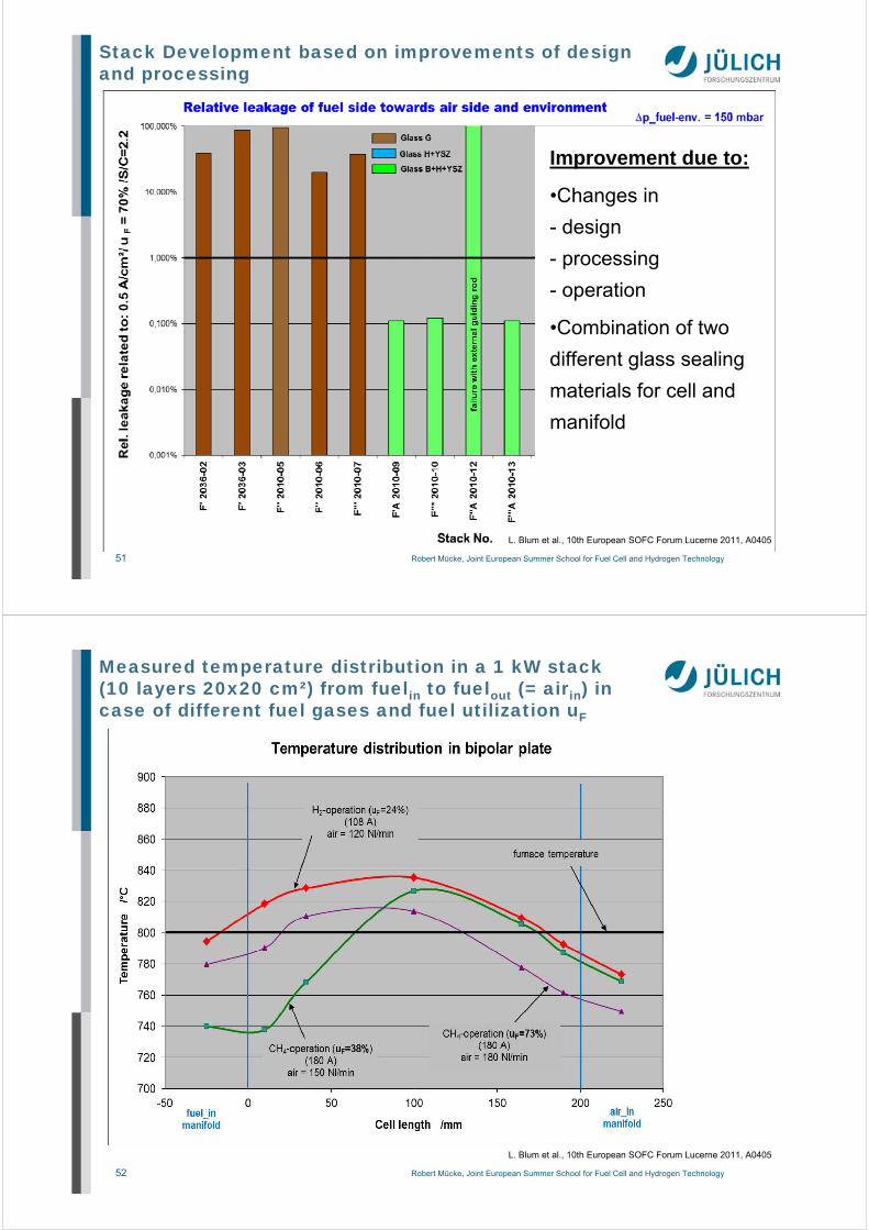
Application of Sealing of ASCs
dispenser screen printing
stamped, tape-cast foils
Kerafol, HC StarckD. Federmann, S. Groß, ZAT, FZ Jülich
characteristics:
dispenser: very flexible, slow, not scalablescreen printing: fast, flexible, special screens for large thicknesses (0.3 .. 0.5 mm)stencil printing: large thicknesses,
requires very flat supportstamped foils: basic shapes very accurate, shrinkage due to large amount of organics, limited material efficiency (recycling)
stencil printing
(metallic mask and blade)
56 Robert Mücke, Joint European Summer School for Fuel Cell and Hydrogen Technology
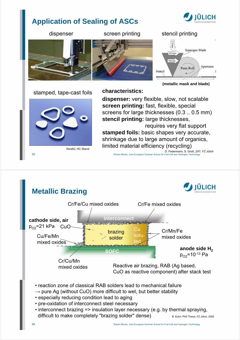
Metallic Brazing
SOFC
B. Kuhn, PhD Thesis, FZ Jülich, 2009
interconnect
Cr/Fe/Cu mixed oxides
CuO
Cr/Fe mixed oxides
Cr/Mn/Femixed oxidesCu/Fe/Mn
mixed oxides
Cr/Cu/Mnmixed oxides Reactive air brazing, RAB (Ag based,
CuO as reactive component) after stack test
Cusolu-ted
cathode side, airpO2=21 kPa
anode side H2pO2=10-13 Pa
brazingsolder
• reaction zone of classical RAB solders lead to mechanical failure→ pure Ag (without CuO) more difficult to wet, but better stability• especially reducing condition lead to aging• pre-oxidation of interconnect steel necessary• interconnect brazing => insulation layer necessary (e.g. by thermal spraying,difficult to make completely "brazing solder" dense)
57 Robert Mücke, Joint European Summer School for Fuel Cell and Hydrogen Technology
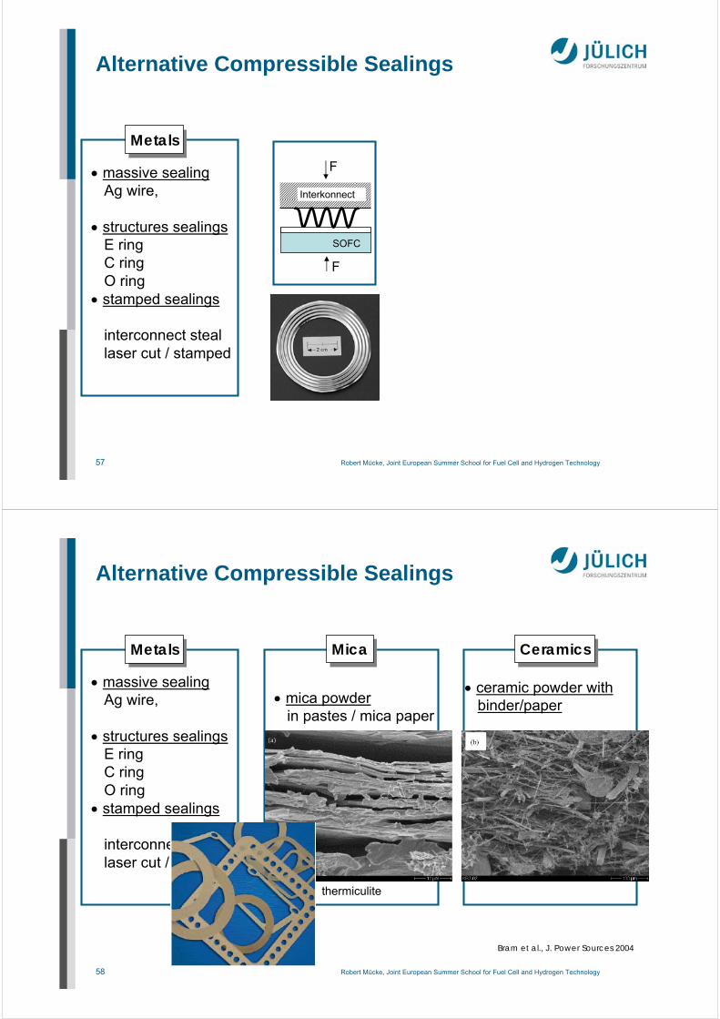
MetalsMetals
massive sealingAg wire,
structures sealingsE ringC ringO ring
stamped sealings
interconnect steallaser cut / stamped
SOFC
Interkonnect
F
F
Alternative Compressible Sealings
58 Robert Mücke, Joint European Summer School for Fuel Cell and Hydrogen Technology
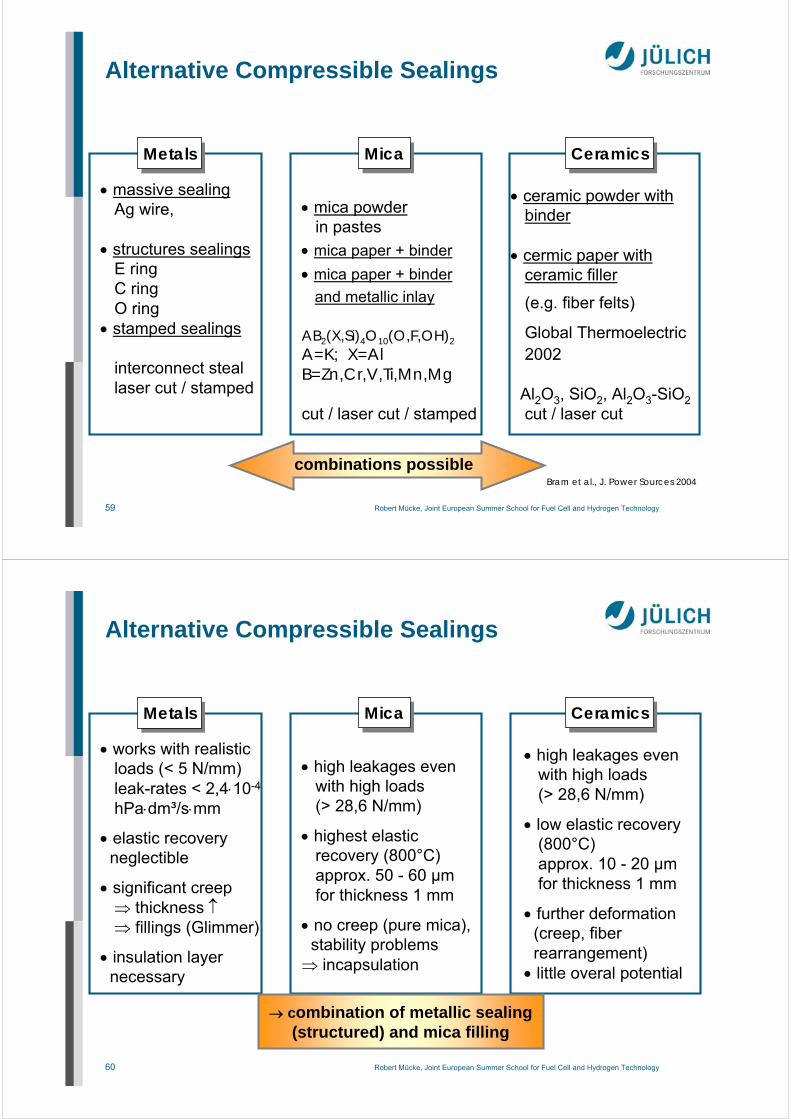
MetalsMetals
massive sealingAg wire,
structures sealingsE ringC ringO ring
stamped sealings
interconnect steallaser cut / stamped
mica powderin pastes / mica paper
ceramic powder withbinder/paper
MicaMica CeramicsCeramics
Alternative Compressible Sealings
Bram et al., J. Power Sources 2004
thermiculite
59 Robert Mücke, Joint European Summer School for Fuel Cell and Hydrogen Technology
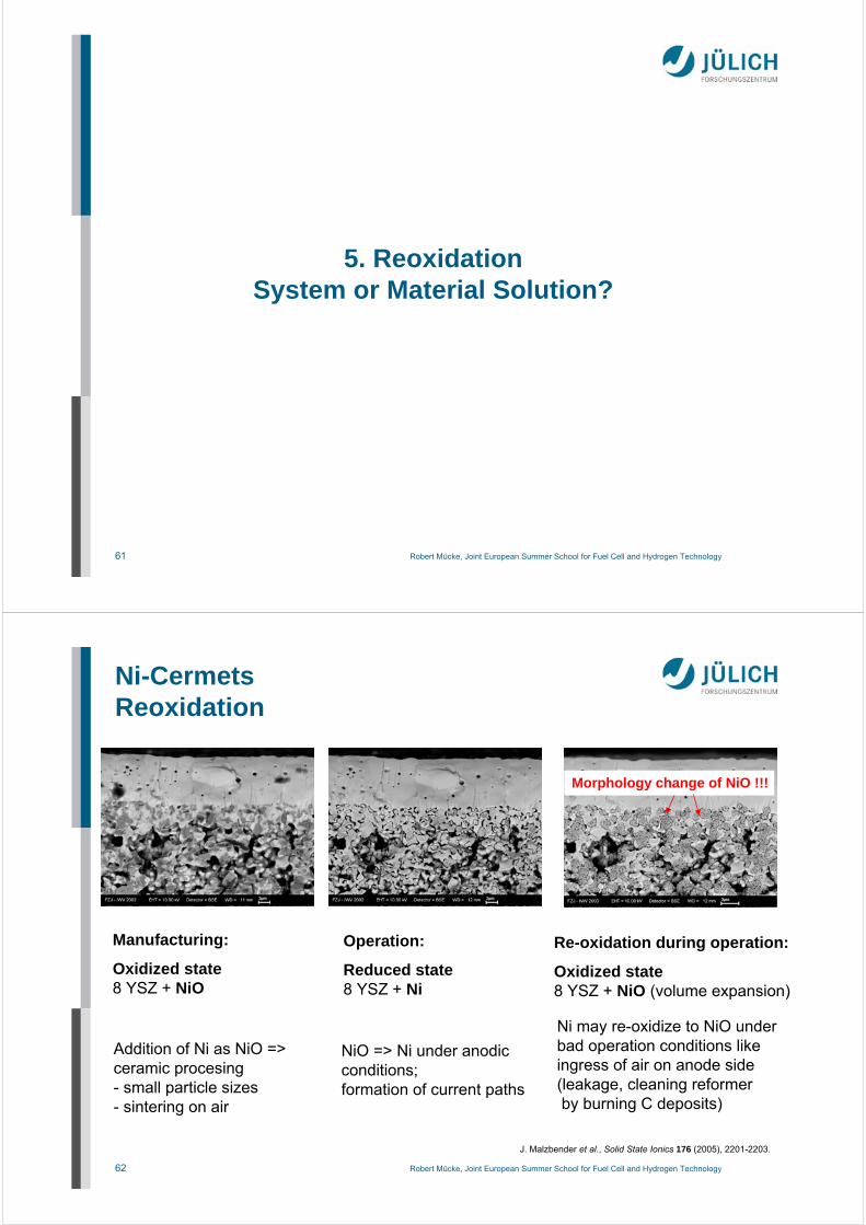
MetalsMetals
massive sealingAg wire,
structures sealingsE ringC ringO ring
stamped sealings
interconnect steallaser cut / stamped
mica powderin pastes
mica paper + binder
mica paper + binder
and metallic inlay
AB2(X,Si)4O10(O,F,OH)2
A=K; X=AlB=Zn,Cr,V,Ti,Mn,Mg
cut / laser cut / stamped
ceramic powder withbinder
cermic paper withceramic filler
(e.g. fiber felts)
Global Thermoelectric2002
Al2O3, SiO2, Al2O3-SiO2cut / laser cut
MicaMica CeramicsCeramics
combinations possible
Alternative Compressible Sealings
Bram et al., J. Power Sources 2004
60 Robert Mücke, Joint European Summer School for Fuel Cell and Hydrogen Technology
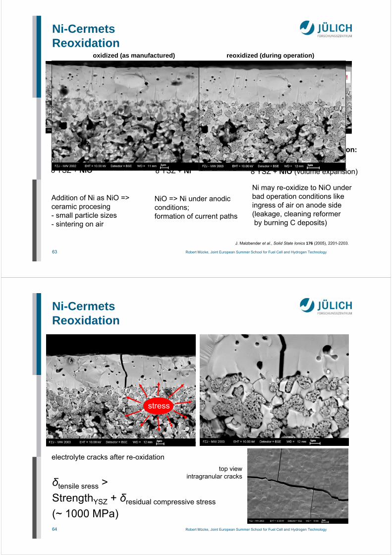
MetalsMetals
works with realisticloads (< 5 N/mm)leak-rates < 2,410-4
hPadm³/smm
elastic recoveryneglectible
significant creep thickness fillings (Glimmer)
insulation layernecessary
high leakages evenwith high loads(> 28,6 N/mm)
highest elasticrecovery (800°C) approx. 50 - 60 µm for thickness 1 mm
• acceptable conductivity• no reoxidation(but Ti valence change Ti3+ Ti4+)
• 3% NiO infiltrated for catalytic activity
69 Robert Mücke, Joint European Summer School for Fuel Cell and Hydrogen Technology
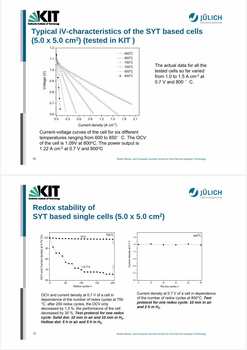
Typical iV-characteristics of the SYT based cells (5.0 x 5.0 cm2) (tested in KIT )
0.0 0.3 0.6 0.9 1.2 1.5 1.8 2.1
0.6
0.7
0.8
0.9
1.0
1.1
1.2
V
olta
ge
(V
)
Current density (A cm-2)
850oC
800oC
750oC
700oC
650oC
600oC
Current-voltage curves of the cell for six different temperatures ranging from 600 to 850°C. The OCV of the cell is 1.09V at 800oC. The power output is 1.22 A cm-2 at 0.7 V and 800oC
The actual data for all the tested cells so far varied from 1.0 to 1.5 A cm-2 at 0.7 V and 800 °C.
70 Robert Mücke, Joint European Summer School for Fuel Cell and Hydrogen Technology
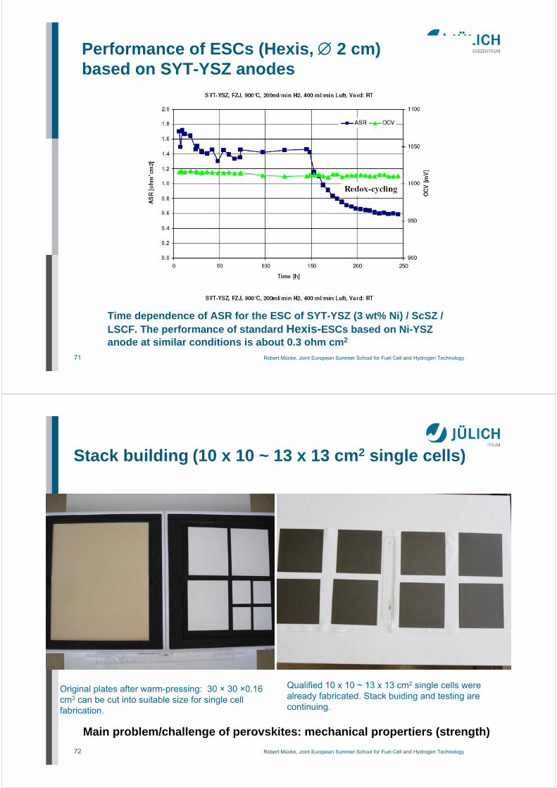
Redox stability of SYT based single cells (5.0 x 5.0 cm2)
0 10 20 30 40 500.0
0.3
0.6
0.9
1.2
1.5
1.8
Cur
ren
t de
nsi
ty a
t 0.7
V
Re-dox cycles n
800oC
Current density at 0.7 V of a cell in dependence of the number of redox cycles at 800°C. Test protocol for one redox cycle: 10 min in air and 2 h in H2.
0 50 100 150 20060
70
80
90
100750oC
OC
V a
nd C
urre
nt d
ensi
ty a
t 0.7
V (
%)
Redox cycles n
OCV
I (0.7V)
OCV and current density at 0.7 V of a cell in dependence of the number of redox cycles at 750 °C. after 200 redox cycles, the OCV only decreased by 1.3 %, the performance of the cell decreased by 35 %. Test protocol for one redoxcycle: Solid dot: 10 min in air and 10 min in H2. Hollow dot: 5 h in air and 5 h in H2.
71 Robert Mücke, Joint European Summer School for Fuel Cell and Hydrogen Technology
Performance of ESCs (Hexis, 2 cm)based on SYT-YSZ anodes
Time dependence of ASR for the ESC of SYT-YSZ (3 wt% Ni) / ScSZ / LSCF. The performance of standard Hexis-ESCs based on Ni-YSZanode at similar conditions is about 0.3 ohm cm2
72 Robert Mücke, Joint European Summer School for Fuel Cell and Hydrogen Technology
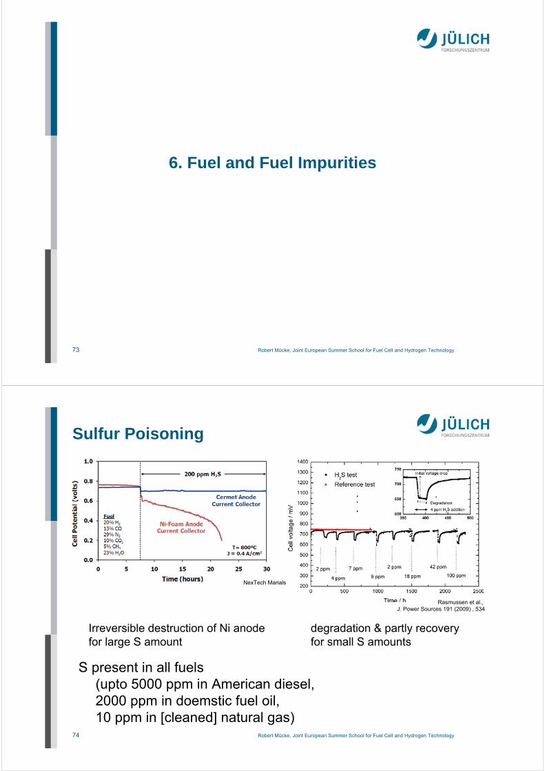
Stack building (10 x 10 ~ 13 x 13 cm2 single cells)
Original plates after warm-pressing: 30 × 30 ×0.16 cm3 can be cut into suitable size for single cellfabrication.
Qualified 10 x 10 ~ 13 x 13 cm2 single cells werealready fabricated. Stack buiding and testing arecontinuing.
Main problem/challenge of perovskites: mechanical propertiers (strength)
73 Robert Mücke, Joint European Summer School for Fuel Cell and Hydrogen Technology
6. Fuel and Fuel Impurities
74 Robert Mücke, Joint European Summer School for Fuel Cell and Hydrogen Technology
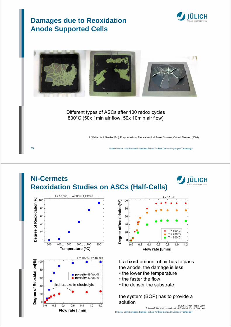
Sulfur Poisoning
S present in all fuels(upto 5000 ppm in American diesel, 2000 ppm in doemstic fuel oil, 10 ppm in [cleaned] natural gas)
Irreversible destruction of Ni anodefor large S amount
NexTech Marials
Rasmussen et al., J. Power Sources 191 (2009) , 534
degradation & partly recoveryfor small S amounts
75 Robert Mücke, Joint European Summer School for Fuel Cell and Hydrogen Technology
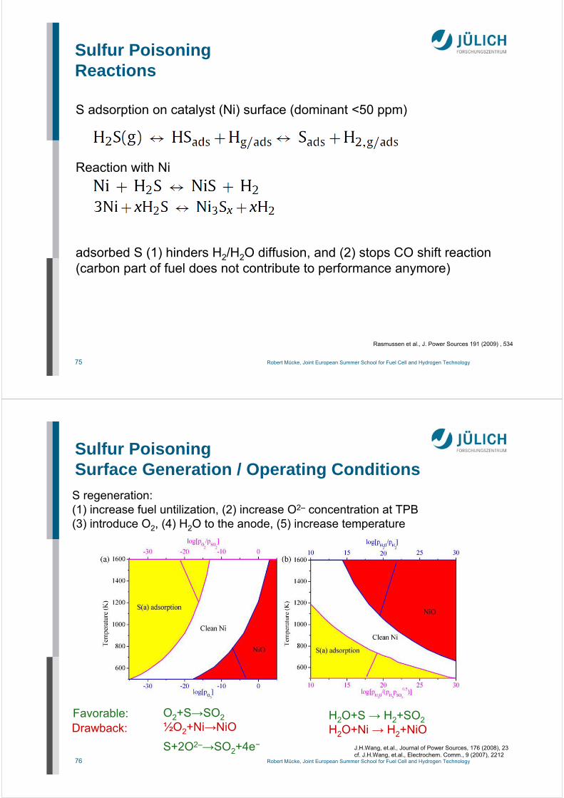
Sulfur PoisoningReactions
S adsorption on catalyst (Ni) surface (dominant <50 ppm)
Reaction with Ni
Rasmussen et al., J. Power Sources 191 (2009) , 534
adsorbed S (1) hinders H2/H2O diffusion, and (2) stops CO shift reaction(carbon part of fuel does not contribute to performance anymore)
76 Robert Mücke, Joint European Summer School for Fuel Cell and Hydrogen Technology
C filaments growinside Ni grains grains burst cell disintegrates
50x50mm
81 Robert Mücke, Joint European Summer School for Fuel Cell and Hydrogen Technology
7. Metal Supported Cells (MSC)
82 Robert Mücke, Joint European Summer School for Fuel Cell and Hydrogen Technology
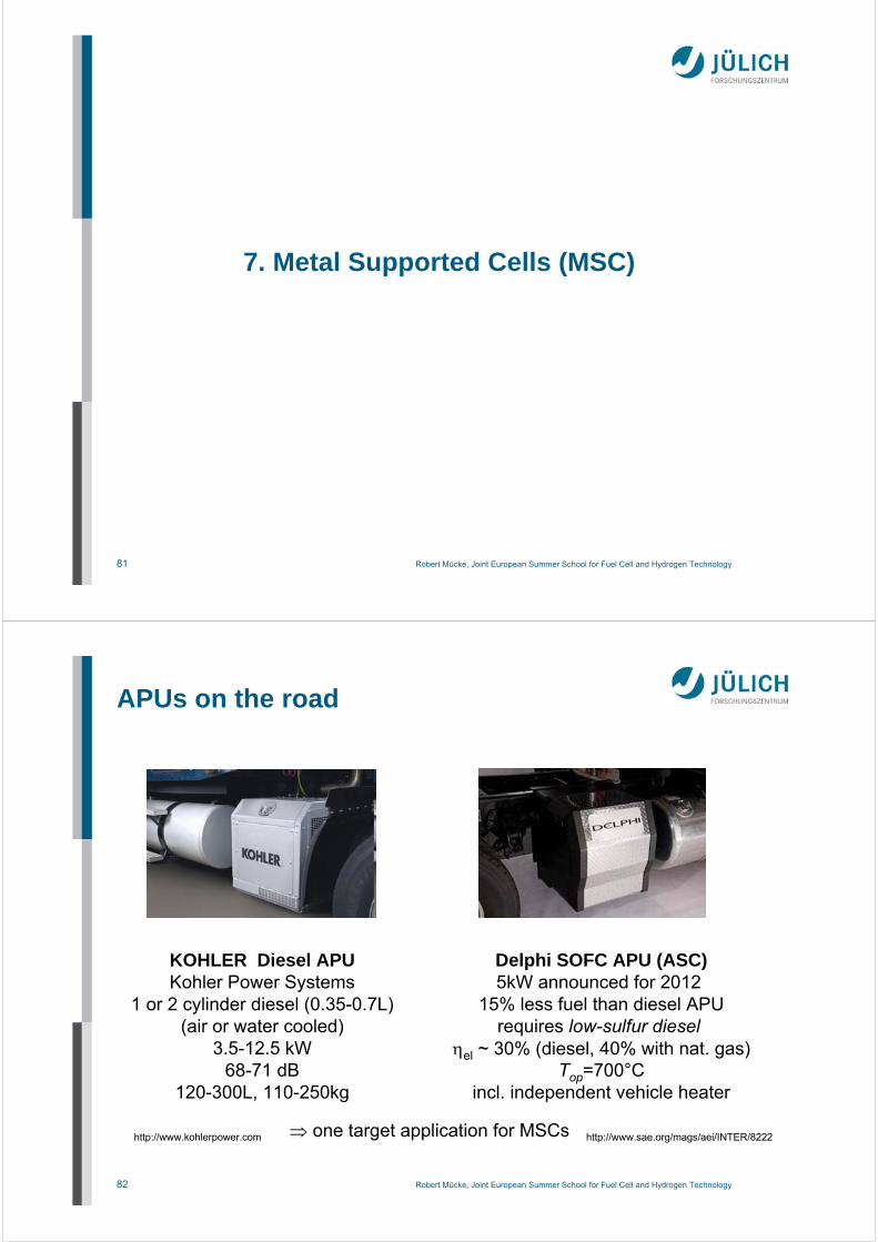
APUs on the road
KOHLER Diesel APUKohler Power Systems
1 or 2 cylinder diesel (0.35-0.7L)(air or water cooled)
3.5-12.5 kW68-71 dB
120-300L, 110-250kg
Delphi SOFC APU (ASC)5kW announced for 2012
15% less fuel than diesel APUrequires low-sulfur diesel
el ~ 30% (diesel, 40% with nat. gas)Top=700°C
incl. independent vehicle heater
http://www.sae.org/mags/aei/INTER/8222http://www.kohlerpower.com one target application for MSCs
83 Robert Mücke, Joint European Summer School for Fuel Cell and Hydrogen TechnologyDGM-Seminar, Werkstofffragen der Hochtemperatur-Brennstoffzelle (SOFC) . 83
Reduced material costs for the support compared to Ni/YSZ (anode support) or perovskites (cathode support)
Robustness against thermal cycling
Robustness against redox cycles
Robustness against mechanical stresses
Stack integration of cells via brazing or welding
High electronic conductivity
High thermal conductivity
Anode Support
Electrolyte
Cathode
AnodeElectrolyte Support
Cathode
Anode Cathode Support
Electrolyte
Anode
CathodeMetall Support
SOFC Development
Potential of Metal Supported Cells
84 Robert Mücke, Joint European Summer School for Fuel Cell and Hydrogen TechnologyDGM-Seminar, Werkstofffragen der Hochtemperatur-Brennstoffzelle (SOFC) . 84
Reduced material costs for the support compared to Ni/YSZ (anode support) or perovskites (cathode support)
Robustness against thermal cycling
Robustness against redox cycles
Robustness against mechanical stresses
Stack integration of cells via brazing or welding
High electronic conductivity
High thermal conductivity
Anode Support
Electrolyte
Cathode
AnodeElectrolyte Support
Cathode
Anode Cathode Support
Electrolyte
Anode
CathodeMetall Support
SOFC Development
Potential of Metal Supported Cells
Welded cell in cassette
85 Robert Mücke, Joint European Summer School for Fuel Cell and Hydrogen Technology
Materials for metal SOFC supports Requirements and available products
conductive oxide scale
appropriate CTE(electrolyte, anode:
10-13 ppm/K)
Cr2O3-formers(Ti add. for better adherence)
no Al2O3-formers
ferritic steels(with approx. 20-26% Cr)
no austenites
mechanical properties(not brittle, feasible for
stamping / welding)
ferritic steels, Ni-baseno Cr-based alloys
oxide dispersed strengthened(ODS, P/M),
laves phases (I/M),addition of Mo, Nb
creep stability / HT strength
(no creep at high temp.)
ITM (Plansee), P/MFe-26Cr-(Mo, Ti, Y2O3)
Crofer 22APU (ThyssenKrupp) Fe-22Cr-(Mn, Ti, La)
Crofer 22 H (ThyssenKrupp) Fe-22Cr-(W, Nb, Si)
Hastelloy X (Haynes)Ni-22Cr-Fe-Mo-Co-W
(but ~16 ppm/K)
ZMG 232L (Hitachi Metals)Fe-22Cr-Ni-Mn-Si-Zr-La
Sanergy HT, 1C44Mo20 (Sandvik)
Fe-22Cr-(Mn-Mo-Nb-Ti)
Lab-steel (JFE Corp.)Fe-20Cr-Si-Mn-Nb-Mo-La
all materials already usedfor metallic interconnects
86 Robert Mücke, Joint European Summer School for Fuel Cell and Hydrogen Technology
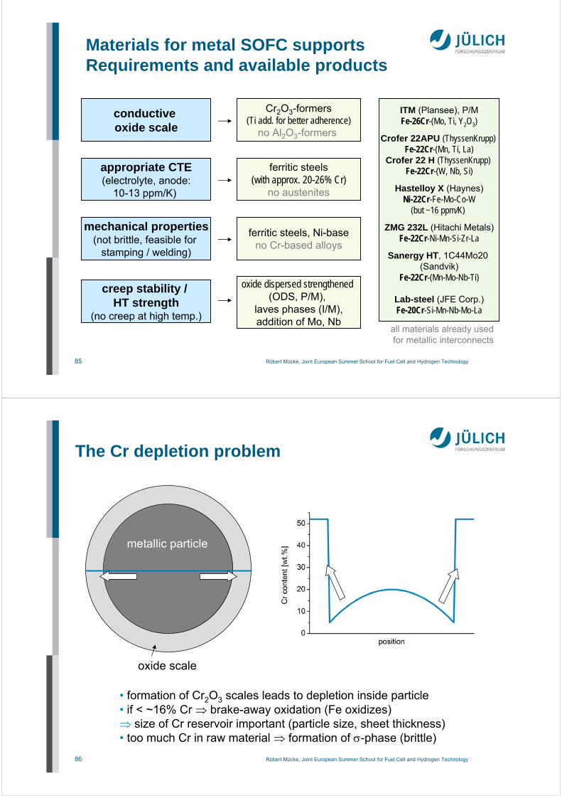
The Cr depletion problem
metallic particle
oxide scale
• formation of Cr2O3 scales leads to depletion inside particle• if < ~16% Cr brake-away oxidation (Fe oxidizes) size of Cr reservoir important (particle size, sheet thickness)• too much Cr in raw material formation of -phase (brittle)
87 Robert Mücke, Joint European Summer School for Fuel Cell and Hydrogen Technology
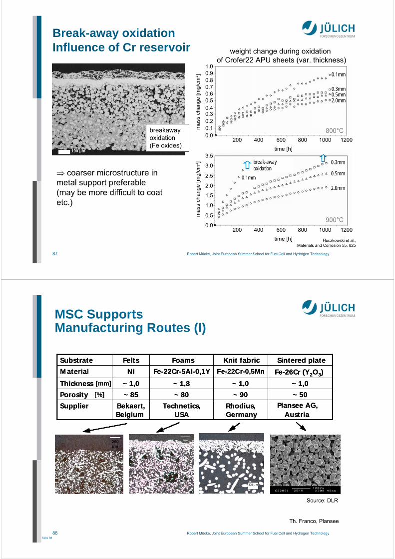
Break-away oxidationInfluence of Cr reservoir
200 400 600 800 1000 1200
time [h]
0.0
0.5
1.0
1.5
2.0
2.5
3.0
3.5
mas
s ch
ange
[mg/
cm²]
0.00.10.20.30.40.50.60.70.80.91.0
mas
s ch
ange
[mg/
cm²]
200 400 600 800 1000 1200
time [h]
900°C
800°C
2.0mm
0.5mm
0.3mm
0.1mm
weight change during oxidation of Crofer22 APU sheets (var. thickness)
break-away oxidation
2.0mm0.5mm0.3mm
0.1mm
Huczkowski et al., Materials and Corrosion 55, 825
coarser microstructure in metal support preferable(may be more difficult to coat etc.)
100 µm
breakawayoxidation(Fe oxides)
88 Robert Mücke, Joint European Summer School for Fuel Cell and Hydrogen TechnologySeite 88
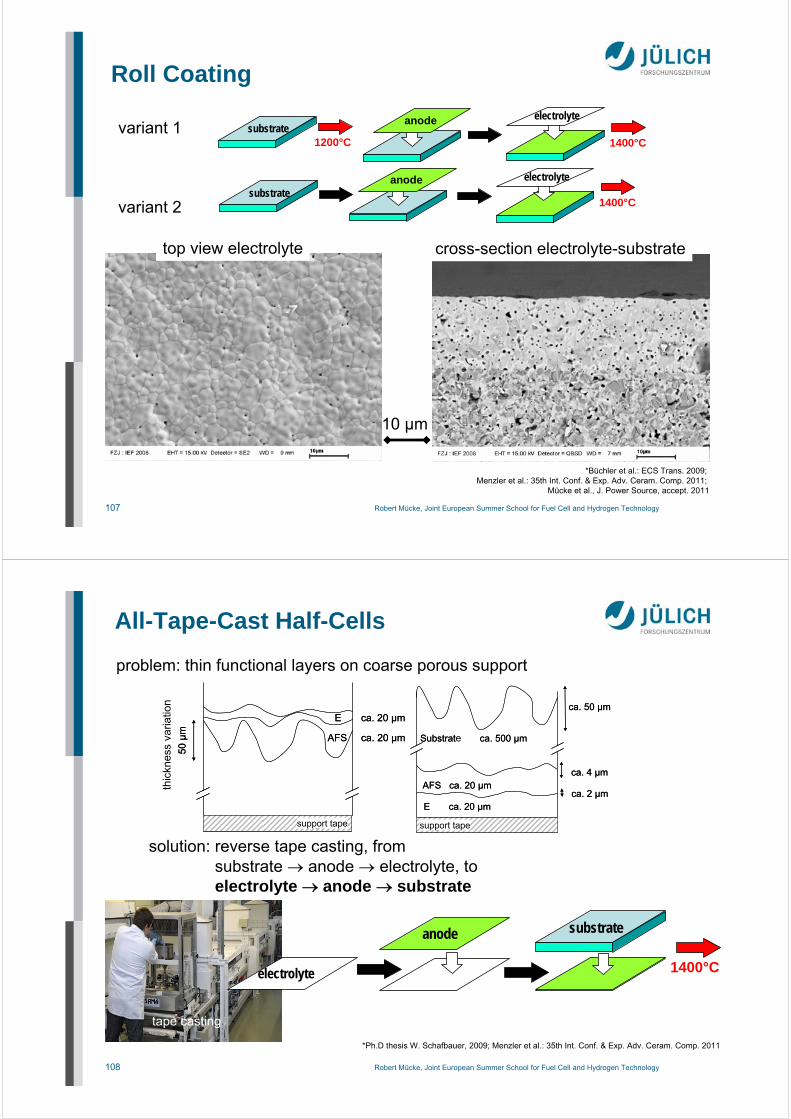
summary 2010:2 thermal treatments1 or 2 manufacturing techniques(all of them mass manufacturing)
Summary: Innovative Cell Manufacturing
111 Robert Mücke, Joint European Summer School for Fuel Cell and Hydrogen Technology
Summary
Bring SOFC to the people(real life applications)
long term stability(40,000-80,000h stationary,5,000-15,000h mobile appl.)
accelerated testing (requires understanding)
real field operation (sulfur, high uF,
combine loads/cycle), most test capacity
lower the costs(industrial manufacturing)
may allow cheap replaceable modules
Next generation SOFC
new materials, e.g. ceramic anode,
metallic substrate
thin film technologies400°C SOFC
(new electrodes)
prove feasability formanufacturing and
operation (a button cellis not enough)
(but keepthe
runningsystem)
112 Robert Mücke, Joint European Summer School for Fuel Cell and Hydrogen Technology
Acknowledgements
Special thanks for graphics and providing results are due to
Dr. Thomas Fraco (Plansee SE)Prof. E. Ivers-Tiffée • Dr. André Weber (IWE Karlsruhe)Dr. Martin Bram • Dr. Manuel Ettler • D. Federmann •Dr. Izaak C. Finke • Dr. S.M. Groß • Dr. V.A.C. Haanappel •Dr. L.G.J. de Haart • Dr. Feng Han • Dr. Natividat Jordan-Escalona •Dr. Norbert H. Menzler • Dr. Wolfgang Schafbauer •Dr. Frank Tietz • Dr. Sven Uhlenbruck • Dr. Tim Van Gestel •Prof. Robert Vaßen • Sebastian Vieweger(all FZ Jülich)
The former fuel cell project team under Dr. Robert Steinberger-Wilckens.The SOFC group of IEK-1 in Jülich under Dr. H.-P. Buchkremer (and formerlyProf. D. Stöver).