American Institute of Aeronautics and Astronautics 1 Current Status of the Nitrogen Oxygen Recharge System Brandon Dick 1 The Boeing Company, Huntsville, Alabama, 35803 This paper presents an overview of the Nitrogen Oxygen Recharge System (NORS) to date and the current development status of the system. NORS is an element of the International Space Station (ISS) Environmental Control and Life Support Systems (ECLSS) used to resupply the ISS with Nitrogen and Oxygen following the impending retirement of the Space Shuttle. The paper will discuss why NASA is developing NORS, including a summary of other concepts considered, and other related concepts currently being developed by NASA. The current system architecture will be described, along with a summary of the current design of the NORS. The overall programmatic schedule of the NORS in the context of the upcoming shuttle retirement and future launch vehicle development will also be presented. Finally, the paper will examine the significant technical challenges encountered during the requirements and preliminary design phase of NORS development. A key challenge to the development of NORS is the international shipment - and associated regulations - of pressurized Oxygen, which is necessary due to the use of launch vehicles based in Japan and French Guiana to send NORS gasses to the ISS. The storage and use of relatively large quantities of high pressure (41,000 kPa) Oxygen and Nitrogen within the ISS, which is unprecedented both on the ISS and other space vehicles, has had a significant impact on the design and architecture of the system. The high pressure of the system also poses unique thermal considerations, which has led to the development of a heater system for thermal conditioning of high pressure gas to avoid thermal impacts on downstream hardware. The on-orbit envelope allocated to the NORS has changed (gotten smaller) and has impacted both the design and architecture of the system. Finally, the balance of safety considerations associated with these high pressure gasses, particularly high pressure Oxygen, with the functionality of the system has profoundly impacted the form of the system and will be discussed. I. Introduction he final Space Shuttle missions, all missions to the International Space Station (ISS), are scheduled to be completed this year. The Space Shuttle is the primary vehicle for resupply of the ISS, including food and clothing for the crew of the station, spare parts for maintenance, and ferrying of scientific experiments to and from the station. The Space Shuttle also supplies the bulk of the pressurized Oxygen and Nitrogen for use on the ISS. Pressurized Oxygen and Nitrogen are used on the ISS for a variety of purposes. Nitrogen is of course the primary component of the atmosphere on-board the station. Leakage overboard accounts for a significant usage of Nitrogen. Additionally, the ISS program is mandated to maintain a supply of Nitrogen sufficient to repressurize a module (e.g. the US Lab - Destiny - or the Japanese Experiment Module (JEM) - Kibo) in the event of a depressurization. Nitrogen is also used in experiments, and as a source to pressurize both the internal and external Thermal Control Systems on the ISS. Oxygen stores are used to fulfil crew metabolic requirements in the event of failure of the Elektron or the Oxygen Generator Assembly (OGA). Pressurized Oxygen is also used in the event of a medical emergency. Finally pressurized Oxygen is used by the crew of the ISS prior to Extra-Vehicular Activity (EVA) to purge Nitrogen from their bodies and also during the EVA in the EVA Mobility Unit (EMU). Stores of Oxygen and Nitrogen are maintained on the ISS in two locations. The first is in the High Pressure Gas Tanks (HPGTs) located around the Airlock module. There are currently three Oxygen HPGTs and two Nitrogen HPGTs. A final HPGT will be delivered on STS-134, but will be maintained as an on-orbit spare. Nitrogen is also stored in the external Thermal Control System in the Nitrogen Tank Assemblies, one each of which is located on the P1 and S1 trusses. T https://ntrs.nasa.gov/search.jsp?R=20110012004 2020-03-08T22:28:15+00:00Z
Transcript
American Institute of Aeronautics and Astronautics
1
Current Status of the Nitrogen Oxygen Recharge System
Brandon Dick1 The Boeing Company, Huntsville, Alabama, 35803
This paper presents an overview of the Nitrogen Oxygen Recharge System (NORS) to date and the current development status of the system. NORS is an element of the International Space Station (ISS) Environmental Control and Life Support Systems (ECLSS) used to resupply the ISS with Nitrogen and Oxygen following the impending retirement of the Space Shuttle. The paper will discuss why NASA is developing NORS, including a summary of other concepts considered, and other related concepts currently being developed by NASA. The current system architecture will be described, along with a summary of the current design of the NORS. The overall programmatic schedule of the NORS in the context of the upcoming shuttle retirement and future launch vehicle development will also be presented. Finally, the paper will examine the significant technical challenges encountered during the requirements and preliminary design phase of NORS development. A key challenge to the development of NORS is the international shipment - and associated regulations - of pressurized Oxygen, which is necessary due to the use of launch vehicles based in Japan and French Guiana to send NORS gasses to the ISS. The storage and use of relatively large quantities of high pressure (41,000 kPa) Oxygen and Nitrogen within the ISS, which is unprecedented both on the ISS and other space vehicles, has had a significant impact on the design and architecture of the system. The high pressure of the system also poses unique thermal considerations, which has led to the development of a heater system for thermal conditioning of high pressure gas to avoid thermal impacts on downstream hardware. The on-orbit envelope allocated to the NORS has changed (gotten smaller) and has impacted both the design and architecture of the system. Finally, the balance of safety considerations associated with these high pressure gasses, particularly high pressure Oxygen, with the functionality of the system has profoundly impacted the form of the system and will be discussed.
I. Introduction he final Space Shuttle missions, all missions to the International Space Station (ISS), are scheduled to be completed this year. The Space Shuttle is the primary vehicle for resupply of the ISS, including food and
clothing for the crew of the station, spare parts for maintenance, and ferrying of scientific experiments to and from the station. The Space Shuttle also supplies the bulk of the pressurized Oxygen and Nitrogen for use on the ISS.
Pressurized Oxygen and Nitrogen are used on the ISS for a variety of purposes. Nitrogen is of course the primary component of the atmosphere on-board the station. Leakage overboard accounts for a significant usage of Nitrogen. Additionally, the ISS program is mandated to maintain a supply of Nitrogen sufficient to repressurize a module (e.g. the US Lab - Destiny - or the Japanese Experiment Module (JEM) - Kibo) in the event of a depressurization. Nitrogen is also used in experiments, and as a source to pressurize both the internal and external Thermal Control Systems on the ISS. Oxygen stores are used to fulfil crew metabolic requirements in the event of failure of the Elektron or the Oxygen Generator Assembly (OGA). Pressurized Oxygen is also used in the event of a medical emergency. Finally pressurized Oxygen is used by the crew of the ISS prior to Extra-Vehicular Activity (EVA) to purge Nitrogen from their bodies and also during the EVA in the EVA Mobility Unit (EMU).
Stores of Oxygen and Nitrogen are maintained on the ISS in two locations. The first is in the High Pressure Gas Tanks (HPGTs) located around the Airlock module. There are currently three Oxygen HPGTs and two Nitrogen HPGTs. A final HPGT will be delivered on STS-134, but will be maintained as an on-orbit spare. Nitrogen is also stored in the external Thermal Control System in the Nitrogen Tank Assemblies, one each of which is located on the P1 and S1 trusses.
American Institute of Aeronautics and Astronautics
2
The National Aeronautics and Space Administration (NASA) has anticipated the retirement of the Space Shuttle since the Columbia disaster in 2003. With the final flights of the orbiter scheduled for this year, the primary vehicle for supplying the ISS with Oxygen and Nitrogen will no longer be available.
The Nitrogen Oxygen Recharge System (NORS) will be used to continue to resupply the ISS with pressurized Oxygen and Nitrogen following Shuttle retirement..
II. Conceptual Design and Architecture The NORS consists of five primary parts: the Ground Fill Assembly (GFA), the Recharge Tank Assembly
(RTA), the Internal Fill Assembly (IFA), the External Fill Assembly (EFA), and the Airlock Installation Kit (AIK). The Recharge Tank Assembly (RTA) is the vessel that will be used to transport pressurized Oxygen and Nitrogen to the ISS. The Internal Fill Assemblies (IFA) regulate the pressure of the gas from the RTA below the MDP of the Airlock and Portable Breathing Apparatus (PBA). Some of the NORS hardware is permanently installed in the Airlock module. This hardware is called the Airlock Installation Kit (AIK). The External Fill Assembly (EFA) is used to resupply the Nitrogen Tank Assembly (NTA) with Nitrogen. Each of these items will be described in more detail in section 3. Figure 1 shows the general architecture of NORS.
Figure 1. NORS general architecture.
GFA RTA IFA
ERA
O2/N2
N2
Existing ISS Interfaces
Ground Support
Equipment
Earth Transport
and Launch Vehicles
O2/N2
Airlock O2/N2 System
NTAN2
O2/N2
Permanent New
Hardware
AIKO2/N2
Fill Assemblies
CASEO
O2
PBAO2
A. Recharge Tank Assembly (RTA) The Recharge Tank Assembly (RTA) is the vessel that will be used to transport pressurized Oxygen and
Nitrogen to the ISS. The RTA consists of three parts: a composite overwrap pressure vessel (COPV), the RTA Valve Assembly (RVA), and a high pressure Quick Disconnect (QD). The RTA will be filled with either Oxygen or Nitrogen at a pressure of 41.4 MPa (6000 psi). It will be designed with a Maximum Design Pressure of 48.3 MPa (7000 psi). The assembly will be filled at the Kennedy Space Center (KSC) and shipped will fully pressurized to the various launch sites. Figure 2 shows the general design concept for the RTA.
American Institute of Aeronautics and Astronautics
3
Figure 2. RTA design concept.
RTA VALVE ASSY
QD
COPV
1. Composite Overwrap Pressure Vessel (COPV) The COPV is being designed and manufactured by Alliant Techsystems Inc. (ATK). The COPV is designed to
hold approximately 27.2 kg (60 lbm) Nitrogen and 36.3 kg (80 lbm) of Oxygen. The tank has a single port for filling and emptying, but has two bosses for handling purposes. To facilitate a more streamlined transportation process, the tank is being designed and certified to ISO 11119. This standard requires that the tank be designed and tested for rough handling conditions, although the tank will nominally be treated very delicately. In addition to making the tank easier to transport, designing to this standard ensures that the tank is very robust. ATK is currently in the start of development efforts for the tank.
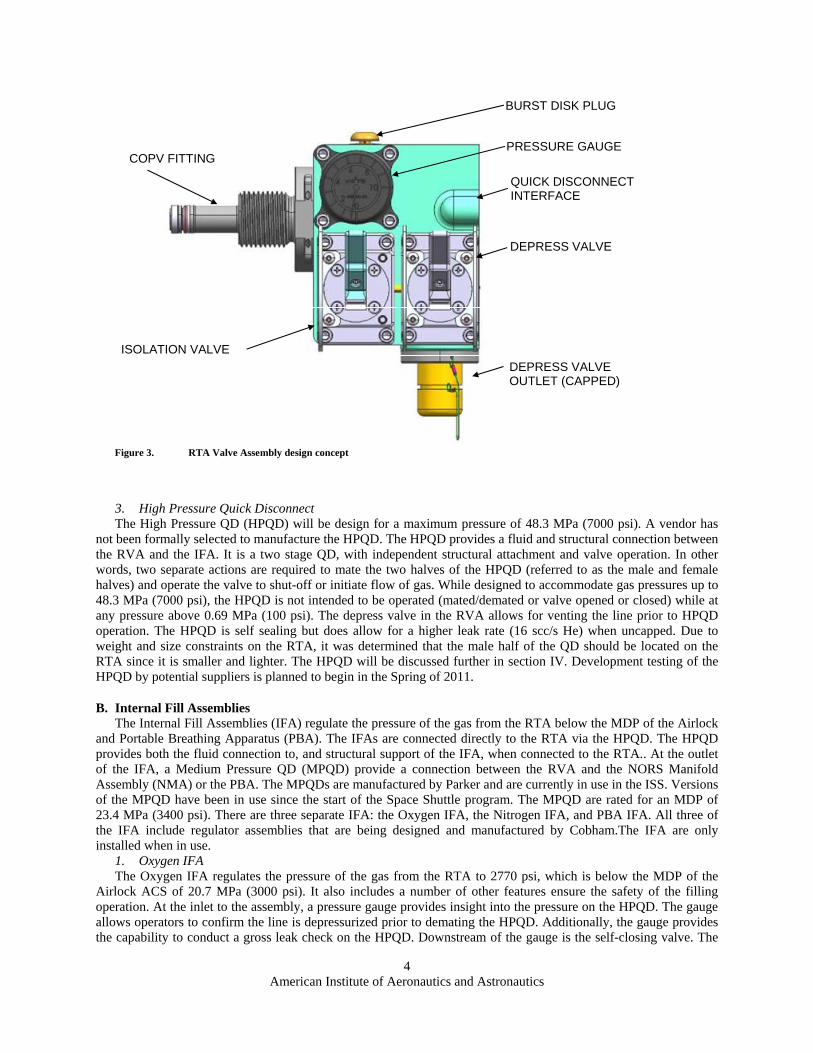
2. RTA Valve Assembly (RVA) The RVA is being designed and manufactured by Cobham. The RVA isolates the flow of gas from the COPV
and provides a connection to the Internal Fill Assembly (IFA) thought the QD. To allow easier QD operation, the RVA includes a includes a line depress valve. Additionally, the RVA includes a pressure gauge to provide insight into the quantity of gas contained in the COPV and a burst disk. The burst disk is required by the Department of Transportation (DOT) for cylinders of Oxygen being transported on aircraft in the United States. While designed for unique service (high pressure Oxygen), the RVA valve mechanisms have a high degree of commonality with the existing Oxygen and Nitrogen manual valves in the Airlock, also design by Cobham. Development testing of the RVA is planned to begin in the Spring of 2011. Figure 3 shows the RTA Valve Assembly design concept.
American Institute of Aeronautics and Astronautics
4
Figure 3. RTA Valve Assembly design concept
BURST DISK PLUG
PRESSURE GAUGE
QUICK DISCONNECT INTERFACE
DEPRESS VALVE
DEPRESS VALVE OUTLET (CAPPED)
ISOLATION VALVE
COPV FITTING
3. High Pressure Quick Disconnect The High Pressure QD (HPQD) will be design for a maximum pressure of 48.3 MPa (7000 psi). A vendor has
not been formally selected to manufacture the HPQD. The HPQD provides a fluid and structural connection between the RVA and the IFA. It is a two stage QD, with independent structural attachment and valve operation. In other words, two separate actions are required to mate the two halves of the HPQD (referred to as the male and female halves) and operate the valve to shut-off or initiate flow of gas. While designed to accommodate gas pressures up to 48.3 MPa (7000 psi), the HPQD is not intended to be operated (mated/demated or valve opened or closed) while at any pressure above 0.69 MPa (100 psi). The depress valve in the RVA allows for venting the line prior to HPQD operation. The HPQD is self sealing but does allow for a higher leak rate (16 scc/s He) when uncapped. Due to weight and size constraints on the RTA, it was determined that the male half of the QD should be located on the RTA since it is smaller and lighter. The HPQD will be discussed further in section IV. Development testing of the HPQD by potential suppliers is planned to begin in the Spring of 2011.
B. Internal Fill Assemblies The Internal Fill Assemblies (IFA) regulate the pressure of the gas from the RTA below the MDP of the Airlock
and Portable Breathing Apparatus (PBA). The IFAs are connected directly to the RTA via the HPQD. The HPQD provides both the fluid connection to, and structural support of the IFA, when connected to the RTA.. At the outlet of the IFA, a Medium Pressure QD (MPQD) provide a connection between the RVA and the NORS Manifold Assembly (NMA) or the PBA. The MPQDs are manufactured by Parker and are currently in use in the ISS. Versions of the MPQD have been in use since the start of the Space Shuttle program. The MPQD are rated for an MDP of 23.4 MPa (3400 psi). There are three separate IFA: the Oxygen IFA, the Nitrogen IFA, and PBA IFA. All three of the IFA include regulator assemblies that are being designed and manufactured by Cobham.The IFA are only installed when in use.
1. Oxygen IFA The Oxygen IFA regulates the pressure of the gas from the RTA to 2770 psi, which is below the MDP of the
Airlock ACS of 20.7 MPa (3000 psi). It also includes a number of other features ensure the safety of the filling operation. At the inlet to the assembly, a pressure gauge provides insight into the pressure on the HPQD. The gauge allows operators to confirm the line is depressurized prior to demating the HPQD. Additionally, the gauge provides the capability to conduct a gross leak check on the HPQD. Downstream of the gauge is the self-closing valve. The
American Institute of Aeronautics and Astronautics
5
self-closing valve is both manually and pneumatically operated. A user may open or close the valve manually. Additionally, in the event the relief valves either open (due to failure or normal operation), the gas from the relief valve will cause the valve to close. This valve is discussed further in section IV. Downstream of the self closing valve is the regulator. The regulator controls outlet pressure to 2500 to 2770 psi. It is a single stage regulator. Downstream of the regulator is the flow limiter. The flow limiter allows an unrestricted gas flow out of the regulator during normal operations, but controls the flow rate to a maximum of 80 pounds per hour in the event of certain failures. The flow limiter is discussed in more detail in section IV. Two relief valves in parallel are located downstream of the flow limiter. The relief valves ensure that the pressure downstream of the Oxygen IFA does not exceed 20.3 MPa (2950 psi). When combined with the regulator, the relief valves provide the proper fault tolerance for this condition as mandated by NASA. The relief valves are also discussed further in section IV. Immediately downstram of the relief valves in the check valve. The check valve prevents backflow of gas in the Oxygen IFA.. There are two reasons to prevent backflow. First, it is undesirable to backflow through a regulator. The regulator seal configuration is designed to minimize particulate buildup on the poppet seat during normal operations. However, in a backflow condition, the seat is exposed to particulates in the flow. Particulate buildup can lead to leakage through the regulator. The Oxygen IFA does include filters to help control particulates, but this condition is still undesirable. Additionally, the check valve serves as a control for preventing gas from the HPGTs from flowing into the cabin. Normally, the Oxygen IFA is not connected to the Airlock ACS unless a RTA is also connected (in which case the backflow could only go into the RTA). Additionally, there are multiple manual valves that should be closed when the system is not in use. However, the check valve provides an additional measure of safety to prevent gas flow from the HPGT to the cabin. The flow rate selector valve is located downstream of the check valve. The flow rate selector is a manual valve in parallel with an orifice. It allows users to select either a high or low flow rate, depending on how the NORS gas is to be used. Finally, a MPQD is located at the outlet of the Oxygen IFA. Figure 4 shows the Oxygen and Nitrogen IFA design concept.
Figure 4. O2/N2 IFA design concept.
INLET
OUTLET
FLOW RATE SELECTOR
PNEUMATIC ISOLATION VALVE
RELIEF VALVE OUTLET)
INLET PRESSURE GAUGE
REGULATOR
RELIEF VALVES
2. Nitrogen IFA The Nitrogen IFA is identical to the Oxygen IFA with two exceptions: (1) the HPQD and MPQD on the
Nitrogen IFA are different keying from those on the Oxygen IFA and (2) the low flow rate on the Nitrogen IFA is different from that on the Oxygen IFA.
3. PBA IFA The PBA IFA regulates the pressure of the gas from the RTA to 21.4 MPa (3100 psig), which is the desired fill
pressure of the PBA. Like the other IFA, the PBA IFA includes feature to ensure the safety of its operation. At the inlet to the assembly, a pressure gauge provides insight into the pressure on the HPQD. The gauge allows operators to confirm the line is depressurized prior to demating the HPQD. Additionally, the gauge provides the capability to conduct a gross leak check on the HPQD. Downstream of the gauge is a manual valve. Unlike the O2/N2 IFA, this valve is not designed to automatically close. After the valve, the PBA includes two redundant regulators in series. In
American Institute of Aeronautics and Astronautics
6
other words either regulator is capable of controlling the pressure to no exceed 21.4 MPa (3100 psig). Downstream of the regulators is a special filter and orifice. The PBA is a small (1,311 cubic centimeters) metal cylinder and NASA requires that during filling the surface temperature of the PBA not exceed 45 degrees C (113 deg F). Additionally, NASA desires that the operation should minimize crew time. On the ground the fill operation for PBA involves filling in 0.34 MPa (50 psi) increments with holds between to allow the temperature of the PBA to return to normal. This type of operation is undesirable for on-orbit operations. Therefore the PBA IFA is design to flow at a low enough flow rate to ensure that the surface temperature of the PBA never exceeds 45 degrees C (113 deg F). The flow rate required to achieve this level is 0.136 kg per hour (0.3 pounds per hour) of Oxygen. To achieve this extremely small flow rate, the PBA IFA includes a special orifice. The orifice is a needle valve which can be set during assembly to the proper flow rate, and then locked in position. To protect this extremely small orifice from silting, a filter is located upstream of it with a rating of 5 microns. NORS includes other filters throughout the system, but they are only rated for 25 microns. The relief valve is located downstream of the orifice. Placing it downstream of the orifice has a couple of advantages. First, it makes the valve much smaller, since it only has to accommodate the flow as restricted by the orifice. Second, it removes the need for the complicated pressure feedback system in the O2/N2 IFA. In the event of a failure that results in relief valve opening, the flow rate is small enough that it does not create a safety hazard. Finally, on the outlet of the IFA, a depress valve and pressure gauge are located in parallel. This hardware is required because the connection to the PBA is a threaded fitting, not a QD. Therefore the line must be vented before the crew can demate the line. The valve accomplishes the venting operation, and the gauge allows the crew to confirm that the line is depressurized.
C. Airlock Installation Kit Some of the NORS hardware is permanently installed in the Airlock module. This hardware is called the Airlock
Installation Kit (AIK). There are three categories of parts: (1) Support/Protection Hardware, (2) the NORS Manifold Assembly, and (3) the Airlock Nitrogen Orifice Bypass hardware.
1. Support/Protection Hardware The AIK includes hardware that supprts the RTA and provides a convienit means for the crew to install both the
RTA and the IFA. The support system for the RTA connects to the blind boss (the end opposite the RTA Valve Assembly). The connection at the blind boss includes a pivot that allows the RTA to be mated perpendicular to the face of the platform. The actual mating operation is a simple “push-to-connect” motion. Once the RTA is mated to its support structure, the IFA can be attached to the RTA QD. At this point the whole assembly is rotated 90 degrees to be parallel to the face of the platform. The RTA “rests” in a cradle assembly, with a strap fixed over the top to keep it in place. The AIK Support/Protection Hardware is shown in Figure 5.
Figure 5. AIK support structure.
SUPPORT BEAM ASSEMBLY (4 EA)
CLOSEOUT COVER ASSEMBLY
STANDOFF ASSEMBLY
RTA STRAP
PIVOT FRAME ASSEMBLY
QUICK RELEASE PINS
The RTA COPV is designed to accommodate crew handling loads, and needs no protection. However, the RTA
Valve Assembly and IFA require protection from crew loads. Therefore a cover is included in the IFA which protects them during operation.
American Institute of Aeronautics and Astronautics
7
The support structure is all attached to the Airlock platform via seat track. A set of beams which span between the seat track serve as the attachment for the support structure and cover.
2. NORS Manifold Assembly (NMA) The NORS Manifold Assembly (NMA) also attaches to the AIK support structure. The NMA performs several functions. The NMA includes the heater system which conditions the NORS product gas temperature above the Airlock dew point. This system is discussed further in section 4. Additionally, NMA includes a set of connectors and valves which allow connection/isolation with the Airlock ACS and CASEO. The NMA design concept is shown in Figure 6.
Figure 6. NORS Manifold Assembly
3. Airlock Nitrogen Orifice Bypass The Airlock Nitrogen ACS includes an orifice to restrict flow in recharge from the Orbiter. Post shuttle
retirement the Orifice is not needed, however, it is downstream of the most convientent point to connect to the Airlock Nitrogen .ACS. If NORS is connected through this Orifice, it will limit the usefulness fo the tank for some activites. Therefore the AIK includes hardware to bypass the orifice.
D. External Fill Assembly The External Fill Assembly (EFA) is used to resupply the Nitrogen Tank Assembly (NTA) with Nitrogen. There
are two NTAs, one on the P1 Truss and one on the S1 Truss.The NTAs are part of the External Thermal Control System (ETCS). The EFA consists of the a regulator assembly, the External Regulator Asssembly (ERA), a hose assembly, and a protective cover and handling aid. The EFA is used with a Nitrogen RTA.
1. External Regulator Assembly The External Regulator Assembly (ERA) regulates the Nitrogen gas from the RTA to 2770 psi. The inlet to the
ERA is a HPQD for connection to the RTA.The regulator is being designed and manufactured by Cobham. At the oulet of the regulator is a MPQD. Since the regulator is not designed to withstand the potential crew loads that could be experienced during an extra-vehicular activity, a separate structural cover is provided.
The regulator includes a relief valve on its inlet to protect the COPV. In the event the ERA is positioned in a location that causes the temperature to exceed 50 degrees C (122 degrees F), the relief valve will prevent the RTA pressure from exceeding its MDP. Inline with the relief valve is a pressure gauge. The pressure gauge is used to conduct a gross leak check of the QD connection with the RTA. Downstream of the pressure gauge is the regulator.The regulator is a single stage regulator, and has a high degree of commonality with the IFA regulators. Downstream of the regulator is a flow control orifice. Downstream of the orifice is a single relief valve. Multiple relief valves are not required in this instance as NTA filling will not be attempted unless the equalization pressure of the system is below the MDP of the NTA. Downstream of the regulator is an isolation valve. When the ERA is carried to the truss, the RTA valve will be covered by the protective structure. The isolation valve shuts off flow from the regulator until the ERA is connected to the NTA. Additionally, this allows the inlet relief valve to be active from the moment the ERA is connected. A depress valve is located downstream of the isolation valve. This valve allows users to depressurize the hose assembly at the completion of the filling activity. The hoses tend to be more difficult to handle when fully pressurized.
2. Hose Assembly The hose assembly connects the ERA to the NTA. It includes MPQDs on both ends. On the NTA side it also
includes a check valve. The check valve prevents backflow from the NTA to the RTA in the event of a contingency
American Institute of Aeronautics and Astronautics
8
where the ERA is left attached to the NTA for a long period of time (normally it is only attached for the duration of the activity – approximately 4 hours). This will prevent depleting the NTA if the RTA/ERA develops a large leak. Additionally, it will prevent Ammonia from flowing back into the RTA. The NTA pressurizes the Ammonia coolant in the ETCS. There should not be Ammonia present in the NTA, but in a failure condition it may be possible for some Ammonia to be present in the NTA.
3. Protective Cover and Handling Aid A protective cover will be placed over the RTA and ERA for this operation, primarily to protect them from
thermal exceedances and the exterior environment (e.g. Atomic Oxygen and Ultraviolet Radiation).The cover does not protect the assembly from micro-meteriod debris. Structure to facilitate crew handling is also added to the ERA and RTA for the operation.
E. Ground Fill Assembly The Ground Fill Assembly (GFA) is used to fill the RTA with gas. The GFA will be located at the Kennedy
Space Center (KSC) and so all of the filling operations will be conducted at KSC. The GFA is also being designed and manufactured by KSC.
III. Transportation Since the Space Shuttle is not available for launch of NORS components, they will be launched on whatever
vehicles are available to deliver to the ISS. The nominal launch vehicles that will be used are the Japanese HTV, the European Space Agency’s ATV, the SpaceX Dragon, or the Orbital Sciences Cygnus. Because some of the launch sites are located overseas, NORS must be capable of being transported to those locations while fully filled. NASA had considered developing a fill capability at each launch site but determined it would be unfeasible. As such, the filled RTA must comply with transportation rules and regulations for transportation of pressure vessels both within the United States, and internationally. At this time, NORS is attempting to streamline the certification processes by certifying to applicable interational standards.
IV. NORS Design Evolution Since the project was initiated in 2008, there have been many changes to the architecture and design of NORS.
In this section, some of the more significant changes will be examined. The main types of changes are (A) Safety Considerations, (B) New and Changing Requirements, and (C) General Design Evolution.
A. Safety Considerations 1. Self Sealing Quick Disconnects The original NORS design concept called for the connector located between the RTA and the regulators to be a
simple coupling. The coupling would have allowed the crew to connect the RTA to system without the use of tools. Unlike a traditional Quick Disconnect (QD), the coupling would not have included a valving element. The inclusion of a valve in QDs makes them considerably more complex. A mechanism must be included for crew operation of the valve (which must comply with NASA human factors requirements). This mechanism increases the size of the connector and adds additional external leak paths. Since the valve usually serves a safety function the design if further complicated by the need to ensure that the QD cannot be unmated with the valving element open. QDs also tend to be more life limited (less tolerant of mate/demate cycles and more prone to failure.
The coupling was changed to a Quick Disconnect to provide additional fault tolerance against the uncontrolled release of gas from the RTA through an uncoupled or uncapped coupling. The gas stored in the RTA has the potential to create a catastrophic hazard if it is released in an uncontrolled fashion through the coupling when uncoupled or uncapped due to it’s high pressure and the quantity of gas contained. This type of release could cause an unrestrained RTA to become a projectile which could cause damage to the ISS or harm to its crew. Additionally, if this event were to occur in a small volume on the ISS (such as in the Airlock module during campout operations) it has the potential to overpressuize that small volume. The rapid release of either Oxygen or Nitrogen also has the potential to lead to areas of high concentrations of those gasses. This could lead to either increased risk of fire (in the case of an Oxygen release) or risk of asphyxiation (in the case of a Nitrogen release). NASA safety rules consider these scenarios to be catastrophic and require two fault tolerance to the hazard. That is, there must be three controls to prevent the hazardous condition.
As the architecture shows, the RTA includes a single valve for isolating COPV. During the process of connecting the RTA, a single failure or erroneous operation (the valve failing open or being erroneously opened) could lead to the hazardous conditions described above. To provide an additional control, the coupling was changed
American Institute of Aeronautics and Astronautics
9
to a true self-sealing quick disconnect. The third control is either the mated QD or the cap on the QD. Although there is a short period of time during coupling when there are less than three controls for the hazard, the NASA safety organization has provided preliminary acceptance of the design.
To mitigate the development risk assocated witht the QD, the NORS project has simplified the QD as much a possible. While the QD is self-sealing, it is not intended to be nominally mated or demated under pressure. The system includes provisions the depressurize the QD prior to mating and demating (depress valve on the RTA). Additonally, the leak rate through an uncoupled half is specified as approximately 16 standard cubic centimeters per second of Heluim. By comparison, a normal external leak rate in the system is no greater than 10^-3 scc/s He.
2. Self Closing Valve (pneumatic isolation valve) The original NORS architecture included a regulator with a single relief valve on the outlet. The function of the
relief valve is to provide fault tolerance for precluding over pressurizing the downstream system. The outlet of the relief valve vented the relieved gas into the cabin of the ISS. This is similar to the architecture of the current Oxygen and Nitrogen system in the ISS. This type of architecture was originally selected due to its commonality with the ISS. This permitted a degree of similarity with the regulators assemblies in the ISS.
However, upon review with the Safety organization, this architecture was deemed to be unacceptable. To avoid overpressurization of the downstream system, the relief valve had to be set to accommodate a maximum failure flow rate of the system, which was 272 kilograms per hour (600 pounds per hour). This means that in the event of a failure, the entire contents of an RTA would be rapidly dumped to the cabin of the ISS. Failures that could result in this scenario included regulator failure open or relief valve failure open, but of which, while unlikely, are credible failure modes. This rapid release of gas to the cabin had the potential to a)overpressurize the ISS if released in a small volume like the Airlock when isolated, b)increase Oxygen concentration to unacceptably high levels increasing the risk of fire, or c) increasing Nitrogen concentrations to unacceptable high levels with the potential to cause asphyxiation. In the case of the current ISS architecture, this scenario was considered acceptable due to the presence of a computer controlled valve immediately upstream of the existing regulators. This valve, in conjunction with on-board pressure and gas concentration sensors, allows for timely safing of the system in the event of a failure allowing release of gas from the ISS High Pressure Gas Tanks (HPGT) to the cabin.
A variety of architecture changes were considered to workaround this problem including electric isolation valves, both automated and manually controlled, multiple inline regulators, adding a mechanically linked isolation valve, and adding a pressure driven isolation valve. Multiple inline regulators were rejected primarily due to volume and weight constraints. Electrical valves were not selected due to a desire to minimize the complexity of the system - adding in electrical requirements would add new layers of complexity. Mechaical linkages were considered possible, but not practical in this application.
Ultimately, the pressure driven isolation valve was selected. While this type of valve does not have a precedent on the ISS, they are common in industry. Additionally, the manufacturer selected for the regulators, Cobham had a heritage design which could be adapted to the requirements of this application. The pressure driven valve is located between the regulator and the RTA. It is a normal isolation valve (manually actuated) with the difference that it is also connected to the outlet of the relief valve. When the flow through the relief valve reaches a certain threshold (due either to leakage or operation of the valve) the pressure in the line connected to the isolation valve pushes against a diaphragm on the pressure driven valve which moves it to the closed position. A latching mechanisim ensures that the valve remains in the closed position even after the pressure in the line goes below the threshold. The line is also vented to the cabin, but an orifice ensures that the pressure in the line hits the threshold to operate the valve at the desired flow rate. Another addition to the system, the flow limiter, allows the desired flow rate to be greatly reduced, to 36.3 kilograms per hour (80 pounds per hour) maximum. The flow limiter will be discussed in a subsequent paragraph. So the orifice is set to allow the maximum flow rate, but ensure the threshold pressure is achieved once the flow reaches 3 lbm/hr. This flow rate is considered to be safe as it is the same rate as gas is nominally introduced into the cabin through the Pressure Control Assembly (PCA).
The breadboard model of the pneumatic isolation valve is shown in Figure 7.
American Institute of Aeronautics and Astronautics
3. Heater NORS has been redesigned to include a heater system. The heater system is intended to condition the NORS
regulated gas temperature above 15.6 degrees C (60 degrees F). This is required for two reasons. First, the outlet gas temperature from the NORS regulators will approach -56.7 degrees C (-70 degrees F). Most of the Airlock Oxygen and Nitrogen equipment is not qualified for gas temperatures below -42.8 degrees C (-45 deg F). The heater will prevent violation of the qualification limits of this hardware. Secondly, conditioning the gas temperature above 15.6 degrees C (60 degrees F) will preclude the possibility of condensation on the lines, valves, and fittings downstream of NORS. Most of the system is designed to accommodate condensation. However, the feedthrough fittings leading from inside the pressurized portion of the Airlock out to the external HPGTs includes a faying surface which is susceptible to corrosion due to condensation. Corrosion of this interface could lead to overboard leakage, and therefore must be controlled.
The heater system consists of Oxygen and Nitrogen tubes which are sandwiched between two aluminum blocks. The top and bottom of the aluminum blocks are covered by film heaters. Simple bi-metalic thermostats are positioned on the outlet side of the heater block, and provide control of the film heaters. For fault tolerance against overheating, each heater element is controlled by three thermostats, any one of which can shut down the element. Fault tolerance against loss of heating capability is provided through the use of redundant heater elements, and a redundant power supply. The NORS heater is development unit is shown in Figure 8.
American Institute of Aeronautics and Astronautics
11
Figure 8. NORS Heater Block
HEATER ELEMENTS
THERMOSTATS
O2 OUTLET
N2 OUTLET
4. Flow Limiter The selectable control of flow rates is critical to the performance of the heater system. Note that the baseline
architecture included a manual valve in parallel with an orifice to allow selectable flow rate control, in both the Oxygen and Nitrogen sides of NORS. This permitted the user to have a slower flow rate when filling the HPGTs, and a higher flow rate to supply to users of the system (such as a crewmember breathing Oxygen during EVA preparation activities). This selectable flow rate became more critical with the introduction of the heater system. If the switch is placed in the “high flow” position during a tank fill, the flow is essentially unrestricted and flow rates could result in overrunning the heater. In this case the heater would not be capable of properly conditioning the gas.
To preclude this scenario, the NORS project investigated various solutions. In the end, a flow limiter was identified as the best solution. The flow limiter allows for a higher flow rate during normal operations. However, in the event of a rapid pressure change in the line where the flow limiter is located, for example when the NORS is connected to a large downstream volume without a restriction between the flow limiter an the downstream volume, it will clamp closed resulting in a lower flow rate.
So if a user places the flow rate selector in the wrong position and flows gas to the HPGTs, the flow limiter will clamp preventing the gas flow rate from exceeding the capabilities of the heater system. The flow limiter has another benefit. By placing it between the regulator and the downstream relief valves, it will also limit the flow rate in the event of relief valve operation or failure open. This has two benefits: (1) it allows the relief valves to be smaller (since they do not have to accommodate the full open regulator flow rate) and (2) it makes NORS operation safer since the flow rate to the cabin is limited in the event of a regulator or relief valve failure.
5. Redundant Relief Valves NASA requires two fault tolerance against any catastrophic hazard. This means that if a hazard is considered
catastrophic there must be three controls to prevent the hazard from occurring. One of the catastrophic hazards that NORS must design for is overpressurization of the downstream system. NORS tanks are pressurized to 6000 psia. The downstream system is only rated for 20.7 MPa (3000 psia) (Oxygen) or 23.4 MPa (3400 psia) (Nitrogen). The baseline NORS approach was to have a single regulator with a single relief valve. In the past, the NASA safety community had allowed this configuration with the understanding that failure to open was not a credible failure mode for the types of relief valves used. The manufacturer of the NORS relief valves, Cobham, designed and built the relief valves used in the ISS and Shuttle Oxygen/Nitrogen systems. Like the heritage ISS/Shuttle relief valves, the NORS relief valves are designed for simplicity and with the intention of mitigating the possibility of a failure to open. Additionally, the valves have a high degree of commonality with heritage relief valve designs in use since 1969; of which no “fail to open” instances have been reported.
While this rational had been acceptable in the past, it was not accepted for NORS. Therefore, the NORS architecture was altered to use redundant relief valves at the outlet of the Oxygen and Nitrogen internal regulators.
B. New and Changing Requirements
American Institute of Aeronautics and Astronautics
12
1. CASEO Perhaps the largest change to NORS has been due to the introduction of the Cabin Air Separator for EVA
Oxygen (CASEO). CASEO is not part of NORS, but is co-located with and interfaces with NORS. It is a system being developed by NASA in parallel with NORS to provide high pressure Oxygen to the ISS. The details of the CASEO are beyond the scope of this paper, but in summary it consists of an oxygen concentrator in series with an compressor. The output of CASEO is high pressure, high purity Oxygen which can be stored in the HPGTs. CASEO will be able to take advantage of any excess Oxygen vented to the cabin during pre-breathe activities. Additionally, it will be able to utilize any production from the Oxygen Generator Assembly (OGA) which exceeds crew demands. The introduction of CASEO has affected both the Envelope and Architecture of the NORS.
The baseline location for NORS was in the Airlock module on the ceiling (or zenith). The ceiling of the Airlock contains a stowage platform (similar to a standard ISS rack). The NORS would have been mounted to seat track located on this platform and would have utilized the entire surface of the platform (approximately 72 inches by 40 inches) minus keepout zones associated with adjacent lights and ventilation inlets and outlets.
NASA has determined that the CASEO should also be located on the same platform and that NORS and CASEO should share the envelope. The resulting NORS Envelope was reduced by approximately a third from the baseline.
As a result of this envelope change, the NORS project was forced to reconsider the entire layout of the system. Previously, the Regulators were permanently mounted in a single enclosure, termed the Internal Regulator Assembly (IRA). Two mounting bays for the Recharge Tank Assemblies would have been located adjacent to the IRA. These bays would have supported the RTA and aligned its QD with the inlet QDs on the IRA. The new reduced envelope did not allow for two mounting bays. The best new NORS layout for this envelope was determined to be one in which only a single RTA can be installed and operated at a time. In the new layout, each regulator is a standalone item which is attached to the RTA when needed (the IFA). A separate box is located adjacent to the RTA and regulator which contains the heater assembly and hardware for interfacing with CASEO (the NMA). The pre-and post-CASEO NORS layouts are shown in Figure 9.
Pre-CASEO Configuration Post-CASEO Configuration
Figure 9. NORS pre and post CASEO layouts.
American Institute of Aeronautics and Astronautics
13
2. Reuse NASA is currently evaluating reuse of RTAs. Originally, there was no known means of returning large cargo
from the ISS post Shuttle retirement. However, it now appears that return is viable. Therefore NASA has reconsidered the possibility of reusing the RTA. At this time, it has not been determined that reuse is cost effective or viable. Items under consideration include the return environment (particularily shock) and increased cycle life for seals and the COPV.
3. PBA Filling As noted above, the NORS design now includes an IFA dedicated to refilling PBAs. The Portable Breathing
Apparatus is used by the ISS crew in a contingency and supplier approximately 15 minutes of Oxygen for breathing. NASA maintains a store of filled PBAs on orbit distributed throughtout the ISS. As PBAs are used (up to date only for false alarms) they are returned to the ground to be refilled. Additionally, as the PBA gas leaks out, bottles are replaced once a lower threshold is reached. NASA concluded that if NORS could be used to top off PBAs that are low or refill used PBAs it would be a significant logistics savings, especially given the limited up and downmass capabilities post Shuttle retirement. As such, the requirement to fill PBAs was added to NORS.
C. General Design Evolution 4. Combining parts. The original NORS design concept for the various components was to make extensive use of existing
components in the Airlock, or slightly modified versions of existing components. For examplet the flow rate selector was envisioned as an existing Airlock Oxygen Manual Isolation Valve in parallel with a modified Flow Restrictor assembly. Each item is a standalone part, with its own mounting and interface fittings. The concept for the rest of the system was much the same. The advantage of such a design is that it leverages on existing designs, presumably saving on cost and schedule. The disadvantage is that reuse boxes the design into the constraints of the existing parts. The more the requirements for the new part diverge from the existing, the more difficult it is to “tweak” parts to make them work. As the NORS design evolved, it became clear that a more unified part structure was required. There are a couple of advantages. First, by combining parts, the overall size and weight of the units were reduced. Small parts, like orifies and check valves could be packaged into large parts, like regulators. This eliminated the need for separate fittings and mounting structures. Second, by repackaging, a number of external leak paths were eliminated. Finally, by combining parts, integrated system test become much simpler – the component level testing now encompasses much of the sytem behavior.
V. Key Design Challenges A key design challenge continues to be Oxygen Compatibility. Safely handling Oxygen at any pressure is
critical, but at 6000 psi, the dangers become catastrophic. Where possible, the NORS design utilizes materials which are considered safe with high pressure Oxygen, such as Monel. Where this is not possible, the design is rigorously reviewed by both NASA and Boeing to ensure that the risk of ignition has been properly mitigated.
VI. Future Work The NORS project recently completed the Preliminary Design Review (October 2010) and looks forward to the
Critical Design Review in September 2011. Assembly level drawings for many components are being developed and released. Procurement of long lead components has been initiated and suppliers have begun development activites. Over the next few months, the project will transition from mostly development to Qualification of vendor parts.
VII. Conclusion The NORS is a system to resupply the ISS with pressurized Nitrogen and Oxygen following the retirement of the
Space Shuttle. NORS utilizes high pressure tanks of Oxygen and Nitrogen which are transported on available launch vehicles. The gas from the tanks is regulated down to pressures acceptable to the various systems on the ISS. NORS is currently in development and is proceeding to a Critical Design Review in September of 2011.