1
Cutting Processes I
Reading assignment:20.1 – 20.3, 20.5
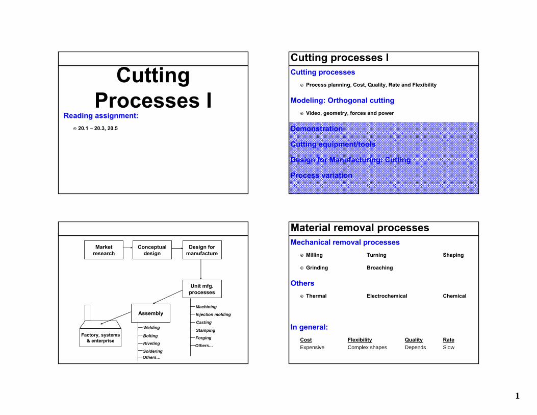
Cutting processes ICutting processes
Process planning, Cost, Quality, Rate and Flexibility
Modeling: Orthogonal cuttingVideo, geometry, forces and power
Demonstration
Cutting equipment/tools
Design for Manufacturing: Cutting
Process variation
Marketresearch
Conceptualdesign
Design formanufacture
Unit mfg.processes
Assembly
Factory, systems& enterprise
Machining
Injection molding
Casting
Stamping
ForgingBolting
Riveting
Soldering
Welding
Others…
Others…
Material removal processesMechanical removal processes
Milling Turning Shaping
Grinding Broaching
OthersThermal Electrochemical Chemical
In general:Cost Flexibility Quality RateExpensive Complex shapes Depends Slow
2
Understanding what is going onKey issues
How does cutting work?
Linking the Cost, Flexibility, Quality and Rate to process parameters
Available methods to design process parameters:Analytic Numerical Experimental
Process planning & cutting process
CuttingProcess
Settings:- Speed- Tool orientation- Feed/depth
Inputs:- Material- Energy- Others
Materials:- Tool- Coating- Lubricant
Equipment:- Tool geometry- Machine tool- Fixture
Outputs:- Parts- Chips- Energy- Others
Today Next Next2
Steps we will take to get there
Step II:Forces
Step I:Geometry &
Motion
Step III:Material &
Power
Tool and material
Specific energy
Geometry & Motion → Forces → Material & Energy/Power
Cutting, shearing, friction
Cutting, shearing, friction
Basic cutting geometries
Orthogonal (2D) Oblique (3D)
Orthogonal → Provides insight for understanding
Oblique → Complex, diminishing returns
x
y
z
x
y
z
Geometry & Motion → Forces → Material & Energy/Power
3
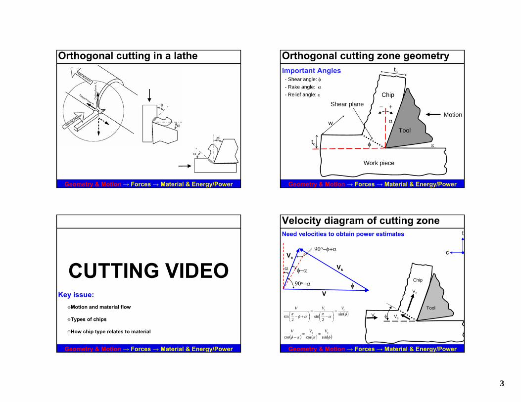
Orthogonal cutting in a lathe
Geometry & Motion → Forces → Material & Energy/Power
Orthogonal cutting zone geometryImportant Angles- Shear angle: φ- Rake angle: α- Relief angle: ε
Shear plane
tc
α
Tool
Work piece
Chip
Motion
φ
+−
to ε
w
Geometry & Motion → Forces → Material & Energy/Power
CUTTING VIDEOKey issue:
Motion and material flow
Types of chips
How chip type relates to material
Geometry & Motion → Forces → Material & Energy/Power
Velocity diagram of cutting zoneNeed velocities to obtain power estimates
c
t
Chip
φ Vs
Tool
Vc
V
Vs
V
Vc
α φ−α
90ο−α
90ο−φ+α
Geometry & Motion → Forces → Material & Energy/Power
( ) ( ) ( )φααφ sincoscoscs VVV
==−
φ
( )φαπαφπ sin2
sin2
sin
cs VVV=
⎟⎠⎞
⎜⎝⎛ −
=⎟⎠⎞
⎜⎝⎛ +−
4
Cutting ratio, rFrom mass conservation:
From velocity diagram:
Cutting ratio:
cco VwtVwt ⋅⋅⋅=⋅⋅⋅ ρρ
( )( )αφ
φ−
===cos
sinrtt
VV
c
oc
Geometry & Motion → Forces → Material & Energy/Power
tc
αTool
Work piece
Chip
φ
+−
to
w
( ) ( )φαφ sincoscVV
=−
Analysis of shear strain
What does this mean:φ ↓ = γ ↑
( ) ( )αφφγ −+=+
=∆
= tancotac
cdbcAx
Geometry & Motion → Forces → Material & Energy/Power
a
cd
bφ
φ−α
A ∆x
φ
a
db
α
90−α
Cutting forces and powerWhy do we need to know the cutting force/power?
Designing parts / machine tools (power and stiffness)
Part, machine and tool deflection
Trade offs in process planning, CFQR…
Equipment suitability
Others….
Geometry & Motion → Forces → Material & Energy/Power
Cutting forcesForces:
Thrust Ft
Cutting Fc
Friction Ff
Tool normal N
Shear Fs
Chip normal Fn
Work piece
Chip c
t
α
φ
+−
Tool
Fn
Fs
N
Ff Fc
Ft
Geometry & Motion → Forces → Material & Energy/Power
5
Merchant’s diagram: Force relationshipsShear plane forces:
Tool-chip forces:
Ft
FcFn
Fs
Ff
N
Geometry & Motion → Forces → Material & Energy/Power
α
φ
R
α
βFt
Fc
N
Ff
Fn
Fs
φ
R
R R( ) ( )φφ sincos ⋅−⋅= tcs FFF
( ) ( )φφ cossin ⋅+⋅= tcn FFF
( )βµ tan==NFf
25.0: << µTypcially
( ) ( )αα cossin ⋅+⋅= tcf FFF
( ) ( )αα sincos ⋅−⋅= tc FFN
Cutting and thrust forcesFt = Fc tan (β − α)
β < α tool is pulled into part
β > α tool is pushed away
β = α no thrust force
Use high α for thin cuts?
Geometry & Motion → Forces → Material & Energy/Power
α
R
α
βFt
Fc
N
Ff
β−α
φ and τsMagnitude of shear stress varies with angle of shear plane
φmax 35 degrees0.61 radians
Fc 225 lbfα 20 degrees
0.35 radiansβ 40 degrees
0.70 radiansto 0.015 inchesw 0.075 inchesτs 70021 psi
Shear stress along shear plane
0100002000030000400005000060000700008000090000
100000
0 15 30 45 60 75 90
φ [degrees]
τs [p
si]
Geometry & Motion → Forces → Material & Energy/Power
( ) ( )
( ) wtFF
AF
o
tc
s
ss
⋅⎥⎦⎤
⎢⎣⎡
⋅−⋅==
φ
φφτ
sin
sincos
Merchant’s relationshipMerchant’s assumption:
Shear angle adjusts to maximize τs
( ) ( )
( ) wtFF
AF
o
tc
s
ss
⋅⎥⎦⎤
⎢⎣⎡
⋅−⋅==
φ
φφτ
sin
sincos
Geometry & Motion → Forces → Material & Energy/Power
( ) ( ) ( ) ( ) ( ) ( )⎥⎦
⎤⎢⎣
⎡⋅−
⋅=⎥
⎦
⎤⎢⎣
⎡⋅⋅⋅−−
⋅= φφφφφφ
φτ 2sin2coscossin2sincos 22
c
t
o
c
c
t
o
cs
FF
wtF
FF
wtF
dd
( )( )
( )( )
( )( )αβ
αβφφ
φφ
φτ
−−
−==⎥⎦
⎤⎢⎣
⎡−→=
cossin
2sin2cos0
2sin2cos0
c
ts
FF
dd
( )αβ −= tanc
t
FF
( ) ( ) ( ) ( ) ( )αβφαβφαβφ −+==−⋅−−⋅ 2cos0sin2sincos2cos
22422 αβπφπαβφ +−=→=−+ Merchant’s relationship [radians]
6
The use of Merchant’s relationship
As rake angle ↓ or as friction angle ↑Shear angle ↓
Chip thickness ↑
Energy dissipation via shear ↑
Heat generation ↑
Temperature ↑
Geometry & Motion → Forces → Material & Energy/Power
224αβπφ +−= Merchant’s relationship [radians]
Power/energy requirementsWhat happens to energy you put in?
Shear
Friction
Others?
Tool
Work piece
Chip
Geometry & Motion → Forces → Material & Energy/Power
Specific energy (table from Kalpajkian)
3.00 – 5.20Stainless steels
2.70 – 9.30Steels
1.60 – 5.50Cast irons
1.40 – 3.30Copper alloys
0.40 – 1.10Aluminum alloys
J / mm3
Assumed for 80 % motor efficiency
Approximate Energy Requirements in Cutting Operations
conditions certainVolumeEnergy
=su
Geometry & Motion → Forces → Material & Energy/Power
Power and specific energySpecific energies to consider:
VtwVFu
o
ct ⋅⋅
⋅=
VtwVFu
o
sss ⋅⋅
⋅=
VtwVF
uo
cff ⋅⋅
⋅=
~75% ~20%
Others
~5% 100%
( ) VVu ss
s ⋅=φ
τsin
γτ ⋅= ssu
Geometry & Motion → Forces → Material & Energy/Power
Shear + Friction + Others = Total
7
Cutting Processes IIReading assignment:
20.6 – 20.8
21.1 – 21.6, 21.13
Cutting processes IICutting processes
Process planning, Cost, Quality, Rate and Flexibility
Modeling: Orthogonal CuttingVideo, geometry, forces and power
Demonstration
Equipment and tools
Design for Manufacturing
Process variation
Marketresearch
Conceptualdesign
Design formanufacture
Unit mfg.processes
Assembly
Factory, systems& enterprise
Machining
Injection molding
Casting
Stamping
ForgingBolting
Riveting
Soldering
Welding
Others…
Others…
Process planning & cutting process
CuttingProcess
Settings:- Speed- Tool orientation- Feed/depth
Inputs:- Material- Energy- Others
Materials:- Tool- Coating- Lubricant
Equipment:- Tool geometry- Machine tool- Fixture
Outputs:- Parts- Chips- Energy- Others
Last Today Next
8
Review: Cutting forcesForces:
Thrust Ft
Cutting Fc
Friction Ff
Tool normal N
Shear Fs
Chip normal Fn
Work piece
Chip c
t
α
φ
+−
Tool
Fn
Fs
N
Ff Fc
Ft
τs on shear plane if shear plane at φ
0
10000
20000
30000
40000
50000
60000
70000
80000
0 15 30 45 60 75 90
φ [degrees]
τs [p
si]
Merchant’s minimum energy assumptionAssumption: φ adjusts to value that minimizes cutting energy
If Energy need to cut is minimized, Fc is minimized for a given V
Fc is minimum when shear plane is plane of maximum shear stress
Example: Fc = minimum and τs = maximum for φ = 35o (for same α and β)
Fc dependance on of φ
0100200300400500
600700800900
1000
0 15 30 45 60 75 90φ [degrees]
F c [l
bf]
( ) VFPEt ccutcut ⋅==
∂∂
Minimize Minimized Minimized Constant
Merchant’s relationshipMerchant’s relationship:
It is an idealization, not always accurate, BUT the trend is consistent224αβπφ +−=
Chart adapted from: Metal Cutting Theory and Practice, Stephenson and Agapiou
Review: Power and specific energySpecific energies to consider:
VtwVFu
o
ct ⋅⋅
⋅=
VtwVFu
o
sss ⋅⋅
⋅=
VtwVF
uo
cff ⋅⋅
⋅=
~75% ~20%
Others
~5% 100%
( ) VVu ss
s ⋅=φ
τsin
γτ ⋅= ssu
Shear energy + Friction energy + Others = Total energy
9
Chip
α
φ
+−
Fs Ff
Fc
V
Vchip
Vs
Not deformed
PlasticallyDeformed
Caution on modeling and realityOur assumptions:
Slow, orthogonal cutting
Material properties invariant
Constant temperature
Simple sliding friction
No strain hardening
Use our analysis for:Trends & building intuition
Basis for detailed study
Chip types (source: Kalpajkian)
A) Continuous chip with narrow primary shear zoneDuctile materials @ high speed
Bad for automation (use chip breakers)
B) Secondary shear zone at chip-tool interfaceSecondary shear zone -> increased energy dissipation
A B
Source: Kalpajkian
Chip types (source: Kalpajkian)
D) Continuous chip with build up edge (BUE)High plastic working and bad for automation
E) Serrated chip:Low thermal conductivity materials
F) Discontinuous chip (good chips)Low ductility materials and/or negative rake angles
FED
Source: Kalpajkian
10
CUTTINGDEMONSTRATION
ExampleGiven:
to w ω Plathe
Find:Velocity at which lathe stalls
Cutting force
TOOL MATERIALS
AND TOOL WEAR
Cutting tool requirementsMaintain:
Hardness at operating temperature
Toughness
Low wear rate
Should be easy to repair/sharpen
Tool-part combination should be chemically inert Diamond and steel….
11
Cutting tool characteristicsWhy do we worry about tool wear?
Tool can cease to cut Dimensional accuracy
Surface finish Cutting force/power
Cost Flexibility Rate Quality
Is a function of many parametersCoolant Geometry Lubricant Process parameters
Cutting tools: Geometry
Source: Kalpajkian
Cutting tools: Geometry
Source: Kalpajkian
Tooling hardness and temperatureThings to note:
Performance ↑
Rate of change ↓
time
12
Temperature and wearDiffusion is thought to dominate crater wear
This is a function of temperature
Source: Kalpajkian Source: Kalpajkian
Tool wear up closeCrater wear affected by same parameters as flank wear
In addition:
Material affinity and temperature
Crater wearDepth of cut
Flank wear
Source: Kalpajkian
Taylor’s wear relationship (flank wear)
Relationship between tool life and cutting speedUse to set optimum cutting speed for CFRQ
Represents a given wear condition
Define wear condition for failure
Defining tool failureWear “snowballs” to set limit
Force/power increase to set limit
Surface finish becomes unacceptable
Wear land size for given process
13
Source: Kalpajkian
Taylor’s wear relationship (flank wear)
C=⋅ ntv
) fpm ( velocity cuttingv = (min) failure totimet =
C = constant & n = exponent (from experimental data)
Source: Kalpajkian
Taylor’s tool life curves (Experimental)
Coefficient n varies from:Steels Ceramics
0.1 0.7
As n ↑, wear is less sensitive to cutting speed
C=⋅ ntv
) fpm ( velocity cuttingv =
(min) failure totimet =
Preventing tool failure with coatingsTools may be coated for many reasons:
Chemically inert
Temperature resistance
Surface energy/specific energy
Low friction
Common coatingsTitanium nitride (TiN)
Cubic boron nitride (cBN)
Multi-phase coatings
Multi-phase coatingLayers ½ – 10 µm thick
CUTTING PROCESS
DFM
14
DFM for cutting: Surface roughnessSurface roughness:
Definition
Depends on :Mass removed
Size of tool
Cutter
Speed
Finish by process (source = machinery handbook)
DFM for cutting: Part geometryThin sections and tubes (vibration)
Overhanging parts
Inclined planes and drilling….
DFM for cutting: Ala featuresUse common dimensions / parts / shapes / sizes
Proper tolerance
Use common/important datums
Standard features (i.e. don’t use octagon shaped holes)
15
DFM for cutting: Ala toolingAvoid deep pockets and holes
Design should include real shape tool makesTapped holes
Pocket corners
DFM for cutting: Ala equipmentBeware of fixturing needs
Minimize number of fixture cycles
Design an interface for part-fixture
Machine and tool access to create features