Cardiac Implantable Electronic Devices and Magnetic Resonance ImagingSung Ho Hwang1, Tae Hoon Kim2, Hwan Seok Yong3, Young-Hoon Kim4
1Department of Radiology, Korea University Anam Hospital, Seoul, Korea2 Department of Radiology and Research Institute of Radiological Science, Yonsei University Health System, Seoul, Korea
3Department of Radiology, Korea University Guro Hospital, Seoul, Korea4 Division of Cardiology, Department of Internal Medicine, Korea University Anam Hospital, Seoul, Korea
Received: November 7, 2016Revised: November 30, 2016Accepted: November 30, 2016
Corresponding authorSung Ho Hwang, MD, PhDDepartment of Radiology, Korea University Anam Hospital, 73 Inchon-ro, Seongbuk-gu, Seoul 02841, KoreaTel: 82-2-920-5657Fax: 82-2-929-3796E-mail: [email protected]
Magnetic resonance imaging (MRI) is an excellent body imaging modality. One limitation of MRI is that the physical environment may be a risk for patients with implantable metallic devices. In the past, a cardiac implantable electronic device (CIED) was an absolute MRI contraindication. However, since the introduction of MRI-conditional CIED, the indication for MRI examination has progressed significantly. Cardiac magnetic resonance (CMR) examination can also be per-formed restrictively in patients with MRI-conditional CIED. With the physical MRI environment, the CIED located near the heart can impact especially a CMR examination focused on the heart. Furthermore, in basis of the physical MRI environment, CMR techniques have been de-signed for the visualization of a continuously beating heart with minimal image artifact. There-fore, physicians should be familiar with prerequisite conditions for a safe CMR, and prepare the CMR protocol to minimize CIED-related artifacts on CMR images.
Key words Heart ∙ Magnetic resonance imaging ∙ Cardiac pacemaker, artificial ∙ Cardiac resynchronization therapy devices ∙ Cardioveter-defibrillators, implantable.
INTRODUCTION
Magnetic resonance imaging (MRI) is an invaluable modality for body imaging that uses a powerful static magnetic field, rapid gradient switching, and radiofrequency (RF) pulses [1]. Cardiac magnetic resonance (CMR) examination has rapidly increased in use and application as a novel hardware, software, and process-ing technique [2]. Thus, CMR imaging has become a valuable tool for non-invasive heart disease detection and characteriza-tion [2-5]. Cardiac implantable electronic device (CIED) gener-ally refers to implanted cardiac pacing devices, such as the car-diac pacemaker (PM), implantable cardioverter defibrillator (ICD), and cardiac resynchronization therapy (CRT) [6-8]. The CIED consists of complex electronic and ferromagnetic com-ponents that can physically interact with the MRI environment [6,8]. Thus, CIED may be harmful to patients because of un-
predictable physical movement, potential for burns, or CIED malfunction during an MRI examination [6,8]. Furthermore, CIED ferromagnetic components may produce susceptibility artifacts or signal void during MRI [9,10]. Therefore, CIED has conventionally been regarded as an obstacle to both the safety and image quality of CMR examination. There is a high likeli-hood that patients with CIED will need MRI examinations over the lifetime of their CIED [11,12]. Due to recent technical developments clinical reports have indicated that MRI can be performed safely under certain specific and controlled condi-tions, even in patients with CIED [7,8]. CMR may be necessary for diagnosing underlying cardiomyopathy, evaluating arrhyth-mogenic substrates, and disease progression assessment [3,4,13]. The risk to benefit ratio may be significantly affected by the safety and image quality of CMR examination in the CIED set-ting [8,14]. Thus, when considering the clinical role of CMR in patients with CIED, knowledge of CIED and MRI physics should be obtained to ensure a safe CMR examination. This review pro-vides basic information about clinical considerations and pre-
cc This is an Open Access article distributed under the terms of the Creative Commons Attribution Non-Commercial License (http://creativecommons.org/licenses/by-nc/3.0) which permits unrestricted non-commercial use, distribution, and reproduc-tion in any medium, provided the original work is properly cited.
Sung Ho Hwang, et al CVIArequisites for CMR imaging in patients with CIED.
CIED COMPONENTS AND CLINICAL ROLES
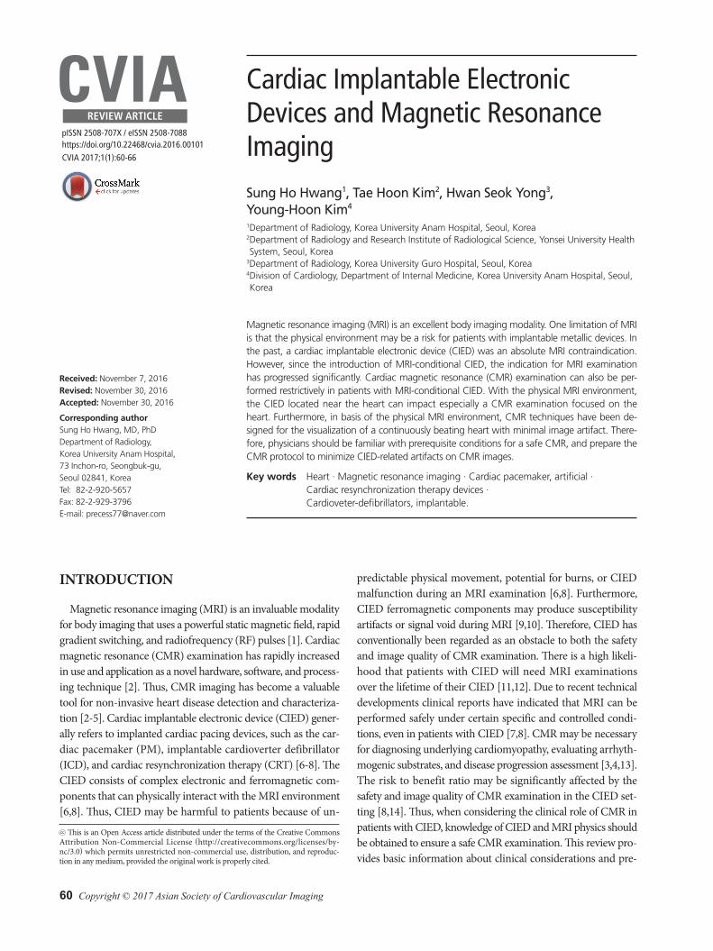
CIED main components are as follows: pulse generator, leads and electrodes (Fig. 1) [8,15]. The CIED pulse generator is pl-aced on the chest wall under the skin, and consists primarily of the battery and capacitors. The electrode is the non-insulated seg-ment of the wire used to detect cardiac arrhythmia, pacing and provide shock stimulation to the heart. CIED electrodes typically enter via the cardiac trabeculae or screw into the myocardium.
The right atrial appendage, the apex of the right ventricle, and cardiac veins along the lateral wall of the left ventricle are pre-ferred electrode implant sites. The size, component, and position of CIED may influence adverse event and image quality in CMR imaging [14,16]. Chest radiography is a useful imaging modal-ity for evaluating CIED physical characteristics [9,17]. Before a CMR scan, chest radiography can be used to predict the inter-action between CMR imaging and CIED.
CIED systems, including the cardiac PM, ICD, and CRT have been used to correct abnormal heart rhythm in cardiovascular diseases (Table 1) [6,8]. The cardiac PM is an electronic device that causes cardiac contraction during periods of bradycardia
Fig. 1. Components of cardiac pacemaker (PM) and implantable cardioverter defibrillator (ICD). (A) Frontal chest radiography shows a pulse generator (white arrow) and right heart chamber PM leads. (B) Radiography shows the PM pulse generator, including battery. (C) ICD includes the pulse generator, leads, and right ventricular shock coil that appears as a thick band (black arrow). (D) Lateral chest radiogra-phy shows a right ventricular lead (black arrow) and a right atrial lead (white arrow) of PM.
A B
C D
62 CVIA 2017;1(1):60-66
Safety and Image Quality of CMR with CIEDCVIAusing small electrical stimuli [18]. Cardiac PM has been used for the management of congestive heart failure combined with ventricular dyssynchrony. The ICD is a battery-powered device for generating a large amount of electrical energy used to defi-brillate the heart [8]. The clinical purpose of ICD is to terminate a life-threatening ventricular arrhythmia and prevent sudden ca-rdiac death [18]. The main components of an ICD are a pulse generator and leads that use a right ventricular short coil as a ring electrode. The ICD has a high-voltage coil electrode which appears as a thick band on chest radiography [15]. The CRT de-vice is a special cardiac PM that specifically aims to improve ef-fective coordination of cardiac systole [18]. The CRT also con-sists of a pulse generator and leads that enable both ventricles of the heart to be stimulated at the same time. The CRT can im-prove heart function, reducing the symptoms of heart failure by adjusting the timing of the heart’s systoles [18].
CIED safety in the MRI environment Research results have indicated that although many patients
with CIED have been reluctant to undergo MRI examinations,
hazardous or fatal outcomes have only occurred in a small num-ber of patients [7,17]. CIED-related hazards in MRI scanning generally arise from 3 risk sources: the static magnetic field, gra-dient magnetic fields, and RF pulses [19]. These risk sources may cause mechanical pull, heating, torque, vibration, and electrical stimulation. The threat of mechanical pull increases with the magnetic field strength, which is related to the amount of ferro-magnetic materials in the CIED [7]. CIEDs have been found to be safe beyond the first 6 weeks following implantation because healing around the CIED acts as adequate anchorage [7,8]. In the CIED pulse generator, a reed switch has been used to activate the CIED magnet mode [17]. When the electromagnetic effect is activated, dysfunction of the reed switch can cause abnormal voltage in a sensing amplifier, triggering a circuit that controls the magnet mode functional status which can be hazardous for patients with CIED [17,20]. The MRI pulsed gradient, in addi-tion to RF pulses, can induce electric currents in the CIED leads and electrodes. Furthermore, ICD shock delivery in the MRI en-vironment may be disabled by the external magnetic field [17,20]. The RF energy from an imaging sequence is nonionizing elec-tromagnetic radiation with a high frequency range [17,20]. Re-current RF pulses can induce strong RF energy deposition and tissue damage with particularly intense local heating [17,20]. The local thermal effect from RF pulses might eventually cause an increase in pacing threshold, capture loss, or arrhythmic at-tack [17,20].
MRI-conditional CIEDCIED manufacturers have invested in developing both CIED
hardware and software that will perform reliably during MRI scanning (Table 2). The United States Food and Drug Admin-istration (US-FDA) has established the following categories: 1) “MRI safe”, 2) “MRI-conditional”, and 3) “MRI unsafe”. MRI safe indicates an item that poses no known hazards in all MRI en-
Cardiac resynchronization therapy–biventricular pacemaker- QRS duration of >120 ms - Left ventricular ejection fraction <35%- Drug-refractory congestive heart failure
Table 2. Commercial MRI conditional cardiac implantable electronic device introduced in 2016: cardiac pacemaker, ICD, and CRT
Company Device Model Approved rangeBiotronik Pacemaker EVIA DR-T 3T
Pacemaker EVIA SR-T 3TPacemaker SAFIO S 3TPacemaker SOLIA S, T, JT 3TICD IFORIA 7 DR-T 1.5TICD IFORIA 7 VR-T 1.5T
Boston Scientific Pacemaker Accolade MRI SR 3TPacemaker Accolade MRI DR 3TPacemaker Ingevity MRI lead 3TPacemaker Fineline Lead 1.5TICD Autogen MRI SR 1.5TCRT Acuityx4 1.5T
Sung Ho Hwang, et al CVIAvironments [8,21]. MRI-conditional suggests a device that has no known hazard in a specified MRI environment, with speci-fied conditions for use [8,21]. The first MRI-conditional PM system was introduced in Europe by Biotronik (Berlin, Germa-ny) in 2010, and US-FDA approved the clinical use of Medtron-ic’s MRI-conditional PM (Minneapolis, MN, USA) in January 2011 [7]. Hardware alterations in MRI-conditional CIED in-clude minimization of ferromagnetic materials, specific filters to prevent over- and under-sensing, resonant frequency lead, and replacement of the Reed switch [17]. Although MRI examina-tion can be performed in patients with MRI-conditional cardiac PM using 1.5T and 3T MRI systems, a strong magnetic field strength (3T) can cause higher electromagnetic interference and local specific absorption rate (SAR), especially in an ICD that has a large battery-powered device. MRI-conditional CIED soft-ware also changes to prevent abnormal pacing during MRI scan-
ning [17]. In addition, MRI protocols should be provided in the device manufacturer specifications. The use of MRI-conditional CIED is a prerequisite for CMR imaging in patients with CIED. Furthermore, the approved CMR imaging protocol can be lim-ited by MRI system and CIED type parameters. If possible, most CIED manufacturers recommend a maximum static magnetic field strength of 1.5T, with a maximum specific SAR value of 2 W/kg for each sequence, and a maximum gradient slew rate of 200T/m/s [17]. Monitoring and resuscitation equipment must also be available during MRI examination [17]. Thus, patients with MRI-conditional CIED systems might undergo CMR scan-ning with minimal risks, when well-defined imaging and moni-toring protocols are established (Table 3).
Magnetic susceptibility artifact on MRIMagnetic susceptibility is the ability of a substance to become
magnetized [1,22]. Heterogeneous magnetization in the target tissue of interest results in a difference in processional frequency and phase [1,22]. This causes signal loss and dephasing at the target tissue interface. Ferromagnetic objects have a very high magnetic susceptibility and can distort images, which is more prominent in gradient echo sequences. In patients with CIED, the main cause of susceptibility artifact is the CIED ferromag-netic pulse generator within the CMR imaging volume. The fol-lowing recommendations can help minimize susceptibility ar-tifact: 1) adjust the MRI scan range to avoid the artifact, 2) use a spin echo sequence instead of gradient echo, and 3) use a short echo time (TE) with a broad bandwidth to minimize dephasing [1,16,22]. The CIED can interfere with the diagnostic value of CMR imaging because the CIED ferromagnetic components have magnetic susceptibilities that are very different from hu-man tissue.
CIED-related artifact in CMR imagingThe extent of CIED-induced artifact is mostly affected by the
CIED pulse generator, and CMR protocol [16]. The CIED lead
Table 3. MRI recommendations for patients with a CIED
Before MRI examination Identify the MRI-conditional components - MRI-conditional CIED specifications- CIED body location - CIED implant date (>6 weeks after implantation)- No broken or fracture CIED leads
Program the CIED to the appropriate MRI mode During MRI examination
Limit the static magnetic field strength to 1.5T, if possibleLimit the specific absorption rate to less than 2 W/kg of body weightLimit maximum gradient slew rate to 200T/m/s.Minimize the number and length of sequences.
After MRI examination Assess for new CIED-associated abnormalities that might have developedReprogram to the original CIED setting
MRI: magnetic resonance imaging, CIED: cardiac implantable elec-tronic device
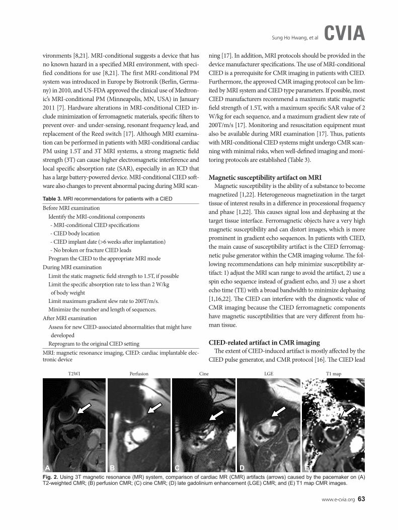
Fig. 2. Using 3T magnetic resonance (MR) system, comparison of cardiac MR (CMR) artifacts (arrows) caused by the pacemaker on (A) T2-weighted CMR; (B) perfusion CMR; (C) cine CMR; (D) late gadolinium enhancement (LGE) CMR; and (E) T1 map CMR images.
T2WI
A
Perfusion
B
Cine
C
LGE
D
T1 map
E
64 CVIA 2017;1(1):60-66
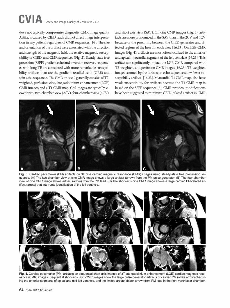
Safety and Image Quality of CMR with CIEDCVIAdoes not typically compromise diagnostic CMR image quality. Artifacts caused by CIED leads did not affect image interpreta-tion in any patient, regardless of CMR sequences [16]. The size and orientation of the artifact were associated with the direction and strength of the magnetic field, the relative magnetic suscep-tibility of CIED, and CMR sequences (Fig. 2). Steady-state free precession (SSFP) gradient echo and inversion recovery sequenc-es with long TE are associated with more remarkable suscepti-bility artifacts than are the gradient-recalled-echo (GRE) and spin echo sequences. The CMR protocol generally consists of T2- weighted, perfusion, cine, late gadolinium enhancement (LGE) CMR images, and a T1 CMR map. CM images are typically vi-ewed with: two-chamber view (2CV), four-chamber view (4CV),
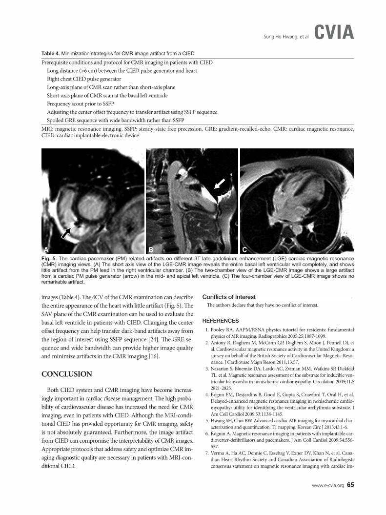
and short axis view (SAV). On cine CMR images (Fig. 3), arti-facts are more pronounced in the SAV than in the 2CV and 4CV because of the proximity between the CIED generator and af-fected regions of the heart in each view [16,23]. On LGE-CMR images (Fig. 4), artifacts are most often localized to the anterior and apical myocardial segment of the left ventricle [16,23]. This artifact can significantly impact the LGE-CMR compared with T2-weighted, and perfusion CMR images [16,23]. T2-weighted images scanned by the turbo spin echo sequence show fewer su-sceptibility artifacts [16,23]. Myocardial T1 CMR maps also have weak susceptibility for artifacts because the T1 CMR map is based on the SSFP sequence [5]. CMR protocol modifications have been suggested to minimize CEID-related artifact in CMR
Fig. 3. Cardiac pacemaker (PM) artifacts on 3T cine cardiac magnetic resonance (CMR) images using steady-state free precession se-quence. (A) The two-chamber view of cine CMR image shows a large artifact (arrow) from the PM pulse generator. (B) The four-chamber view of cine CMR image shows artifact (arrow) from the PM lead. (C) The short-axis cine CMR image shows a large cardiac PM-related ar-tifact (arrow) that interrupts identification of the left ventricle.
A B C
Fig. 4. Cardiac pacemaker (PM) artifacts on sequential short-axis images of 3T late gadolinium enhancement (LGE) cardiac magnetic reso-nance (CMR) images. Sequential short-axis LGE-CMR images show the large pulse generator artifacts of cardiac PM (white arrow) obscur-ing the anterior segments of apical and mid-left ventricle, and the limited artifact (black arrow) from PM lead in the right ventricular chamber.
www.e-cvia.org 65
Sung Ho Hwang, et al CVIA
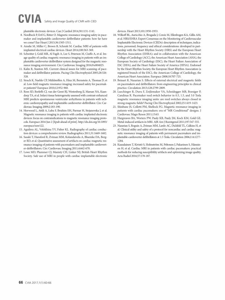
images (Table 4). The 4CV of the CMR examination can describe the entire appearance of the heart with little artifact (Fig. 5). The SAV plane of the CMR examination can be used to evaluate the basal left ventricle in patients with CIED. Changing the center offset frequency can help transfer dark-band artifacts away from the region of interest using SSFP sequence [24]. The GRE se-quence and wide bandwidth can provide higher image quality and minimize artifacts in the CMR imaging [16].
CONCLUSION
Both CIED system and CMR imaging have become increas-ingly important in cardiac disease management. The high proba-bility of cardiovascular disease has increased the need for CMR imaging, even in patients with CIED. Although the MRI-condi-tional CIED has provided opportunity for CMR imaging, safety is not absolutely guaranteed. Furthermore, the image artifact from CIED can compromise the interpretability of CMR images. Appropriate protocols that address safety and optimize CMR im-aging diagnostic quality are necessary in patients with MRI-con-ditional CIED.
Conflicts of InterestThe authors declare that they have no conflict of interest.
REFERENCES
1. Pooley RA. AAPM/RSNA physics tutorial for residents: fundamental physics of MR imaging. Radiographics 2005;25:1087-1099.
2. Antony R, Daghem M, McCann GP, Daghem S, Moon J, Pennell DJ, et al. Cardiovascular magnetic resonance activity in the United Kingdom: a survey on behalf of the British Society of Cardiovascular Magnetic Reso-nance. J Cardiovasc Magn Reson 2011;13:57.
3. Nazarian S, Bluemke DA, Lardo AC, Zviman MM, Watkins SP, Dickfeld TL, et al. Magnetic resonance assessment of the substrate for inducible ven-tricular tachycardia in nonischemic cardiomyopathy. Circulation 2005;112: 2821-2825.
4. Bogun FM, Desjardins B, Good E, Gupta S, Crawford T, Oral H, et al. Delayed-enhanced magnetic resonance imaging in nonischemic cardio-myopathy: utility for identifying the ventricular arrhythmia substrate. J Am Coll Cardiol 2009;53:1138-1145.
5. Hwang SH, Choi BW. Advanced cardiac MR imaging for myocardial char-acterization and quantification: T1 mapping. Korean Circ J 2013;43:1-6.
6. Roguin A. Magnetic resonance imaging in patients with implantable car-dioverter-defibrillators and pacemakers. J Am Coll Cardiol 2009;54:556-557.
7. Verma A, Ha AC, Dennie C, Essebag V, Exner DV, Khan N, et al. Cana-dian Heart Rhythm Society and Canadian Association of Radiologists consensus statement on magnetic resonance imaging with cardiac im-
Table 4. Minimization strategies for CMR image artifact from a CIED
Prerequisite conditions and protocol for CMR imaging in patients with CIEDLong distance (>6 cm) between the CIED pulse generator and heartRight chest CIED pulse generator Long-axis plane of CMR scan rather than short-axis plane Short-axis plane of CMR scan at the basal left ventricle Frequency scout prior to SSFPAdjusting the center offset frequency to transfer artifact using SSFP sequence Spoiled GRE sequence with wide bandwidth rather than SSFP
MRI: magnetic resonance imaging, SSFP: steady-state free precession, GRE: gradient-recalled-echo, CMR: cardiac magnetic resonance, CIED: cardiac implantable electronic device
Fig. 5. The cardiac pacemaker (PM)-related artifacts on different 3T late gadolinium enhancement (LGE) cardiac magnetic resonance (CMR) imaging views. (A) The short axis view of the LGE-CMR image reveals the entire basal left ventricular wall completely, and shows little artifact from the PM lead in the right ventricular chamber. (B) The two-chamber view of the LGE-CMR image shows a large artifact from a cardiac PM pulse generator (arrow) in the mid- and apical left ventricle. (C) The four-chamber view of LGE-CMR image shows no remarkable artifact.
A B C
66 CVIA 2017;1(1):60-66
Safety and Image Quality of CMR with CIEDCVIAplantable electronic devices. Can J Cardiol 2014;30:1131-1141.
8. Nordbeck P, Ertl G, Ritter O. Magnetic resonance imaging safety in pace-maker and implantable cardioverter defibrillator patients: how far have we come? Eur Heart J 2015;36:1505-1511.
9. Ainslie M, Miller C, Brown B, Schmitt M. Cardiac MRI of patients with implanted electrical cardiac devices. Heart 2014;100:363-369.
10. Schwitter J, Gold MR, Al Fagih A, Lee S, Peterson M, Ciuffo A, et al. Im-age quality of cardiac magnetic resonance imaging in patients with an im-plantable cardioverter defibrillator system designed for the magnetic reso-nance imaging environment. Circ Cardiovasc Imaging 2016;9:e004025.
11. Kalin R, Stanton MS. Current clinical issues for MRI scanning of pace-maker and defibrillator patients. Pacing Clin Electrophysiol 2005;28:326-328.
12. Strach K, Naehle CP, Mühlsteffen A, Hinz M, Bernstein A, Thomas D, et al. Low-field magnetic resonance imaging: increased safety for pacemak-er patients? Europace 2010;12:952-960.
13. Roes SD, Borleffs CJ, van der Geest RJ, Westenberg JJ, Marsan NA, Kaan-dorp TA, et al. Infarct tissue heterogeneity assessed with contrast-enhanced MRI predicts spontaneous ventricular arrhythmia in patients with isch-emic cardiomyopathy and implantable cardioverter-defibrillator. Circ Car-diovasc Imaging 2009;2:183-190.
14. Horwood L, Attili A, Luba F, Ibrahim EH, Parmar H, Stojanovska J, et al. Magnetic resonance imaging in patients with cardiac implanted electronic devices: focus on contraindications to magnetic resonance imaging proto-cols. Europace 2016 Jun 2 [Epub ahead of print]. http://dx.doi.org/10.1093/europace/euw122.
15. Aguilera AL, Volokhina YV, Fisher KL. Radiography of cardiac conduc-tion devices: a comprehensive review. Radiographics 2011;31:1669-1682.
16. Sasaki T, Hansford R, Zviman MM, Kolandaivelu A, Bluemke DA, Berg-er RD, et al. Quantitative assessment of artifacts on cardiac magnetic res-onance imaging of patients with pacemakers and implantable cardiovert-er-defibrillators. Circ Cardiovasc Imaging 2011;4:662-670.
17. Lowe MD, Plummer CJ, Manisty CH, Linker NJ; British Heart Rhythm Society. Safe use of MRI in people with cardiac implantable electronic
devices. Heart 2015;101:1950-1953.18. Wilkoff BL, Auricchio A, Brugada J, Cowie M, Ellenbogen KA, Gillis AM,
et al. HRS/EHRA Expert Consensus on the Monitoring of Cardiovascular Implantable Electronic Devices (CIEDs): description of techniques, indica-tions, personnel, frequency and ethical considerations: developed in part-nership with the Heart Rhythm Society (HRS) and the European Heart Rhythm Association (EHRA); and in collaboration with the American College of Cardiology (ACC), the American Heart Association (AHA), the European Society of Cardiology (ESC), the Heart Failure Association of ESC (HFA), and the Heart Failure Society of America (HFSA). Endorsed by the Heart Rhythm Society, the European Heart Rhythm Association (a registered branch of the ESC), the American College of Cardiology, the American Heart Association. Europace 2008;10:707-725.
19. Beinart R, Nazarian S. Effects of external electrical and magnetic fields on pacemakers and defibrillators: from engineering principles to clinical practice. Circulation 2013;128:2799-2809.
20. Luechinger R, Duru F, Zeijlemaker VA, Scheidegger MB, Boesiger P, Candinas R. Pacemaker reed switch behavior in 0.5, 1.5, and 3.0 Tesla magnetic resonance imaging units: are reed switches always closed in strong magnetic fields? Pacing Clin Electrophysiol 2002;25:1419-1423.
21. Shinbane JS, Colletti PM, Shellock FG. Magnetic resonance imaging in patients with cardiac pacemakers: era of “MR Conditional” designs. J Cardiovasc Magn Reson 2011;13:63.
22. Hargreaves BA, Worters PW, Pauly KB, Pauly JM, Koch KM, Gold GE. Metal-induced artifacts in MRI. AJR Am J Roentgenol 2011;197:547-555.
23. Nazarian S, Roguin A, Zviman MM, Lardo AC, Dickfeld TL, Calkins H, et al. Clinical utility and safety of a protocol for noncardiac and cardiac mag-netic resonance imaging of patients with permanent pacemakers and im-plantable-cardioverter defibrillators at 1.5 Tesla. Circulation 2006;114:1277-1284.
24. Kaasalainen T, Kivistö S, Holmström M, Peltonen J, Pakarinen S, Hännin-en H, et al. Cardiac MRI in patients with cardiac pacemakers: practical methods for reducing susceptibility artifacts and optimizing image quality. Acta Radiol 2016;57:178-187.