Scholars' Mine Scholars' Mine Masters Theses Student Theses and Dissertations Spring 2018 Cyber-physical security of an electric microgrid Cyber-physical security of an electric microgrid Prashanth Palaniswamy Follow this and additional works at: https://scholarsmine.mst.edu/masters_theses Part of the Computer Sciences Commons Department: Department: Recommended Citation Recommended Citation Palaniswamy, Prashanth, "Cyber-physical security of an electric microgrid" (2018). Masters Theses. 7776. https://scholarsmine.mst.edu/masters_theses/7776 This thesis is brought to you by Scholars' Mine, a service of the Missouri S&T Library and Learning Resources. This work is protected by U. S. Copyright Law. Unauthorized use including reproduction for redistribution requires the permission of the copyright holder. For more information, please contact [email protected].
Transcript
Scholars' Mine Scholars' Mine
Masters Theses Student Theses and Dissertations
Spring 2018
Cyber-physical security of an electric microgrid Cyber-physical security of an electric microgrid
Prashanth Palaniswamy
Follow this and additional works at: https://scholarsmine.mst.edu/masters_theses
Part of the Computer Sciences Commons
Department: Department:
Recommended Citation Recommended Citation Palaniswamy, Prashanth, "Cyber-physical security of an electric microgrid" (2018). Masters Theses. 7776. https://scholarsmine.mst.edu/masters_theses/7776
This thesis is brought to you by Scholars' Mine, a service of the Missouri S&T Library and Learning Resources. This work is protected by U. S. Copyright Law. Unauthorized use including reproduction for redistribution requires the permission of the copyright holder. For more information, please contact [email protected].
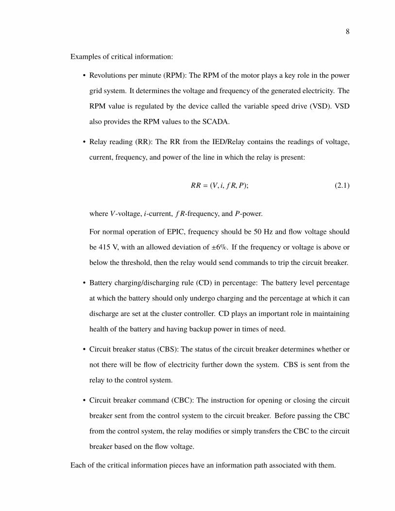
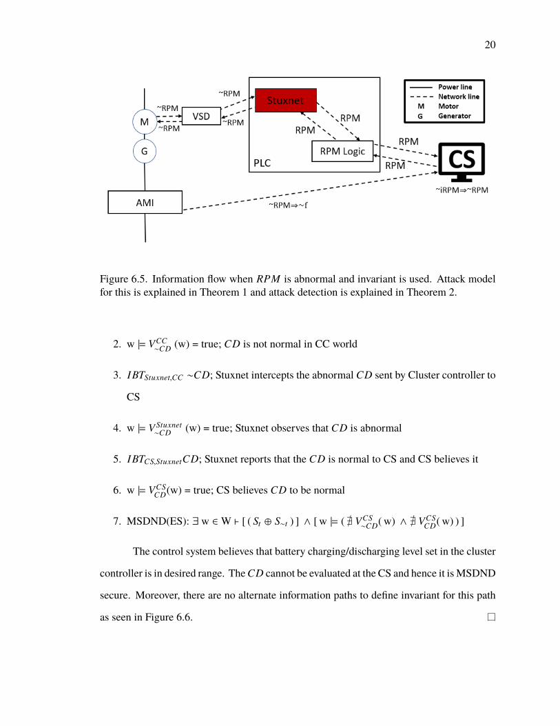
6.5. Information flow when RPM is abnormal and invariant is used. Attack modelfor this is explained in Theorem 1 and attack detection is explained in Theorem 2. 20
6.7. Information flow when RR is normal but the CB trips, and invariant is con-sidered. Attack model for this is explained in Theorem 4 and attack detectionis explained in Theorem 5.. . . . . . . . . . . . . . . . . . . . . . . . . . . . . . . . . . . . . . . . . . . . . . . . . . . . . . . . . . . 25
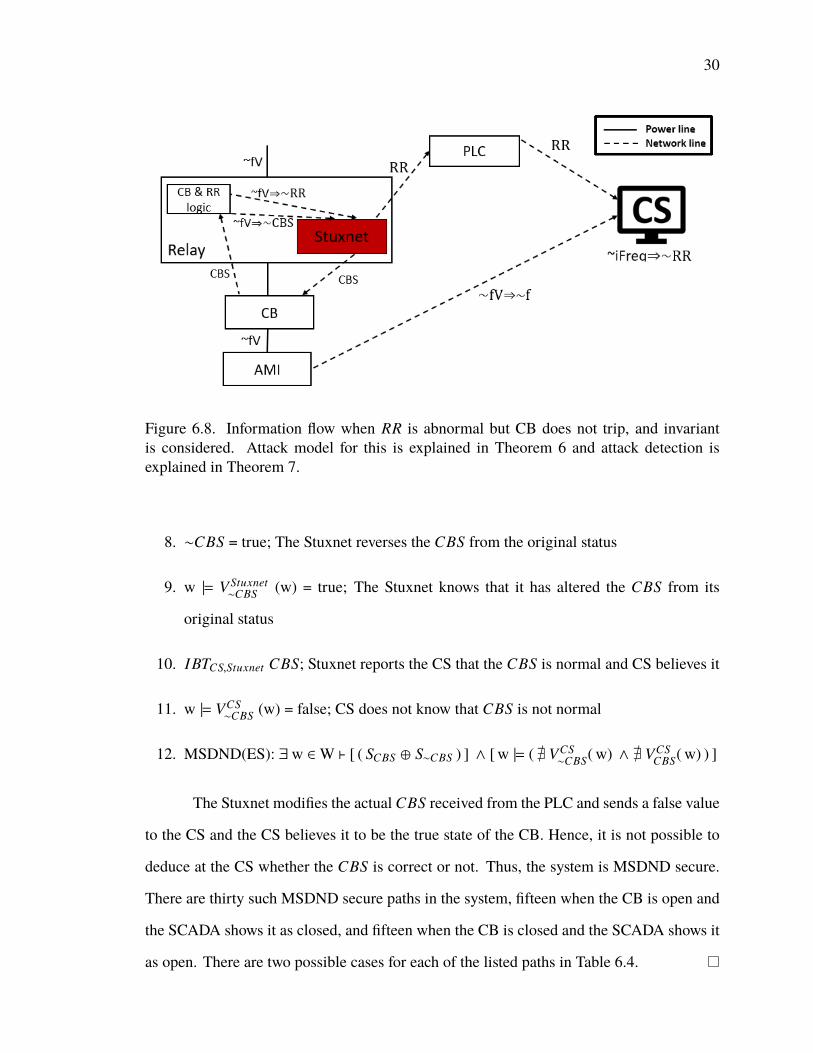
6.8. Information flow when RR is abnormal but CB does not trip, and invariantis considered. Attack model for this is explained in Theorem 6 and attackdetection is explained in Theorem 7. . . . . . . . . . . . . . . . . . . . . . . . . . . . . . . . . . . . . . . . . . . . . . . . . 30
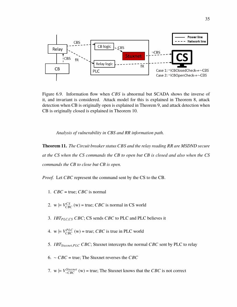
6.9. Information flow when CBS is abnormal but SCADA shows the inverse of it,and invariant is considered. Attack model for this is explained in Theorem 8,attack detection when CB is originally open is explained in Theorem 9, andattack detection when CB is originally closed is explained in Theorem 10. . . . . . . 35
6.10. Information flowwhenCBS and RR are abnormal, and invariant is considered.Attack model for this is explained in Theorem 11, attack detection when CBis originally closed is explained in Theorem 12, and attack detection when CBis originally open is explained in Theorem 13. . . . . . . . . . . . . . . . . . . . . . . . . . . . . . . . . . . . . . 42
viii
6.11. Information flow when RPM and RR are actually abnormal and invariantis considered. Attack model for this is explained in Theorem 14. Attackdetection is explained in Theorem 15. . . . . . . . . . . . . . . . . . . . . . . . . . . . . . . . . . . . . . . . . . . . . . . 47
The system is not MSDND secure as we have valuation function for normal working
of the system as shown in Figure 6.5, and fault/threat can be detected. This can be used to
break three MSDND secure paths in the system.
Analysis of vulnerability in CD information path.
Theorem 3. The battery charging/discharging percentage CD set at the cluster controller
(CC) is MSDND secure at the control system (CS)
Proof. 1. ∼CD = true; charging/discharging percentage set is not normal
20
Figure 6.5. Information flow when RPM is abnormal and invariant is used. Attack modelfor this is explained in Theorem 1 and attack detection is explained in Theorem 2.
2. w |= VCC∼CD (w) = true; CD is not normal in CC world
3. IBTStuxnet,CC ∼CD; Stuxnet intercepts the abnormal CD sent by Cluster controller to
CS
4. w |= VStuxnet∼CD (w) = true; Stuxnet observes that CD is abnormal
5. IBTCS,StuxnetCD; Stuxnet reports that the CD is normal to CS and CS believes it
6. w |= VCSCD(w) = true; CS believes CD to be normal
7. MSDND(ES): ∃ w ∈W ` [ ( St ⊕ S∼t ) ] ∧ [ w |= ( @ VCS∼CD( w) ∧ @ VCS
CD( w) ) ]
The control system believes that battery charging/discharging level set in the cluster
controller is in desired range. TheCD cannot be evaluated at the CS and hence it isMSDND
secure. Moreover, there are no alternate information paths to define invariant for this path
as seen in Figure 6.6.
21
Figure 6.6. Information flow when CD is abnormal. Attack model for this is explained inTheorem 3.
Analysis of vulnerability in RR information path.
Theorem 4. RR (within threshold or not) information is MSDND secure when the flow
voltage is normal but the circuit breaker trips
Proof. Here, the voltage that flows through the relay is within threshold but still the circuit
breaker is tripped, i.e., CBS = open.
1. f V = true; The flow voltage is within threshold
2. w |= V Relayf V (w) = true; The relay observes that the voltage is normal
3. f V =⇒ CBS; When the flow voltage is normal, the relay sends the CB the same
command that SCADA sends to CB, so here it directs CB to remain closed
4. CBS = true; CBS is normal
5. w |= V RelayCBS (w) = true; CBS is normal in relay world
6. IBTStuxnet,Relay CBS; Stuxnet intercepts the normal CBS sent by Relay to CB
7. w |= VStuxnetCBS (w) = true; Stuxnet observes that CBS is normal
22
8. IBTCB,Stuxnet ∼CBS; The Stuxnet instructs the CB to open even though the flow
voltage is normal
9. CBS=open =⇒ RR = 0; When CB is open the relay reading is zero
10. ∼RR = true; RR is now not normal
11. w |= V Relay∼RR (w) = true; Relay observes that RR is not normal
12. IBTPLC,Relay ∼RR; Relay tells PLC that RR is not normal and PLC believes it
13. w |= V PLC∼RR (w) = true; RR is not normal in PLC world
14. IBTCS,PLC ∼RR; PLC tells CS that RR is not normal and CS believes it
15. w |= VCS∼RR (w) = true; RR is abnormal in CS, CS believes it is because of abnormal
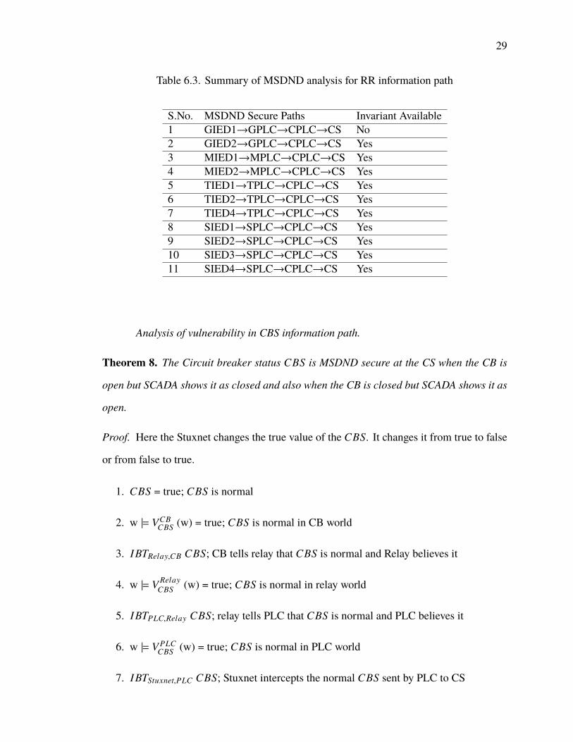
The RR reading received at the CS are all zero hence it is not possible to deduce
at the CS whether the CB trip was because of voltage beyond threshold or because of
fault/attack. Hence, the system is MSDND secure. There are eleven such MSDND secure
paths in the system as listed in the Table 6.3.
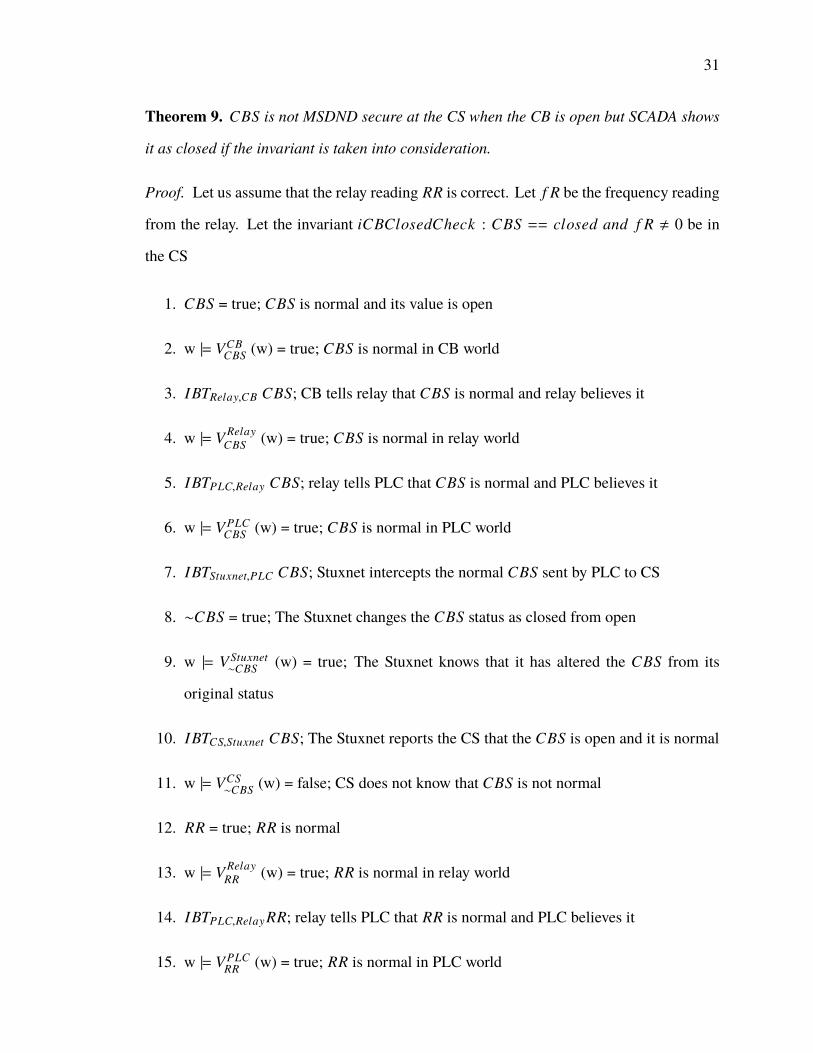
Theorem 5. RR (within threshold or not) information is not MSDND secure if the invariant
is used when the flow voltage is normal but the circuit breaker trips
Proof. Here the CBS = open and hence RR=0. To check whether the trip was because of
fault/attack we take the readings pRR from the Relays that are present immediately before
the relay that got tripped. Table 6.2 lists the relay readings that need to be used for each of
the relays that has zero reading because of tripping. If two relays are listed then any one of
them that does not have zero reading can be used. ProjpFR(pRR) = p f R. Let us assume
23
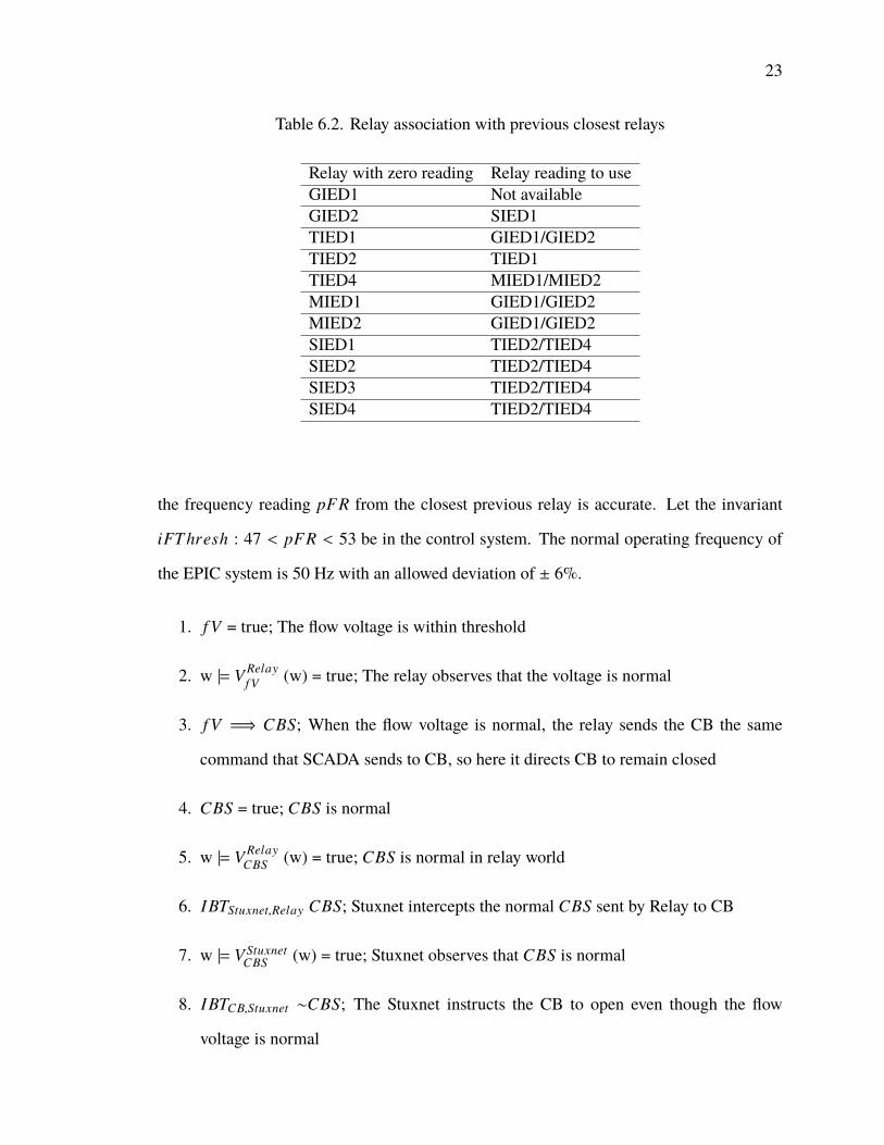
Table 6.2. Relay association with previous closest relays
Relay with zero reading Relay reading to useGIED1 Not availableGIED2 SIED1TIED1 GIED1/GIED2TIED2 TIED1TIED4 MIED1/MIED2MIED1 GIED1/GIED2MIED2 GIED1/GIED2SIED1 TIED2/TIED4SIED2 TIED2/TIED4SIED3 TIED2/TIED4SIED4 TIED2/TIED4
the frequency reading pFR from the closest previous relay is accurate. Let the invariant
iFT hresh : 47 < pFR < 53 be in the control system. The normal operating frequency of
the EPIC system is 50 Hz with an allowed deviation of ± 6%.
1. f V = true; The flow voltage is within threshold
2. w |= V Relayf V (w) = true; The relay observes that the voltage is normal
3. f V =⇒ CBS; When the flow voltage is normal, the relay sends the CB the same
command that SCADA sends to CB, so here it directs CB to remain closed
4. CBS = true; CBS is normal
5. w |= V RelayCBS (w) = true; CBS is normal in relay world
6. IBTStuxnet,Relay CBS; Stuxnet intercepts the normal CBS sent by Relay to CB
7. w |= VStuxnetCBS (w) = true; Stuxnet observes that CBS is normal
8. IBTCB,Stuxnet ∼CBS; The Stuxnet instructs the CB to open even though the flow
voltage is normal
24
9. CBS=open =⇒ RR=0; When CB is open RR is zero
10. ∼RR = true; RR is now not normal
11. w |= V Relay∼RR (w) = true; Relay observes that RR is not normal
12. IBTPLC,Relay ∼RR; Relay tells PLC that RR is not normal and PLC believes it
13. w |= V PLC∼RR (w) = true; RR is not normal in PLC world
14. IBTCS,PLC ∼RR; PLC tells CS that RR is not normal and CS believes it
15. w |= VCS∼RR (w) = true; RR is abnormal in the CS world, CS believes it is because of
abnormal flow voltage
16. IBTPLC,Relay pRR; pRR is extracted from previous closest relay to the relay in which
zero reading was shown
17. w |= V PLCpRR (w) = true; pRR is normal in PLC world
18. IBTCS,PLC pRR; PLC tells CS that pRR is normal and CS believes it
19. iFT hresh =⇒ pFR =⇒ RR (∵ProjpFR(pRR) = pFR); From our assumption that
the frequency reading pFR from the closest previous relay is accurate and the invariant
iFT hresh, the CS deduces that RR is normal
20. S” = (SiFT hresh, SRR) ; System is working normally if and if only S” is true
21. w |= VCSRR (w) = true; RR is normal in the CS world
When the RR reading received at the CS are all zero but pRR readings are all within
threshold during this period, then we can deduce that the trip in the CB was not because of
abnormal flow voltage, but because of fault/attack. Hence, the system is no longer MSDND
25
Figure 6.7. Information flow when RR is normal but the CB trips, and invariant is consid-ered. Attack model for this is explained in Theorem 4 and attack detection is explained inTheorem 5.
secure as seen in Figure 6.7. This theorem can be used to break ten MSDND secure paths
out of the eleven. The MSDND secure path when GIED1 RR shows zero can not be broken,
because there are no relays present before it. This is a design flaw in the system.
Theorem 6. RR (within threshold or not) information is MSDND secure when the flow
voltage is abnormal but the circuit breaker does not trip
Proof. Here the voltage that flows through the relay is not within threshold, but the circuit
breaker does not trip, i.e., CBS = closed. The Stuxnet changes the circuit breaker command
sent from the relay to the CB (i.e., open to closed) and masks the RR sent from the relay to
the CS.
1. ∼ f V = true; The flow voltage is not within threshold
2. w |= V Relay∼ f V (w) = true; The relay observes that the voltage is not within threshold
26
3. ∼ f V =⇒ ∼CBS; When the flow voltage is not normal, the relay ignores the SCADA
command to CB and directs it to open
4. ∼ CBS = true; CBS at relay is different from CBS at SCADA
5. w |= V Relay∼CBS (w) = true; CBS is not normal at the relay
6. IBTStuxnet,Relay ∼CBS; Stuxnet intercepts the abnormal CBS sent by relay to CB
7. w |= VStuxnet∼CBS (w) = true; Stuxnet knows that the CBS is not normal
8. IBTCB,Stuxnet CBS; Stuxnet modifies the CBS and instructs the CB that it is normal,
CB believes it
9. ∼ f V =⇒ ∼RR; The flow voltage is not normal so that reflects RR
10. ∼RR = true; RR is not normal
11. w |= V Relay∼RR (w) = true; RR is abnormal in relay world
12. IBTStuxnet,Relay ∼RR; Stuxnet intercepts the abnormal RR sent by relay to CB
13. w |= VStuxnet∼RR (w) = true; Stuxnet observes that RR is abnormal
14. IBTPLC,Stuxnet RR; Stuxnet modifies RR to make it look normal and transmits it to
PLC and PLC believes it
15. w |= V PLCRR (w) = true; RR looks normal in PLC world
16. IBTCS,PLC RR; PLC tells CS that RR is normal and CS believes it
17. w |= VCSRR (w) = true; CS believes that RR is normal and system is normally working
Analysis of vulnerability in CBS information path.
Theorem 8. The Circuit breaker status CBS is MSDND secure at the CS when the CB is
open but SCADA shows it as closed and also when the CB is closed but SCADA shows it as
open.
Proof. Here the Stuxnet changes the true value of the CBS. It changes it from true to false
or from false to true.
1. CBS = true; CBS is normal
2. w |= VCBCBS (w) = true; CBS is normal in CB world
3. IBTRelay,CB CBS; CB tells relay that CBS is normal and Relay believes it
4. w |= V RelayCBS (w) = true; CBS is normal in relay world
5. IBTPLC,Relay CBS; relay tells PLC that CBS is normal and PLC believes it
6. w |= V PLCCBS (w) = true; CBS is normal in PLC world
7. IBTStuxnet,PLC CBS; Stuxnet intercepts the normal CBS sent by PLC to CS
30
Figure 6.8. Information flow when RR is abnormal but CB does not trip, and invariantis considered. Attack model for this is explained in Theorem 6 and attack detection isexplained in Theorem 7.
8. ∼CBS = true; The Stuxnet reverses the CBS from the original status
9. w |= VStuxnet∼CBS (w) = true; The Stuxnet knows that it has altered the CBS from its
original status
10. IBTCS,Stuxnet CBS; Stuxnet reports the CS that the CBS is normal and CS believes it
11. w |= VCS∼CBS (w) = false; CS does not know that CBS is not normal
When the CB is open, the f R should be zero; if f R is not zero, then that indicates
that the CBS at the CS is not correct and it is actually closed. Hence the system is no longer
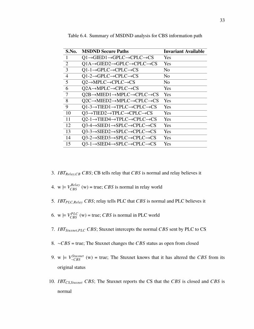
MSDND secure. This is demonstrated in Figure 6.9. This theorem can be used to break
twelve MSDND secure paths in the system out of the fifteen as shown in Table 6.4. The
three CB Q1-1, Q1-2 and Q2 does not have a relay or a smart meter next to them to validate
their state through this invariant.
Note: For the circuit breaker Q2A there are no relays next to it, wemake use of the frequency
reading from the AMI in the invariant iCBOpenCheck instead of f R.
35
Figure 6.9. Information flow when CBS is abnormal but SCADA shows the inverse ofit, and invariant is considered. Attack model for this is explained in Theorem 8, attackdetection when CB is originally open is explained in Theorem 9, and attack detection whenCB is originally closed is explained in Theorem 10.
Analysis of vulnerability in CBS and RR information path.
Theorem 11. The Circuit breaker statusCBS and the relay reading RR are MSDND secure
at the CS when the CS commands the CB to open but CB is closed and also when the CS
commands the CB to close but CB is open.
Proof. Let CBC represent the command sent by the CS to the CB.
1. CBC = true; CBC is normal
2. w |= VCSCBC (w) = true; CBC is normal in CS world
3. IBTPLC,CS CBC; CS sends CBC to PLC and PLC believes it
4. w |= V PLCCBC (w) = true; CBC is true in PLC world
5. IBTStuxnet,PLC CBC; Stuxnet intercepts the normal CBC sent by PLC to relay
6. ∼ CBC = true; The Stuxnet reverses the CBC
7. w |= VStuxnet∼CBC (w) = true; The Stuxnet knows that the CBC is not correct
36
8. IBTRelay,Stuxnet CBC; The Stuxnet reports the Relay that CBC is normal and Relay
believes it
9. w |= V Relay∼CBC (w) = false; relay does not know that CBC is abnormal
10. IBTCB,Relay CBC; relay sends CBC to CB and CB believes it to be normal
11. w |= VCB∼CBC (w) = false; CB does not know that CBC is abnormal
12. ∼CBC =⇒ ∼CBS,∼RR; When the CBC is not normal then even the CBS and RR
will not be normal
13. ∼CBS,∼RR = true; CBS and RR are not normal
14. w |= V Relay∼CBS,∼RR (w) = true; CBS and RR are not normal in relay world
15. IBTStuxnet,Relay ∼CBS,∼RR; Stuxnet intercepts the abnormal CBS and RR sent by
relay to PLC
16. w |= VStuxnet∼CBS,∼RR (w) = true; Stuxnet knows that CBS and RR are abnormal
17. IBTPLC,Stuxnet CBS, RR; The Stuxnet changes the CBS and RR values and tells the
PLC that it is normal
18. w |= V PLC∼CBS,∼RR (w) = false; CBS and RR are abnormal but in PLC world it appears
normal
19. IBTCS,PLC CBS, RR; PLC tells CS that CBS and RR are normal and CS believes that
20. w |= VCSCBS,RR (w) = true; In the CS world CBS and RR are true
21. MSDND(ES): ∃ w ∈ W ` [ ( SCBS,RR ⊕ S∼CBS,RR ) ] ∧ [ w |= ( @ VCS∼CBS,RR( w) ∧ @
VCSCBS,RR( w) ) ]
37
The Stuxnet reverses the actual CB command CBC sent from the CS and then sends
false positive RR and CBS to the CS. it is not possible to deduce at the CS whether the
CBS and RR are correct or not. Thus, the system is MSDND secure. There are thirty such
MSDND secure paths in the system, fifteen when the CS instructs open but CB is closed,
and fifteen when the CS instructs closed but CB is open. There are two possible cases for
each of the listed paths in Table 6.4.
Theorem 12. The Circuit breaker status CBS and the relay reading RR are not MSDND
secure at the CS when the CS commands the CB to open but CB is closed if the invariants
are considered.
Proof. Let us assume that the frequency reading f from the AMI is correct. Let f R be the
frequency reading in RR and let the invariant iCBRROpen : CBS == open and f == 0
and f == f R be the invariant in the CS.
1. CBC = true; CBC is normal
2. w |= VCSCBC (w) = true; CBC is normal in CS world
3. IBTPLC,CS CBC; CS sends CBC to PLC and PLC believes it
4. w |= V PLCCBC (w) = true; CBC is true in PLC world
5. IBTStuxnet,PLC CBC; Stuxnet intercepts the normal CBC sent by PLC to relay
6. ∼ CBC = true; The Stuxnet reverses the CBC
7. w |= VStuxnet∼CBC (w) = true; The Stuxnet knows that the CBC is not correct
8. IBTRelay,Stuxnet CBC; The Stuxnet reports the Relay that CBC is normal and Relay
believes it
9. w |= V Relay∼CBC (w) = false; relay does not know that CBC is abnormal
38
10. IBTCB,Relay CBC; relay sends CBC to CB and CB believes it to be normal, here
CBC=open
11. w |= VCB∼CBC (w) = false; CB does not know that CBC is abnormal
12. ∼CBC =⇒ ∼CBS,∼RR; When the CBC is not normal then even the CBS and RR
will not be normal
13. ∼CBS,∼RR = true; CBS and RR are not normal
14. w |= V Relay∼CBS,∼RR (w) = true; CBS and RR are not normal in relay world
15. IBTStuxnet,Relay ∼CBS,∼RR; Stuxnet intercepts the abnormal CBS and RR sent by
relay to PLC
16. w |= VStuxnet∼CBS,∼RR (w) = true; Stuxnet knows that CBS and RR are abnormal
17. IBTPLC,Stuxnet CBS, RR; The Stuxnet changes the CBS and RR values and tells the
PLC that it is normal
18. w |= V PLC∼CBS,∼RR (w) = false; CBS and RR are abnormal but in PLC world it appears
normal
19. IBTCS,PLC CBS, RR; PLC tells CS that CBS and RR are normal and CS believes that
20. w |= VCSCBS,RR (w) = true; In the CS world CBS and RR are true
21. ∼CBS =⇒ ∼ f ; as CBS is not normal, the AMI readings are also not normal
22. IBTCS,AMI ∼ f ; We obtain the frequency reading from the AMI at the CS
23. w |= VCS∼ f (w) = true; f is not normal in CS world
24. Proj f R(RR)= f R;
25. ∼iCBRROpen =⇒ ∼CBS,∼RR; when the invariant iCBRROpen fails, CS deduces
that CBS and RR are not normal
39
26. w |= VCS∼CBS,∼RR (w) = true; CS world now has deduced that CBS and RR are not
normal
27. S” = (SiCBRROpen, SCBS,RR) ; System is working normally if and only if S” is true
28. ∼MSDND(ES): ∃ w ∈ W ` [ ( S” ⊕ S∼CBS,RR ) ] ∧ [ w |= (∃ VCS∼CBS,RR( w) ∧ @
VCSCBS,RR( w) ) ]
If the CB is open, then f should be zero; if the RR is true, then it should match with
the corresponding AMI reading. When this is not true, we can deduce that the RR and the
CBS at the CS are incorrect as shown in Figure 6.10. This invariant can be used to break
eleven out of the fifteen MSDND secure paths. The four circuit breakers Q1-1, Q1-2, Q2
and Q2A does not have a relay next to them to validate their state through the invariant
iCBRROpen. The paths that are broken in Table 6.4 holds, but the line item 6 involving
Q2A does not have an invariant.
Theorem 13. The Circuit breaker status CBS and the relay reading RR are not MSDND
secure at the CS when the CS commands the CB to close but CB is open if the invariants
are considered.
Proof. Let us assume that the frequency reading f from the AMI is correct. Let f R be the
frequency reading in RR and let the invariant iCBRRClose : CBS == closed and f , 0
and f == f R be the invariant in the CS.
1. CBC = true; CBC is normal
2. w |= VCSCBC (w) = true; CBC is normal in CS world
3. IBTPLC,CS CBC; CS sends CBC to PLC and PLC believes it
4. w |= V PLCCBC (w) = true; CBC is true in PLC world
5. IBTStuxnet,PLC CBC; Stuxnet intercepts the normal CBC sent by PLC to relay
40
6. ∼ CBC = true; The Stuxnet reverses the CBC
7. w |= VStuxnet∼CBC (w) = true; The Stuxnet knows that the CBC is not correct
8. IBTRelay,Stuxnet CBC; The Stuxnet reports the Relay that CBC is normal and Relay
believes it
9. w |= V Relay∼CBC (w) = false; relay does not know that CBC is abnormal
10. IBTCB,Relay CBC; relay sends CBC to CB and CB believes it to be normal, here
CBC=open
11. w |= VCB∼CBC (w) = false; CB does not know that CBC is abnormal
12. ∼CBC =⇒ ∼CBS,∼RR; When the CBC is not normal then even the CBS and RR
will not be normal
13. ∼CBS,∼RR = true; CBS and RR are not normal
14. w |= V Relay∼CBS,∼RR (w) = true; CBS and RR are not normal in relay world
15. IBTStuxnet,Relay ∼CBS,∼RR; Stuxnet intercepts the abnormal CBS and RR sent by
relay to PLC
16. w |= VStuxnet∼CBS,∼RR (w) = true; Stuxnet knows that CBS and RR are abnormal
17. IBTPLC,Stuxnet CBS, RR; The Stuxnet changes the CBS and RR values and tells the
PLC that it is normal
18. w |= V PLC∼CBS,∼RR (w) = false; CBS and RR are abnormal but in PLC world it appears
normal
19. IBTCS,PLC CBS, RR; PLC tells CS that CBS and RR are normal and CS believes that
20. w |= VCSCBS,RR (w) = true; In the CS world CBS and RR are true
41
21. ∼CBS =⇒ ∼ f ; as CBS is not normal, the AMI readings are also not normal
22. IBTCS,AMI ∼ f ; We obtain the frequency reading from the AMI at the CS
23. w |= VCS∼ f (w) = true; f is not normal in CS world
24. Proj f R(RR)= f R;
25. ∼iCBRRClose =⇒ ∼CBS,∼RR; when the invariant iCBRRClose fails, CS deduces
that CBS and RR are not normal
26. w |= VCS∼CBS,RR (w) = true; CS world now has deduced that CBS and RR are abnormal
27. S” = (SiCBRRClose, SCBS,RR) ; System is working normally if and only if S” is true
28. ∼MSDND(ES): ∃ w ∈ W ` [ ( S” ⊕ S∼CBS,RR ) ] ∧ [ w |= (∃ VCS∼CBS,RR( w) ∧ @
VCSCBS,RR( w) ) ]
If the CB is closed, then f should not be zero; if the RR is true, then it should match
with the corresponding AMI reading. When this is not true, we can deduce that the RR
and the CBS at the CS are incorrect as shown in Figure 6.10. This invariant can be used to
break eleven out of the fifteen MSDND secure paths. The four circuit breakers Q1-1, Q1-2,
Q2 and Q2A does not have a relay next to them to validate their state through the invariant
iCBRRClose. The paths that are broken in Table 6.4 holds, but the line item 6 involving
Q2A does not have an invariant.
• Multi-point attacks
Analysis of vulnerability in RPM and RR information path.
Theorem 14. The RPM reading RPM from VSD and the relay readings RR from the relay
are MSDND secure at the Control System (CS) when RPM and RR are not normal but the
readings are normal.
42
Figure 6.10. Information flowwhenCBS and RR are abnormal, and invariant is considered.Attack model for this is explained in Theorem 11, attack detection when CB is originallyclosed is explained in Theorem 12, and attack detection when CB is originally open isexplained in Theorem 13.
Proof. Here the RPM reading fromVSDand the relay readings (current, voltage, frequency)
RR from the relay are incorrect at the CS. This is a multi-point attack and there are two
Stuxnets involved. One executes at the MPLC and corrupts the RR sent to the CS, the other
executes at the SPLC and corrupts the RPM reading sent to the CS.
1. ∼RPM = true; The RPM is not normal
2. w |= VVSD∼RPM (w) = true; RPM is not normal in VSD world
3. IBTStuxnet,VSD ∼RPM; Stuxnet intercepts the abnormal RPM sent by VSD to SPLC
4. w |= VStuxnet∼RPM (w) = true; Stuxnet observes that RPM is abnormal
5. IBTSPLC,Stuxnet RPM; Stuxnet modifies RPM to make it look normal and transmits
it to SPLC and SPLC believes it
6. w |= VSPLCRPM (w) = true; RPM looks normal in SPLC world
7. IBTCPLC,SPLC RPM; SPLC tells CPLC that RPM is normal and CPLC believes it
43
8. w |= VCPLCRPM (w) = true; RPM looks normal in CPLC world
9. IBTCS,CPLC RPM; CPLC tells CS that RPM is normal and CS believes it
10. w |= VCSRPM (w) = true; CS believes that RPM is normal
11. ∼RR = true; RPM is not normal so the RR is also not normal
12. w |= V Relay∼RR (w) = true; RR is not normal in relay world
13. IBTStuxnet,Relay ∼RR; Stuxnet intercepts the abnormal RR sent by relay to MPLC
14. w |= VStuxnet∼RR (w) = true; Stuxnet observes that RR is abnormal
15. IBTMPLC,Stuxnet RR; Stuxnet modifies RR to make it look normal and transmits it to
MPLC and MPLC believes it
16. w |= V MPLCRR (w) = true; RR appears normal in MPLC world
17. IBTCPLC,MPLC RR; MPLC tells CPLC that RR is normal and CPLC believes it
18. w |= VCPLCRR (w) = true; RR is normal in CPLC world
19. IBTCS,CPLC RR; CPLC tells CS that RR is normal and CS believes it
20. w |= VCSRR (w) = true; CS observes RR to be normal
21. S = (SRPM , SRR); S is a world where RR and RPM are normal
22. S” = (S∼RPM , S∼RR); S” is a world where RR and RPM are abnormal
23. MSDND(ES): ∃ w ∈ W ` [ ( S ⊕ S” ) ] ∧ [ w |= ( @ VCS∼RPM( w) ∧ @ VCS
RPM( w)∧ @
VCS∼RR( w)∧ @ VCS
RR ( w) ) ]
The CS believes the false RPM reading reported by the Stuxnet and the false
positive RR reading reported by the other Stuxnet. Therefore, RPM information and RR
are MSDND secure at the CS. There are three such MSDND secure paths in the system as
shown in Table 6.5.
44
Table 6.5. Summary of MSDND analysis for RPM and RR information path
S.No. MSDND Secure Paths InvariantAvailable
1 VSD1→SPLC→CPLC→CS andMIED2→MPLC→CPLC→CS
Yes
2 VSD2→SPLC→CPLC→CS andMIED1→MPLC→CPLC→CS
Yes
3 VSD3→SPLC→CPLC→CS andGIED2→GPLC→CPLC→CS
Yes
Theorem 15. The RPM reading RPM from VSD and the Relay Reading RR from the relay
are not MSDND secure at the Control System (CS) when RPM and RR are not normal but
the readings at CS are normal when the invariants are considered.
Proof. Let us assume the frequency reading f from the AMI is correct. Let f R be the
frequency reading from the relay. Let the invariant iRPM: RPM = 30 f and iF: f == f R
be in the control system.
1. ∼RPM = true; The RPM is not normal
2. w |= VVSD∼RPM (w) = true; RPM is not normal in VSD world
3. IBTStuxnet,VSD ∼RPM; Stuxnet intercepts the abnormal RPM sent by VSD to SPLC
4. w |= VStuxnet∼RPM (w) = true; Stuxnet observes that RPM is abnormal
5. IBTSPLC,Stuxnet RPM; Stuxnet modifies RPM to make it look normal and transmits
it to SPLC and SPLC believes it
6. w |= VSPLCRPM (w) = true; RPM looks normal in SPLC world
7. IBTCPLC,SPLC RPM; SPLC tells CPLC that RPM is normal and CPLC believes it
8. w |= VCPLCRPM (w) = true; RPM looks normal in CPLC world
45
9. IBTCS,CPLC RPM; CPLC tells CS that RPM is normal and CS believes it
10. w |= VCSRPM (w) = true; CS believes that RPM is normal
11. ∼RR = true; As RPM is not normal in the VSD world, it affects the RR in the link
below it and hence RR is not normal
12. w |= V Relay∼RR (w) = true; RR is not normal in relay world
13. IBTStuxnet,Relay ∼RR; Stuxnet intercepts the abnormal RR sent by relay to MPLC
14. w |= VStuxnet∼RR (w) = true; Stuxnet observes that RR is abnormal
15. IBTMPLC,Stuxnet RR; Stuxnet modifies RR to make it look normal and transmits it to
MPLC and MPLC believes it
16. w |= V MPLCRR (w) = true; RR appears normal in MPLC world
17. IBTCPLC,MPLC RR; MPLC tells CPLC that RR is normal and CPLC believes it
18. w |= VCPLCRR (w) = true; RR is normal in CPLC world
19. IBTCS,CPLC RR; CPLC tells CS that RR is normal and CS believes it
20. w |= VCSRR (w) = true; CS observes RR to be normal
21. S = (SRPM , SRR); S is a world where RR and RPM are normal
22. S” = (S∼RPM , S∼RR); S” is a world where RR and RPM are abnormal
23. ∼RPM =⇒ ∼ f ; as RPM is not normal, the AMI readings are also not normal
24. IBTCS,AMI ∼ f ; CS obtains the f reading from smart meter and believes it
25. ∼iRPM =⇒ ∼RPM; from the assumption that the frequency reading f from the
AMI is correct and the invariant iRPM , the CS deduces that RPM is not normal
46
26. w |= VCS∼RPM (w) = true; CS now has deduced that RPM is abnormal
27. From (2.1), Proj f R(RR)= f R,∼iF =⇒ ∼RR; from the assumption that the frequency
reading f from the AMI is correct and the invariant iF, the CS finds that RR is
abnormal
28. w |= VCS∼RR (w) = true; CS now has valuation function to know that RR is not normal
29. Sinvariant = (SiRPM , SiF); Defining a world with invariants
30. S1 = (Sinvariant , S) ; System is working normally if and if only S1 is true
31. ∼MSDND(ES): ∃ w ∈ W ` [ ( S1 ⊕ S” ) ] ∧ [ w |= (∃ VCS∼RPM( w) ∧ @ VCS
RPM( w)∧ ∃VCS∼RR( w)∧ @ VCS
RR ( w) ) ]
The system is not MSDND secure as we have a valuation function for abnormal
working of the system and hence fault/threat can be detected as shown in Figure 6.11. This
proof can be applied to break all the three MSDND secure paths listed in Table 6.5.
6.2. DATA-CENTRIC APPROACH
6.2.1. Data. The data collected from the EPIC testbed over a period of two weeks is
used to carry out the analyses. Data is extracted from a SCADA system using the Historian.
The SCADA system contains the readings from eleven relays that have voltage, current,
frequency and power readings as shown in Figure 6.12. Other readings, for example, the
circuit breaker statuses and status about the three motors like the flags set, rotation per
minute, and statuses, are also included in the SCADA system. In total, there are around two
hundred and ninety different variables from the SCADA system, and the sampling rate for
collecting the data is ten seconds.
There are two different types of data in the EPIC dataset:
Figure 6.11. Information flow when RPM and RR are actually abnormal and invariant isconsidered. Attack model for this is explained in Theorem 14. Attack detection is explainedin Theorem 15.
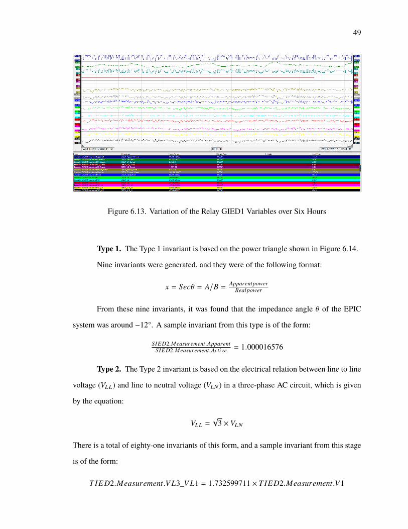
6.2.2. Invariant Generation using Linear Regression. Figure 6.13 shows the
variation of the fourteen variables of the relay GIED1 over a six-hour period. From this
figure, it is understood that certain variables vary relative to one and another and there
exists a strong linear relationship between certain variables. Throughout a power grid,
several variables are linearly related to each other, which is why linear regression would be
a suitable approach for generating invariants.
The binary data and the smart meter readings from the AMI were removed from
the processed dataset, because binary data like the breaker status would not make a valid
field for the linear regression algorithm. Linear regression was applied to the remaining
one hundred and fifty-two numeric data values of EPIC to derive mathematical relations
between them. The very high coefficient of determination (R2) of the prediction was set for
deriving invariants using linear regression for a higher accuracy. An R2 score of .99 out of
48
Figure 6.12. Reading from the Relay GIED1
1 was set for deriving invariants. The algorithm would then run through each column and
determine the mathematical relation of the form A = x × B, where A and B are column
names and x is a constant.
Care was taken to avoid duplicate invariants by considering only the upper triangular
matrix of the data frame while generating invariants. The fields A and B were rearranged
in such a way while generating invariants that x was greater than 1. This was done to avoid
generating the invariant A1B1 = 2 and B1
A1 = 0.5 differently, which would make the grouping
of invariants tedious. Filtering was done to remove the invariant relation between different
devices like frequency of relay1 with voltage of relay2 because one of them can be closed
and the other can be in open state and that time the relation might still hold just because
one of them is zero, which would not actually make sense. For an R2 score of .99, a total of
215 invariants were generated and 199 of them were categorized into nine types based on
electrical equations that obey the law of physics. The nine types of invariants are as follows:
49
Figure 6.13. Variation of the Relay GIED1 Variables over Six Hours
Type 1. The Type 1 invariant is based on the power triangle shown in Figure 6.14.
Nine invariants were generated, and they were of the following format:
x = Secθ = A/B = ApparentpowerRealpower
From these nine invariants, it was found that the impedance angle θ of the EPIC
system was around −12°. A sample invariant from this type is of the form:
‘Cyber-physical systems public working group,’ 2017, [Online], Available: https://pages.nist.gov/cpspwg/, [Accessed: 31 Oct, 2017].
Adepu, S. andMathur, A., ‘Using process invariants to detect cyber attacks on a water treat-ment system,’ in ‘IFIP International Information Security and Privacy Conference,’Springer, 2016 pp. 91–104.
Bishop, M., Computer security: art and science, Addison-Wesley Professional, 2003.
Dunaka, P. R. and McMillin, B., ‘Cyber-physical security of a chemical plant,’ in ‘HighAssurance Systems Engineering (HASE), 2017 IEEE 18th International Symposiumon,’ IEEE, 2017 pp. 33–40.
Falliere, N., Murchu, L. O., and Chien, E., ‘W32. stuxnet dossier,’ White paper, SymantecCorp., Security Response, 2011, 5(6), p. 29.
FitzPatrick, G. J. and Wollman, D. A., ‘Nist interoperability framework and action plans,’in ‘Power and Energy Society General Meeting, 2010 IEEE,’ IEEE, 2010 pp. 1–4.
Gamage, T. T., Liu, Y., Nguyen, T. A., Qiu, X., McMillin, B. M., and Crow, M. L., ‘A novelflow invariants-based approach to microgrid management,’ IEEE Transactions onSmart Grid, 2015, 6(2), pp. 516–525.
Howser, G. andMcMillin, B., ‘Amultiple security domainmodel of a drive-by-wire system,’in ‘Computer Software and Applications Conference (COMPSAC), 2013 IEEE 37thAnnual,’ IEEE, 2013 pp. 369–374.
Howser, G. andMcMillin, B., ‘A modal model of stuxnet attacks on cyber-physical systems:A matter of trust,’ in ‘Software Security and Reliability (SERE), 2014 EighthInternational Conference on,’ IEEE, 2014 pp. 225–234.
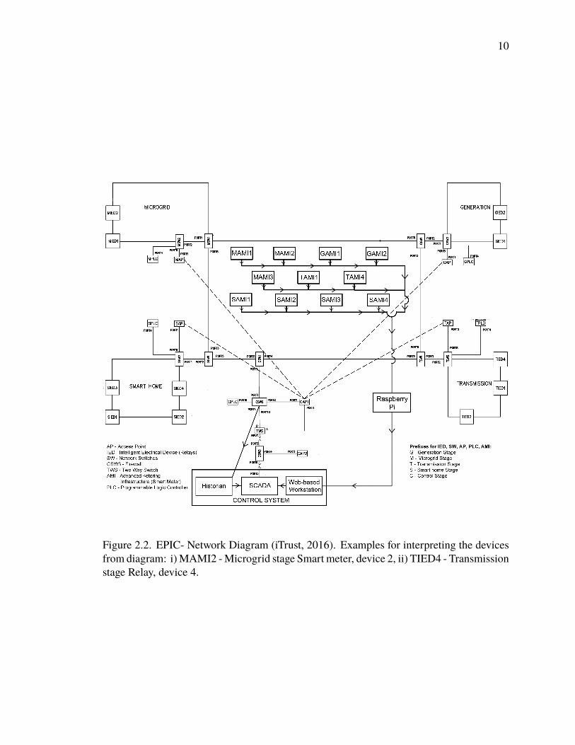
iTrust, ‘Electric power and intelligent control,’ 2016, [Online], Available: https://itrust.sutd.edu.sg/research/testbeds/electric-power-intelligent-control-epic/, [Ac-cessed: 17 Sep, 2017].
Kanteti, U. G.,Multiple security domain model of a vehicle in an automated vehicle system,Ph.D. thesis, Missouri University of Science and Technology, 2017.
61
Liau, C.-J., ‘Belief, information acquisition, and trust in multi-agent systemsâĂŤa modallogic formulation,’ Artificial Intelligence, 2003, 149(1), pp. 31–60.
Liau, C.-J., ‘A modal logic framework for multi-agent belief fusion,’ ACM Transactions onComputational Logic (TOCL), 2005, 6(1), pp. 124–174.
McMillin, B. and Roth, T., ‘Cyber-physical security and privacy in the electric smart grid,’Synthesis Lectures on Information Security, Privacy & Trust, 2017, 9(2), pp. 1–64.
Mueller, P. and Yadegari, B., ‘The stuxnet worm,’ 2012, [Online], Avail-able: https://www2.cs.arizona.edu/~collberg/Teaching/466-566/2012/Resources/presentations/2012/topic9-final/report.pdf, [Accessed: 18 Nov, 2017].
Owicki, S. and Gries, D., ‘An axiomatic proof technique for parallel programs i,’ Actainformatica, 1976, 6(4), pp. 319–340.
Paul, T., Kimball, J. W., Zawodniok, M., Roth, T. P., McMillin, B., and Chellappan, S.,‘Unified invariants for cyber-physical switched system stability,’ IEEE Transactionson Smart Grid, 2014, 5(1), pp. 112–120.
Roth, T. and McMillin, B., ‘Physical attestation in the smart grid for distributed stateverification,’ IEEE Transactions on Dependable and Secure Computing, 2016.
Sutherland, D., ‘A model of information,’ in ‘Proceedings of the 9th national computersecurity conference,’ volume 247, Washington, DC, 1986 pp. 175–183.
Thudimilla, A. and McMillin, B., ‘Multiple security domain nondeducibility air trafficsurveillance systems,’ in ‘High Assurance Systems Engineering (HASE), 2017IEEE 18th International Symposium on,’ IEEE, 2017 pp. 136–139.
Umer, M. A., Mathur, A., Junejo, K. N., and Adepu, S., ‘Integrating design and data centricapproaches to generate invariants for distributed attack detection,’ in ‘Proceedingsof the 2017 Workshop on Cyber-Physical Systems Security and PrivaCy,’ ACM,2017 pp. 131–136.
62
VITA
Prashanth Palaniswamy was born in Coimbatore, India. He received his Bachelor’s
degree in Computer Science and Engineering from Sri Ramakrishna Engineering College,
Coimbatore in May 2013. He then worked at Infosys Technologies, Mysore as a Senior
SystemsEngineer in the fields of software development and cloud computing. Afterworking
for three years he joined Missouri University of Science and Technology, USA in Aug 2016
to pursue Master’s degree in computer science. He joined Dr. Bruce McMillin’s research
group in Jan 2017 as a graduate research assistant in the field of cyber physical security
and enjoyed doing research under his guidance. He did Summer research internship at
the Singapore University of Technology and Design, Singapore under the guidance of Dr.
Aditya Mathur. In May 2018, he received his Master’s degree in Computer Science from