Cyclic Beam Bending Test for Assessment of Bond-Slip Behavior M. Soleymani Ashtiani, R. P. Dhakal, A. N. Scott & D. K. Bull Department of Civil and Natural Resources Engineering, University of Canterbury, Christchurch, New Zealand SUMMARY: Bond between reinforcement and concrete is one of the most important aspects in structural response of reinforced concrete (RC) members. Basic RC theories assume compatibility of strains between concrete and steel which is valid only if a perfect bond exists between the two materials. Therefore investigating bond properties under different loading conditions and considering various variables is of great importance. Although researchers have extensively explored bond-slip relationships for different concrete and steel types under monotonic loading using different test setups, less is reported on bond properties under reversed cyclic loading. Modified pullout tests have previously been used to investigate cyclic bond-slip relationships; nevertheless these tests do not represent the actual bond behaviour inside RC members subjected to flexural actions. This study focuses on developing a specific test setup and designing a beam specimen for cyclic bond test following RILEM recommendations for monotonic assessment of bond properties, which require a two-point loading (four-point bending) setup. The main challenge was to design a stable cyclic test setup in order to ensure no additional forces generated in the system during the test. High strength self-compacting concrete (HSSCC) beam specimens were chosen for the test; the beam specimens were designed in such a way that they could withstand load reversals. Keywords: Cyclic, Beam, Bond-Slip, High-Strength Self-Compacting Concrete 1. INTRODUCTION Bond between reinforcing bars and concrete has been the focus of many investigations in the past. Several researchers have explored bond between steel and concrete using different test setups and specimens such as direct pull-out, beam anchorage and beam-column joint tests (Popov, 1984, Alavi- Fard et al., 2002, El-Hacha et al., 2006, Desnerck et al., 2010). Nevertheless, direct pull-out test with different arrangements appears to be the most commonly preferred approach for investigating bond properties of reinforcement and concrete under both monotonic and cyclic loadings (Alavi-Fard et al., 2002, Chan et al., 2003, Campione et al., 2005, Fang, 2006, Fang et al., 2006, Cattaneo et al., 2009). Main reasons of choosing pull-out tests over the other methods were the simplicity in producing specimens and the ability of isolating the effects of different parameters on the overall bond performance. However, in most of the available pull-out test setups, concrete and steel work under different stress states; i.e. at the same time when the latter experiences tension, the former is in compression. This is not a real condition in structural members where either both concrete and steel are in tension or in compression. Especially, in the case of high strength concrete, direct pull-out tests may not necessarily represent the actual behaviour (De Almeida Filho et al., 2008). Other test setups and specimens have also been developed to replicate, more realistically, the actual stress state in real structures. In addition to the common pull-out test, RILEM (RILEM-FIP-CEB, 1973) provides a test setup and specimen specifications for a beam bending test to investigate bond between reinforcing bar and concrete under monotonic two-point flexural loading. Fig. 1.1 shows details of the beam bending test recommended by RILEM. The beam specimen comprises of two half-
Transcript
Cyclic Beam Bending Test for Assessment of
Bond-Slip Behavior M. Soleymani Ashtiani, R. P. Dhakal, A. N. Scott & D. K. Bull Department of Civil and Natural Resources Engineering, University of Canterbury, Christchurch, New Zealand
SUMMARY: Bond between reinforcement and concrete is one of the most important aspects in structural response of reinforced concrete (RC) members. Basic RC theories assume compatibility of strains between concrete and steel which is valid only if a perfect bond exists between the two materials. Therefore investigating bond properties under different loading conditions and considering various variables is of great importance. Although researchers have extensively explored bond-slip relationships for different concrete and steel types under monotonic loading using different test setups, less is reported on bond properties under reversed cyclic loading. Modified pullout tests have previously been used to investigate cyclic bond-slip relationships; nevertheless these tests do not represent the actual bond behaviour inside RC members subjected to flexural actions. This study focuses on developing a specific test setup and designing a beam specimen for cyclic bond test following RILEM recommendations for monotonic assessment of bond properties, which require a two-point loading (four-point bending) setup. The main challenge was to design a stable cyclic test setup in order to ensure no additional forces generated in the system during the test. High strength self-compacting concrete (HSSCC) beam specimens were chosen for the test; the beam specimens were designed in such a way that they could withstand load reversals. Keywords: Cyclic, Beam, Bond-Slip, High-Strength Self-Compacting Concrete 1. INTRODUCTION Bond between reinforcing bars and concrete has been the focus of many investigations in the past. Several researchers have explored bond between steel and concrete using different test setups and specimens such as direct pull-out, beam anchorage and beam-column joint tests (Popov, 1984, Alavi-Fard et al., 2002, El-Hacha et al., 2006, Desnerck et al., 2010). Nevertheless, direct pull-out test with different arrangements appears to be the most commonly preferred approach for investigating bond properties of reinforcement and concrete under both monotonic and cyclic loadings (Alavi-Fard et al., 2002, Chan et al., 2003, Campione et al., 2005, Fang, 2006, Fang et al., 2006, Cattaneo et al., 2009). Main reasons of choosing pull-out tests over the other methods were the simplicity in producing specimens and the ability of isolating the effects of different parameters on the overall bond performance. However, in most of the available pull-out test setups, concrete and steel work under different stress states; i.e. at the same time when the latter experiences tension, the former is in compression. This is not a real condition in structural members where either both concrete and steel are in tension or in compression. Especially, in the case of high strength concrete, direct pull-out tests may not necessarily represent the actual behaviour (De Almeida Filho et al., 2008). Other test setups and specimens have also been developed to replicate, more realistically, the actual stress state in real structures. In addition to the common pull-out test, RILEM (RILEM-FIP-CEB, 1973) provides a test setup and specimen specifications for a beam bending test to investigate bond between reinforcing bar and concrete under monotonic two-point flexural loading. Fig. 1.1 shows details of the beam bending test recommended by RILEM. The beam specimen comprises of two half-
beams connected to each other at the center with a steel hinge (on the top) and a deformed bar (at the bottom). This way when the specimen is loaded, the bending moment at the center of the beam is taken care of by the steel hinge (in compression) and the deformed bar (in tension) only. Therefore in the section analysis, the effect of concrete is eliminated which in turn reduces the complexity of dealing with concrete compression block. In addition to the main reinforcing steel in which the bond is assessed, there exists other reinforcement (auxiliary steel) in each half of the beam as shown in Fig. 1.1. This extra reinforcement is required to take care of the shear and bending forces as well as to represent the effect of confinement provided by transverse reinforcement (which does exist in real structural members) on the bond performance.
Figure 1.1. Details of the RILEM beam specimen for two-point monotonic loading (all dimensions are in “mm”) It should be noted that, although this test has some advantages over the direct pull-out test, due to the complexities involved in both test setup and specimen fabrication fewer studies have been performed using the RILEM beam test (El-Hacha et al., 2006, De Almeida Filho et al., 2008, Dancygier et al., 2010, Desnerck et al., 2010). RILEM pull-out and beam bending test setups and specimens were originally designed for assessing bond under monotonic loading. The direct pull-out test has already been modified by other researchers in order to allow for the cyclic loading (Alavi-Fard et al., 2002, Campione et al., 2005). However, while some modifications have been suggested for the RILEM beam test setup and specimen, all of the reported studies were performed using monotonic loading. As real structures are subjected to load reversals (earthquake, wind and live load) during their life-span, it is important to investigate their behaviour under cyclic loads. Being one of the critical characteristics of reinforced concrete (RC) structures, bond properties of steel bars and concrete need to be evaluated under cyclic loads as well. For this purpose, in this study an attempt has been made to modify the RILEM beam specimen and develop a suitable test setup capable of applying load reversals to the modified specimen. Although the alteration of the RILEM monotonic test setup and specimen brought more intricacy to the system, special attention was paid to keep the details as simplified, repeatable and applicable as possible to accommodate for practical issues.
2. EXPERIMENTAL INVESTIGATIONS 2.1. Material properties and mix design details In the present investigation, locally available materials in Christchurch, New Zealand were used in order to design a high-strength self-compacting concrete (HSSCC) mix. General Purpose Cement (GPC), fly ash (Class C), and a third generation polycarboxylic ether polymer based superplasticizer (SP) were used. Locally available coarse aggregate (semi-crushed of maximum size 13mm), fine aggregate (natural river sand), and potable water were used in both concrete mixes. Details of physical properties of the cement, fly ash, and aggregates used in the mix are described in a previous study by the authors (Soleymani Ashtiani et al., 2010). The mix design method proposed by Su et al (Su et al., 2001) and guidelines provided by EFNARC (EFNARC, 2002, EFNARC, 2005) were used in order to reach an initial mix proportioning for HSSCC and a finalized mix was obtained through a series of laboratory trials. Table 2.1.1 shows the finalized mix design for HSSCC. Table 2.1.1. Mix proportions of HSSCC Material HSSCC (kg/m3) Coarse aggregate 880 Fine aggregate 870 Cement 385 Fly ash 165 Water 165 Super-plasticizer 3.575 (0.65%) Compressive and splitting tensile strengths of the HSSCC were measured (using standard cylinders) to be 97.5 MPa and 7.7 MPa respectively at the day of test. Deformed 16 mm diameter steel reinforcement of grade 500 having yield and ultimate strengths of 560 MPa and 670 MPa respectively was used as the main deformed bar. Round 10 and 12 mm mild-steel bars of grade 300 were used as auxiliary reinforcement to replicate the confinement effects and take care of the shear and bending forces in each half of the beam specimen as explained before. 2.2. Details of the modified RILEM beam specimen Most details of the main and auxiliary reinforcement in the modified specimen were unchanged from the original RILEM (RILEM-FIP-CEB, 1973) specifications. However, some modifications were required in order to test the beams under cyclic loading. First, because high-strength concrete with higher splitting tensile strength (thus higher bond stress) was used, the bond-length between concrete and steel was reduced from 10 to 5 times bar diameter (80 mm in this case). The decision on appropriate bond-length was made based on the outcome of previous experimental studies on bond performance of HSSCC (Soleymani Ashtiani et al., 2011). Second, the position of bond-length was relocated from the center of each half-beam towards the center of the beam specimen. This alteration was adopted in order to reduce the unbonded length of the bar between the two bonded regions. This effectively reduces the potential buckling length, which in turn delays the bar buckling during the course of the test (Dhakal et al., 2002). It should be noted that in the present study, only the specimen type B, the larger specimen as stated in RILEM (RILEM-FIP-CEB, 1973), was used (Fig. 2.2.1).
Figure 2.2.1. Details of the modified RILEM beam specimen for cyclic loading (all dimensions are in “mm”) Being designed for a monotonic test, the RILEM original beam was unable to take cyclic load; because, the steel hinge at the top could only take compressive forces. Should any load reversals happen, the steel hinge starts tearing apart as soon as the compressive force reaches zero and tensile force tends to develop at the top of the beam. Therefore, a replacement for the original steel hinge recommended by RILEM was required to suit the cyclic nature of the test. For this purpose a modified steel hinge was designed and fabricated with a high-tensile pin (1100 MPa) and bearing mechanism which made it capable of taking both compression and tension with little friction involved. Fig. 2.2.1 shows the modified steel hinge both in detail, and as installed on the specimen. Using steel plates, neoprene pads and steel bolts and nuts, a locking mechanism was designed (as shown in Fig. 2.2.1) in order to install the hinge on the beam specimen. It is important noticing that the mentioned mechanism was devised externally; so that, the same hinge could be utilized for testing different specimens. A 5 mm gap was provided between the faces of the steel hinge and beam which was later filled with a high strength epoxy (left for 12 hours for strength development) before locking the steel hinge to the specimen. 2.3. Details of the proposed cyclic test setup As mentioned earlier, the original test setup recommended by RILEM (RILEM-FIP-CEB, 1973) was a simple two-point loading (four-point bending) arrangement which sufficed the purpose of monotonic testing. In a monotonic setup, additional internal forces affecting the behaviour of the element can easily be taken care of by using steel rollers at supports and loading points. The usual practice is to employ two different arrangements for the steel rollers: 1- free rotation and translation (roller support) 2- free rotation and restrained translation (pin support) (Fig. 2.3.1). It is important to notice that as the steel plates sitting on the face of concrete are not clamped to the specimen (as in the cyclic version) and the loading is on the side opposite to the supports, having two pins (one at support and the other at loading point) does not bring indeterminacy to the system (it is different in case of cyclic test which is explained in the following sections). This way the length of beam element can freely increase/decrease under flexure avoiding generation of unwanted internal constraints. Note that the specimen and test setup together should act as a stable yet determinate rigid body at all times to make sure that the behaviour is not mixed-up with extra constraints.
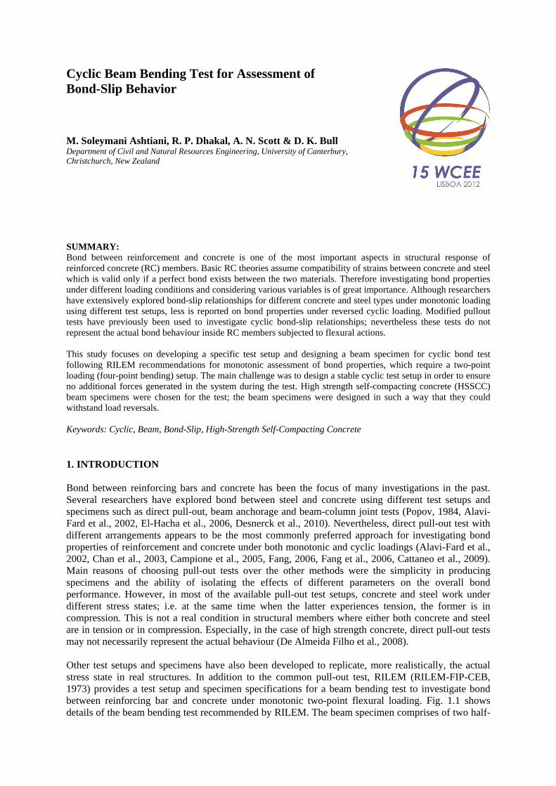
Figure 2.3.1. Schematic view and details of supports and loading points in monotonic test Nevertheless, the generation of both tensile and compressive forces in a cyclic test makes the monotonic test setup (previously mentioned) inapplicable, and a different test setup is required. Here too, the basics requirements are the same; i.e. the system should be stable and determinate at all time during the test without having extra internal or external constraints. It is obvious that a kind of clamping mechanism is necessary in order to hold the beam at both supports and loading points; so that, applying load reversal becomes feasible. Development of this part was performed through maintaining the same concept as shown in Fig. 2.3.1 and described before. The main difference here is the fact that all points (namely L1, L2, S1, and S2 in Fig. 2.3.1) should be clamped to the specimen. Therefore as opposed to the monotonic test setup, having 2 pins (one at support and the other at loading point) adds an undesirable constraint to the setup. Accordingly, one of the pins was replaced with a roller to maintain a determinate structure; as a result, 3 rollers and 1 pin makes the cyclic test setup stable and determinate. Fig. 2.3.2 shows a schematic view and details of the mentioned concept and requirements. In order to maintain uniform distribution of loads from the setup to the specimen, all steel plates sit on neoprene pads which in turn rest on the specimen surface.
Figure 2.3.2. Schematic view and details of supports and loading points in cyclic test In order to achieve the explained set of requirements for the supports and loading points of the cyclic test, special rollers (linear motion – LM) and precision made expandable pins were used (Fig. 2.3.2). The LM roller is a type of specially made unit which possesses a very high accuracy with high load and moment carrying capacity. Only the movement in the direction of LM rail is possible and all other translations and rotations are restricted. In other words, the LM roller is a fixed-roller support which almost provides a slack-free and friction-less rolling movement even under high axial and bending forces (Fig. 2.3.3).
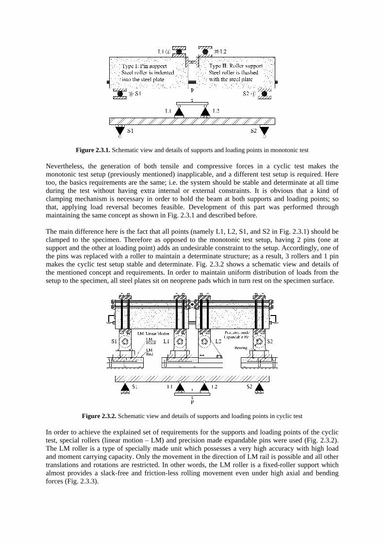
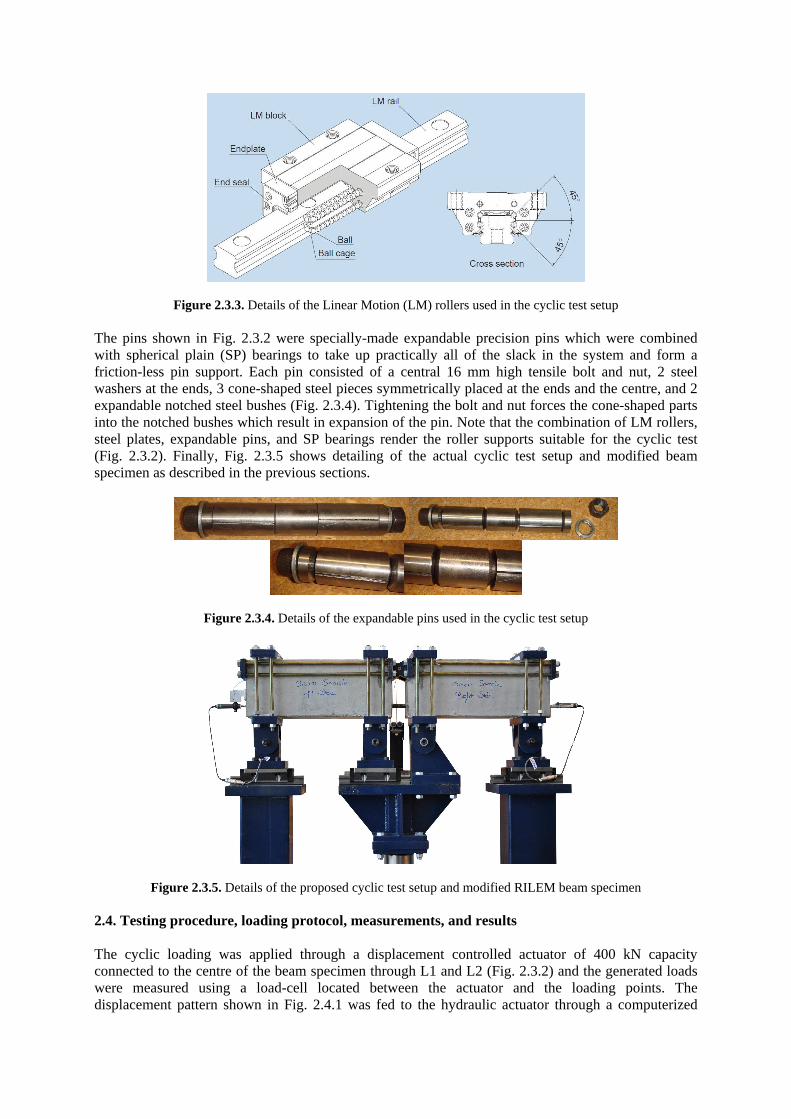
Figure 2.3.3. Details of the Linear Motion (LM) rollers used in the cyclic test setup The pins shown in Fig. 2.3.2 were specially-made expandable precision pins which were combined with spherical plain (SP) bearings to take up practically all of the slack in the system and form a friction-less pin support. Each pin consisted of a central 16 mm high tensile bolt and nut, 2 steel washers at the ends, 3 cone-shaped steel pieces symmetrically placed at the ends and the centre, and 2 expandable notched steel bushes (Fig. 2.3.4). Tightening the bolt and nut forces the cone-shaped parts into the notched bushes which result in expansion of the pin. Note that the combination of LM rollers, steel plates, expandable pins, and SP bearings render the roller supports suitable for the cyclic test (Fig. 2.3.2). Finally, Fig. 2.3.5 shows detailing of the actual cyclic test setup and modified beam specimen as described in the previous sections.
Figure 2.3.4. Details of the expandable pins used in the cyclic test setup
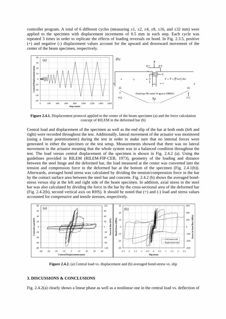
Figure 2.3.5. Details of the proposed cyclic test setup and modified RILEM beam specimen 2.4. Testing procedure, loading protocol, measurements, and results The cyclic loading was applied through a displacement controlled actuator of 400 kN capacity connected to the centre of the beam specimen through L1 and L2 (Fig. 2.3.2) and the generated loads were measured using a load-cell located between the actuator and the loading points. The displacement pattern shown in Fig. 2.4.1 was fed to the hydraulic actuator through a computerized
controller program. A total of 6 different cycles (measuring ±1, ±2, ±4, ±8, ±16, and ±32 mm) were applied to the specimen with displacement increments of 0.5 mm in each step. Each cycle was repeated 3 times in order to replicate the effects of loading reversals on bond. In Fig. 2.3.5, positive (+) and negative (-) displacement values account for the upward and downward movement of the center of the beam specimen, respectively.
-40
-30
-20
-10
0
10
20
30
40
0 200 400 600 800 1000 1200 1400 1600
Cen
tral
Dis
plac
emen
t (m
m)
Step counts
(a)
Figure 2.4.1. Displacement protocol applied to the center of the beam specimen (a) and the force calculation concept of RILEM in the deformed bar (b)
Central load and displacement of the specimen as well as the end slip of the bar at both ends (left and right) were recorded throughout the test. Additionally, lateral movement of the actuator was monitored (using a linear potentiometer) during the test in order to make sure that no internal forces were generated in either the specimen or the test setup. Measurements showed that there was no lateral movement in the actuator meaning that the whole system was in a balanced condition throughout the test. The load versus central displacement of the specimen is shown in Fig. 2.4.2 (a). Using the guidelines provided in RILEM (RILEM-FIP-CEB, 1973), geometry of the loading and distance between the steel hinge and the deformed bar, the load measured at the center was converted into the tension and compression force in the deformed bar at the bottom of the specimen (Fig. 2.4.1(b)). Afterwards, averaged bond stress was calculated by dividing the tension/compression force in the bar by the contact surface area between the steel bar and concrete. Fig. 2.4.2 (b) shows the averaged bond-stress versus slip at the left and right side of the beam specimen. In addition, axial stress in the steel bar was also calculated by dividing the force in the bar by the cross-sectional area of the deformed bar (Fig. 2.4.2(b), second vertical axis on RHS). It should be noted that (+) and (-) load and stress values accounted for compressive and tensile stresses, respectively.
-120
-90
-60
-30
0
30
60
90
120
-80
-60
-40
-20
0
20
40
60
80
-40 -30 -20 -10 0 10 20 30 40
For
ce in
Bar
(kN
)
Cen
tral
Loa
d (k
N)
Central Displacement (mm)
(a)
-600
-400
-200
0
200
400
600
-30
-20
-10
0
10
20
30
-2.5 -2 -1.5 -1 -0.5 0 0.5 1 1.5 2 2.5
Stre
ss in
Ste
el B
ar (M
Pa)
Bon
d St
ress
(MP
a)
Slip (mm)
Left hand sideRight hand side
(b)
Figure 2.4.2. (a) Central load vs. displacement and (b) averaged bond-stress vs. slip 3. DISCUSSIONS & CONCLUSIONS Fig. 2.4.2(a) clearly shows a linear phase as well as a nonlinear one in the central load vs. deflection of
the beam specimen. In the first 3 cycles (namely ±1, ±2 and ±4 mm) the specimen responded linearly, and the response deviated towards nonlinearity afterwards. For better illustration of the translation from the linear to nonlinear phase, Fig. 3.1 shows the central displacement versus slip relationship.
-10
-7.5
-5
-2.5
0
2.5
5
7.5
10
-0.5 -0.375 -0.25 -0.125 0 0.125 0.25 0.375 0.5
Cen
tral
Dis
plac
emen
t (m
m)
Slip (mm)
Left SlipRight Slip
(a)
-10
-7.5
-5
-2.5
0
2.5
5
7.5
10
-2.5 -2 -1.5 -1 -0.5 0 0.5 1 1.5 2 2.5
Cen
tral
Dis
plac
emen
t (m
m)
Slip (mm)
Left SlipRight Slip
(b)
Figure 3.1. Central deflection of the beam specimen against left and right slip for limited values Apparent deterioration of bond started at the initiation of ±8 mm displacement cycle in the left side of the specimen (Fig. 3.1(a)). By the time when the 3rd repetition of ±8 mm cycle finished, drastic deterioration in bond properties was observed with a slip value of over 2.5 mm (Fig. 3.1(b)). Note that the test setup and the specimen are not perfectly symmetrical; hence, only one side of the beam specimen (either left or right) will fail in pull-out after ultimate bond stress reaches. In this case and as mentioned before, the de-bonding of the deformed bar in the left side caused final failure of the specimen. Experimental results of this study have been compared with equivalent monotonic bond-slip tests performed by the authors (Soleymani Ashtiani et al., 2011). Details of the comparison are out of the scope of this paper, but the main findings of the comparison are summarized here. The ultimate stress levels obtained from both test methods were in reasonable agreement with more bond deterioration in case of the cyclic test; resulting in a slightly lower value of ultimate bond stress. In a further study, 18 modified beam specimens were fabricated and tested using the proposed test setup where concrete type, steel grade, bar diameter, bond length, and load type (monotonic and cyclic) were considered as variables. Complete details, specification, results, and discussions will soon be presented in the form of a follow up paper to support and extend the applicability of the proposed test setup. REFERENCES Alavi-Fard, M. and Marzouk, H. (2002). Bond behavior of high strength concrete under reversed pull-out cyclic
loading. Canadian Journal of Civil Engineering. 29:2, 191-200. Campione, G., Cucchiara, C., La Mendola, L. and Papia, A. (2005). Steel-concrete bond in lightweight fiber
reinforced concrete under monotonic and cyclic actions. Engineering Structures. 27:6, 881-890. Cattaneo, S. and Rosati, G. (2009). Bond between steel and self-consolidating concrete: Experiments and
modeling. ACI Structural Journal. 106:4, 540-550. Chan, Y.-W., Chen, Y.-S. and Liu, Y.-S. (2003). Development of bond strength of reinforcement steel in self-
consolidating concrete. ACI Structural Journal. 100:4, 490-498. Dancygier, A.N., Katz, A. and Wexler, U. (2010). Bond between deformed reinforcement and normal and high-
strength concrete with and without fibers. Materials and Structures/Materiaux et Constructions. 43, 839-856.
De Almeida Filho, F.M., El Debs, M.K. and El Debs, A.L.H.C. (2008). Bond-slip behavior of self-compacting concrete and vibrated concrete using pull-out and beam tests. Materials and Structures/Materiaux et Constructions. 41:6, 1073-1089.
Desnerck, P., De Schutter, G. and Taerwe, L. (2010). Bond behaviour of reinforcing bars in self-compacting concrete: Experimental determination by using beam tests. Materials and Structures/Materiaux et Constructions. 43, 53-62.
Dhakal, R.P. and Maekawa, K. (2002). Reinforcement stability and fracture of cover concrete in reinforced concrete members. Journal of Structural Engineering. 128:10, 1253-1262.
EFNARC (2002) Specification and guidelines for self-compacting concrete. EFNARC (2005) The european guidelines for self-compacting concrete specification, production and use. El-Hacha, R., El-Agroudy, H. and Rizkalla, S.H. (2006). Bond characteristics of high-strength steel
reinforcement. ACI Structural Journal. 103:6, 771-782. Fang, C.Q. (2006). Bond strength of corroded reinforcement under cyclic loading. Magazine of Concrete
Research. 58:7, 437-446. Fang, C.Q., Gylltoft, K., Lundgren, K. and Plos, M. (2006). Effect of corrosion on bond in reinforced concrete
under cyclic loading. Cement and Concrete Research. 36:3, 548-555. Popov, E.P. (1984). Bond and anchorage of reinforcing bars under cyclic loading. Journal of the American
Concrete Institute. 81:4, 340-349. RILEM-FIP-CEB (1973). Tentative recommendations, recommendations for reinforcing steel, bond test for
reinforcing steel: 1- beam test (7-ii-28 d) 2- pull-out test (7-ii-128). Materials and Structures. 6:2, 79-118.
Soleymani Ashtiani, M., Dhakal, R.P. and Scott, A.N. (2011). Bond properties of reinforcement in high-strength self-compacting concrete. Proceedings of the 9th Symposium on High Performance Concrete Design, Verification and Utilization. Rotorua, New Zealand.
Soleymani Ashtiani, M., Scott, A.N. and Dhakal, R.P. (2010). Mechanical properties of high-strength self-compacting concrete. Proceedings of the 21st Australasian Conference on the Mechanics of Structures and Materials. Melbourne, Australia. 827-832.
Su, N., Hsu, K.-C. and Chai, H.-W. (2001). A simple mix design method for self-compacting concrete. Cement and Concrete Research. 31:12, 1799-1807.