Page 1
Bluetooth SIG Proprietary and Confidential
Cycling Power Service (CPS) Bluetooth® Test Specification
Issued 2016-12-13
Document Number CPS.TS.1.1.2
Group Prepared by BTI
Feedback Email [email protected]
Abstract
This document defines test structures and procedures for conformance test of products implementing the Cycling
Power Service Specification.
Page 2
Cycling Power Service (CPS)
Bluetooth Test Specification
Bluetooth SIG Proprietary and Confidential Page 2 of 77
PS
.TS
.1.1
.2
Revision History
Revision History Date Comments
D0.9.4 2013-02-10 Version approved for prototyping.
1.0.0 2013-04-30 Release for publication.
1.0.1r1 2013-05-16 TSE 5176: Edits to the test procedure and pass verdict of
TP/SPE/BI-04-C.
1.0.1 2013-07-02 Prepare for Publication
1.0.2r1 2013-08-16
TCRL 2013-2
TSE 5184: Updated test procedure for TP/SPE/BI-02-C and
TP/SPE/BI-04-C.
1.0.2 2013-12-03 Prepare for Publication
1.1.0r00 2015-11-02
Modified for CPS version 1.1:
- Added tests for new feature ‘Start Enhanced Offset
Compensation’ (section 4.14)
- Updated Test Case Mapping Table.
1.1.0r01 2015-11-04 Minor editorial fixes in sections 4.14.1 and 4.14.2
1.1.0r02 2015-11-11 Added Pass/Fail Verdict Conventions according to applicable
test specification template;
1.1.0r03 2016-01-06 Converted to current document template.
1.1.0r04 2016-02-15 Minor editorial update, correct TCMT and sync up the
document with the changes from last IOP.
1.1.0r05 2016-04-05 Addressed BTI feedback
1.1.0r06 2016-04-08 Fixed indent on test case section heading
1.1.0 2016-04-19 Approved by BTI
1.1.0 2016-05-03 Specification version 1.1 adopted by the Bluetooth SIG BoD
1.1.0 2016-05-09 Prepared for publication
1.1.1r00 2016-05-23 Converted to new Test Case ID conventions as defined in
TSTO v4.1.
1.1.1 2016-07-13 Prepared for TCRL 2016-1 publication.
1.1.2r00 2016-08-17 TSE 7227: Updated Test Procedure (step 7a) and Pass verdict
for test case TP/SPE/BI-04-C.
1.1.2 2016-12-13 Approved by BTI. Prepared for TCRL 2016-2 publication.
Contributors
Name Company
Bob Hughes Intel
Guillaume Schatz Polar
Page 3
Cycling Power Service (CPS)
Bluetooth Test Specification
Bluetooth SIG Proprietary and Confidential Page 3 of 77
PS
.TS
.1.1
.2
Name Company
Leif-Alexandre Aschehoug Nordic Semiconductor
Jawid Mirani Cloud2GND
Page 4
Cycling Power Service (CPS)
Bluetooth Test Specification
Bluetooth SIG Proprietary and Confidential Page 4 of 77
PS
.TS
.1.1
.2
DISCLAIMER AND COPYRIGHT NOTICE
This disclaimer applies to all draft specifications and final specifications adopted by the Bluetooth SIG Board of Directors (both of which are hereinafter referred to herein as a Bluetooth “Specification”). Your use of this Specification in any way is subject to your compliance with all conditions of such use, and your acceptance of all disclaimers and limitations as to such use, contained in this Specification. Any user of this Specification is advised to seek appropriate legal, engineering or other professional advice regarding the use, interpretation or effect of this Specification on any matters discussed in this Specification.
Use of Bluetooth Specifications and any related intellectual property is governed by the Promoters Membership Agreement among
the Promoter Members and Bluetooth SIG (the “Promoters Agreement”), certain membership agreements between Bluetooth SIG
and its Adopter and Associate Members, including, but not limited to, the Membership Application, the Bluetooth Patent/Copyright
License Agreement and the Bluetooth Trademark License Agreement (collectively, the “Membership Agreements”) and the
Bluetooth Specification Early Adopters Agreements (1.2 Early Adopters Agreements) among Early Adopter members of the
unincorporated Bluetooth SIG and the Promoter Members (the “Early Adopters Agreement”). Certain rights and obligations of the
Promoter Members under the Early Adopters Agreements have been assigned to Bluetooth SIG by the Promoter Members.
Use of the Specification by anyone who is not a member of Bluetooth SIG or a party to an Early Adopters Agreement (each such
person or party, a “Member”) is prohibited. The use of any portion of a Bluetooth Specification may involve the use of intellectual
property rights ("IPR"), including pending or issued patents, or copyrights or other rights. Bluetooth SIG has made no search or
investigation for such rights and disclaims any undertaking or duty to do so. The legal rights and obligations of each Member are
governed by the applicable Membership Agreements, Early Adopters Agreement or Promoters Agreement. No license, express or
implied, by estoppel or otherwise, to any intellectual property rights are granted herein.
Any use of the Specification not in compliance with the terms of the applicable Membership Agreements, Early Adopters Agreement
or Promoters Agreement is prohibited and any such prohibited use may result in (i) termination of the applicable Membership
Agreements or Early Adopters Agreement and (ii) liability claims by Bluetooth SIG or any of its Members for patent, copyright and/or
trademark infringement claims permitted by the applicable agreement or by applicable law.
THE SPECIFICATION IS PROVIDED “AS IS” WITH NO WARRANTIES WHATSOEVER, INCLUDING ANY WARRANTY OF
MERCHANTABILITY, NONINFRINGEMENT, FITNESS FOR ANY PARTICULAR PURPOSE, SATISFACTORY QUALITY, OR
REASONABLE SKILL OR CARE, OR ANY WARRANTY ARISING OUT OF ANY COURSE OF DEALING, USAGE, TRADE
PRACTICE, PROPOSAL, SPECIFICATION OR SAMPLE.
Each Member hereby acknowledges that products equipped with the Bluetooth wireless technology ("Bluetooth Products") may be
subject to various regulatory controls under the laws and regulations applicable to products using wireless non licensed spectrum of
various governments worldwide. Such laws and regulatory controls may govern, among other things, the combination, operation,
use, implementation and distribution of Bluetooth Products. Examples of such laws and regulatory controls include, but are not
limited to, airline regulatory controls, telecommunications regulations, technology transfer controls and health and safety regulations.
Each Member is solely responsible for the compliance by their Bluetooth Products with any such laws and regulations and for
obtaining any and all required authorizations, permits, or licenses for their Bluetooth Products related to such regulations within the
applicable jurisdictions. Each Member acknowledges that nothing in the Specification provides any information or assistance in
connection with securing such compliance, authorizations or licenses. NOTHING IN THE SPECIFICATION CREATES ANY
WARRANTIES, EITHER EXPRESS OR IMPLIED, REGARDING SUCH LAWS OR REGULATIONS.
ALL LIABILITY, INCLUDING LIABILITY FOR INFRINGEMENT OF ANY INTELLECTUAL PROPERTY RIGHTS OR FOR
NONCOMPLIANCE WITH LAWS, RELATING TO USE OF THE SPECIFICATION IS EXPRESSLY DISCLAIMED. To the extent not
prohibited by law, in no event will Bluetooth SIG or its Members or their affiliates be liable for any damages, including without
limitation, lost revenue, profits, data or programs, or business interruption, or for special, indirect, consequential, incidental or
punitive damages, however caused and regardless of the theory of liability, arising out of or related to any furnishing, practicing,
modifying, use or the performance or implementation of the contents of this Specification, even if Bluetooth SIG or its Members or
their affiliates have been advised of the possibility of such damages. BY USE OF THE SPECIFICATION, EACH MEMBER
EXPRESSLY WAIVES ANY CLAIM AGAINST BLUETOOTH SIG AND ITS MEMBERS OR THEIR AFFILATES RELATED TO USE
OF THE SPECIFICATION.
If this Specification is an intermediate draft, it is for comment only. No products should be designed based on it except solely to
verify the prototyping specification at SIG sponsored IOP events and it does not represent any commitment to release or implement
any portion of the intermediate draft, which may be withdrawn, modified, or replaced at any time in the adopted Specification.
Bluetooth SIG reserves the right to adopt any changes or alterations to the Specification it deems necessary or appropriate.
Copyright © 2014–2016. The Bluetooth word mark and logos are owned by Bluetooth SIG, Inc. All copyrights in the
Bluetooth Specifications themselves are owned by Ericsson AB, Lenovo (Singapore) Pte. Ltd., Intel Corporation, Microsoft
Corporation, Motorola Mobility, LLC, Nokia Corporation and Toshiba Corporation. Other third-party brands and names are
the property of their respective owners.
Page 5
Cycling Power Service (CPS)
Bluetooth Test Specification
Bluetooth SIG Proprietary and Confidential Page 5 of 77
PS
.TS
.1.1
.2
Contents 1 Scope .................................................................................................................................................... 9
2 References, Definitions, and Abbreviations ................................................................................... 10
2.1 References ................................................................................................................................... 10
2.2 Definitions ..................................................................................................................................... 10
2.3 Abbreviations ................................................................................................................................ 10
3 Test Suite Structure (TSS) ................................................................................................................ 11
3.1 Overview ....................................................................................................................................... 11
3.2 Test Strategy ................................................................................................................................ 11
3.3 Test Groups .................................................................................................................................. 12
4 Test Cases .......................................................................................................................................... 13
4.1 Introduction ................................................................................................................................... 13
4.1.1 Test Case Identification Conventions .................................................................................... 13
4.1.2 Conformance ......................................................................................................................... 13
4.1.3 Pass/Fail Verdict Conventions .............................................................................................. 14
4.2 Setup Preambles .......................................................................................................................... 14
4.2.1 ATT Bearer on LE Transport ................................................................................................. 15
4.2.2 ATT Bearer on BR/EDR Transport ........................................................................................ 15
4.2.3 Cycling Power Control Point .................................................................................................. 15
4.2.4 Cycling Power Measurement Broadcast ............................................................................... 15
4.3 Service Definition .......................................................................................................................... 16
4.3.1 CPS/SEN/SD/BV-01-C [Service Definition over LE] ............................................................. 16
4.3.2 CPS/SEN/SD/BV-02-C [SDP Record] ................................................................................... 17
4.4 Characteristic Declaration ............................................................................................................ 18
4.4.1 CPS/SEN/DEC/BV-01-C [Characteristic Declaration - Cycling Power Feature] ................... 19
4.4.2 CPS/SEN/DEC/BV-02-C [Characteristic Declaration - Cycling Power Measurement] ......... 19
4.4.3 CPS/SEN/DEC/BV-03-C [Characteristic Declaration - Cycling Power Measurement (With
Broadcast Property Supported)] .......................................................................................................... 19
4.4.4 CPS/SEN/DEC/BV-04-C [Characteristic Declaration –Sensor Location].............................. 19
4.4.5 CPS/SEN/DEC/BV-05-C [Characteristic Declaration – Cycling Power Control Point] .......... 19
4.4.6 CPS/SEN/DEC/BV-06-C [Characteristic Declaration - Cycling Power Vector] ..................... 19
4.5 Characteristic Descriptors ............................................................................................................ 19
4.5.1 CPS/SEN/DES/BV-01-C [Cycling Power Measurement - Client Characteristic Configuration
Descriptor] ............................................................................................................................................ 20
Page 6
Cycling Power Service (CPS)
Bluetooth Test Specification
Bluetooth SIG Proprietary and Confidential Page 6 of 77
PS
.TS
.1.1
.2
4.5.2 CPS/SEN/DES/BV-02-C [Cycling Power Measurement - Server Characteristic Configuration
Descriptor] ............................................................................................................................................ 20
4.5.3 CPS/SEN/DES/BV-03-C [Cycling Power Control Point - Client Characteristic Configuration
Descriptor] ............................................................................................................................................ 20
4.5.4 CPS/SEN/DES/BV-04-C [Cycling Power Vector - Client Characteristic Configuration
Descriptor] ............................................................................................................................................ 20
4.6 Characteristic Read ...................................................................................................................... 20
4.6.1 CPS/SEN/CR/BV-01-C [Characteristic Read – Cycling Power Feature] .............................. 21
4.6.2 CPS/SEN/CR/BV-02-C [Characteristic Read - Sensor Location] ......................................... 21
4.7 Configure Indication and Notification ............................................................................................ 21
4.7.1 CPS/SEN/CON/BV-01-C [Configure Notification - Cycling Power Measurement] ................ 22
4.7.2 CPS/SEN/CON/BV-02-C [Configure Indication - Cycling Power Control Point] ................... 22
4.7.3 CPS/SEN/CON/BV-03-C [Configure Notification - Cycling Power Vector] ........................... 22
4.8 Configure Broadcast ..................................................................................................................... 22
4.8.1 CPS/SEN/COB/BV-01-C [Configure Broadcast - Cycling Power Measurement] ................. 23
4.9 Characteristic Notification ............................................................................................................. 23
4.9.1 CPS/SEN/CN/BV-01-C [Cycling Power Measurement Notifications] .................................... 23
4.9.2 CPS/SEN/CN/BV-02-C [Cycling Power Measurement Notifications – Pedal Power Balance]
25
4.9.3 CPS/SEN/CN/BV-03-C [Cycling Power Measurement Notifications – Accumulated Torque]
26
4.9.4 CPS/SEN/CN/BV-04-C [Cycling Power Measurement Notifications - Wheel Revolution Data]
27
4.9.5 CPS/SEN/CN/BV-05-C [Cycling Power Measurement Notifications – Forward Wheel
Revolution Data] .................................................................................................................................. 28
4.9.6 CPS/SEN/CN/BV-06-C [Cycling Power Measurement Notifications – Reverse Wheel
Revolution Data] .................................................................................................................................. 29
4.9.7 CPS/SEN/CN/BV-07-C [Cycling Power Measurement Notifications – Crank Revolution Data]
31
4.9.8 CPS/SEN/CN/BV-08-C [Cycling Power Measurement Notifications – Extreme Magnitude] 32
4.9.9 CPS/SEN/CN/BV-09-C [Cycling Power Measurement Notifications – Extreme Angles] ...... 33
4.9.10 CPS/SEN/CN/BV-10-C [Cycling Power Measurement Notifications – Top Dead Spot] ....... 34
4.9.11 CPS/SEN/CN/BV-11-C [Cycling Power Measurement Notifications – Bottom Dead Spot] .. 35
4.9.12 CPS/SEN/CN/BV-12-C [Cycling Power Measurement Notifications – Accumulated Energy]
36
4.9.13 CPS/SEN/CN/BV-13-C [Cycling Power Measurement Notifications – Offset Compensation
Indicator] .............................................................................................................................................. 38
Page 7
Cycling Power Service (CPS)
Bluetooth Test Specification
Bluetooth SIG Proprietary and Confidential Page 7 of 77
PS
.TS
.1.1
.2
4.9.14 CPS/SEN/CN/BV-14-C [Cycling Power Vector Notifications – Instantaneous Force
Magnitude Array] .................................................................................................................................. 39
4.9.15 CPS/SEN/CN/BV-15-C [Cycling Power Vector Notifications – Instantaneous Torque
Magnitude Array] .................................................................................................................................. 40
4.9.16 CPS/SEN/CN/BV-16-C [Cycling Power Vector Notifications – Crank Revolution Data] ....... 42
4.9.17 CPS/SEN/CN/BV-17-C [Cycling Power Vector Notifications – First Crank Measurement
Angle] 43
4.9.18 CPS/SEN/CN/BV-18-C [Cycling Power Vector Notifications – Instantaneous Measurement
Direction] .............................................................................................................................................. 44
4.9.19 CPS/SEN/CN/BI-01-C [Cycling Power Vector Notifications – Inappropriate Connection
Parameters] ......................................................................................................................................... 45
4.10 Service Procedures – Set Cumulative Value ............................................................................ 47
4.10.1 CPS/SEN/SPS/BV-01-C [Set Cumulative Value - Set to zero] ............................................. 47
4.10.2 CPS/SEN/SPS/BV-02-C [Set Cumulative Value - Set to non-zero] ...................................... 48
4.11 Service Procedure – Handle Server Parameters ...................................................................... 49
4.11.1 CPS/SEN/SPP/BV-01-C [Update Sensor Location] .............................................................. 49
4.11.2 CPS/SEN/SPP/BV-02-C [Request Supported Sensor Locations] ........................................ 50
4.11.3 CPS/SEN/SPP/BV-03-C [Set Crank Length] ........................................................................ 51
4.11.4 CPS/SEN/SPP/BV-04-C [Request Crank Length] ................................................................ 52
4.11.5 CPS/SEN/SPP/BV-05-C [Set Chain Length] ......................................................................... 53
4.11.6 CPS/SEN/SPP/BV-06-C [Request Chain Length] ................................................................. 54
4.11.7 CPS/SEN/SPP/BV-07-C [Set Chain Weight] ........................................................................ 55
4.11.8 CPS/SEN/SPP/BV-08-C [Request Chain Weight] ................................................................ 56
4.11.9 CPS/SEN/SPP/BV-09-C [Set Span Length] .......................................................................... 57
4.11.10 CPS/SEN/SPP/BV-10-C [Request Span Length] .............................................................. 58
4.11.11 CPS/SEN/SPP/BV-11-C [Request Factory Calibration Date] ........................................... 58
4.11.12 CPS/SEN/SPP/BV-12-C [Request Sampling Rate] ........................................................... 59
4.12 Service Procedure – Start Offset Compensation ...................................................................... 60
4.12.1 CPS/SEN/SPO/BV-01-C [Start Offset Compensation] ......................................................... 60
4.13 Service Procedure – Mask Cycling Power Measurement Characteristic Content .................... 61
4.13.1 CPS/SEN/SPM/BV-01-C [Mask Cycling Power Measurement Characteristic Content] ....... 61
4.13.2 CPS/SEN/SPM/BV-02-C [Mask Cycling Power Measurement Characteristic Content – Most
Recent Mask Value is not Cached] ...................................................................................................... 62
4.14 Service Procedure – Start Enhanced Offset Compensation .................................................... 64
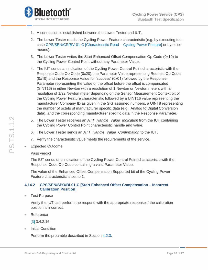
4.14.1 CPS/SEN/SPO/BV-02-C [Start Enhanced Offset Compensation] ........................................ 64
Page 8
Cycling Power Service (CPS)
Bluetooth Test Specification
Bluetooth SIG Proprietary and Confidential Page 8 of 77
PS
.TS
.1.1
.2
4.14.2 CPS/SEN/SPO/BI-01-C [Start Enhanced Offset Compensation – Incorrect Calibration
Position] 65
4.15 Service Procedure – General Error Handling ........................................................................... 66
4.15.1 CPS/SEN/SPE/BI-01-C [Op Code Not Supported] ............................................................... 66
4.15.2 CPS/SEN/SPE/BI-02-C [Invalid Parameter] .......................................................................... 67
4.15.3 CPS/SEN/SPE/BI-03-C [Client Characteristic Configuration Descriptor Improperly
Configured] .......................................................................................................................................... 68
4.15.4 CPS/SEN/SPE/BI-04-C [Procedure Already In Progress] .................................................... 68
4.15.5 CPS/SEN/SPE/BI-05-C [Cycling Power Control Point Procedure Timeout] ......................... 69
4.16 Characteristic Broadcast ........................................................................................................... 70
4.16.1 CPS/SEN/CB/BV-01-C [Cycling Power Measurement Broadcast] ....................................... 70
4.16.2 CPS/SEN/CB/BV-02-C [Cycling Power Measurement Broadcast - Stop Broadcasting when
Disconnected] ...................................................................................................................................... 72
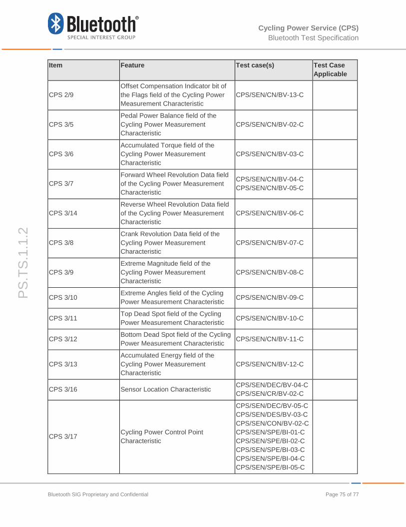
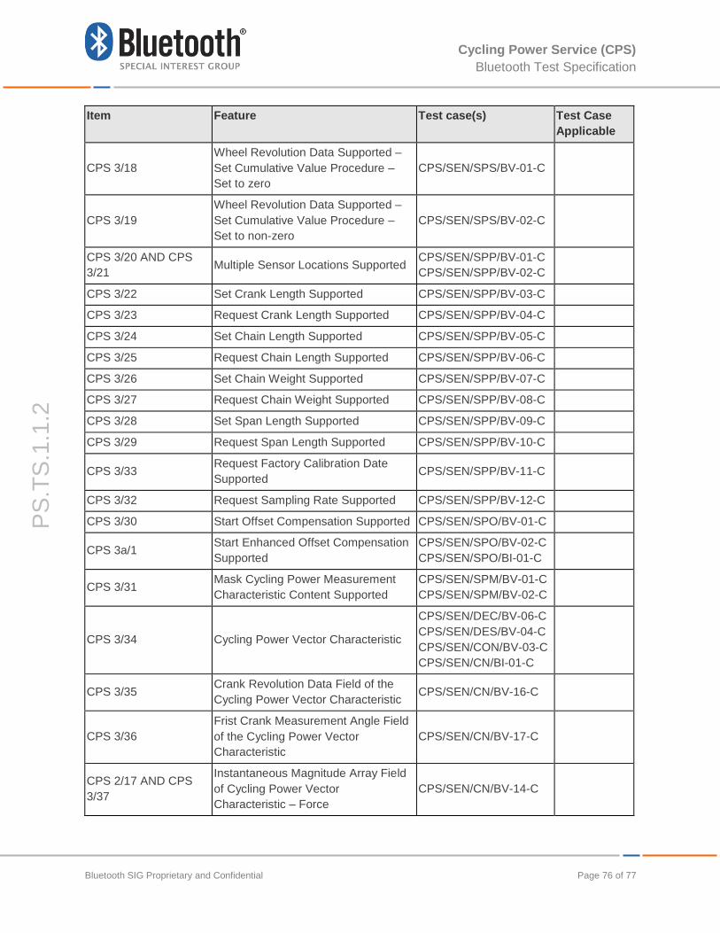
5 Test Case Mapping ............................................................................................................................ 74
Page 9
Cycling Power Service (CPS)
Bluetooth Test Specification
Bluetooth SIG Proprietary and Confidential Page 9 of 77
PS
.TS
.1.1
.2
1 Scope
This Bluetooth document contains the Test Suite Structure (TSS) and Test Cases (TC) to test
the Bluetooth Cycling Power Service Specification.
The objective of this test specification is to provide a basis for interoperability tests for Bluetooth
devices giving a high probability of air interface interoperability between different manufacturers’
Bluetooth devices.
Page 10
Cycling Power Service (CPS)
Bluetooth Test Specification
Bluetooth SIG Proprietary and Confidential Page 10 of 77
PS
.TS
.1.1
.2
2 References, Definitions, and Abbreviations
2.1 References
This Bluetooth document incorporates, by dated or undated reference, provisions from other
publications. These normative references are cited at the appropriate places in the text and the
publications are listed hereafter. For the purpose of this Bluetooth document, the definitions,
and abbreviations in [1], [2], and [3] apply.
[1] Test Strategy and Terminology Overview
[2] Bluetooth Core Specification v4.0 or later
[3] Cycling Power Service Specification v1.0 or later
[4] Cycling Power Service ICS, CPS.ICS
[5] GATT Test Specification, GATT.TS
[6] Characteristic and Descriptor descriptions are accessible via the Bluetooth SIG Assigned
Numbers.
[7] Cycling Power Service Implementation Extra Information for Test, IXIT
[8] Core Specification Supplement (CSS) v6
2.2 Definitions
For the purpose of this Bluetooth document, the definitions in [1] and [2] apply.
2.3 Abbreviations
For the purpose of this Bluetooth document, the abbreviations in [1] and [2] apply.
Page 11
Cycling Power Service (CPS)
Bluetooth Test Specification
Bluetooth SIG Proprietary and Confidential Page 11 of 77
PS
.TS
.1.1
.2
3 Test Suite Structure (TSS)
3.1 Overview
The Cycling Power Service requires the presence of GAP, SM, and GATT. This is illustrated in
Figure 3.1.
Cycling Power
Service
GATT
ATT GAP
L2CAP
Controller
SM(LE)
SDP(BR/EDR)
Figure 3.1: Cycling Power Service Test Model
3.2 Test Strategy
The test objectives are to verify the functionality of the Cycling Power Service within a Bluetooth
Host and enable interoperability between Bluetooth Hosts on different devices. The testing
approach is to cover mandatory and optional requirements in the service specification and to
match these to the support of the IUT as described in the ICS Proforma.
The test equipment shall provide an implementation of the Radio Controller and the parts of the
Host needed to perform the test cases defined in the Cycling Power Service Test Specification.
For some test cases, it is necessary to stimulate the IUT from an Upper Tester. In practice, this
could be implemented as a special test interface, an MMI, or another interface supported by the
IUT.
Page 12
Cycling Power Service (CPS)
Bluetooth Test Specification
Bluetooth SIG Proprietary and Confidential Page 12 of 77
PS
.TS
.1.1
.2
Additionally, the Cycling Power Measurement Broadcast feature, when supported by the IUT,
requires an additional test setup as specified by the preamble defined in Section 4.2.4 so the
Lower Tester can be used as a Broadcast Receiver.
The Cycling Power test suite contains Valid Behavior (BV) tests complemented with Invalid
Behavior (BI) tests where required. The test coverage mirrored in the test suite structure is the
result of a process that started with catalogued specification requirements that were logically
grouped and assessed for testability enabling coverage in defined test purposes.
3.3 Test Groups
The following test groups have been defined:
Service Definition
- Verify the service definition.
Characteristic Declaration
- Verify the presence and contents of characteristic declarations.
Characteristic Descriptors
- Verify the presence and contents of characteristic descriptors.
Characteristic Read
- Verify characteristics that support reading can be read. Verify the format and value of
characteristic values.
Configure Indication and Notification
- Verify characteristics can be configured for notification or for indication depending on
the characteristic requirements.
Configure Broadcast
- Verify characteristics can be configured for broadcast.
Characteristic Notification
- Verify characteristics which support notification can be notified.
Service Procedures
- Verify procedures as specified by the service such as set cumulative value, handle
server parameters, start offset compensation, mask cycling power measurement
characteristic content, start enhanced offset compensation, and general error
handling.
Characteristic Broadcast
- Verify characteristics which support broadcast can be broadcasted by the IUT.
Page 13
Cycling Power Service (CPS)
Bluetooth Test Specification
Bluetooth SIG Proprietary and Confidential Page 13 of 77
PS
.TS
.1.1
.2
4 Test Cases
4.1 Introduction
4.1.1 Test Case Identification Conventions
Test cases shall be assigned unique identifiers per the conventions in [1]. The convention used
here is <spec abbreviation>/<IUT role>/<class>/<xx>-<nn>-<y>.
Test group abbreviations for class, feature, function, sub-function or capability (as applicable to
this test specification) are defined in Table 4.1.
Identifier Class identifier <class>
CPS Cycling Power Service
SEN Sensor Role
SD Service Definition
DEC Characteristic Declaration
DES Characteristic Descriptors
CR Characteristic Read
CON Configure Indication or Notification
COB Configure Broadcast
CN Characteristic Notification
SPS Service Procedures – Set Cumulative Value
SPP Service Procedures – Handle Server Parameters
SPO Service Procedure – Start Offset Compensation
Service Procedure – Start Enhanced Offset Compensation
SPM Service Procedure – Mask Cycling Power Measurement
Characteristic Content
SPE Service Procedure – Error Handling
CB Characteristic Broadcast
Table 4.1: TP Class Naming Convention
4.1.2 Conformance
When conformance is claimed, all capabilities indicated as mandatory for this Specification shall
be supported in the specified manner (process-mandatory). This also applies for all optional and
conditional capabilities for which support is indicated. All mandatory capabilities and optional
and conditional capabilities for which support is indicated are subject to verification as part of
the Bluetooth certification program.
Page 14
Cycling Power Service (CPS)
Bluetooth Test Specification
Bluetooth SIG Proprietary and Confidential Page 14 of 77
PS
.TS
.1.1
.2
The Bluetooth Qualification Program may employ tests to verify implementation robustness. The
level of implementation robustness that is verified varies from one Specification to another and
may be revised for cause based on interoperability issues found in the market.
Such tests may verify:
that claimed capabilities may be used in any order and any number of repetitions that is
not excluded by the Specification, OR
that capability enabled by the implementations are sustained over durations expected by
the use case, OR
that the implementation gracefully handles any quantity of data expected by the use
case, OR
that the implementation gracefully rejects any attempt to exercise capabilities which
were declared as not supported. Graceful rejection means that the implementation
demonstrates uninterrupted conformance to the specification immediately after rejecting
such attempts without any need to be externally reset or adjusted, OR
that in cases where more than one valid interpretation of the Specification exist, the
implementation complies with at least one interpretation and gracefully handles other
interpretations, OR
that the implementation is immune to attempted security exploits.
A single execution of each of the required tests is required in order to constitute a pass verdict.
However, it is noted that in order to provide a foundation for interoperability, it is necessary that
a qualified implementation consistently and repeatedly passes any of the applicable tests.
In any case, where a member finds an issue with the Test Plan Generator, the Test Case as
described in the Test Specification, or with the Test System utilized, the Member is required to
notify the responsible party via an errata request such that the issue may be addressed.
4.1.3 Pass/Fail Verdict Conventions
Each test case has an Expected Outcome section, which outlines all the detailed pass criteria
conditions that shall be met by the IUT to merit a Pass Verdict.
The convention in this test specification is that, unless there is a specific set of fail conditions
outlined in the test case, then the IUT fails the test case as soon one of the pass criteria
conditions cannot be met and in case this occurs the outcome of the test shall be the Fail
Verdict.
4.2 Setup Preambles
The procedures defined in this section are provided for information, as they are used by test
equipment in achieving the initial conditions in certain tests.
Page 15
Cycling Power Service (CPS)
Bluetooth Test Specification
Bluetooth SIG Proprietary and Confidential Page 15 of 77
PS
.TS
.1.1
.2
4.2.1 ATT Bearer on LE Transport
Follow the preamble procedure described in [5] Section 4.2.1.2 with the IUT operating in the
Peripheral role.
4.2.2 ATT Bearer on BR/EDR Transport
Follow the preamble procedure described in [5] Section 4.2.1.1.
4.2.3 Cycling Power Control Point
Follow this preamble procedure to enable the IUT for use with the Cycling Power Control Point.
Establish an ATT Bearer connection between the Lower Tester and IUT as described in Section
4.2.1 if using an LE transport or 4.2.2 if using a BR/EDR transport.
The handle of the Cycling Power Measurement, the Cycling Power Feature, the Sensor
Location, the Cycling Power Control Point and Cycling Power Vector characteristics have been
previously discovered by the Lower Tester during the test procedure in Section 4.4 or is known
to the Lower Tester by other means.
The handle of the Client Characteristic Configuration descriptor of the Cycling Power
Measurement characteristic and Cycling Power Control Point characteristic has been previously
discovered by the Lower Tester during the test procedure in Section 4.5 or is known to the
Lower Tester by other means.
If the IUT requires bonding, then the Lower Tester performs a bonding procedure.
The IUT configures the Cycling Power Control Point characteristic for indications, and if the test
case requires notifications of the Cycling Power Measurement characteristic or the Cycling
Power Vector characteristic, then the IUT configures these characteristics for notifications.
Those configurations may happen in any order.
4.2.4 Cycling Power Measurement Broadcast
Follow this preamble procedure to enable the IUT for use with the Cycling Power Measurement
Broadcast feature.
Establish an ATT Bearer connection between the Lower Tester and IUT as described in Section
4.2.1 if using an LE transport or 4.2.2 if using a BR/EDR transport.
The handle of the Cycling Power Measurement characteristic has been previously discovered
by the Lower Tester during the test procedure in Section 4.4 or is known to the Lower Tester by
other means.
The handles of the Server Characteristic Configuration descriptor of the Cycling Power
Measurement characteristic have been previously discovered by Lower Tester during the test
procedure in Section 4.5 or is known to the Lower Tester by other means.
If the IUT requires bonding, then the Lower Tester performs a bonding procedure.
The Lower Tester configures the Cycling Power Measurement characteristic for broadcast.
Page 16
Cycling Power Service (CPS)
Bluetooth Test Specification
Bluetooth SIG Proprietary and Confidential Page 16 of 77
PS
.TS
.1.1
.2
4.3 Service Definition
Verify the service definition.
4.3.1 CPS/SEN/SD/BV-01-C [Service Definition over LE]
Test Purpose
Verify the IUT has an instantiation of the Cycling Power Service as either a primary service
or a secondary service. This test case only applies when using the LE transport.
Reference
[3] 2
Initial Condition
Establish an ATT Bearer connection between the Lower Tester and IUT as described in
Section 4.2.1.
Test Procedure
The Lower Tester sends an ATT_Find_By_Type_Value_Request (0x0001, 0xFFFF) to the
IUT, with type set to «Primary Service» and Value set to «Cycling Power Service». Verify
one attribute handle range is returned, containing the starting handle and the ending handle
of the service definition.
If no instances of Cycling Power Service as a primary service are found, the Lower Tester
sends an ATT_Find_By_Type_Value_Request (0x0001, 0xFFFF) to the IUT, with type set to
«Secondary Service» and Value set to the UUID for «Cycling Power Service». Verify one
attribute handle range is returned, containing the starting handle and the ending handle of
the service definition.
Page 17
Cycling Power Service (CPS)
Bluetooth Test Specification
Bluetooth SIG Proprietary and Confidential Page 17 of 77
PS
.TS
.1.1
.2
ATT_Find_By_Type_Response
(Code = 0x07, handle range)
Upper TesterIUTLower Tester
ATT Bearer established over selected transport (4.2).
ATT_MTU has been exchanged between IUT and test system.
ATT_Find_By_Type_Value_Request
(Code = 0x06, 0x0001, 0xFFFF,
<Primary Service>,
<Cycling Power Service>)
ALT 1:
primary service found
ALT 2:
secondary service foundATT_Find_By_Type_Value_Request
(Code = 0x06, 0x0001, 0xFFFF,
<Secondary Service>,
<Cycling Power Service>)
ATT_Find_By_Type_Response
(Code = 0x07, handle range)
ATT_Error_Response
(Code = 0x01, <AttributeNotFound>)
Figure 4.1: Service Definition over LE
Expected Outcome
Pass verdict
One attribute handle range is returned (either as a primary service or a secondary service),
containing the starting handle and the ending handle of the service definition. The Attribute
Type in that service declaration is either «Primary Service» or «Secondary Service».
4.3.2 CPS/SEN/SD/BV-02-C [SDP Record]
Test Purpose
Verify the SDP Record for the Cycling Power Service. This test case only applies when
using the BR/EDR transport.
Reference
[3] 2, 4
Initial Condition
An ACL connection over BR/EDR is established between the Lower Tester and IUT.
Test Procedure
The Lower Tester establishes an SDP connection to the IUT.
The Lower Tester sends SDP requests to retrieve all attributes of the SDP record for the
Cycling Power.
Page 18
Cycling Power Service (CPS)
Bluetooth Test Specification
Bluetooth SIG Proprietary and Confidential Page 18 of 77
PS
.TS
.1.1
.2
Expected Outcome
Pass verdict
The SDP record for the service is found.
All attributes, which are mandatory for the service, are present in the SDP record.
The values of all attributes in the SDP record meet the requirements of the service.
The GATT Start Handle and GATT End Handle parameters in the SDP record match the
start handle and end handle of the service.
4.4 Characteristic Declaration
This test group contains test cases to verify that the characteristic property field of the
characteristic declaration meets the requirements of the service. The verification is performed
one property at a time, as enumerated in the test cases in Table 4.2, using this generic test
procedure.
Reference
[3] 3
Initial Condition
The handle range of the service has been previously discovered by the Lower Tester in test
case CPS/SEN/SD/BV-01-C [Service Definition over LE] if using an LE transport or
CPS/SEN/SD/BV-02-C [SDP Record] if using a BR/EDR transport.
Establish an ATT Bearer connection between the Lower Tester and IUT as described in
Section 4.2.1 if using an LE transport or Section 4.2.2 if using a BR/EDR transport.
Test Procedure
The following test procedure applies to the test cases listed in Table 4.2:
Discover all characteristics of the service by executing the test procedure of GATT test case
GATT/SR/GAD/BV-04-C and GATT/SR/GAD/BV-05-C in [5].
For a discovered characteristic that is listed in Table 4.2, verify the characteristic properties
field of the characteristic declaration meets the requirements of the service.
Expected Outcome
The following pass and fail verdicts apply to the test cases listed in Table 4.2.
Pass verdict
The characteristic is discovered and the characteristic properties field of the characteristic
declaration meets the requirements of the service.
Page 19
Cycling Power Service (CPS)
Bluetooth Test Specification
Bluetooth SIG Proprietary and Confidential Page 19 of 77
PS
.TS
.1.1
.2
Test Case Characteristic Properties Value (Requirements)
4.4.1 CPS/SEN/DEC/BV-01-C [Characteristic Declaration - Cycling Power Feature]
0x02 ([3] Table 3.1)
4.4.2 CPS/SEN/DEC/BV-02-C [Characteristic Declaration - Cycling Power Measurement]
0x10 ([3] Table 3.1)
4.4.3 CPS/SEN/DEC/BV-03-C [Characteristic Declaration - Cycling Power Measurement (With Broadcast Property Supported)]
0x11 ([3] Table 3.1)
4.4.4 CPS/SEN/DEC/BV-04-C [Characteristic Declaration –Sensor Location]
0x02 ([3] Table 3.1)
4.4.5 CPS/SEN/DEC/BV-05-C [Characteristic Declaration – Cycling Power Control Point]
0x28 ([3] Table 3.1)
4.4.6 CPS/SEN/DEC/BV-06-C [Characteristic Declaration - Cycling Power Vector]
0x10 ([3] Table 3.1)
Table 4.2: Characteristic Declaration Test Cases
4.5 Characteristic Descriptors
This test group contains test cases to verify that the characteristic descriptors meet the
requirements of the service. The verification is done one descriptor at a time, as enumerated in
the test cases in Table 4.3, using this generic test procedure.
Reference
[3] 3
Initial Condition
The handle range of each characteristic referenced in the test cases below has been
previously discovered by the Lower Tester during the test procedure in Section 4.4 or is
known to the Lower Tester by other means.
Establish an ATT Bearer connection between the Lower Tester and IUT as described in
Section 4.2.1 if using an LE transport or Section 4.2.2 if using a BR/EDR transport.
Test Procedure
The following test procedure applies to the test cases listed in Table 4.3:
Discover all characteristic descriptors of the characteristic by executing the test
procedure of GATT test case GATT/SR/GAD/BV-06-C in [5] using the handle range of
the characteristic. The IUT returns, at least, one handle-UUID pair.
If the UUID in a handle-UUID pair is for a characteristic descriptor referenced in a test
case below, read the characteristic descriptor by executing the test procedure of GATT
test case GATT/SR/GAR/BV-06-C in [5].
Page 20
Cycling Power Service (CPS)
Bluetooth Test Specification
Bluetooth SIG Proprietary and Confidential Page 20 of 77
PS
.TS
.1.1
.2
Verify the value of the characteristic descriptor meets the requirements of the service.
Expected Outcome
The following pass and fail verdicts apply to the test cases listed in Table 4.3:
Pass verdict
The characteristic descriptor is discovered, the characteristic descriptor is read, and the
value of the characteristic descriptor meets the requirements of the service.
Test Case Value (Requirements)
4.5.1 CPS/SEN/DES/BV-01-C [Cycling Power Measurement - Client Characteristic Configuration Descriptor]
0x0000 or 0x0001 ([3] 3)
4.5.2 CPS/SEN/DES/BV-02-C [Cycling Power Measurement - Server Characteristic Configuration Descriptor]
0x0000 or 0x0001 ([3] 3)
4.5.3 CPS/SEN/DES/BV-03-C [Cycling Power Control Point - Client Characteristic Configuration Descriptor]
0x0000 or 0x0002 ([3] 3)
4.5.4 CPS/SEN/DES/BV-04-C [Cycling Power Vector - Client Characteristic Configuration Descriptor]
0x0000 or 0x0001 ([3] 3)
Table 4.3: Characteristic Descriptor Test Cases
4.6 Characteristic Read
This test group contains test cases to read and verify that the characteristic values required by
the service are compliant. The verification is done one value at a time, as enumerated in the test
cases in Table 4.4, using this generic test procedure.
Reference
[3] 3.1.1 and 3.3.1
Initial Condition
The handle of each characteristic value referenced in the test cases below has been
previously discovered by the Lower Tester during the test procedure in Section 4.4 or is
known to the Lower Tester by other means.
If the IUT requires a bonding procedure then perform a bonding procedure.
Establish an ATT Bearer connection between the Lower Tester and IUT as described in
Section 4.2.1 if using an LE transport or Section 4.2.2 if using a BR/EDR transport.
If IUT permissions for the characteristic require a specific security mode or security level,
establish a connection meeting those requirements.
Test Procedure
Page 21
Cycling Power Service (CPS)
Bluetooth Test Specification
Bluetooth SIG Proprietary and Confidential Page 21 of 77
PS
.TS
.1.1
.2
The following test procedure applies to the test cases listed in Table 4.4:
Read the characteristic value by executing the test procedure of GATT test case GATT/SR/
GAR/BV-01-C in [5].
Verify the characteristic value meets the requirements of the service.
Expected Outcome
The following pass and fail verdicts apply to the test cases listed in Table 4.4:
Pass verdict
The characteristic is successfully read and the characteristic value meets the requirements
of the service.
Test Case Value (Requirements)
4.6.1 CPS/SEN/CR/BV-01-C [Characteristic Read – Cycling Power Feature]
4 octets with RFU bits set to 0. ([3] 3.1.1)
4.6.2 CPS/SEN/CR/BV-02-C [Characteristic Read - Sensor Location]
1 octet with value other than RFU
range. ([3] 3.3.1)
Table 4.4: Characteristic Read Value Test Cases
4.7 Configure Indication and Notification
This test group contains test cases to verify compliant operation in response to enable and
disable characteristic indication or notification. The verification is done one value at a time, as
enumerated in the test cases in Table 4.5, using this generic test procedure.
Reference
[3] 3.2, 3.4 and 3.5
Initial Condition
The handle of each characteristic value referenced in the test cases below has been
previously discovered by the Lower Tester during the test procedure in Section 4.4 or is
known to the Lower Tester by other means.
The handle of the Client Characteristic Configuration descriptor of each characteristic
referenced in the test cases below has been previously discovered by the Lower Tester
during the test procedure in Section 4.5 or is known to the Lower Tester by other means.
If the IUT requires a bonding procedure then perform a bonding procedure.
Establish an ATT Bearer connection between the Lower Tester and IUT as described in
Section 4.2.1 if using an LE transport or Section 4.2.2 if using a BR/EDR transport.
If IUT permissions for the characteristic descriptor require a specific security mode or
security level, establish a connection meeting those requirements.
Test Procedure
Page 22
Cycling Power Service (CPS)
Bluetooth Test Specification
Bluetooth SIG Proprietary and Confidential Page 22 of 77
PS
.TS
.1.1
.2
The following test procedure applies to the test cases listed in Table 4.5:
Disable indication or notification by writing value 0x0000 to the Client Characteristic
Configuration descriptor of the characteristic using the test procedure of GATT test case
GATT/SR/GAW/BV-08-C in [5].
If the test case is for notification, enable notification by writing value 0x0001 to the Client
Characteristic Configuration descriptor of the characteristic.
Otherwise, if the test case is for indication, enable indication by writing value 0x0002 to the
Client Characteristic Configuration descriptor of the characteristic.
The Lower Tester reads the value of the Client Characteristic Configuration descriptor.
Expected Outcome
The following pass and fail verdicts apply to the test cases listed in Table 4.5:
Pass verdict
The characteristic descriptor is successfully written and the value returned when read is
consistent with the value written.
Test Case Requirements
4.7.1 CPS/SEN/CON/BV-01-C [Configure Notification - Cycling Power Measurement]
0x0001 ([3] 3.2)
4.7.2 CPS/SEN/CON/BV-02-C [Configure Indication - Cycling Power Control Point]
0x0002 ([3] 3.4)
4.7.3 CPS/SEN/CON/BV-03-C [Configure Notification - Cycling Power Vector]
0x0001 ([3] 3.5)
Table 4.5: Configure Indication and Notification Test Cases
4.8 Configure Broadcast
This test group contains test cases to verify compliant operation in response to enable and
disable characteristic broadcast. The verification is done one value at a time, as enumerated in
the test cases in Table 4.6, using this generic test procedure.
Reference
[3] 3.2
Initial Condition
The handle of each characteristic value referenced in the test cases below has been
previously discovered by the Lower Tester during the test procedure in Section 4.4 or is
known to the Lower Tester by other means.
The handle of the Server Characteristic Configuration descriptor of each characteristic
referenced in the test cases below has been previously discovered by the Lower Tester
during the test procedure in Section 4.5 or is known to the Lower Tester by other means.
Page 23
Cycling Power Service (CPS)
Bluetooth Test Specification
Bluetooth SIG Proprietary and Confidential Page 23 of 77
PS
.TS
.1.1
.2
If the IUT requires a bonding procedure then perform a bonding procedure.
Establish an ATT Bearer connection between the Lower Tester and IUT as described in
Section 4.2.1 if using an LE transport or Section 4.2.2 if using a BR/EDR transport.
If IUT permissions for the characteristic descriptor require a specific security mode or
security level, establish a connection meeting those requirements.
Test Procedure
The following test procedure applies to the test cases listed in Table 4.6:
Disable broadcast by writing value 0x0000 to the Server Characteristic Configuration
descriptor of the characteristic using the test procedure of GATT test case
GATT/SR/GAW/BV-08-C in [5].
Enable broadcast by writing value 0x0001 to the Server Characteristic Configuration
descriptor of the characteristic.
The Lower Tester reads the value of the Server Characteristic Configuration descriptor.
Expected Outcome
The following pass and fail verdicts apply to the test cases listed in Table 4.6:
Pass verdict
The characteristic descriptor is successfully written and the value returned when read is
consistent with the value written.
Test Case Requirements
4.8.1 CPS/SEN/COB/BV-01-C [Configure Broadcast - Cycling Power Measurement]
0x0001 ([3] 3.2.2.2)
Table 4.6: Configure Broadcast Test Cases
4.9 Characteristic Notification
4.9.1 CPS/SEN/CN/BV-01-C [Cycling Power Measurement Notifications]
Test Purpose
Verify the IUT can send notifications of the Cycling Power Measurement characteristic that
include the mandatory fields (e.g. the Flags field and the Instantaneous Power field).
Reference
[3] 3.2
Initial Condition
If the IUT requires a bonding procedure then perform a bonding procedure.
Page 24
Cycling Power Service (CPS)
Bluetooth Test Specification
Bluetooth SIG Proprietary and Confidential Page 24 of 77
PS
.TS
.1.1
.2
The Cycling Power Measurement characteristic is configured for notification.
If desired, establish an ATT Bearer connection between the Lower Tester and IUT as
described in Section 4.2.1 if using an LE transport or Section 4.2.2 if using a BR/EDR
transport.
If IUT permissions for the Cycling Power Measurement characteristic require a specific
security mode or security level, establish a connection meeting those requirements.
Test Procedure
1. Perform an action on the IUT that will induce it, once connected, to send notifications of
the Cycling Power Measurement characteristic along with the Flags field and the
Instantaneous Power field.
2. A connection is established between the Lower Tester and IUT meeting the security
requirements of the IUT, if not already done so prior to step 1.
3. The Lower Tester reads the Cycling Power Feature characteristic (e.g. by executing test
case CPS/SEN/CR/BV-01-C [Characteristic Read – Cycling Power Feature] or by other
means).
4. The Lower Tester receives one or more ATT_Handle_Value_Notification from the IUT
containing the Cycling Power Measurement characteristic handle and value along with
the Flags field and the Instantaneous Power field.
5. Verify the characteristic value meets the requirements of the service.
6. Repeat steps 4-5 until the Lower Tester receives one or more additional notifications.
7. The Lower Tester configures the Cycling Power Measurement characteristic to disable
notifications.
8. Repeat steps 1-2 with notifications disabled.
9. Verify the Lower Tester does not receive an ATT_Handle_Value_Notification from the
IUT containing the Cycling Power Measurement characteristic.
Expected Outcome
Pass verdict
The IUT sends two or more notifications of the Cycling Power Measurement characteristic
along with the Flags field and the Instantaneous Power field.
The Cycling Power Measurement characteristics contain at least the Flags field and the
Instantaneous Power field.
The value of each field of the characteristic meets the requirements of the service.
The IUT stops sending notifications of the Cycling Power Measurement characteristic after
the Lower Tester configures the characteristic to disable notifications.
In all cases, ensure that the RFU bits of the Flags field are set to zero.
Page 25
Cycling Power Service (CPS)
Bluetooth Test Specification
Bluetooth SIG Proprietary and Confidential Page 25 of 77
PS
.TS
.1.1
.2
4.9.2 CPS/SEN/CN/BV-02-C [Cycling Power Measurement Notifications – Pedal Power Balance]
Test Purpose
Verify the IUT can send notifications of the Cycling Power Measurement characteristic that
include Pedal Power Balance value.
Reference
[3] 3.2.1.3
Initial Condition
If the IUT requires a bonding procedure then perform a bonding procedure.
The Cycling Power Measurement characteristic is configured for notification.
If desired, establish an ATT Bearer connection between the Lower Tester and IUT as
described in Section 4.2.1 if using an LE transport or Section 4.2.2 if using a BR/EDR
transport.
If IUT permissions for the Cycling Power Measurement characteristic require a specific
security mode or security level, establish a connection meeting those requirements.
Test Procedure
1. Perform an action on the IUT that will induce it, once connected, to send notifications of
the Cycling Power Measurement characteristic along with Pedal Power Balance field.
2. A connection is established between the Lower Tester and IUT meeting the security
requirements of the IUT, if not already done so prior to step 1.
3. The Lower Tester reads the Cycling Power Feature characteristic (e.g. by executing test
case CPS/SEN/CR/BV-01-C [Characteristic Read – Cycling Power Feature] or by other
means).
4. The Lower Tester receives one or more ATT_Handle_Value_Notification from the IUT
containing the Cycling Power Measurement characteristic handle and value along with
the Pedal Power Balance field.
5. Verify the characteristic value meets the requirements of the service.
6. Repeat steps 4-5 until the Lower Tester receives one or more additional notifications.
7. The Lower Tester configures the Cycling Power Measurement characteristic to disable
notifications.
Expected Outcome
Pass verdict
The IUT sends two or more notifications of the Cycling Power Measurement characteristic
and, at least, one includes the Pedal Power Balance value with the appropriate flag set in
the Flags field.
Page 26
Cycling Power Service (CPS)
Bluetooth Test Specification
Bluetooth SIG Proprietary and Confidential Page 26 of 77
PS
.TS
.1.1
.2
The value of each field of the characteristic meets the requirements of the service.
The value of the Pedal Power Balance Supported bit of the Cycling Power Feature
characteristic is set to 1.
In all cases, ensure that the RFU bits of the Flags field are set to zero.
4.9.3 CPS/SEN/CN/BV-03-C [Cycling Power Measurement Notifications – Accumulated Torque]
Test Purpose
Verify the IUT can send notifications of the Cycling Power Measurement characteristic that
include Accumulated Torque value.
Reference
[3] 3.2.1.4
Initial Condition
If the IUT requires a bonding procedure then perform a bonding procedure.
The Cycling Power Measurement characteristic is configured for notification.
If desired, establish an ATT Bearer connection between the Lower Tester and IUT as
described in Section 4.2.1 if using an LE transport or Section 4.2.2 if using a BR/EDR
transport.
If IUT permissions for the Cycling Power Measurement characteristic require a specific
security mode or security level, establish a connection meeting those requirements.
Test Procedure
1. Perform an action on the IUT that will induce it, once connected, to send notifications of
the Cycling Power Measurement characteristic along with Accumulated Torque field.
2. A connection is established between the Lower Tester and IUT meeting the security
requirements of the IUT, if not already done so prior to step 1.
3. The Lower Tester reads the Cycling Power Feature characteristic (e.g. by executing test
case CPS/SEN/CR/BV-01-C [Characteristic Read – Cycling Power Feature] or by other
means).
4. The Lower Tester receives one or more ATT_Handle_Value_Notification from the IUT
containing the Cycling Power Measurement characteristic handle and value along with
the Accumulated Torque field.
5. Verify the characteristic value meets the requirements of the service.
6. Repeat steps 4-5 until the Lower Tester receives one or more additional notifications.
7. The Lower Tester configures the Cycling Power Measurement characteristic to disable
notifications.
Page 27
Cycling Power Service (CPS)
Bluetooth Test Specification
Bluetooth SIG Proprietary and Confidential Page 27 of 77
PS
.TS
.1.1
.2
Expected Outcome
Pass verdict
The IUT sends two or more notifications of the Cycling Power Measurement characteristic
and at least, one includes the Accumulated Torque value with the appropriate flag set in the
Flags field.
The value of each field of the characteristic meets the requirements of the service.
The value of the Accumulated Torque Supported bit of the Cycling Power Feature
characteristic is set to 1.
In all cases, ensure that the RFU bits of the Flags field are set to zero.
4.9.4 CPS/SEN/CN/BV-04-C [Cycling Power Measurement Notifications - Wheel Revolution Data]
Test Purpose
Verify the IUT can send notifications of the Cycling Power Measurement characteristic that
include Cumulative Wheel Revolutions and Last Wheel Event Time values.
Reference
[3] 3.2.1.5
Initial Condition
If the IUT requires a bonding procedure then perform a bonding procedure.
The Cycling Power Measurement characteristic is configured for notification.
If desired, establish an ATT Bearer connection between the Lower Tester and IUT as
described in Section 4.2.1 if using an LE transport or Section 4.2.2 if using a BR/EDR
transport.
If IUT permissions for the Cycling Power Measurement characteristic require a specific
security mode or security level, establish a connection meeting those requirements.
Test Procedure
1. Perform an action on the IUT that will induce it, once connected, to send notifications of
the Cycling Power Measurement characteristic along with Cumulative Wheel
Revolutions and Last Wheel Event Time fields.
2. A connection is established between the Lower Tester and IUT meeting the security
requirements of the IUT, if not already done so prior to step 1.
3. The Lower Tester reads the Cycling Power Feature characteristic (e.g. by executing test
case CPS/SEN/CR/BV-01-C [Characteristic Read – Cycling Power Feature] or by other
means).
4. The Lower Tester receives one or more ATT_Handle_Value_Notification from the IUT
containing the Cycling Power Measurement characteristic handle and value.
Page 28
Cycling Power Service (CPS)
Bluetooth Test Specification
Bluetooth SIG Proprietary and Confidential Page 28 of 77
PS
.TS
.1.1
.2
5. Verify the characteristic value meets the requirements of the service.
6. Repeat steps 4-5 until the Lower Tester receives one or more additional notifications.
7. The Lower Tester configures the Cycling Power Measurement characteristic to disable
notifications.
Expected Outcome
Pass verdict
The IUT sends two or more notifications of the Cycling Power Measurement characteristic
and at least, one includes the Cumulative Wheel Revolutions and the Last Wheel Event
Time values with the appropriate flag set in the Flags field.
The value of each field of the characteristic meets the requirements of the service.
The value of the Wheel Revolution Data Supported bit of the Cycling Power Feature
characteristic is set to 1.
In all cases, ensure that the RFU bits of the Flags field are set to zero.
4.9.5 CPS/SEN/CN/BV-05-C [Cycling Power Measurement Notifications – Forward Wheel Revolution Data]
Test Purpose
Verify the IUT can send notifications of the Cycling Power Measurement characteristic that
include Cumulative Wheel Revolutions and Last Wheel Event Time values when the wheel
is rotated in the forward direction.
Reference
[3] 3.2.1.5
Initial Condition
If the IUT requires a bonding procedure then perform a bonding procedure.
The Cycling Power Measurement characteristic is configured for notification.
If desired, establish an ATT Bearer connection between the Lower Tester and IUT as
described in Section 4.2.1 if using an LE transport or Section 4.2.2 if using a BR/EDR
transport.
If IUT permissions for the Cycling Power Measurement characteristic require a specific
security mode or security level, establish a connection meeting those requirements.
Test Procedure
1. Perform an action on the IUT that will induce it, once connected, to send notifications of
the Cycling Power Measurement characteristic along with Cumulative Wheel
Revolutions and Last Wheel Event Time values when the wheel is rotated in the forward
direction.
Page 29
Cycling Power Service (CPS)
Bluetooth Test Specification
Bluetooth SIG Proprietary and Confidential Page 29 of 77
PS
.TS
.1.1
.2
2. A connection is established between the Lower Tester and IUT meeting the security
requirements of the IUT, if not already done so prior to step 1.
3. The Lower Tester reads the Cycling Power Feature characteristic (e.g. by executing test
case CPS/SEN/CR/BV-01-C [Characteristic Read – Cycling Power Feature] or by other
means).
4. The Lower Tester receives one or more ATT_Handle_Value_Notifications from the IUT
containing the Cycling Power Measurement characteristic handle and value along with
Cumulative Wheel Revolutions and Last Wheel Event Time values.
5. Verify the characteristics value meet the requirements of the service.
6. Repeat steps 4-5 until the Lower Tester receives one or more additional notifications.
7. The Lower Tester configures the Cycling Power Measurement characteristic to disable
notifications.
Expected Outcome
Pass verdict
The IUT sends two or more notifications of the Cycling Power Measurement characteristic
and at least, one includes the Cumulative Wheel Revolutions and Last Wheel Event Time
values with the appropriate flag set in the Flags field.
The value of the characteristic meets the requirements of the service.
The value of the Wheel Revolution Data Supported bit of the Cycling Power Feature
characteristic is set to 1.
In all cases, ensure that the RFU bits of the Flags field are set to zero.
4.9.6 CPS/SEN/CN/BV-06-C [Cycling Power Measurement Notifications – Reverse Wheel Revolution Data]
Test Purpose
Verify that when an IUT supports the ability for the Cumulative Wheel Revolutions that can
count in reverse (i.e. when the wheel is rotated in the reverse direction), it does not
decrement below zero.
Reference
[3] 3.2.1.5
Initial Condition
If the IUT requires a bonding procedure then perform a bonding procedure.
The Cycling Power Measurement characteristic is configured for notification.
If desired, establish an ATT Bearer connection between the Lower Tester and IUT as
described in Section 4.2.1 if using an LE transport or Section 4.2.2 if using a BR/EDR
transport.
Page 30
Cycling Power Service (CPS)
Bluetooth Test Specification
Bluetooth SIG Proprietary and Confidential Page 30 of 77
PS
.TS
.1.1
.2
If IUT permissions for the Cycling Power Measurement characteristic require a specific
security mode or security level, establish a connection meeting those requirements.
Test Procedure
1. Perform an action to set the value of the Cumulative Wheel Revolutions to a value near
zero (e.g. set to of 0x00000005 using the procedure in CPS/SEN/SPS/BV-02-C [Set
Cumulative Value - Set to non-zero]).
2. Perform an action on the IUT that will induce it, once connected, to send notifications of
the Cycling Power Measurement characteristic along with Cumulative Wheel
Revolutions and Last Wheel Event Time values when the wheel is rotated in the reverse
direction.
3. A connection is established between the Lower Tester and IUT meeting the security
requirements of the IUT, if not already done so prior to step 1.
4. The Lower Tester reads the Cycling Power Feature characteristic (e.g. by executing test
case CPS/SEN/CR/BV-01-C [Characteristic Read – Cycling Power Feature] or by other
means).
5. Perform an action on the IUT that will induce it to count down a number of times greater
than the value set in step 1.
6. The Lower Tester receives one or more ATT_Handle_Value_Notifications from the IUT
containing the Cycling Power Measurement characteristic handle and value along with
Cumulative Wheel Revolutions and Last Wheel Event Time values.
7. Verify the characteristics value meet the requirements of the service.
8. Repeat steps 6-7 until the Lower Tester receives one or more additional notifications.
9. The Lower Tester configures the Cycling Power Measurement characteristic to disable
notifications.
Expected Outcome
Pass verdict
The IUT sends two or more notifications of the Cycling Power Measurement characteristic
and at least, one includes the Cumulative Wheel Revolutions and Last Wheel Event Time
values with the appropriate flag set in the Flags field.
The value of the characteristic meets the requirements of the service.
The value of the Wheel Revolution Data Supported bit of the Cycling Power Feature
characteristic is set to 1.
The value of the Cumulative Wheel Revolutions field reverses and ends at a count of
0x00000000 and does not roll over.
In all cases, ensure that the RFU bits of the Flags field are set to zero.
Page 31
Cycling Power Service (CPS)
Bluetooth Test Specification
Bluetooth SIG Proprietary and Confidential Page 31 of 77
PS
.TS
.1.1
.2
4.9.7 CPS/SEN/CN/BV-07-C [Cycling Power Measurement Notifications – Crank Revolution Data]
Test Purpose
Verify the IUT can send notifications of the Cycling Power Measurement characteristic that
include Cumulative Crank Revolutions and Last Crank Event Time values.
Reference
[3] 3.2.1.6
Initial Condition
If the IUT requires a bonding procedure then perform a bonding procedure.
The Cycling Power Measurement characteristic is configured for notification.
If desired, establish an ATT Bearer connection between the Lower Tester and IUT as
described in Section 4.2.1 if using an LE transport or Section 4.2.2 if using a BR/EDR
transport.
If IUT permissions for the Cycling Power Measurement characteristic require a specific
security mode or security level, establish a connection meeting those requirements.
Test Procedure
1. Perform an action on the IUT that will induce it, once connected, to send notifications of
the Cycling Power Measurement characteristic along with Cumulative Crank Revolutions
and Last Crank Event Time values.
2. A connection is established between the Lower Tester and IUT meeting the security
requirements of the IUT, if not already done so prior to step 1.
3. The Lower Tester reads the Cycling Power Feature characteristic (e.g. by executing test
case CPS/SEN/CR/BV-01-C [Characteristic Read – Cycling Power Feature] or by other
means).
4. The Lower Tester receives one or more ATT_Handle_Value_Notifications from the IUT
containing the Cycling Power Measurement characteristic handle and value along with
Cumulative Crank Revolutions and Last Crank Event Time values.
5. Verify the characteristic value meets the requirements of the service.
6. Repeat steps 4-5 until the Lower Tester receives one or more additional notifications.
7. The Lower Tester configures the Cycling Power Measurement characteristic to disable
notifications.
Expected Outcome
Pass verdict
Page 32
Cycling Power Service (CPS)
Bluetooth Test Specification
Bluetooth SIG Proprietary and Confidential Page 32 of 77
PS
.TS
.1.1
.2
The IUT sends two or more notifications of the Cycling Power Measurement characteristic
and at least, one includes the Cumulative Crank Revolutions and Last Crank Event Time
values with the appropriate flag set in the Flags field.
The value of the characteristic meets the requirements of the service.
The value of the Crank Revolution Data Supported bit of the Cycling Power Feature
characteristic is set to 1.
In all cases, ensure that the RFU bits of the Flags field are set to zero.
4.9.8 CPS/SEN/CN/BV-08-C [Cycling Power Measurement Notifications – Extreme Magnitude]
Test Purpose
Verify the IUT can send notifications of the Cycling Power Measurement characteristic that
include Maximum Magnitude and Minimum Magnitude values.
Reference
[3] 3.2.1.7
Initial Condition
If the IUT requires a bonding procedure then perform a bonding procedure.
The Cycling Power Measurement characteristic is configured for notification.
If desired, establish an ATT Bearer connection between the Lower Tester and IUT as
described in Section 4.2.1 if using an LE transport or Section 4.2.2 if using a BR/EDR
transport.
If IUT permissions for the Cycling Power Measurement characteristic require a specific
security mode or security level, establish a connection meeting those requirements.
Test Procedure
1. Perform an action on the IUT that will induce it, once connected, to send notifications of
the Cycling Power Measurement characteristic along with Maximum Magnitude and
Minimum Magnitude fields.
2. A connection is established between the Lower Tester and IUT meeting the security
requirements of the IUT, if not already done so prior to step 1.
3. The Lower Tester reads the Cycling Power Feature characteristic (e.g. by executing test
case CPS/SEN/CR/BV-01-C [Characteristic Read – Cycling Power Feature] or by other
means).
4. The Lower Tester receives one or more ATT_Handle_Value_Notifications from the IUT
containing the Cycling Power Measurement characteristic handle and value along with
the Maximum Magnitude and Minimum Magnitude values.
5. Verify the characteristic value meets the requirements of the service.
Page 33
Cycling Power Service (CPS)
Bluetooth Test Specification
Bluetooth SIG Proprietary and Confidential Page 33 of 77
PS
.TS
.1.1
.2
6. Repeat steps 4-5 until the Lower Tester receives one or more additional notifications.
7. The Lower Tester configures the Cycling Power Measurement characteristic to disable
notifications.
Expected Outcome
Pass verdict
The IUT sends two or more notifications of the Cycling Power Measurement characteristic
and at least, one includes the Maximum Magnitude and Minimum Magnitude values with the
appropriate flag set in the Flags field.
The value of each field of the characteristic meets the requirements of the service.
The value of the Extreme Magnitudes Supported bit of the Cycling Power Feature
characteristic is set to 1.
In all cases, ensure that the RFU bits of the Flags field are set to zero.
4.9.9 CPS/SEN/CN/BV-09-C [Cycling Power Measurement Notifications – Extreme Angles]
Test Purpose
Verify the IUT can send notifications of the Cycling Power Measurement characteristic that
include Maximum Angle and Minimum Angle values.
Reference
[3] 3.2.1.8
Initial Condition
If the IUT requires a bonding procedure then perform a bonding procedure.
The Cycling Power Measurement characteristic is configured for notification.
If desired, establish an ATT Bearer connection between the Lower Tester and IUT as
described in Section 4.2.1 if using an LE transport or Section 4.2.2 if using a BR/EDR
transport.
If IUT permissions for the Cycling Power Measurement characteristic require a specific
security mode or security level, establish a connection meeting those requirements.
Test Procedure
1. Perform an action on the IUT that will induce it, once connected, to send notifications of
the Cycling Power Measurement characteristic along with Maximum Angle and Minimum
Angle fields.
2. A connection is established between the Lower Tester and IUT meeting the security
requirements of the IUT, if not already done so prior to step 1.
Page 34
Cycling Power Service (CPS)
Bluetooth Test Specification
Bluetooth SIG Proprietary and Confidential Page 34 of 77
PS
.TS
.1.1
.2
3. The Lower Tester reads the Cycling Power Feature characteristic (e.g. by executing test
case CPS/SEN/CR/BV-01-C [Characteristic Read – Cycling Power Feature] or by other
means).
4. The Lower Tester receives one or more ATT_Handle_Value_Notifications from the IUT
containing the Cycling Power Measurement characteristic handle and value along with
Maximum Angle and Minimum Angle values.
5. Verify the characteristic value meets the requirements of the service.
6. Repeat steps 4-5 until the Lower Tester receives one or more additional notifications.
7. The Lower Tester configures the Cycling Power Measurement characteristic to disable
notifications.
Expected Outcome
Pass verdict
The IUT sends two or more notifications of the Cycling Power Measurement characteristic
and at least, one includes the Maximum Angle and Minimum Angle values with the
appropriate flag set in the Flags field.
The value of each field of the characteristic meets the requirements of the service.
The value of the Extreme Angles Supported bit of the Cycling Power Feature characteristic
is set to 1.
In all cases, ensure that the RFU bits of the Flags field are set to zero.
4.9.10 CPS/SEN/CN/BV-10-C [Cycling Power Measurement Notifications – Top Dead Spot]
Test Purpose
Verify the IUT can send notifications of the Cycling Power Measurement characteristic that
include Top Dead Spot value.
Reference
[3] 3.2.1.9
Initial Condition
If the IUT requires a bonding procedure then perform a bonding procedure.
The Cycling Power Measurement characteristic is configured for notification.
If desired, establish an ATT Bearer connection between the Lower Tester and IUT as
described in Section 4.2.1 if using an LE transport or Section 4.2.2 if using a BR/EDR
transport.
If IUT permissions for the Cycling Power Measurement characteristic require a specific
security mode or security level, establish a connection meeting those requirements.
Page 35
Cycling Power Service (CPS)
Bluetooth Test Specification
Bluetooth SIG Proprietary and Confidential Page 35 of 77
PS
.TS
.1.1
.2
Test Procedure
1. Perform an action on the IUT that will induce it, once connected, to send notifications of
the Cycling Power Measurement characteristic along with Top Dead Spot field.
2. A connection is established between the Lower Tester and IUT meeting the security
requirements of the IUT, if not already done so prior to step 1.
3. The Lower Tester reads the Cycling Power Feature characteristic (e.g. by executing test
case CPS/SEN/CR/BV-01-C [Characteristic Read – Cycling Power Feature] or by other
means).
4. The Lower Tester receives one or more ATT_Handle_Value_Notification from the IUT
containing the Cycling Power Measurement characteristic handle and value along with
the Top Dead Spot field.
5. Verify the characteristic value meets the requirements of the service.
6. Repeat steps 4-5 until the Lower Tester receives one or more additional notifications.
7. The Lower Tester configures the Cycling Power Measurement characteristic to disable
notifications.
Expected Outcome
Pass verdict
The IUT sends two or more notifications of the Cycling Power Measurement characteristic
and at least, one includes the Top Dead Spot value with the appropriate flag set in the Flags
field.
The value of each field of the characteristic meets the requirements of the service.
The value of the Top Dead Spot Supported bit of the Cycling Power Feature characteristic is
set to 1.
In all cases, ensure that the RFU bits of the Flags field are set to zero.
4.9.11 CPS/SEN/CN/BV-11-C [Cycling Power Measurement Notifications – Bottom Dead Spot]
Test Purpose
Verify the IUT can send notifications of the Cycling Power Measurement characteristic that
include Bottom Dead Spot value.
Reference
[3] 3.2.1.10
Initial Condition
If the IUT requires a bonding procedure then perform a bonding procedure.
The Cycling Power Measurement characteristic is configured for notification.
Page 36
Cycling Power Service (CPS)
Bluetooth Test Specification
Bluetooth SIG Proprietary and Confidential Page 36 of 77
PS
.TS
.1.1
.2
If desired, establish an ATT Bearer connection between the Lower Tester and IUT as
described in Section 4.2.1 if using an LE transport or Section 4.2.2 if using a BR/EDR
transport.
If IUT permissions for the Cycling Power Measurement characteristic require a specific
security mode or security level, establish a connection meeting those requirements.
Test Procedure
1. Perform an action on the IUT that will induce it, once connected, to send notifications of
the Cycling Power Measurement characteristic along with Bottom Dead Spot field.
2. A connection is established between the Lower Tester and IUT meeting the security
requirements of the IUT, if not already done so prior to step 1.
3. The Lower Tester reads the Cycling Power Feature characteristic (e.g. by executing test
case CPS/SEN/CR/BV-01-C [Characteristic Read – Cycling Power Feature] or by other
means).
4. The Lower Tester receives one or more ATT_Handle_Value_Notification from the IUT
containing the Cycling Power Measurement characteristic handle and value along with
the Bottom Dead Spot field.
5. Verify the characteristic value meets the requirements of the service.
6. Repeat steps 4-5 until the Lower Tester receives one or more additional notifications.
7. The Lower Tester configures the Cycling Power Measurement characteristic to disable
notifications.
Expected Outcome
Pass verdict
The IUT sends two or more notifications of the Cycling Power Measurement characteristic
and at least, one includes the Bottom Dead Spot value with the appropriate flag set in the
Flags field.
The value of each field of the characteristic meets the requirements of the service.
The value of the Bottom Dead Spot Supported bit of the Cycling Power Feature
characteristic is set to 1.
In all cases, ensure that the RFU bits of the Flags field are set to zero.
4.9.12 CPS/SEN/CN/BV-12-C [Cycling Power Measurement Notifications – Accumulated Energy]
Test Purpose
Verify the IUT can send notifications of the Cycling Power Measurement characteristic that
include Accumulated Energy value.
Reference
Page 37
Cycling Power Service (CPS)
Bluetooth Test Specification
Bluetooth SIG Proprietary and Confidential Page 37 of 77
PS
.TS
.1.1
.2
[3] 3.2.1.11
Initial Condition
If the IUT requires a bonding procedure then perform a bonding procedure.
The Cycling Power Measurement characteristic is configured for notification.
If desired, establish an ATT Bearer connection between the Lower Tester and IUT as
described in Section 4.2.1 if using an LE transport or Section 4.2.2 if using a BR/EDR
transport.
If IUT permissions for the Cycling Power Measurement characteristic require a specific
security mode or security level, establish a connection meeting those requirements.
Test Procedure
1. Perform an action on the IUT that will induce it, once connected, to send notifications of
the Cycling Power Measurement characteristic along with Accumulated Energy field.
2. A connection is established between the Lower Tester and IUT meeting the security
requirements of the IUT, if not already done so prior to step 1.
3. The Lower Tester reads the Cycling Power Feature characteristic (e.g. by executing test
case CPS/SEN/CR/BV-01-C [Characteristic Read – Cycling Power Feature] or by other
means).
4. The Lower Tester receives one or more ATT_Handle_Value_Notification from the IUT
containing the Cycling Power Measurement characteristic handle and value along with
the Accumulated Energy field.
5. Verify the characteristic value meets the requirements of the service.
6. Repeat steps 4-5 until the Lower Tester receives one or more additional notifications.
7. The Lower Tester configures the Cycling Power Measurement characteristic to disable
notifications.
Expected Outcome
Pass verdict
The IUT sends two or more notifications of the Cycling Power Measurement characteristic
and at least, one includes the Accumulated Energy value with the appropriate flag set in the
Flags field.
The value of each field of the characteristic meets the requirements of the service.
The value of the Accumulated Energy Supported bit of the Cycling Power Feature
characteristic is set to 1.
In all cases, ensure that the RFU bits of the Flags field are set to zero.
Page 38
Cycling Power Service (CPS)
Bluetooth Test Specification
Bluetooth SIG Proprietary and Confidential Page 38 of 77
PS
.TS
.1.1
.2
4.9.13 CPS/SEN/CN/BV-13-C [Cycling Power Measurement Notifications – Offset Compensation Indicator]
Test Purpose
Verify the IUT can send notifications of the Cycling Power Measurement characteristic with
the Offset Compensation Indicator bit of the Flags field set to a valid value.
Reference
[3] 3.5.1.1
Initial Condition
If the IUT requires a bonding procedure then perform a bonding procedure.
The Cycling Power Measurement characteristic is configured for notification.
If desired, establish an ATT Bearer connection between the Lower Tester and IUT as
described in Section 4.2.1 if using an LE transport or Section 4.2.2 if using a BR/EDR
transport.
If IUT permissions for the Cycling Power Measurement characteristic require a specific
security mode or security level, establish a connection meeting those requirements.
Test Procedure
1. Perform an action on the IUT that will induce it, once connected, to send notifications of
the Cycling Power Measurement characteristic with the Offset Compensation Indicator
bit of the Flags field set to a valid value (e.g. via the test case CPS/SEN/CON/BV-01-C
[Configure Notification - Cycling Power Measurement]).
2. A connection is established between the Lower Tester and IUT meeting the security
requirements of the IUT, if not already done so prior to step 1.
3. The Lower Tester reads the Cycling Power Feature characteristic (e.g. by executing test
case CPS/SEN/CR/BV-01-C [Characteristic Read – Cycling Power Feature] or by other
means).
4. The Lower Tester receives one or more ATT_Handle_Value_Notification from the IUT
containing the Cycling Power Measurement characteristic handle and value along with
the Offset Compensation Indicator bit of the Flags field set to a valid value.
5. Verify the characteristic value meets the requirements of the service.
6. Repeat steps 4-5 until the Lower Tester receives one or more additional notifications.
7. The Lower Tester configures the Cycling Power Measurement characteristic to disable
notifications.
Expected Outcome
Pass verdict
Page 39
Cycling Power Service (CPS)
Bluetooth Test Specification
Bluetooth SIG Proprietary and Confidential Page 39 of 77
PS
.TS
.1.1
.2
The IUT sends two or more notifications of the Cycling Power Measurement characteristic
with the appropriate flags set in the Flags field.
The value of each field of the characteristic meets the requirements of the service.
In all cases, ensure that the RFU bits of the Flags field are set to zero.
4.9.14 CPS/SEN/CN/BV-14-C [Cycling Power Vector Notifications – Instantaneous Force Magnitude Array]
Test Purpose
Verify the IUT can send notifications of the Cycling Power Vector characteristic that include
the mandatory field (e.g. the Flags field) and the Instantaneous Force Magnitude Array field.
Reference
[3] 3.5
Initial Condition
If the IUT requires a bonding procedure then perform a bonding procedure.
The Cycling Power Vector characteristic is configured for notification.
If desired, establish an ATT Bearer connection between the Lower Tester and IUT as
described in Section 4.2.1 if using an LE transport or Section 4.2.2 if using a BR/EDR
transport.
If IUT permissions for the Cycling Power Vector characteristic require a specific security
mode or security level, establish a connection meeting those requirements.
If the IUT uses the GAP Connection Parameter Update procedure to request faster
connection parameters in order to send the notifications of the Cycling Power Vector
characteristic, the Lower Tester shall accept any valid parameters and then, the Lower
Tester shall also update the connection parameters as requested.
Test Procedure
1. Perform an action on the IUT that will induce it, once connected, to send notifications of
the Cycling Power Vector characteristic along with the Flags field and the Instantaneous
Force Magnitude Array field (e.g. via the test case CPS/SEN/CON/BV-03-C [Configure
Notification - Cycling Power Vector]).
2. A connection is established between the Lower Tester and IUT meeting the security
requirements of the IUT, if not already done so prior to step 1.
3. The Lower Tester reads the Cycling Power Feature characteristic (e.g. by executing test
case CPS/SEN/CR/BV-01-C [Characteristic Read – Cycling Power Feature] or by other
means).
Page 40
Cycling Power Service (CPS)
Bluetooth Test Specification
Bluetooth SIG Proprietary and Confidential Page 40 of 77
PS
.TS
.1.1
.2
4. The Lower Tester receives one or more ATT_Handle_Value_Notification from the IUT
containing the Cycling Power Vector characteristic handle and value along with the
Flags field and the Instantaneous Force Magnitude Array field.
5. Verify the characteristic value meets the requirements of the service.
6. Repeat steps 4-5 until the Lower Tester receives one or more additional notifications.
7. The Lower Tester configures the Cycling Power Vector characteristic to disable
notifications.
8. Repeat steps 1-2 with notifications disabled.
9. Verify the Lower Tester does not receive an ATT_Handle_Value_Notification from the
IUT containing the Cycling Power Vector characteristic.
Expected Outcome
Pass verdict
The IUT sends two or more notifications of the Cycling Power Vector characteristic along
with the Flags field and the Instantaneous Force Magnitude Array field, including one or
more Instantaneous Magnitude values.
The value of each field of the characteristic meets the requirements of the service.
The IUT stops sending notifications of the Cycling Power Vector characteristic after the
Lower Tester configures the characteristic to disable notifications.
In all cases, ensure that the RFU bits of the Flags field are set to zero.
4.9.15 CPS/SEN/CN/BV-15-C [Cycling Power Vector Notifications – Instantaneous Torque Magnitude Array]
Test Purpose
Verify the IUT can send notifications of the Cycling Power Vector characteristic that include
the mandatory field (e.g. the Flags field) and the Instantaneous Torque Magnitude Array
field.
Reference
[3] 3.5.1.4
Initial Condition
If the IUT requires a bonding procedure then perform a bonding procedure.
The Cycling Power Vector characteristic is configured for notification.
If desired, establish an ATT Bearer connection between the Lower Tester and IUT as
described in Section 4.2.1 if using an LE transport or Section 4.2.2 if using a BR/EDR
transport.
Page 41
Cycling Power Service (CPS)
Bluetooth Test Specification
Bluetooth SIG Proprietary and Confidential Page 41 of 77
PS
.TS
.1.1
.2
If IUT permissions for the Cycling Power Vector characteristic require a specific security
mode or security level, establish a connection meeting those requirements.
If the IUT uses the GAP Connection Parameter Update procedure to request faster
connection parameters in order to send the notifications of the Cycling Power Vector
characteristic, the Lower Tester shall accept any valid parameters and then, the Lower
Tester shall also update the connection parameters as requested.
Test Procedure
1. Perform an action on the IUT that will induce it, once connected, to send notifications of
the Cycling Power Vector characteristic along with the Flags field and the Instantaneous
Torque Magnitude Array field (e.g. via the test case CPS/SEN/CON/BV-03-C [Configure
Notification - Cycling Power Vector]).
2. A connection is established between the Lower Tester and IUT meeting the security
requirements of the IUT, if not already done so prior to step 1.
3. The Lower Tester reads the Cycling Power Feature characteristic (e.g. by executing test
case CPS/SEN/CR/BV-01-C [Characteristic Read – Cycling Power Feature] or by other
means).
4. The Lower Tester receives one or more ATT_Handle_Value_Notification from the IUT
containing the Cycling Power Vector characteristic handle and value along with the
Flags field and the Instantaneous Torque Magnitude Array field.
5. Verify the characteristic value meets the requirements of the service.
6. Repeat steps 4-5 until the Lower Tester receives one or more additional notifications.
7. The Lower Tester configures the Cycling Power Vector characteristic to disable
notifications.
8. Repeat steps 1-2 with notifications disabled.
9. Verify the Lower Tester does not receive an ATT_Handle_Value_Notification from the
IUT containing the Cycling Power Vector characteristic.
Expected Outcome
Pass verdict
The IUT sends two or more notifications of the Cycling Power Vector characteristic along
with the Flags field and the Instantaneous Torque Magnitude Array field, including one or
more Instantaneous Magnitude values.
The value of each field of the characteristic meets the requirements of the service.
The IUT stops sending notifications of the Cycling Power Vector characteristic after the
Lower Tester configures the characteristic to disable notifications.
In all cases, ensure that the RFU bits of the Flags field are set to zero.
Page 42
Cycling Power Service (CPS)
Bluetooth Test Specification
Bluetooth SIG Proprietary and Confidential Page 42 of 77
PS
.TS
.1.1
.2
4.9.16 CPS/SEN/CN/BV-16-C [Cycling Power Vector Notifications – Crank Revolution Data]
Test Purpose
Verify the IUT can send notifications of the Cycling Power Vector characteristic that include
Cumulative Crank Revolutions and Last Crank Event Time values.
Reference
[3] 3.5.1.2
Initial Condition
If the IUT requires a bonding procedure then perform a bonding procedure.
The Cycling Power Vector characteristic is configured for notification.
If desired, establish an ATT Bearer connection between the Lower Tester and IUT as
described in Section 4.2.1 if using an LE transport or Section 4.2.2 if using a BR/EDR
transport.
If IUT permissions for the Cycling Power Vector characteristic require a specific security
mode or security level, establish a connection meeting those requirements.
If the IUT uses the GAP Connection Parameter Update procedure to request faster
connection parameters in order to send the notifications of the Cycling Power Vector
characteristic, the Lower Tester shall accept any valid parameters and then, the Lower
Tester shall also update the connection parameters as requested.
Test Procedure
1. Perform an action on the IUT that will induce it, once connected, to send notifications of
the Cycling Power Vector characteristic along with Cumulative Crank Revolutions and
Last Crank Event Time values (e.g. via the test case CPS/SEN/CON/BV-03-C
[Configure Notification - Cycling Power Vector]).
2. A connection is established between the Lower Tester and IUT meeting the security
requirements of the IUT, if not already done so prior to step 1.
3. The Lower Tester reads the Cycling Power Feature characteristic (e.g. by executing test
case CPS/SEN/CR/BV-01-C [Characteristic Read – Cycling Power Feature] or by other
means).
4. The Lower Tester receives one or more ATT_Handle_Value_Notification from the IUT
containing the Cycling Power Vector characteristic handle and value along with the
Cumulative Crank Revolutions and Last Crank Event Time values.
5. Verify the characteristic value meets the requirements of the service.
6. Repeat steps 4-5 until the Lower Tester receives one or more additional notifications.
7. The Lower Tester configures the Cycling Power Vector characteristic to disable
notifications.
Page 43
Cycling Power Service (CPS)
Bluetooth Test Specification
Bluetooth SIG Proprietary and Confidential Page 43 of 77
PS
.TS
.1.1
.2
Expected Outcome
Pass verdict
The IUT sends two or more notifications of the Cycling Power Vector characteristic and at
least, one includes the Cumulative Crank Revolutions and Last Crank Event Time values
with the appropriate flag set in the Flags field.
The value of each field of the characteristic meets the requirements of the service.
The value of the Crank Revolution Data Supported bit of the Cycling Power Feature
characteristic is set to 1.
In all cases, ensure that the RFU bits of the Flags field are set to zero.
4.9.17 CPS/SEN/CN/BV-17-C [Cycling Power Vector Notifications – First Crank Measurement Angle]
Test Purpose
Verify the IUT can send notifications of the Cycling Power Vector characteristic that include
First Crank Measurement Angle value.
Reference
[3] 3.5.1.3
Initial Condition
If the IUT requires a bonding procedure then perform a bonding procedure.
The Cycling Power Vector characteristic is configured for notification.
If desired, establish an ATT Bearer connection between the Lower Tester and IUT as
described in Section 4.2.1 if using an LE transport or Section 4.2.2 if using a BR/EDR
transport.
If IUT permissions for the Cycling Power Vector characteristic require a specific security
mode or security level, establish a connection meeting those requirements.
If the IUT uses the GAP Connection Parameter Update procedure to request faster
connection parameters in order to send the notifications of the Cycling Power Vector
characteristic, the Lower Tester shall accept any valid parameters and then, the Lower
Tester shall also update the connection parameters as requested.
Test Procedure
1. Perform an action on the IUT that will induce it, once connected, to send notifications of
the Cycling Power Vector characteristic along with First Crank Measurement Angle value
(e.g. via the test case CPS/SEN/CON/BV-03-C [Configure Notification - Cycling Power
Vector]).
2. A connection is established between the Lower Tester and IUT meeting the security
requirements of the IUT, if not already done so prior to step 1.
Page 44
Cycling Power Service (CPS)
Bluetooth Test Specification
Bluetooth SIG Proprietary and Confidential Page 44 of 77
PS
.TS
.1.1
.2
3. The Lower Tester reads the Cycling Power Feature characteristic (e.g. by executing test
case CPS/SEN/CR/BV-01-C [Characteristic Read – Cycling Power Feature] or by other
means).
4. The Lower Tester receives one or more ATT_Handle_Value_Notification from the IUT
containing the Cycling Power Vector characteristic handle and value along with the First
Crank Measurement Angle value.
5. Verify the characteristic value meets the requirements of the service.
6. Repeat steps 4-5 until the Lower Tester receives one or more additional notifications.
7. The Lower Tester configures the Cycling Power Vector characteristic to disable
notifications.
Expected Outcome
Pass verdict
The IUT sends two or more notifications of the Cycling Power Vector characteristic and at
least, one includes the First Crank Measurement Angle value with the appropriate flag set in
the Flags field.
The value of each field of the characteristic meets the requirements of the service.
In all cases, ensure that the RFU bits of the Flags field are set to zero.
4.9.18 CPS/SEN/CN/BV-18-C [Cycling Power Vector Notifications – Instantaneous Measurement Direction]
Test Purpose
Verify the IUT can send notifications of the Cycling Power Vector characteristic with the
Instantaneous Measurement Direction bits of the Flags field set to a valid value.
Reference
[3] 3.5.1.1
Initial Condition
If the IUT requires a bonding procedure then perform a bonding procedure.
The Cycling Power Vector characteristic is configured for notification.
If desired, establish an ATT Bearer connection between the Lower Tester and IUT as
described in Section 4.2.1 if using an LE transport or Section 4.2.2 if using a BR/EDR
transport.
If IUT permissions for the Cycling Power Vector characteristic require a specific security
mode or security level, establish a connection meeting those requirements.
If the IUT uses the GAP Connection Parameter Update procedure to request faster
connection parameters in order to send the notifications of the Cycling Power Vector
Page 45
Cycling Power Service (CPS)
Bluetooth Test Specification
Bluetooth SIG Proprietary and Confidential Page 45 of 77
PS
.TS
.1.1
.2
characteristic, the Lower Tester shall accept any valid parameters and then, the Lower
Tester shall also update the connection parameters as requested.
Test Procedure
1. Perform an action on the IUT that will induce it, once connected, to send notifications of
the Cycling Power Vector characteristic with the Instantaneous Measurement Direction
bits of the Flags field set to a valid value (e.g. via the test case CPS/SEN/CON/BV-03-C
[Configure Notification - Cycling Power Vector]).
2. A connection is established between the Lower Tester and IUT meeting the security
requirements of the IUT, if not already done so prior to step 1.
3. The Lower Tester reads the Cycling Power Feature characteristic (e.g. by executing test
case CPS/SEN/CR/BV-01-C [Characteristic Read – Cycling Power Feature] or by other
means).
4. The Lower Tester receives one or more ATT_Handle_Value_Notification from the IUT
containing the Cycling Power Vector characteristic handle and value along with the
Instantaneous Measurement Direction bits of the Flags field set to a valid value.
5. Verify the characteristic value meets the requirements of the service.
6. Repeat steps 4-5 until the Lower Tester receives one or more additional notifications.
7. The Lower Tester configures the Cycling Power Vector characteristic to disable
notifications.
Expected Outcome
Pass verdict
The IUT sends two or more notifications of the Cycling Power Vector characteristic with the
appropriate flags set in the Flags field.
The value of each field of the characteristic meets the requirements of the service.
In all cases, ensure that the RFU bits of the Flags field are set to zero.
4.9.19 CPS/SEN/CN/BI-01-C [Cycling Power Vector Notifications – Inappropriate Connection Parameters]
Test Purpose
Verify the IUT responds appropriately when the Lower Tester attempts to enable the
notification of the Cycling Power Vector characteristic and does not accept the L2CAP
Connection Parameter Update Request from the IUT (e.g. the IUT do not change the
connection parameters as requested).
Reference
[3] 3.5
Initial Condition
Page 46
Cycling Power Service (CPS)
Bluetooth Test Specification
Bluetooth SIG Proprietary and Confidential Page 46 of 77
PS
.TS
.1.1
.2
If the IUT requires a bonding procedure then perform a bonding procedure.
If desired, establish an ATT Bearer connection between the Lower Tester and IUT as
described in Section 4.2.1 if using an LE transport or Section 4.2.2 if using a BR/EDR
transport.
If IUT permissions for the Cycling Power Vector characteristic require a specific security
mode or security level, establish a connection meeting those requirements.
Test Procedure
1. Perform an action on the IUT that will induce it, once connected, to send notifications of
the Cycling Power Vector characteristic
2. A connection is established between the Lower Tester and IUT meeting the security
requirements of the IUT, if not already done so prior to step 1.
3. The Lower Tester reads the slowest connection interval for Cycling Power Vector
characteristic notifications supported by the IUT in the IXIT [7] and uses this value to set
the connection parameters (e.g. using the GAP Connection Parameter Update
procedure defined in [2] Volume 3 Part C Section 9.3.9) to a larger value.
4. The Lower Tester writes (e.g. using ATT Write Request) 0x0001 to the Client
Characteristic Configuration Descriptor of the Cycling Power Vector characteristic to
enable the notification of the Cycling Power Vector characteristic.
5. The IUT requires the Lower Tester to update the connection parameters prior to start the
sending of the Cycling Power Vector notifications (e.g. using the L2CAP Connection
Parameter Update Request).
6. The Lower Tester rejects the request from the IUT and does not change the connection
parameters as requested.
7. Verify that the Lower Tester receives an ATT Error Response with an Error Code set to
0x80 (Inappropriate Connection Parameters).
8. Verify that the Lower Tester does not receive any notification of the Cycling Power
Vector characteristic.
Expected Outcome
Pass verdict
When the Lower tester writes to the Client Characteristic Configuration descriptor of the
Cycling Power Vector characteristic to enable the notifications, the IUT sends an L2CAP
Connection Parameter Update Request to the Lower Tester. After a period of time defined
by the IUT, the IUT sends an ATT Error Response with an Application Error Code set to
0x80 (Inappropriate Connection Parameters).
The IUT do not send any notification of the Cycling Power Vector characteristic.
Page 47
Cycling Power Service (CPS)
Bluetooth Test Specification
Bluetooth SIG Proprietary and Confidential Page 47 of 77
PS
.TS
.1.1
.2
4.10 Service Procedures – Set Cumulative Value
This test group contains test cases to verify compliant operation when the Lower Tester uses
Cycling Power Control Point Set Cumulative Value procedure.
4.10.1 CPS/SEN/SPS/BV-01-C [Set Cumulative Value - Set to zero]
Test Purpose
Verify the IUT can perform the Set Cumulative Value procedure to set a zero value to the
Cumulative Wheel Revolutions.
Reference
[3] 3.4.2.1
Initial Condition
Perform the preamble described in Section 4.2.3.
The value of Cumulative Wheel Revolutions in the IUT is set to a known non-zero value.
Test Procedure
1. A connection is established between the Lower Tester and IUT.
2. The Lower Tester reads the Cycling Power Feature characteristic (e.g. by executing test
case CPS/SEN/CR/BV-01-C [Characteristic Read – Cycling Power Feature] or by other
means).
3. The IUT sends one or more notifications of the Cycling Power Measurement
characteristic.
4. The Lower Tester writes the Set Cumulative Value Op Code (0x01) to the Cycling Power
Control Point with a Parameter Value of 0x00000000.
5. The IUT sends an indication of the Cycling Power Control Point characteristic with the
Response Code Op Code (0x20), a Parameter Value representing Request Op Code
(0x01) followed by the Response Value for ‘success’ (0x01) without Response
Parameter.
6. The Lower Tester receives an ATT_Handle_Value_Indication from the IUT containing
the Cycling Power Control Point characteristic handle and value.
7. The Lower Tester sends an ATT_Handle_Value_Confirmation to the IUT.
8. Verify the characteristic value meets the requirements of the service.
Expected Outcome
Pass verdict
The IUT sends one or more notifications of the Cycling Power Measurement characteristic
with the Cumulative Wheel Revolutions field set to a non-zero value.
Page 48
Cycling Power Service (CPS)
Bluetooth Test Specification
Bluetooth SIG Proprietary and Confidential Page 48 of 77
PS
.TS
.1.1
.2
The IUT sends one indication of the Cycling Power Control Point characteristic with the
Response Code Op Code containing a valid Parameter Value.
After setting the value to zero, the IUT sends the next notification of the Cycling Power
Measurement characteristic with the Cumulative Wheel Revolutions field set to 0 (or slightly
higher in case of movement).
The value of the Wheel Revolution Data Supported bit of the Cycling Power Feature
characteristic is set to 1.
4.10.2 CPS/SEN/SPS/BV-02-C [Set Cumulative Value - Set to non-zero]
Test Purpose
Verify the IUT can perform the Set Cumulative Value procedure to set a non-zero value to
Cumulative Wheel Revolutions.
Reference
[3] 3.4.2.1
Initial Condition
Perform the preamble described in Section 4.2.3.
The value of Cumulative Wheel Revolutions in the IUT is set to a known non-zero value.
Test Procedure
1. A connection is established between the Lower Tester and IUT.
2. The Lower Tester reads the Cycling Power Feature characteristic (e.g. by executing test
case CPS/SEN/CR/BV-01-C [Characteristic Read – Cycling Power Feature] or by other
means).
3. The IUT sends one or more notifications of the Cycling Power Measurement
characteristic.
4. The Lower Tester writes the Set Cumulative Value Op Code (0x01) to the Cycling Power
Control Point with a Parameter Value other than 0x00000000 and different from the
initial value.
5. The IUT sends an indication of the Cycling Power Control Point characteristic with the
Response Code Op Code (0x20), a Parameter Value representing Request Op Code
(0x01) followed by the Response Value for ‘success’ (0x01) without Response
Parameter.
6. The Lower Tester receives an ATT_Handle_Value_Indication from the IUT containing
the Cycling Power Control Point characteristic handle and value.
7. The Lower Tester sends an ATT_Handle_Value_Confirmation to the IUT.
8. Verify the characteristic value meets the requirements of the service.
Page 49
Cycling Power Service (CPS)
Bluetooth Test Specification
Bluetooth SIG Proprietary and Confidential Page 49 of 77
PS
.TS
.1.1
.2
Expected Outcome
Pass verdict
The IUT sends one or more notifications of the Cycling Power Measurement characteristic
with the Cumulative Wheel Revolutions field set to a non-zero value.
The IUT sends one indication of the Cycling Power Control Point characteristic with the
Response Code Op Code containing a valid Parameter Value.
After setting the value to a non-zero value, the IUT sends the next notification of the Cycling
Power Measurement characteristic with the Cumulative Wheel Revolutions field set to the
specified value (or slightly higher in case of movement).
The value of the Wheel Revolution Data Supported bit of the Cycling Power Feature
characteristic is set to 1.
4.11 Service Procedure – Handle Server Parameters
This test group contains test cases to verify compliant operation when the Lower Tester uses
Cycling Power Control Point procedures to handle internal Server parameters (e.g. Set or
Request).
4.11.1 CPS/SEN/SPP/BV-01-C [Update Sensor Location]
Test Purpose
Verify the IUT can perform the Update Sensor Location procedure.
Reference
[3] 3.4.2.2
Initial Condition
Perform the preamble described in Section 4.2.3.
Test Procedure
1. A connection is established between the Lower Tester and IUT.
2. The Lower Tester reads the Cycling Power Feature characteristic (e.g. by executing test
case CPS/SEN/CR/BV-01-C [Characteristic Read – Cycling Power Feature] or by other
means).
3. The Lower Tester reads the Sensor Location characteristic to determine the present
value.
4. For each supported Sensor Location value (known by executing CPS/SEN/SPP/BV-02-
C [Request Supported Sensor Locations] or by other means), perform the following:
5. The Lower Tester writes the Update Sensor Location Op Code (0x02) to the Cycling
Power Control Point with a Parameter Value set to another supported sensor location.
Page 50
Cycling Power Service (CPS)
Bluetooth Test Specification
Bluetooth SIG Proprietary and Confidential Page 50 of 77
PS
.TS
.1.1
.2
6. The IUT sends an indication of the Cycling Power Control Point characteristic with the
Response Code Op Code (0x20), a Parameter Value representing Request Op Code
(0x02) followed by the Response Value for ‘success’ (0x01) without Response
Parameter.
7. The Lower Tester receives an ATT_Handle_Value_Indication from the IUT containing
the Cycling Power Control Point characteristic handle and value.
8. The Lower Tester sends an ATT_Handle_Value_Confirmation to the IUT.
9. Verify the characteristic value meets the requirements of the service.
10. The Lower Tester reads the Sensor Location characteristic and verifies the characteristic
value meets the requirements of the service.
Expected Outcome
Pass verdict
For each supported Sensor Location value, verify the following:
- The IUT sends one indication of the Cycling Power Control Point characteristic with the
Response Code Op Code containing a valid Parameter Value.
- The Sensor Location value is set to the value written as a Parameter to the Cycling
Power Control Point.
The value of the Multiple Sensor Locations Supported bit of the Cycling Power Feature
characteristic is set to 1.
4.11.2 CPS/SEN/SPP/BV-02-C [Request Supported Sensor Locations]
Test Purpose
Verify the IUT can perform the Request Supported Sensor Location procedure.
Reference
[3] 3.4.2.3
Initial Condition
Perform the preamble described in Section 4.2.3.
Test Procedure
1. A connection is established between the Lower Tester and IUT.
2. The Lower Tester reads the Cycling Power Feature characteristic (e.g. by executing test
case CPS/SEN/CR/BV-01-C [Characteristic Read – Cycling Power Feature] or by other
means).
3. The Lower Tester writes the Request Supported Sensor Locations Op Code (0x03) to
the Cycling Power Control Point without any Parameter Value.
Page 51
Cycling Power Service (CPS)
Bluetooth Test Specification
Bluetooth SIG Proprietary and Confidential Page 51 of 77
PS
.TS
.1.1
.2
4. The IUT sends an indication of the Cycling Power Control Point characteristic with the
Response Code Op Code (0x20), the Parameter Value representing Request Op Code
(0x03), the Response Value for ‘success’ (0x01) followed by the list of the supported
sensor locations.
5. The Lower Tester receives an ATT_Handle_Value_Indication from the IUT containing
the Cycling Power Control Point characteristic handle and value.
6. The Lower Tester sends an ATT_Handle_Value_Confirmation to the IUT.
7. Verify the characteristic value meets the requirements of the service.
Expected Outcome
Pass verdict
The IUT sends one indication of the Cycling Power Control Point characteristic with the
Response Code Op Code containing a valid Parameter Value.
The value of the Multiple Sensor Locations Supported bit of the Cycling Power Feature
characteristic is set to 1.
4.11.3 CPS/SEN/SPP/BV-03-C [Set Crank Length]
Test Purpose
Verify the IUT can perform the Set Crank Length procedure.
Reference
[3] 3.4.2.4
Initial Condition
Perform the preamble described in Section 4.2.3.
Test Procedure
1. A connection is established between the Lower Tester and IUT.
2. The Lower Tester reads the Cycling Power Feature characteristic (e.g. by executing test
case CPS/SEN/CR/BV-01-C [Characteristic Read – Cycling Power Feature] or by other
means).
3. The Lower Tester requests the crank length actually configured in the IUT to determine
the present value (e.g. using the Request Crank Length procedure).
4. The Lower Tester writes the Set Crank Length Op Code (0x04) to the Cycling Power
Control Point with a Parameter Value set to another valid crank length value (UINT16) in
millimeters with a resolution of 1/2 millimeter.
5. The IUT sends an indication of the Cycling Power Control Point characteristic with the
Response Code Op Code (0x20), a Parameter Value representing Request Op Code
Page 52
Cycling Power Service (CPS)
Bluetooth Test Specification
Bluetooth SIG Proprietary and Confidential Page 52 of 77
PS
.TS
.1.1
.2
(0x04) followed by the Response Value for ‘success’ (0x01) without Response
Parameter.
6. The Lower Tester receives an ATT_Handle_Value_Indication from the IUT containing
the Cycling Power Control Point characteristic handle and value.
7. The Lower Tester sends an ATT_Handle_Value_Confirmation to the IUT.
8. Verify the characteristic value meets the requirements of the service.
9. The Lower Tester requests the crank length to determine the present value (e.g. using
the Request Crank Length procedure).
Expected Outcome
Pass verdict
- The IUT sends one indication of the Cycling Power Control Point characteristic with the
Response Code Op Code containing a valid Parameter Value.
- The requested crank length value is set to the value written as a Parameter to the
Cycling Power Control Point.
The value of the Crank Length Adjustment Supported bit of the Cycling Power Feature
characteristic is set to 1.
4.11.4 CPS/SEN/SPP/BV-04-C [Request Crank Length]
Test Purpose
Verify the IUT can perform the Request Crank Length procedure.
Reference
[3] 3.4.2.5
Initial Condition
Perform the preamble described in Section 4.2.3.
Test Procedure
1. A connection is established between the Lower Tester and IUT.
2. The Lower Tester reads the Cycling Power Feature characteristic (e.g. by executing test
case CPS/SEN/CR/BV-01-C [Characteristic Read – Cycling Power Feature] or by other
means).
3. The Lower Tester writes the Request Crank Length Op Code (0x05) to the Cycling
Power Control Point without any Parameter Value.
4. The IUT sends an indication of the Cycling Power Control Point characteristic with the
Response Code Op Code (0x20), the Parameter Value representing Request Op Code
(0x05), the Response Value for ‘success’ (0x01) followed by the value of the crank
length (UINT16) in millimeters with a resolution of 1/2 millimeter.
Page 53
Cycling Power Service (CPS)
Bluetooth Test Specification
Bluetooth SIG Proprietary and Confidential Page 53 of 77
PS
.TS
.1.1
.2
5. The Lower Tester receives an ATT_Handle_Value_Indication from the IUT containing
the Cycling Power Control Point characteristic handle and value.
6. The Lower Tester sends an ATT_Handle_Value_Confirmation to the IUT.
7. Verify the characteristic value meets the requirements of the service.
Expected Outcome
Pass verdict
The IUT sends one indication of the Cycling Power Control Point characteristic with the
Response Code Op Code containing a valid Parameter Value.
The value of the Crank Length Adjustment Supported bit of the Cycling Power Feature
characteristic is set to 1.
4.11.5 CPS/SEN/SPP/BV-05-C [Set Chain Length]
Test Purpose
Verify the IUT can perform the Set Chain Length procedure.
Reference
[3] 3.4.2.6
Initial Condition
Perform the preamble described in Section 4.2.3.
Test Procedure
1. A connection is established between the Lower Tester and IUT.
2. The Lower Tester reads the Cycling Power Feature characteristic (e.g. by executing test
case CPS/SEN/CR/BV-01-C [Characteristic Read – Cycling Power Feature] or by other
means).
3. The Lower Tester requests the chain length actually configured in the IUT to determine
the present value (e.g. using the Request Chain Length procedure).
4. The Lower Tester writes the Set Chain Length Op Code (0x06) to the Cycling Power
Control Point with a Parameter Value set to another valid chain length value (UINT16) in
millimeters with a resolution of 1 millimeter.
5. The IUT sends an indication of the Cycling Power Control Point characteristic with the
Response Code Op Code (0x20), a Parameter Value representing Request Op Code
(0x06) followed by the Response Value for ‘success’ (0x01) without Response
Parameter.
6. The Lower Tester receives an ATT_Handle_Value_Indication from the IUT containing
the Cycling Power Control Point characteristic handle and value.
7. The Lower Tester sends an ATT_Handle_Value_Confirmation to the IUT.
Page 54
Cycling Power Service (CPS)
Bluetooth Test Specification
Bluetooth SIG Proprietary and Confidential Page 54 of 77
PS
.TS
.1.1
.2
8. Verify the characteristic value meets the requirements of the service.
9. The Lower Tester requests the chain length to determine the present value (e.g. using
the Request Chain Length procedure).
Expected Outcome
Pass verdict
- The IUT sends one indication of the Cycling Power Control Point characteristic with the
Response Code Op Code containing a valid Parameter Value.
- The requested chain length value is set to the value written as a Parameter to the
Cycling Power Control Point.
The value of the Chain Length Adjustment Supported bit of the Cycling Power Feature
characteristic is set to 1.
4.11.6 CPS/SEN/SPP/BV-06-C [Request Chain Length]
Test Purpose
Verify the IUT can perform the Request Chain Length procedure.
Reference
[3] 3.4.2.7
Initial Condition
Perform the preamble described in Section 4.2.3.
Test Procedure
1. A connection is established between the Lower Tester and IUT.
2. The Lower Tester reads the Cycling Power Feature characteristic (e.g. by executing test
case CPS/SEN/CR/BV-01-C [Characteristic Read – Cycling Power Feature] or by other
means).
3. The Lower Tester writes the Request Chain Length Op Code (0x07) to the Cycling
Power Control Point without any Parameter Value.
4. The IUT sends an indication of the Cycling Power Control Point characteristic with the
Response Code Op Code (0x20), the Parameter Value representing Request Op Code
(0x07), the Response Value for ‘success’ (0x01) followed by the value of the chain
length (UINT16) in millimeters with a resolution of 1 millimeter.
5. The Lower Tester receives an ATT_Handle_Value_Indication from the IUT containing
the Cycling Power Control Point characteristic handle and value.
6. The Lower Tester sends an ATT_Handle_Value_Confirmation to the IUT.
7. Verify the characteristic value meets the requirements of the service.
Expected Outcome
Page 55
Cycling Power Service (CPS)
Bluetooth Test Specification
Bluetooth SIG Proprietary and Confidential Page 55 of 77
PS
.TS
.1.1
.2
Pass verdict
The IUT sends one indication of the Cycling Power Control Point characteristic with the
Response Code Op Code containing a valid Parameter Value.
The value of the Chain Length Adjustment Supported bit of the Cycling Power Feature
characteristic is set to 1.
4.11.7 CPS/SEN/SPP/BV-07-C [Set Chain Weight]
Test Purpose
Verify the IUT can perform the Set Chain Weight procedure.
Reference
[3] 3.4.2.8
Initial Condition
Perform the preamble described in Section 4.2.3.
Test Procedure
1. A connection is established between the Lower Tester and IUT.
2. The Lower Tester reads the Cycling Power Feature characteristic (e.g. by executing test
case CPS/SEN/CR/BV-01-C [Characteristic Read – Cycling Power Feature] or by other
means).
3. The Lower Tester requests the chain weight actually configured in the IUT to determine
the present value (e.g. using the Request Chain Weight procedure).
4. The Lower Tester writes the Set Chain Weight Op Code (0x08) to the Cycling Power
Control Point with a Parameter Value set to another valid chain weight value (UINT16) in
grams with a resolution of 1 gram.
5. The IUT sends an indication of the Cycling Power Control Point characteristic with the
Response Code Op Code (0x20), a Parameter Value representing Request Op Code
(0x08) followed by the Response Value for ‘success’ (0x01) without Response
Parameter.
6. The Lower Tester receives an ATT_Handle_Value_Indication from the IUT containing
the Cycling Power Control Point characteristic handle and value.
7. The Lower Tester sends an ATT_Handle_Value_Confirmation to the IUT.
8. Verify the characteristic value meets the requirements of the service.
9. The Lower Tester requests the chain weight to determine the present value (e.g. using
the Request Chain Weight procedure).
Expected Outcome
Pass verdict
Page 56
Cycling Power Service (CPS)
Bluetooth Test Specification
Bluetooth SIG Proprietary and Confidential Page 56 of 77
PS
.TS
.1.1
.2
- The IUT sends one indication of the Cycling Power Control Point characteristic with the
Response Code Op Code containing a valid Parameter Value.
- The requested chain weight value is set to the value written as a Parameter to the
Cycling Power Control Point.
The value of the Chain Weight Adjustment Supported bit of the Cycling Power Feature
characteristic is set to 1.
4.11.8 CPS/SEN/SPP/BV-08-C [Request Chain Weight]
Test Purpose
Verify the IUT can perform the Request Chain Weight procedure.
Reference
[3] 3.4.2.9
Initial Condition
Perform the preamble described in Section 4.2.3.
Test Procedure
1. A connection is established between the Lower Tester and IUT.
2. The Lower Tester reads the Cycling Power Feature characteristic (e.g. by executing test
case CPS/SEN/CR/BV-01-C [Characteristic Read – Cycling Power Feature] or by other
means).
3. The Lower Tester writes the Request Chain weight Op Code (0x09) to the Cycling
Power Control Point without any Parameter Value.
4. The IUT sends an indication of the Cycling Power Control Point characteristic with the
Response Code Op Code (0x20), the Parameter Value representing Request Op Code
(0x09), the Response Value for ‘success’ (0x01) followed by the value of the chain
weight (UINT16) in grams with a resolution of 1 gram.
5. The Lower Tester receives an ATT_Handle_Value_Indication from the IUT containing
the Cycling Power Control Point characteristic handle and value.
6. The Lower Tester sends an ATT_Handle_Value_Confirmation to the IUT.
7. Verify the characteristic value meets the requirements of the service.
Expected Outcome
Pass verdict
The IUT sends one indication of the Cycling Power Control Point characteristic with the
Response Code Op Code containing a valid Parameter Value.
The value of the Chain Weight Adjustment Supported bit of the Cycling Power Feature
characteristic is set to 1.
Page 57
Cycling Power Service (CPS)
Bluetooth Test Specification
Bluetooth SIG Proprietary and Confidential Page 57 of 77
PS
.TS
.1.1
.2
4.11.9 CPS/SEN/SPP/BV-09-C [Set Span Length]
Test Purpose
Verify the IUT can perform the Set Span Length procedure.
Reference
[3] 3.4.2.10
Initial Condition
Perform the preamble described in Section 4.2.3.
Test Procedure
1. A connection is established between the Lower Tester and IUT.
2. The Lower Tester reads the Cycling Power Feature characteristic (e.g. by executing test
case CPS/SEN/CR/BV-01-C [Characteristic Read – Cycling Power Feature] or by other
means).
3. The Lower Tester requests the span length actually configured in the IUT to determine
the present value (e.g. using the Request Span Length procedure).
4. The Lower Tester writes the Set Span Length Op Code (0x0A) to the Cycling Power
Control Point with a Parameter Value set to another valid span length value (UINT16) in
millimeters with a resolution of 1 millimeter.
5. The IUT sends an indication of the Cycling Power Control Point characteristic with the
Response Code Op Code (0x20), a Parameter Value representing Request Op Code
(0x0A) followed by the Response Value for ‘success’ (0x01) without Response
Parameter.
6. The Lower Tester receives an ATT_Handle_Value_Indication from the IUT containing
the Cycling Power Control Point characteristic handle and value.
7. The Lower Tester sends an ATT_Handle_Value_Confirmation to the IUT.
8. Verify the characteristic value meets the requirements of the service.
9. The Lower Tester requests the span length to determine the present value (e.g. using
the Request Span Length procedure).
Expected Outcome
Pass verdict
- The IUT sends one indication of the Cycling Power Control Point characteristic with the
Response Code Op Code containing a valid Parameter Value.
- The requested span length value is set to the value written as a Parameter to the
Cycling Power Control Point.
Page 58
Cycling Power Service (CPS)
Bluetooth Test Specification
Bluetooth SIG Proprietary and Confidential Page 58 of 77
PS
.TS
.1.1
.2
- The value of the Span Length Adjustment Supported bit of the Cycling Power Feature
characteristic is set to 1.
4.11.10 CPS/SEN/SPP/BV-10-C [Request Span Length]
Test Purpose
Verify the IUT can perform the Request Span Length procedure.
Reference
[3] 3.4.2.11
Initial Condition
Perform the preamble described in Section 4.2.3.
Test Procedure
1. A connection is established between the Lower Tester and IUT.
2. The Lower Tester reads the Cycling Power Feature characteristic (e.g. by executing test
case CPS/SEN/CR/BV-01-C [Characteristic Read – Cycling Power Feature] or by other
means).
3. The Lower Tester writes the Request Span Length Op Code (0x0B) to the Cycling
Power Control Point without any Parameter Value.
4. The IUT sends an indication of the Cycling Power Control Point characteristic with the
Response Code Op Code (0x20), the Parameter Value representing Request Op Code
(0x0B), the Response Value for ‘success’ (0x01) followed by the value of the span length
(UINT16) in millimeters with a resolution of 1 millimeter.
5. The Lower Tester receives an ATT_Handle_Value_Indication from the IUT containing
the Cycling Power Control Point characteristic handle and value.
6. The Lower Tester sends an ATT_Handle_Value_Confirmation to the IUT.
7. Verify the characteristic value meets the requirements of the service.
Expected Outcome
Pass verdict
The IUT sends one indication of the Cycling Power Control Point characteristic with the
Response Code Op Code containing a valid Parameter Value.
The value of the Span Length Adjustment Supported bit of the Cycling Power Feature
characteristic is set to 1.
4.11.11 CPS/SEN/SPP/BV-11-C [Request Factory Calibration Date]
Test Purpose
Verify the IUT can perform the Request Factory Calibration Date procedure.
Page 59
Cycling Power Service (CPS)
Bluetooth Test Specification
Bluetooth SIG Proprietary and Confidential Page 59 of 77
PS
.TS
.1.1
.2
Reference
[3] 3.4.2.1515
Initial Condition
Perform the preamble described in Section 4.2.3.
Test Procedure
1. A connection is established between the Lower Tester and IUT.
2. The Lower Tester reads the Cycling Power Feature characteristic (e.g. by executing test
case CPS/SEN/CR/BV-01-C [Characteristic Read – Cycling Power Feature] or by other
means).
3. The Lower Tester writes the Request Span Length Op Code (0x0F) to the Cycling Power
Control Point without any Parameter Value.
4. The IUT sends an indication of the Cycling Power Control Point characteristic with the
Response Code Op Code (0x20), the Parameter Value representing Request Op Code
(0x0F) and the Response Value for ‘success’ (0x01) followed by the factory calibration
date (see Date Time characteristic format in [6]).
5. The Lower Tester receives an ATT_Handle_Value_Indication from the IUT containing
the Cycling Power Control Point characteristic handle and value.
6. The Lower Tester sends an ATT_Handle_Value_Confirmation to the IUT.
7. Verify the characteristic value meets the requirements of the service.
Expected Outcome
Pass verdict
The IUT sends one indication of the Cycling Power Control Point characteristic with the
Response Code Op Code containing a valid Parameter Value.
The value of the Factory Calibration Date Supported bit of the Cycling Power Feature
characteristic is set to 1.
4.11.12 CPS/SEN/SPP/BV-12-C [Request Sampling Rate]
Test Purpose
Verify the IUT can perform the Request Sampling Rate procedure.
Reference
[3] 3.4.2.14
Initial Condition
Perform the preamble described in Section 4.2.3.
Test Procedure
Page 60
Cycling Power Service (CPS)
Bluetooth Test Specification
Bluetooth SIG Proprietary and Confidential Page 60 of 77
PS
.TS
.1.1
.2
1. A connection is established between the Lower Tester and IUT.
2. The Lower Tester discovers the Cycling Power Vector characteristic using the test
procedure CPS/SEN/DEC/BV-06-C [Characteristic Declaration - Cycling Power Vector]
or by any other mean.
3. The Lower Tester writes the Request Sampling Rate Op Code (0x0E) to the Cycling
Power Control Point without any Parameter Value.
4. The IUT sends an indication of the Cycling Power Control Point characteristic with the
Response Code Op Code (0x20), the Parameter Value representing Request Op Code
(0x0E) and the Response Value for ‘success’ (0x01) followed by the value of the
sampling rate (UINT8) in Hertz with a resolution of 1 Hertz.
5. The Lower Tester receives an ATT_Handle_Value_Indication from the IUT containing
the Cycling Power Control Point characteristic handle and value.
6. The Lower Tester sends an ATT_Handle_Value_Confirmation to the IUT.
7. Verify the characteristic value meets the requirements of the service.
Expected Outcome
Pass verdict
The IUT sends one indication of the Cycling Power Control Point characteristic with the
Response Code Op Code containing a valid Parameter Value.
The Cycling Power Vector characteristic is discovered.
4.12 Service Procedure – Start Offset Compensation
4.12.1 CPS/SEN/SPO/BV-01-C [Start Offset Compensation]
Test Purpose
Verify the IUT can perform the Start Offset Compensation procedure.
Reference
[3] 3.4.2.12
Initial Condition
Perform the preamble described in Section 4.2.3.
Test Procedure
1. A connection is established between the Lower Tester and IUT.
2. The Lower Tester reads the Cycling Power Feature characteristic (e.g. by executing test
case CPS/SEN/CR/BV-01-C [Characteristic Read – Cycling Power Feature] or by other
means).
Page 61
Cycling Power Service (CPS)
Bluetooth Test Specification
Bluetooth SIG Proprietary and Confidential Page 61 of 77
PS
.TS
.1.1
.2
3. The Lower Tester writes the Start Offset Compensation Op Code (0x0C) to the Cycling
Power Control Point without any Parameter Value.
4. The IUT sends an indication of the Cycling Power Control Point characteristic with the
Response Code Op Code (0x20), the Parameter Value representing Request Op Code
(0x0C) and the Response Value for ‘success’ (0x01) followed by the Response
Parameter representing the value of the offset before the offset is compensated
(SINT16) in either Newtons with a resolution of 1 Newton or Newton meters with a
resolution of 1/32 Newton meter depending on the Sensor Measurement Context bit of
the Cycling Power Feature characteristic.
5. The Lower Tester receives an ATT_Handle_Value_Indication from the IUT containing
the Cycling Power Control Point characteristic handle and value.
6. The Lower Tester sends an ATT_Handle_Value_Confirmation to the IUT.
7. Verify the characteristic value meets the requirements of the service.
Expected Outcome
Pass verdict
The IUT sends one indication of the Cycling Power Control Point characteristic with the
Response Code Op Code containing a valid Parameter Value.
The value of the Offset Compensation Supported bit of the Cycling Power Feature
characteristic is set to 1.
4.13 Service Procedure – Mask Cycling Power Measurement Characteristic Content
4.13.1 CPS/SEN/SPM/BV-01-C [Mask Cycling Power Measurement Characteristic Content]
Test Purpose
Verify the IUT can perform the Mask Cycling Power Measurement Characteristic Content
procedure.
Reference
[3] 3.4.2.13
Initial Condition
Perform the preamble described in Section 4.2.3.
Test Procedure
1. A connection is established between the Lower Tester and IUT.
Page 62
Cycling Power Service (CPS)
Bluetooth Test Specification
Bluetooth SIG Proprietary and Confidential Page 62 of 77
PS
.TS
.1.1
.2
2. The Lower Tester reads the Cycling Power Feature characteristic (e.g. by executing test
case CPS/SEN/CR/BV-01-C [Characteristic Read – Cycling Power Feature] or by other
means).
3. The Lower Tester configures the IUT for sending notification of the Cycling Power
Measurement characteristic (e.g. by executing test case CPS/SEN/CN/BV-01-C [Cycling
Power Measurement Notifications]).
4. The Lower Tester receives one or more ATT_Handle_Value_Notifications of the Cycling
Power Measurement characteristic with at least one optional field present.
5. The Lower Tester writes the Mask Cycling Power Measurement Characteristic Content
Op Code (0x0D) to the Cycling Power Control Point with a Parameter Value set to
0x01FF (UINT16) to turn off all the optional fields.
6. The IUT sends an indication of the Cycling Power Control Point characteristic with the
Response Code Op Code (0x20), the Parameter Value representing Request Op Code
(0x0D) and the Response Value for ‘success’ (0x01) without Response Parameter.
7. The Lower Tester receives an ATT_Handle_Value_Indication from the IUT containing
the Cycling Power Control Point characteristic handle and value.
8. The Lower Tester sends an ATT_Handle_Value_Confirmation to the IUT.
9. The Lower Tester receives one or more ATT_Handle_Value_Notifications of the Cycling
Power Measurement characteristic with optional fields not present.
10. Verify the characteristic value meets the requirements of the service.
Expected Outcome
Pass verdict
For Steps 1–4:
The IUT sends one or more notification of the Cycling Power Measurement characteristic
with at least one optional field present.
The value of the Cycling Power Measurement Characteristic Content Masking Supported bit
of the Cycling Power Feature characteristic is set to 1.
For Steps 5–10:
The IUT sends one indication of the Cycling Power Control Point characteristic with the
Response Code Op Code containing a valid Parameter Value.
The IUT sends one or more notifications of the Cycling Power Measurement characteristic
without any optional field present.
4.13.2 CPS/SEN/SPM/BV-02-C [Mask Cycling Power Measurement Characteristic Content – Most Recent Mask Value is not Cached]
Test Purpose
Page 63
Cycling Power Service (CPS)
Bluetooth Test Specification
Bluetooth SIG Proprietary and Confidential Page 63 of 77
PS
.TS
.1.1
.2
Verify the IUT does not cache the most recent configuration.
Reference
[3] 3.4.2.13
Initial Condition
Perform the preamble described in Section 4.2.3.
Test Procedure
1. A connection is established between the Lower Tester and IUT.
2. The Lower Tester reads the Cycling Power Feature characteristic (e.g. by executing test
case CPS/SEN/CR/BV-01-C [Characteristic Read – Cycling Power Feature] or by other
means).
3. The Lower Tester configures the IUT for sending notification of the Cycling Power
Measurement characteristic (e.g. by executing test case CPS/SEN/CN/BV-01-C).
4. The Lower Tester receives one or more ATT_Handle_Value_Notifications of the Cycling
Power Measurement characteristic with at least one optional field present.
5. The Lower Tester writes the Mask Cycling Power Measurement Characteristic Content
Op Code (0x0D) to the Cycling Power Control Point with a Parameter Value set to
0x01FF (UINT16) to turn off all the optional fields.
6. The IUT sends an indication of the Cycling Power Control Point characteristic with the
Response Code Op Code (0x20), the Parameter Value representing Request Op Code
(0x0D) and the Response Value for ‘success’ (0x01) without Response Parameter.
7. The Lower Tester receives an ATT_Handle_Value_Indication from the IUT containing
the Cycling Power Control Point characteristic handle and value.
8. The Lower Tester sends an ATT_Handle_Value_Confirmation to the IUT.
9. The Lower Tester continues to receive one or more ATT_Handle_Value_Notifications of
the Cycling Power Measurement characteristic with optional fields not present.
10. Verify the optional characteristic fields are masked.
11. The Lower Tester terminates the link.
12. A connection is established between the Lower Tester and IUT.
13. The Lower Tester reads the Cycling Power Feature characteristic (e.g. by executing test
case CPS/SEN/CR/BV-01-C [Characteristic Read – Cycling Power Feature] or by other
means).
14. If not bonded, the Lower Tester again enables the notification of the Cycling Power
Measurement characteristic (e.g. by executing test case CPS/SEN/CN/BV-01-C).
Page 64
Cycling Power Service (CPS)
Bluetooth Test Specification
Bluetooth SIG Proprietary and Confidential Page 64 of 77
PS
.TS
.1.1
.2
15. The Lower Tester receives one or more notifications of the Cycling Power Measurement
characteristic with at least one optional field present.
16. Verify the characteristic value meets the requirements of the service.
Expected Outcome
Pass verdict
For Steps 1–4:
The IUT sends one or more notifications of the Cycling Power Measurement characteristic
with at least one optional field present.
For Steps 5–10:
The IUT sends one indication of the Cycling Power Control Point characteristic with the
Response Code Op Code containing a valid Parameter Value.
The value of the Cycling Power Measurement Characteristic Content Masking Supported bit
of the Cycling Power Feature characteristic is set to 1.
The content of the Cycling Power Measurement characteristic does not include the fields
that were turned off.
For Steps 11–16:
The IUT sends one indication of the Cycling Power Control Point characteristic with the
Response Code Op Code containing a valid Parameter Value.
The value of the Cycling Power Measurement Characteristic Content Masking Supported bit
of the Cycling Power Feature characteristic is set to 1.
The content of the Cycling Power Measurement characteristic includes the fields that were
seen in step 4.
The IUT sends one or more notifications of the Cycling Power Measurement characteristic
with at least one optional field present.
4.14 Service Procedure – Start Enhanced Offset Compensation
4.14.1 CPS/SEN/SPO/BV-02-C [Start Enhanced Offset Compensation]
Test Purpose
Verify the IUT can perform the Start Enhanced Offset Compensation procedure.
Reference
[3] 3.4.2.16
Initial Condition
Perform the preamble described in Section 4.2.3.
Test Procedure
Page 65
Cycling Power Service (CPS)
Bluetooth Test Specification
Bluetooth SIG Proprietary and Confidential Page 65 of 77
PS
.TS
.1.1
.2
1. A connection is established between the Lower Tester and IUT.
2. The Lower Tester reads the Cycling Power Feature characteristic (e.g. by executing test
case CPS/SEN/CR/BV-01-C [Characteristic Read – Cycling Power Feature] or by other
means).
3. The Lower Tester writes the Start Enhanced Offset Compensation Op Code (0x10) to
the Cycling Power Control Point without any Parameter Value.
4. The IUT sends an indication of the Cycling Power Control Point characteristic with the
Response Code Op Code (0x20), the Parameter Value representing Request Op Code
(0x10) and the Response Value for ‘success’ (0x01) followed by the Response
Parameter representing the value of the offset before the offset is compensated
(SINT16) in either Newton with a resolution of 1 Newton or Newton meters with a
resolution of 1/32 Newton meter depending on the Sensor Measurement Context bit of
the Cycling Power Feature characteristic followed by a UINT16 value representing the
manufacturer Company ID as given in the SIG assigned numbers, a UINT8 representing
the number of octets of manufacturer specific data (e.g., Analog to Digital Conversion
data), and the corresponding manufacturer specific data in the Response Parameter.
5. The Lower Tester receives an ATT_Handle_Value_Indication from the IUT containing
the Cycling Power Control Point characteristic handle and value.
6. The Lower Tester sends an ATT_Handle_Value_Confirmation to the IUT.
7. Verify the characteristic value meets the requirements of the service.
Expected Outcome
Pass verdict
The IUT sends one indication of the Cycling Power Control Point characteristic with the
Response Code Op Code containing a valid Parameter Value.
The value of the Enhanced Offset Compensation Supported bit of the Cycling Power
Feature characteristic is set to 1.
4.14.2 CPS/SEN/SPO/BI-01-C [Start Enhanced Offset Compensation – Incorrect Calibration Position]
Test Purpose
Verify the IUT can perform the respond with the appropriate response if the calibration
position is incorrect.
Reference
[3] 3.4.2.16
Initial Condition
Perform the preamble described in Section 4.2.3.
Page 66
Cycling Power Service (CPS)
Bluetooth Test Specification
Bluetooth SIG Proprietary and Confidential Page 66 of 77
PS
.TS
.1.1
.2
The IUT is set in an incorrect position for offset compensation (e.g. crankset in the horizontal
position).
Test Procedure
1. A connection is established between the Lower Tester and IUT.
2. The Lower Tester reads the Cycling Power Feature characteristic (e.g. by executing test
case CPS/SEN/CR/BV-01-C [Characteristic Read – Cycling Power Feature] or by other
means).
3. The Lower Tester writes the Start Enhanced Offset Compensation Op Code (0x10) to
the Cycling Power Control Point without any Parameter Value.
4. The IUT sends an indication of the Cycling Power Control Point characteristic with the
Response Code Op Code (0x20), the Parameter Value representing Request Op Code
(0x10) and the Response Value for ‘operation failed’ (0x04) followed by the Response
Parameter for ‘incorrect calibration position’ (0x01).
5. The Lower Tester receives an ATT_Handle_Value_Indication from the IUT containing
the Cycling Power Control Point characteristic handle and value.
6. The Lower Tester sends an ATT_Handle_Value_Confirmation to the IUT.
7. Verify the characteristic value meets the requirements of the service.
Expected Outcome
Pass verdict
The IUT sends one indication of the Cycling Power Control Point characteristic with the
Response Code Op Code containing a valid Parameter Value.
The value of the Enhanced Offset Compensation Supported bit of the Cycling Power
Feature characteristic is set to 1.
4.15 Service Procedure – General Error Handling
This test group contains test cases to verify compliant operation when the Lower Tester uses
Cycling Power Control Point procedure and error results.
4.15.1 CPS/SEN/SPE/BI-01-C [Op Code Not Supported]
Test Purpose
Verify that the IUT responds appropriately when a Client writes an unsupported Op Code to
the Cycling Power Control Point.
Reference
[3] 3.4.3
Initial Condition
Perform the preamble described in Section 4.2.3.
Page 67
Cycling Power Service (CPS)
Bluetooth Test Specification
Bluetooth SIG Proprietary and Confidential Page 67 of 77
PS
.TS
.1.1
.2
Test Procedure
1. A connection is established between the Lower Tester and IUT.
2. The Lower Tester writes an Op Code Value of 0x00 to the Cycling Power Control Point
without Parameter Value.
3. Verify the IUT response meets the requirements of the service.
4. The Lower Tester writes an Op Code value from the Reserved for Future Use range
other than 0x00 to the Cycling Power Control Point without Parameter Value.
5. Verify the IUT response meets the requirements of the service.
Expected Outcome
Pass verdict
For both cases, the IUT sends a Write Response followed by an indication of the Cycling
Power Control Point characteristic with the Response Code Op Code (0x20), a Parameter
Value representing Request Op Code (i.e. 0x00 for step 2 and the RFU value written for
step 4) followed by the Response Value for ‘Op Code not supported’ (0x02) and without
Response Parameter.
4.15.2 CPS/SEN/SPE/BI-02-C [Invalid Parameter]
Test Purpose
Verify that the IUT responds appropriately when a Client writes a supported Op Code
followed by an invalid Parameter Value to the Cycling Power Control Point.
Reference
[3] 3.4.3
Initial Condition
Perform the preamble described in Section 4.2.3.
Test Procedure
1. A connection is established between the Lower Tester and IUT.
2. The Lower Tester reads the Cycling Power Feature characteristic to define the Op Code
supported by the IUT.
3. For each supported Op code, the Lower Tester writes the Op Code followed by a
parameter that is invalid (e.g. either the wrong format or a wrong value).
4. Verify the IUT response meets the requirements of the service.
5. The Lower Tester repeats Steps 3 and 4 for each supported Op Code.
Expected Outcome
Pass verdict
Page 68
Cycling Power Service (CPS)
Bluetooth Test Specification
Bluetooth SIG Proprietary and Confidential Page 68 of 77
PS
.TS
.1.1
.2
The IUT sends a Write Response followed by an indication of the Cycling Power Control
Point characteristic with the Response Code Op Code (0x20), a Parameter Value
representing Request Op Code (0x02) followed by the Response Value for ‘Invalid
Parameter’ (0x03) and without Response Parameter.
4.15.3 CPS/SEN/SPE/BI-03-C [Client Characteristic Configuration Descriptor Improperly Configured]
Test Purpose
Verify that the IUT responds appropriately when a Client attempts to perform a Cycling
Power Control Point procedure with a Client Characteristic Configuration descriptor that is
improperly configured.
Reference
[3] 3.4.3
Initial Condition
Perform the preamble described in Section 4.2.3.
Test Procedure
1. A connection is established between the Lower Tester and IUT.
2. The Lower Tester resets to 0 the Client Characteristic Configuration descriptor of the
Cycling Power Control Point characteristic.
3. The Lower Tester writes a valid Op Code to the Cycling Power Control Point.
4. Verify the IUT response meets the requirements of the service.
Expected Outcome
Pass verdict
The IUT rejects the Write Request by sending an Error Response with an Attribute Protocol
Error Code set to Client Characteristic Configuration Descriptor Improperly Configured
(0xFD).
4.15.4 CPS/SEN/SPE/BI-04-C [Procedure Already In Progress]
Test Purpose
Verify that the IUT responds appropriately when a Client attempts to perform a Cycling
Power Control Point procedure when a procedure is already in progress.
Reference
[3] 3.4.3
Initial Condition
Perform the preamble described in Section 4.2.3.
Page 69
Cycling Power Service (CPS)
Bluetooth Test Specification
Bluetooth SIG Proprietary and Confidential Page 69 of 77
PS
.TS
.1.1
.2
Test Procedure
1. A connection is established between the Lower Tester and IUT.
2. The Lower Tester reads the Cycling Power Feature characteristic to define the Op Code
supported by the IUT.
3. The Lower Tester sets to 0x0002 the Client Characteristic Configuration descriptor of the
Cycling Power Control Point characteristic.
4. The Lower Tester writes a valid Op Code to the Cycling Power Control Point with the
appropriate Parameter Value.
5. The Lower Tester receives one Indication of the Cycling Power Control Point to
acknowledge the first request. The Lower Tester does not send any Confirmation to
acknowledge this Indication.
6. The Lower Tester sends five consecutive write requests all with valid Op codes to the
CP Control Point with the appropriate Parameter value.
7. There are two alternatives (a or b):
a) The Lower Tester receives an Error Response with an Attribute Protocol
Application Error Code set to Procedure Already in Progress as defined in CSS
Part B, Section 1.2 (0xFE) [8].
b) The Lower Tester receives five indications of the CP Control Point to acknowledge
each request sent by the Lower Tester in Step 6.
8. Verify the IUT response(s) meet the requirements of the service.
Expected Outcome
Pass verdict
The IUT acknowledges the first write request with appropriate Response Value.
The IUT successfully performs one of the following alternatives (a or b):
a) Rejects a Write Request in Step 6 by sending an Error Response with an Attribute
Protocol Application Error Code set to Procedure Already in Progress as defined in
CSS Part B, Section 1.2 (0xFE) [8].
b) Acknowledges all five write requests with appropriate Response Values.
4.15.5 CPS/SEN/SPE/BI-05-C [Cycling Power Control Point Procedure Timeout]
Test Purpose
Verify that the IUT stops sending indications related to the operation after an ATT
Transaction Timeout.
Reference
[3] 3.4.4
Page 70
Cycling Power Service (CPS)
Bluetooth Test Specification
Bluetooth SIG Proprietary and Confidential Page 70 of 77
PS
.TS
.1.1
.2
Initial Condition
Perform the preamble described in Section 4.2.3.
Test Procedure
1. A connection is established between the Lower Tester and IUT.
2. The Lower Tester sends write request for any of the supported Op Codes supported by
the IUT to the Cycling Power Control Point using an appropriate Parameter for the Op
Code.
3. The IUT sends an indication of the Cycling Power Control Point characteristic with the
Response Code Op Code (0x20), a Parameter Value representing the Request Op Code
followed by the Response Value for ‘success’ (0x01) with an appropriate Response
Parameter.
4. The Lower Tester receives an ATT_Handle_Value_Indication from the IUT containing
the Cycling Power Control Point characteristic handle and value.
5. The Lower Tester receives the indication but does not send a Handle Value
Confirmation for an ATT Transaction Timeout plus several seconds.
6. After the ATT Transaction Timeout, the IUT does not send any further notifications and
considers the procedure to have failed.
Expected Outcome
Pass verdict
The IUT stops sending any further notifications after the ATT Transaction Timeout.
The IUT returns to a stable state and may disconnect based on implementation.
4.16 Characteristic Broadcast
4.16.1 CPS/SEN/CB/BV-01-C [Cycling Power Measurement Broadcast]
Test Purpose
Verify the IUT can send the Cycling Power Measurement characteristic that includes the
mandatory fields (e.g. the Flags field and the Instantaneous Power field) and depending on
the Flags field, some optional fields in a non-connectable undirected advertising event.
Reference
[3] 3.2.1.13
Initial Condition
Perform an action on the IUT that will induce it, once connected, to send notifications of the
Cycling Power Measurement characteristic along with the Flags field and the Instantaneous
Power field and depending on the Flags field, some optional fields.
Page 71
Cycling Power Service (CPS)
Bluetooth Test Specification
Bluetooth SIG Proprietary and Confidential Page 71 of 77
PS
.TS
.1.1
.2
The Lower Tester performs the preamble defined in Section 4.2.4 to enable the Cycling
Power Measurement Broadcast feature of the IUT.
Test Procedure
1. The Lower Tester enters in a mode that allows receiving undirected non-connectable
advertisements.
2. The Lower Tester receives one or more undirected non-connectable advertisements
from the IUT containing the Flag AD Type, the Advertisement Interval AD Type and the
Service Data AD Type which includes the UUID of the Cycling Power Service followed
by the Cycling Power Measurement characteristic value.
3. Verify the characteristic value meets the requirements of the service.
4. Repeat steps 2-3 until the Lower Tester receives one or more additional undirected non-
connectable advertisements.
5. The Upper Tester configures the Cycling Power Measurement characteristic to disable
notifications.
6. The Lower Tester receives one or more undirected non-connectable advertisements
from the IUT containing the Flag AD Type, the Advertisement Interval AD Type and the
Service Data AD Type which includes the UUID of the Cycling Power Service followed
by the Cycling Power Measurement characteristic value.
7. Verify the characteristic value meets the requirements of the service.
8. Repeat steps 6-7 with notifications disabled until the Lower Tester receives one or more
additional undirected non-connectable advertisements.
9. The Upper Tester disables the broadcast of the Cycling Power Measurement
characteristic.
10. Verify the Lower Tester does not receive an undirected non-connectable advertisement
from the IUT containing the Cycling Power Measurement characteristic.
Expected Outcome
Pass verdict
For Steps 1–4:
The IUT sends two or more undirected non-connectable advertisements including the
Cycling Power Measurement characteristic along with the mandatory fields (e.g. the Flags
field and the Instantaneous Power field) and depending on the Flags field, optional fields
may be present in a non-connectable undirected advertising event.
For Steps 5–8:
With notifications disabled, the IUT sends two or more undirected non-connectable
advertisements including the Cycling Power Measurement characteristic along with the
mandatory fields (e.g. the Flags field and the Instantaneous Power field) and depending on
Page 72
Cycling Power Service (CPS)
Bluetooth Test Specification
Bluetooth SIG Proprietary and Confidential Page 72 of 77
PS
.TS
.1.1
.2
the Flags field, optional fields may be present in a non-connectable undirected advertising
event.
For Steps 9–10:
With broadcast disabled, the IUT does not send any undirected non-connectable
advertisement containing the Cycling Power Measurement characteristic.
For all Steps:
Ensure each instance of the characteristic, contains a value in the supported fields that
meets the requirements of the service and
Verify that the RFU bits of the Flags field are set to zero.
4.16.2 CPS/SEN/CB/BV-02-C [Cycling Power Measurement Broadcast - Stop Broadcasting when Disconnected]
Test Purpose
Verify the IUT stops broadcasting when the link is terminated.
Reference
[3] 3.2.1.13
Initial Condition
Perform an action on the IUT that will induce it, once connected, to send notifications of the
Cycling Power Measurement characteristic along with the Flags field and the Instantaneous
Power field and depending on the Flags field, some optional fields.
The Lower Tester performs the preamble defined in Section 4.2.4 to enable the Cycling
Power Measurement Broadcast feature of the IUT.
Test Procedure
1. The Lower Tester enters in a mode that allows receiving undirected non-connectable
advertisements.
2. The Lower Tester receives one or more undirected non-connectable advertisements
from the IUT containing the Flag AD Type, the Advertisement Interval AD Type and the
Service Data AD Type which includes the UUID of the Cycling Power Service followed
by the Cycling Power Measurement characteristic value.
3. Verify the characteristic value meets the requirements of the service.
4. Repeat steps 2-3 until the Lower Tester receives one or more additional undirected non-
connectable advertisements.
5. The Upper Tester terminates the link between the IUT and the Lower Tester.
6. Verify the Lower Tester does not receive an undirected non-connectable advertisement
from the IUT containing the Cycling Power Measurement characteristic.
Page 73
Cycling Power Service (CPS)
Bluetooth Test Specification
Bluetooth SIG Proprietary and Confidential Page 73 of 77
PS
.TS
.1.1
.2
Expected Outcome
Pass verdict
The IUT sends two or more undirected non-connectable advertisements including the
Cycling Power Measurement characteristic along with the mandatory fields (e.g. the Flags
field and the Instantaneous Power field) and depending on the Flags field, some optional
fields in a non-connectable undirected advertising event.
The Cycling Power Measurement characteristics contain at least the Flags field and the
Instantaneous Power field.
The value of each field of the characteristic meets the requirements of the service.
In all cases, ensure that the RFU bits of the Flags field are set to zero.
The IUT stop sending broadcast when the link is terminated.
Page 74
Cycling Power Service (CPS)
Bluetooth Test Specification
Bluetooth SIG Proprietary and Confidential Page 74 of 77
PS
.TS
.1.1
.2
5 Test Case Mapping
The Test Case Mapping Table (TCMT) maps test cases to specific capabilities in the ICS.
Profiles, protocols, and services may define multiple roles, and it is possible that a product may
implement more than one role. The product shall be tested in all roles for which support is
declared in the ICS document. For products which support more than one role, a separate
TCMT shall be filled out for each role, and separate tests shall be conducted for each role.
The columns for the TCMT are defined as follows:
Item: contains a y/x reference, where y corresponds to the table number and x corresponds to
the feature number as defined in the ICS Proforma for Cycling Power Service [4]. If the item is
defined with Protocol, Profile or Service abbreviation before y/x, the table and feature number
referenced are defined in the abbreviated ICS proforma document.
Feature: recommended to be the primary feature defined in the ICS being tested or may be the
test case name.
Test Case(s): the applicable test case identifiers required for Bluetooth Qualification if the
corresponding y/x references defined in the Item column are supported.
Test Case Applicable: may be used to note if a test is required based on the supported
features.
For purpose and structure of the ICS/IXIT proforma and instructions for completing the ICS/IXIT
proforma refer to the Bluetooth ICS and IXIT proforma document.
Item Feature Test case(s) Test Case
Applicable
CPS 1/2 AND CPS 3/1 Cycling Power Service – Service
Definition over LE CPS/SEN/SD/BV-01-C
CPS 1/1 AND CPS 3/1
AND CPS 3/38 Cycling Power Service – SDP Record CPS/SEN/SD/BV-02-C
CPS 3/2 Cycling Power Feature Characteristic CPS/SEN/DEC/BV-01-C
CPS/SEN/CR/BV-01-C
CPS 3/3 Cycling Power Measurement
Characteristic
CPS/SEN/DEC/BV-02-C
CPS/SEN/DES/BV-01-C
CPS/SEN/CON/BV-01-C
CPS/SEN/CN/BV-01-C
CPS 2/21 Cycling Power Measurement
Broadcast Feature Supported
CPS/SEN/DEC/BV-03-C
CPS/SEN/DES/BV-02-C
CPS/SEN/COB/BV-01-C
CPS/SEN/CB/BV-01-C
CPS/SEN/CB/BV-02-C
Page 75
Cycling Power Service (CPS)
Bluetooth Test Specification
Bluetooth SIG Proprietary and Confidential Page 75 of 77
PS
.TS
.1.1
.2
Item Feature Test case(s) Test Case
Applicable
CPS 2/9
Offset Compensation Indicator bit of
the Flags field of the Cycling Power
Measurement Characteristic
CPS/SEN/CN/BV-13-C
CPS 3/5
Pedal Power Balance field of the
Cycling Power Measurement
Characteristic
CPS/SEN/CN/BV-02-C
CPS 3/6
Accumulated Torque field of the
Cycling Power Measurement
Characteristic
CPS/SEN/CN/BV-03-C
CPS 3/7
Forward Wheel Revolution Data field
of the Cycling Power Measurement
Characteristic
CPS/SEN/CN/BV-04-C
CPS/SEN/CN/BV-05-C
CPS 3/14
Reverse Wheel Revolution Data field
of the Cycling Power Measurement
Characteristic
CPS/SEN/CN/BV-06-C
CPS 3/8
Crank Revolution Data field of the
Cycling Power Measurement
Characteristic
CPS/SEN/CN/BV-07-C
CPS 3/9
Extreme Magnitude field of the
Cycling Power Measurement
Characteristic
CPS/SEN/CN/BV-08-C
CPS 3/10 Extreme Angles field of the Cycling
Power Measurement Characteristic CPS/SEN/CN/BV-09-C
CPS 3/11 Top Dead Spot field of the Cycling
Power Measurement Characteristic CPS/SEN/CN/BV-10-C
CPS 3/12 Bottom Dead Spot field of the Cycling
Power Measurement Characteristic CPS/SEN/CN/BV-11-C
CPS 3/13
Accumulated Energy field of the
Cycling Power Measurement
Characteristic
CPS/SEN/CN/BV-12-C
CPS 3/16 Sensor Location Characteristic CPS/SEN/DEC/BV-04-C
CPS/SEN/CR/BV-02-C
CPS 3/17 Cycling Power Control Point
Characteristic
CPS/SEN/DEC/BV-05-C
CPS/SEN/DES/BV-03-C
CPS/SEN/CON/BV-02-C
CPS/SEN/SPE/BI-01-C
CPS/SEN/SPE/BI-02-C
CPS/SEN/SPE/BI-03-C
CPS/SEN/SPE/BI-04-C
CPS/SEN/SPE/BI-05-C
Page 76
Cycling Power Service (CPS)
Bluetooth Test Specification
Bluetooth SIG Proprietary and Confidential Page 76 of 77
PS
.TS
.1.1
.2
Item Feature Test case(s) Test Case
Applicable
CPS 3/18
Wheel Revolution Data Supported –
Set Cumulative Value Procedure –
Set to zero
CPS/SEN/SPS/BV-01-C
CPS 3/19
Wheel Revolution Data Supported –
Set Cumulative Value Procedure –
Set to non-zero
CPS/SEN/SPS/BV-02-C
CPS 3/20 AND CPS
3/21 Multiple Sensor Locations Supported
CPS/SEN/SPP/BV-01-C
CPS/SEN/SPP/BV-02-C
CPS 3/22 Set Crank Length Supported CPS/SEN/SPP/BV-03-C
CPS 3/23 Request Crank Length Supported CPS/SEN/SPP/BV-04-C
CPS 3/24 Set Chain Length Supported CPS/SEN/SPP/BV-05-C
CPS 3/25 Request Chain Length Supported CPS/SEN/SPP/BV-06-C
CPS 3/26 Set Chain Weight Supported CPS/SEN/SPP/BV-07-C
CPS 3/27 Request Chain Weight Supported CPS/SEN/SPP/BV-08-C
CPS 3/28 Set Span Length Supported CPS/SEN/SPP/BV-09-C
CPS 3/29 Request Span Length Supported CPS/SEN/SPP/BV-10-C
CPS 3/33 Request Factory Calibration Date
Supported CPS/SEN/SPP/BV-11-C
CPS 3/32 Request Sampling Rate Supported CPS/SEN/SPP/BV-12-C
CPS 3/30 Start Offset Compensation Supported CPS/SEN/SPO/BV-01-C
CPS 3a/1 Start Enhanced Offset Compensation
Supported
CPS/SEN/SPO/BV-02-C
CPS/SEN/SPO/BI-01-C
CPS 3/31 Mask Cycling Power Measurement
Characteristic Content Supported
CPS/SEN/SPM/BV-01-C
CPS/SEN/SPM/BV-02-C
CPS 3/34 Cycling Power Vector Characteristic
CPS/SEN/DEC/BV-06-C
CPS/SEN/DES/BV-04-C
CPS/SEN/CON/BV-03-C
CPS/SEN/CN/BI-01-C
CPS 3/35 Crank Revolution Data Field of the
Cycling Power Vector Characteristic CPS/SEN/CN/BV-16-C
CPS 3/36
Frist Crank Measurement Angle Field
of the Cycling Power Vector
Characteristic
CPS/SEN/CN/BV-17-C
CPS 2/17 AND CPS
3/37
Instantaneous Magnitude Array Field
of Cycling Power Vector
Characteristic – Force
CPS/SEN/CN/BV-14-C
Page 77
Cycling Power Service (CPS)
Bluetooth Test Specification
Bluetooth SIG Proprietary and Confidential Page 77 of 77
PS
.TS
.1.1
.2
Item Feature Test case(s) Test Case
Applicable
CPS 2/18 AND CPS
3/37
Instantaneous Magnitude Array Field
of Cycling Power Vector
Characteristic - Torque
CPS/SEN/CN/BV-15-C
CPS 2/19
Instantaneous Measurement Direction
bits of the Flags field of the Cycling
Power Vector Characteristic
CPS/SEN/CN/BV-18-C
Table 5.1: Test Case Mapping