Most compressed gas cylinders require the installation of at least one valve. This valve allows the cylinder to contain gases and allows gas to be filled into or emptied from the cylinder. The cylinder valve is the most vulnerable part of the compressed gas package and requires a thorough understanding to maximize its performance. There are four basic valve types: the pressure seal valve, the packed valve, the O ring valve, and the diaphragm valve. There are several ver‑ sions or designs within each of the four basic types. This pamphlet will address the more common valves in today’s industry. A working knowledge of cylinder valves can improve processes, save time and money, prevent problems, maintain the life and integrity of the valve, and improve the safety of your operation. This document must not be used as a guide for valve modification or repair. No modifications to valves are permitted, and any repairs shall only be made by or under direction of the supplier. Cylinder valves Basic valve rules Always • open valves slowly to control pressure surges and heat of compression • use the correct outlet connection for hook‑up • inspect the valve for damage and foreign materials before connecting it to your equipment • completely close the valve and keep the valve outlet seals and transporation cap securely in place when not in use. • use the proper equipment to move cylinders. • move cylinders with the transportation cap in place. • consult your supplier if you have any questions regarding cylinder valves Important When returning any cylinder, ensure that the cylinder valve is properly closed, any outlet seals are in place and properly tightened, and the transport cap is correctly installed. Never • tamper with pressure relief devices • attempt to tighten or loosen the valve into or out of the cylinder • use a damaged valve where integrity may have been affected • lubricate valves or their connections • drag, lift, or move a cylinder using the valve or the hand wheel as a handle • remove packing nuts on packed valves • adjust or tamper with gland or bonnet nuts on diaphragm, pressure seal or O ring valves • use the cylinder valve to regulate flow or pressure • interchange transport caps between cylinders Safetygram 23 • consult your supplier before using an automatic operator, adapter, wrenches, or other tools to obtain a mechanical advantage on handwheel‑operated valves. • Discontinue using a valve that operates abnormally, i.e., becomes noisy or progressively harder to operate.
Transcript
Most compressed gas cylinders require the installation of at least one valve. This valve allows the cylinder to contain gases and allows gas to be filled into or emptied from the cylinder. The cylinder valve is the most vulnerable part of the compressed gas package and requires a thorough understanding to maximize its performance. There are four basic valve types: the pressure seal valve, the packed valve, the O ring valve, and the diaphragm valve. There are several ver‑sions or designs within each of the four basic types. This pamphlet will address the more common valves in today’s industry.
A working knowledge of cylinder valves can improve processes, save time and money, prevent problems, maintain the life and integrity of the valve, and improve the safety of your operation. This document must not be used as a guide for valve modification or repair. No modifications to valves are permitted, and any repairs shall only be made by or under direction of the supplier.
Cylinder valves
Basic valve rules Always• open valves slowly to control pressure surges and heat of compression
• use the correct outlet connection for hook‑up
• inspect the valve for damage and foreign materials before connecting it to your equipment
• completely close the valve and keep the valve outlet seals and transporation cap securely in place when not in use.
• use the proper equipment to move cylinders.
• move cylinders with the transportation cap in place.
• consult your supplier if you have any questions regarding cylinder valves
ImportantWhen returning any cylinder, ensure that the cylinder valve is properly closed, any outlet seals are in place and properly tightened, and the transport cap is correctly installed.
Never• tamper with pressure relief devices
• attempt to tighten or loosen the valve into or out of the cylinder
• use a damaged valve where integrity may have been affected
• lubricate valves or their connections
• drag, lift, or move a cylinder using the valve or the hand wheel as a handle
• remove packing nuts on packed valves
• adjust or tamper with gland or bonnet nuts on diaphragm, pressure seal or O ring valves
• use the cylinder valve to regulate flow or pressure
• interchange transport caps between cylinders
Safetygram 23
• consult your supplier before using an automatic operator, adapter, wrenches, or other tools to obtain a mechanical advantage on handwheel‑operated valves.
• Discontinue using a valve that operates abnormally, i.e., becomes noisy or progressively harder to operate.
2
Figure 1A: Pressure Seal Valve
Figure 1b: O Ring Valve
Spring Assembly
Handwheel
Handwheel
Bonnet
Gland (Bonnet) Nut
Packing
O ring(s)
Upper Stem
Upper Stem
Lower Stem
Lower Stem
Pressure Relief Device
Seat Insert
Seat Insert
Valve Body
Valve Body
Pressure seal valve (Figure 1A)Products: inerts, oxygen, hydrogenOperating principle: The pressure seal valve is a handwheel‑operated valve using a two‑piece valve stem. The upper and lower stems interface with each other. The threads are located on the lower stem, and the upper stem is free‑floating. A Teflon® material packing ring that makes contact with a ridge on the upper stem provides the seal around the valve stem. The force that provides this contact is gas pressure and the spring located in the handwheel. This spring provides ‑upward force to the upper stem and pulls the stem’s sealing ridge into the packing ring.
Identifying features1. A spring in the handwheel can be detected by wiggling the hand wheel. If a spring is present, the handwheel will pivot on the spring.
2. The valve has a nonrising hand wheel. The handwheel is always in the same position relative to the valve body, regardless of whether the valve is in the open or closed position.
Recommended opening procedure: Air Products recommends pressure seal valves be used in the fully open or backseated position. Opening the valve fully causes the lower stem to ride upward on its threads until it contacts the upper stem and mechani‑cally drives the upper stem’s seal ridge into the packing ring. This improves the seal around the stem and helps to prevent packing leaks. Valves in the backseated position can be mistaken as closed by inexperienced or un‑trained operators. When an operator checks a valve to ensure its position, he should always check by attempting
O ring valve (Figure 1B)Products: inerts, oxygen, hydrogenOperating principle: The O ring valve is similar in design to the pressure seal valve, except that for the upper stem, the sealing is achieved by O rings(s) instead of a washer.
Identifying features1. There is no spring required in the design and so there is no wriggle to the handwheel. The handwheel does not rise due to handwheel rotation position, but the user can sense a rise of the handwheel, when the valve is initially opened and the gland area subject to high pressure.
Recommended opening procedure: The valve does not require to be back‑seated during opening.
to close the valve, never by trying to open the valve. If the valve was back‑seated using substantial effort, it is possible that the operator could think the valve is closed, when in fact it is fully open. Operators must be trained to use pressure readings or an equally reliable indicator to ensure that the cylinder valve is closed or open.
Recommended closing procedure: Close the cylinder valve tightly using a gloved hand. Air Products recom‑mends always wearing gloves when operating cylinder valves. NEVER use wrenches or other mechanical devices to operate the valve.
Valve advantages: The pressure seal valve is extremely reliable, very strong (used at pressures up to 6000 psig), economical, and user‑friendly.
Valve disadvantages: The valve is prone to gland leakage around the stem, especially when a vacuum is pulled on the valve outlet. Backseating helps minimize gland leakage when the valve is in the open position. The threads on the lower valve stem are in the wetted gas stream. These threads are lubricated, and these lubricants can be an unwanted contaminant in high‑purity applications.
Comments: This is a very reliable valve for noncorrosive products. However, the design makes this valve inappropriate for corrosives and ultrahigh‑purity products.
Note: Teflon is a registered trademark of E.I. du Pont de Nemours and Company.
3
The wrench-operated packed valve (Figure 2)Products: corrosives and reactive gasesOperating principle: The wrench‑ operated valve is a packed valve with a one‑piece stem. The seat‑to‑stem seal is a metal‑to‑metal seal. The man‑ufacturer’s minimum recommended closing torque is 35 ft‑lbs. This is much more than can be applied with hand force; therefore, the valve requires a wrench to provide sufficient closing force. The stem seal is accomplished by compressing a large ring of Teflon material between the valve body and packing nut, which forces the Teflon material to grip the stem.
Identifying features1. This valve does not have a hand wheel. The top of the stem is machined square to accommo‑ date a wrench.
2. The top of the valve has a large, internal‑threaded nut screwed onto the body, where the valve’s stem exits. This is the packing nut.
Recommended opening procedure: The wrench‑operated valve has a very large flow capacity. It is not necessary to open this valve to the full open position to provide full flow to the process. Opening this valve fully pose serious problems. The first problem is safety‑related. In many applications, cylinders with these valves are used in tight quarters (e.g., gas cabinets) or behind barricades. These space constraints often prohibit the stem from being fully rotated when the valve is operating. This valve requires approximately three full turns from full open to full close. In the case of an emergency, it can take 15 to 30 sec‑onds to close the valve, depending on space and operator stress. However, if the valve is opened to the recom‑mended ¼ to ½ turn, the valve can be quickly closed with minimal operator exposure. The second benefit of only opening the valve the recommended ¼ to ½ turn is the protection of the up‑
Valve Stem
Packing Nut
Packing Follower
Packing
Valve Body
Valve Seat
Pressure Relief Device
Figure 2: Wrench-Operated Packed Valve
per section of threads.
The threads are in the wetted gas stream, and due to the corrosive nature of many of the products where these valves are used, the threads can become jammed with corrosion by‑products. If the valve is opened to the recommended ¼ to ½ turn and the threads become jammed, the upper threads usually remain clear. This allows the operator to further open the valve and to free the threads. The proper operation of this valve requires the use of a suitable square stem wrench (T bar). This wrench has a square hole sized to fit the stem and an open‑end wrench on the opposite end that fits the packing nut. The Air Products recommended opening pro‑cedure for this valve is as follows:
1. Connect the cylinder to the system.
2. Snug the packing nut with the wrench (35 ft‑lbs).
3. Place the wrench on the stem and slap the valve open by striking the wrench with the palm of the hand.
4. Continue opening the valve until it is ¼ to ½ turn open.
Where possible, leave the wrench on the valve so that a quick closing of the valve can be done in the event of an emergency.
Recommended closing procedure: Tighten the stem by pulling the wrench to the closed position. When the valve is closed as tightly as the wrench can be pulled, give the wrench a closing slap with the gloved palm of the hand. The minimum closing torque for this valve is 35 ft‑lbs, but it is not uncommon for some valves to require as much as 60 to 80 ft‑lbs to fully seal.
Recommended closing procedure: Close the cylinder valve tightly using a gloved hand. Air Products recom‑mends always wearing gloves when operating cylinder valves. NEVER use wrenches or other mechanical devices to operate the valve.
Valve advantages: The valve is not prone to some of the gland leakage is‑sues seen with the pressure seal valve under vacuum conditions.
Valve disadvantages: The valve does not tend to have ultra high pressure rating capability as does the pres‑sure seal valve. As with the Pressure seal valve, the threads on the lower valve stem are in the wetted gas stream. These threads are lubricated, and these lubricants can be an un‑wanted contaminant in high purity applications
Comments: This is a very reliable valve for noncorrosive and high‑purity products. However, the design makes this valve inappropriate for corrosives and ultrahigh‑purity products
Note: Teflon is a registered trademark of E.I. du Pont de Nemours and Company.
4
The handwheel-operated sturdy stem packed valve (Figure 3a)Products: Corrosives and reactive gasesOperating principle: The handwheel‑operated sturdy stem packed valve can use metal‑to‑metal seats like the wrench‑operated valve or polymeric seats like the pressure seal valve. Unlike the wrench‑operated valve, the sealing mechanism in this valve is designed to seal with only hand force. The packing is typically Teflon. The packing is usually smaller than the packing in the wrench‑operated valve. This helps to eliminate the packing leak problem associated with the wrench‑operated valve. The packed valves used by Air Products employ a two‑ or three‑piece stem in which the lower stem or spindle connects to the upper stem via a slip joint. In these valves, the stem tip seals against the seat without rotating. This reduces some of the wear and particle gen‑eration, as compared to the wrench‑operated design. This sealing motion and a considerable reduction in seat size allow this valve to be operated using hand torque. The packing nut of this valve is secured by a lock nut with left‑handed threads, which prevents accidental loosening of the packing nut.
Identifying features1. The valve is equipped with a handwheel.
2. The stem rises when the hand wheel is turned to the open position.
3. Beneath the handwheel are two nuts attached to the valve body. The upper set of wrench flats belongs to the packing nut, which is threaded into the valve body. The lower set of wrench flats belongs to the locking nut. Note
Figure 3a: Handwheel-Operated Packed Valve
Handwheel
Packing Nut
Lock Nut
Upper Stem
Lower Stem
Packing Gland
Packing
Seat
Caution: Some valves may become worn or collect debris in the seat, caus‑ing difficulty obtaining a complete seal. In these cases, it may require the use of two 12" crescent wrenches. The first wrench is placed on the flat sides of the valve body found 90° from the valve outlet. Care must be taken not to contact the pressure relief device on the back of the valve. The second wrench is then placed on the valve stem. Place the wrenches so that you can pull them toward each other to exert closing force on the valve stem. The weak point of the valve is the stem where the wrench flats are machined. The stem will twist at this location at approximately 120 ft‑lbs of force. If you feel the stem starting to twist, do not exert any more force. If you continue, you will break the wrench flats off the valve stem. If the valve does not completely seal, call the Emergency Response System for instructions for the next steps.
Valve advantages: The valve is extremely rugged, and its one‑piece stem provides positive operation. This strength and the metal sealing allow this valve to be used in the most severe services. The simple design makes this valve very reliable.
Valve disadvantages: The nature of the products for which this valve is used is the main cause of problems with this valve. Corrosion products often deposit at the valve seat, pre‑venting a seal, or they collect in the threads, making operation difficult or impossible. As the seat wears, increased closing torque is required to seal the valve. The packing is also susceptible to both inboard and outboard leakage. This is caused by the same property that makes Teflon material such ideal packing: its ability to flow. When the Teflon material is squeezed, it responds by “cold flow‑ing.” This means the Teflon material
pushes into every void in an effort to relieve the pressure. When this happens, a packing leak often devel‑ops. The packing should be checked frequently for leaks, ideally with the valve in the open position. However, if experiencing a bad leak then close the valve, depressurize the valve outlet, then retorque the packing nut. Overall, these valves may be a poor choice for cylinders used in critical applications where cleanliness and ultrahigh leak integrity are crucial.
Comments: A simple preventive maintenance program and good operating procedures can address and limit the disadvantages of this valve. Preventive maintenance in the form of weekly cycling to keep the threads clear and frequent checking of the packing for leaks is very beneficial. Good procedures for cylinder change‑outs and proper operation are key in minimizing problems with this valve. The right wrench for valve operation also makes the operator’s job easier and safer.
5
Figure 3b: Handwheel-Operated Needle Type Packed Valve
Handwheel
Valve Body
Locking Nut
Gland (Bonnet) Nut
Upper Spindle
Packing
Lower Spindle
Valve SeatThe handwheel-operated needle type packed valve (figure 3b)Products: Corrosives and reactive gases
Identifying features, recommended opening and closing procedures:Identical to those of the handwheel operated sturdy stem packed valve.
Operating principle: The handwheel‑operated needle type packed valve typically uses metal to‑metal seats. The sealing mechanism in this valve is designed to seal with only hand force. The packing is one single piece of filled PTFE and is smaller than the packing in other designs of packed valve. The diameter of the lower spindle is also much smaller than that of other designs of packed valve. The lower spindle connects to the upper spindle via a slip joint. In these valves, the lower spindle tip seals against the seat without rotating. This reduces some of the wear and particle gen‑eration, as compared to the wrench‑operated design. This sealing motion and a considerable reduction in seat size allow this valve to be operated using hand torque. The packing nut of this valve is secured by a lock nut with left‑handed threads, which prevents accidental loosening of the packing nut.
Valve advantages: Same as for the handwheel sturdy stem packed valve. In addition, the occurences of gland leakage are very rare. The valve is suitable for use in corrosive/oxidizing gas services. The gland packing can be retightened in event of leakage.
Valve disadvantages: The valve has low flow rate capability. The gas wetted area, though small, contains many dead spaces for particles/con‑taminants to adhere to.
that these flats have notches machined into them. This indicates the locking nut has left‑handed threads.
Recommended opening procedure: Fully open the valve until it is back‑seated, then reclose the handwheel half a turn. This handwheel rotates three full turns from closed to fully open.
Recommended closing procedure: Close the cylinder valve tightly using a gloved hand. Air Products recom‑mends always wearing gloves when operating cylinder valves. NEVER use wrenches or other mechanical devices to operate the valve.
Valve advantages: The valve can be used in many of the same services as the wrench‑operated valve. No threads or lubricants are in the wetted gas stem. The valve effectively seals with less closing torque than the wrench‑operated design. The packing design provides greater seal integrity than other packed valves. The valve is hand‑operated, thereby eliminating the need for special wrenches. The nonrotating lower stem eliminates much of the particle generation and wear associated with the wrench‑operated packed valves. When the design incorporates self adjusting springs, maintenance (tightening) to the gland packing is not required.
Valve disadvantages: Although this valve has lower particle generation characteristics and leak integrity than other packed valves, diaphragm valves are superior to these valves in these attributes. The stem design makes this a rapid opening valve, and this should be considered in services where gas velocity and adiabatic heat of compression are a concern (such as in oxidizer service). When the design incorporates self adjusting springs, tightening of the gland packing is not possible.
Comments: This valve is typically used to replace the wrench‑operated valve in non‑ultrahigh integrity ap‑plications. Some designs (as shown in figure 3a), employ springs to help retain the compression to the gland packing during service life. In such designs, the gland (bonnet) nut cannot be further tightened. In some applica‑tions where the consumer uses a yoke to connect to the cylinder, the valve is not equipped with a handwheel.
6
Figure 4: Spring-Loaded Diaphragm Valve
Handwheel
Upper Stem
Retainer
Diaphragms
Lower Stem
Spring
Seat Insert
Pressure Relief Device
Valve Body
The spring-loaded diaphragm valve (Figure 4)Products: Highly toxic non-corrosive gases, high-purity gases, rare gases, and pyrophoric gases Operating principle: The diaphragm valve is a handwheel‑operated valve, using a two‑piece stem separated by nonperforated diaphragms. These diaphragms prevent leakage along the valve stem. The lower stem is encased in a spring, which forces the stem away from the seat when the valve is opened. The upper stem is threaded into the diaphragm retainer nut. When the handwheel is rotated to the closed position, the upper stem pushes on the diaphragms, which deflect downward, forcing the lower stem against the valve seat. When the handwheel is rotated toward the open position, the upper stem is moved away from the diaphragms, allowing the spring to push the lower stem away from the seat. The replacement of elastomeric seals with metal dia‑phragms gives this valve superior leak integrity to the atmosphere.
Identifying features 1. The valve is equipped with a
handwheel.
2. The stem rises and lowers as the valve is opened and closed.
3. This valve type is often manufa‑tured with a non‑threaded gland weep hole, to allow low level leak checking of the gland seal.
Recommended opening procedure: The diaphragm valve handwheel rotates about 1¼ turns from fully open to closed. When opening a diaphragm valve, you will feel resistance for ap‑proximately one turn, at which point most or all resistance on the hand‑wheel will disappear. At this point the upper stem has lost contact with the diaphragms. The valve should be opened to this point but not back‑
seated. When the handwheel is free from resistance, the valve will provide maximum flow but will not be mis‑taken for a closed valve because the handwheel will turn freely.
Recommended closing procedure: The diaphragm valve can be difficult to close. When the valve is open, full cylinder pressure is exerted on the diaphragms. The diaphragms have a surface area of about one square inch. The pressure on this large surface area makes it difficult to push the diaphragms down. When closing the valve against cylinder pressure, about 40% of the closing force goes toward overcoming the gas pressure, while 60% of the force is transmitted to the seat. Therefore, when a pressur‑ized diaphragm valve is closed to the recommended 10 ft‑lbs and the valve outlet is depressurized, the closing force on the seat is only 6 ft‑lbs. Many diaphragm valves are either weep‑ing through at this point or are just barely closed. Because of this effect, it is necessary to use a “double‑close procedure” on these valves. This procedure requires the operator to close the valve as tightly as possible by hand (gloved hands are recom‑mended), to vent the pressure in the valve outlet, and then to retighten the valve immediately. This is commonly referred to as double‑closing. NEVER use wrenches or other mechanical de‑vices to operate the valve. Use of these devices can permanently damage the valve components.
7
Valve disadvantages: The valve is dif‑ficult to close and requires the opera‑tor to double‑close the valve. Because of this difficulty in closing, operators commonly use wrenches and other mechanical devices on the valves. The valve has a relatively large gas wetted area.with complex surfaces and are not fully optimized for cleanliness or purgability.
Typical materials of construction do not allow this valve to function well in corrosive service. This is due to gal‑vanic corrosion of the spring and the difficulty in purging residuals which can promote the corrosion process.
Comments: When disconnecting cylinders with diaphragm valves, it is most important to double‑close the valve and to properly install the outlet seal. Failure to use this procedure can result in release of the product into the environment. When working with these valves, it is very important to use good cylinder change‑out proce‑dures. These procedures must incorpo‑rate adequate purge and evacuation times to allow the valve interior to be properly cleaned. This problem becomes more critical if the valve is equipped with a restrictive flow orifice. Rapid purge and evacuation cycles are often ineffective in the removal of contaminants from these valves.
The handwheel operated tied-diaphragm valve (first generation) (Figure 5) Products: All ProductsOperating Principle: The tied‑dia‑phragm valve is a handwheel‑operat‑ed valve, using a two‑piece stem con‑nected through the diaphragms. The metal diaphragms act as the gland seal. The primary improvement in this generation of valves is the elimination of the spring used to open the valve. The lower stem is physically pulled away from the seat instead of being lifted away by the spring. This is ac‑complished by mechanical connection between the upper and lower stems.The point of penetration through the diaphragms is sealed by E‑beam welding. When the upper stem rides up and down on its threads, it now moves the lower stem by this me‑chanical connection.
Identifying features1. The valve is equipped with a
handwheel.
2. The stem rises and lowers as the valve is opened and closed.
3. The valve has a limited opening, typically less than 1 turn of handwheel.
4. The valve has a threaded leakcheck port located on the side of the valve. This allows the diaphragms to be leak‑checked.
Recommended opening procedure: The diaphragm valve handwheel travels about ¾ turn from fully open to closed. Because the stems have a mechanical connection, tied‑dia‑phragm valves have a different feel than spring‑loaded diaphragm valves. The valve should be fully opened to the point of backseating, then reclosed by no more than ¼ turn.
Valve advantages: The replacement of teflon packing by metal diaphragms gives this valve superior leak integ‑rity at the top works of the valve and stem. This is why shipping regulations require diaphragm valves on most poisonous gas cylinders. The valves have no threads or lubricants in the gas stream to generate particles or contaminate the gas. The majority of these types of valves have a fixed pin ("donut") type of seating arrangement, which prevents extrusion of the seat into the throat of the valve.
Figure 5: Tied-diaphragm valve (first generation)
Handwheel
Gland (Bonnet) Nut
Mounting
Upper SpindleLowerSpindle
Diaphragm
Valve Body
Valve Seat
Recommended closing procedure: This design does not solve the difficul‑ty in closing because the diaphragms are still affected by gas pressure. The diaphragm valve may be difficult to close. The reason for this difficulty is as explained for the spring lift dia‑phragm valve. Recommended closing torque is 7 ft‑lbs (10 Nm), not to exceed 9 ft‑lbs (12 Nm). This is commonly referred to as double‑closing. NEVER use wrenches or other persuaders to operate the valve. Use of these devices can permanently damage the valve internals.
Valve advantages: Along with the advantages of the spring‑loaded dia‑phragm valves, a major benefit of the tied diaphragm design is that it has a much lower internal volume, less sur‑face area, and fewer complex surfaces (dead spaces) in the gas path than other designs. These attributes make the tied‑diaphragm valve more ap‑propriate for corrosive gas service. In all services, the tied‑diaphragm valve is the most easily purged, particle‑free valve design now in use.
8
Valve disadvantages: Like all dia‑phragm valves, tied‑diaphragm valves can be difficult to properly close and require the same double‑closure techniques that are used with spring‑loaded diaphragm valves. These valves can be damaged if significantly overtorqued and should never be op‑erated with wrenches or mechanical devices. Tied‑diaphragm valves have relatively small flow capacities. This is because the design limits stem lift. A consequence of this limited stem lift is that some polymers used in the past with certain gases are no longer acceptable because the slight swelling they exhibit can slow or even stop the flow of gas through the seat. The low flow capacity also slows the filling of the cylinder. Usually a restrictive flow orifice, not the flow capacity of the valve seat, limits outlet flows.
Comments: The valves require trained operators and good procedures to provide maximum benefit. Tied‑diaphragm valves offer excellent performance potential for ultrahigh‑integrity applications with corrosive, toxic, flammable, and mildly oxidizing gases. Like all cylinder valves, opti‑mum performance requires knowl‑edgeable operators and appropriate procedures.
Pneumatically operatedtied-diaphragm valves (First Generation) (Figure 6)The tied‑diaphragm valve is available in a pneumatically operated version where remote operation of the cylin‑der valve is required.
Operating principle: The pneumatic valve is identical to the manual valve except in the mechanism used to operate the valve. The pneumatic actuator uses gas pressure to move a piston connected to the valve stem against a spring force that holds the valve closed.
Recommended pneumatic operating procedure: To operate the valve the shipping lock must first be released. To release the lock, turn the knurled valve cap in the counterclockwise direction until the red button pops into the slot in the knurled valve cap. The red button in the valve handwheel slot indicates the valve is now unlocked, ready for pneumatic actuation.
The valve, being a normally closed valve, is still in the closed position but may be opened by applying pneu‑matic pressure.
To open the valve pneumatically, connect your gas supply to the actua‑tor port on the top of the valve. The valve requires a minimum of 70 psig to open partially, 115 psig minimum to open fully, and 150 psig maximum pressure to the valve actuator. To open the valve, pressurize the actuator. The valve will remain in the open position as long as the pressure is maintained on the actuator.
The valve will close when the pressure on the actuator is relieved. The closing force is supplied by the springs that push the piston connected to the stem assembly in the opposite direction of the pressure. When ready to discon‑
nect the cylinder, disconnect the gas line to the actuator and thoroughly purge the system of all residual prod‑uct. Push the red button in so that the knurled valve cap (shipping lock) can be turned in the clockwise direction. Tighten the shipping lock firmly with two hands to make sure the actua‑tor is firmly locked. DO NOT USE ANY WRENCHES OR OTHER MECHANICAL DEVICES TO TIGHTEN THE SHIPPING LOCK.
Valve advantages: The valve has all the advantages of the manual tied‑ diaphragm valve plus the ability to operate the cylinder valve remotely. Remote operation is very useful in minimizing employee exposure. The pneumatic operator eliminates the requirement for double‑closing the diaphragm valve because the spring actuator applies a constant force to the seat.
Valve disadvantages: As with the manual version of this valve, the pneumatic version has a small flow capacity. This valve can also be sus‑ceptible to pressurized valve outlets from seat leakage during transport if the shipping lock is not properly se‑cured. Personnel operating this valve must be trained and made aware of the importance of properly securing the shipping lock before transport of the cylinder. The closure force for these pneumatically operated valves is generally less than the closure force that can be generated for handwheel operated valves. This is due to limita‑tions of the spring compression for the valve design . For this reason, there is often reduced backpressure capability. It is also possible to inad‑vertently open an unlocked pneu‑matic valve by back‑pressuring the outlet. This requires pressures that are above what most customer systems would experience, but it is a fault that all operators must be aware of.
Comments: These valves require trained operators and good proce‑dures to provide maximum benefit. If a valve does not seal, the shipping lock can be used to provide additional clos‑ing force to the seat.
The Handwheel Operated Tied-Diaphragm Valve (second generation) (figure 7)Products, operating principle, rec‑ommended opening and closing procedures: Identical to those of the first‑generation handwheel operated tied diaphragm valve.
Identifying features: In addition to those of the first‑generation hand‑wheel operated tied diaphragm valve, this valve can be identified by its blue aluminium cap fitted over the gland nut.
Valve advantages: In addition to those of the first‑generation handwheel operated tied diaphragm valve, this second generation design increases the flow capacity by 50%. Using better materials of construction and bet‑ter designs of internal components, help to improve diaphragm flexibility, allowing increased stem lift with‑out compromising diaphragm life. Additional variations of the design are available that provide even higher flow capacity, by increasing the size of the internal passageways. The operating torque has been improved due to a change in lubrication to the upper spindle.
Valve disadvantages: Same as those of the first‑generation handwheel operated tied diaphragm valve. The valve is not immune from the effects of severe overtorque/use of mechani‑cal shutters. Thus a third generation of valve was designed to overcome this problem.
Comments: This design includes a
Figure 7: Tied-Diaphragm Valve (second generation
Handwheel
Gland (Bonnet) Nut
Upper Spindle
Lower Spindle
MountingDiaphragm
Valve Seat
Valve Body
Aluminum Cap
change to the valve body seat ge‑ometry. For valves used in oxidizer service, some of the improvement in operating torque, is reduced, due to the need to use oxidizer compatible grease within the upper works of the valve.
10
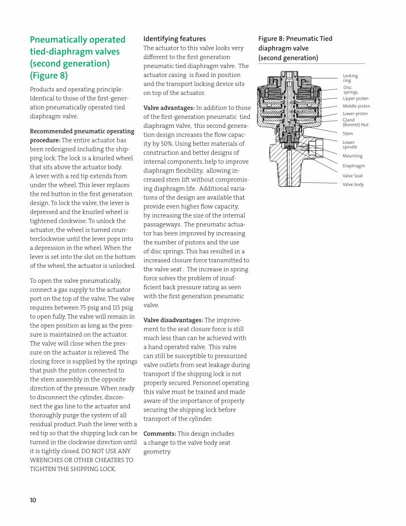
Identifying features The actuator to this valve looks very different to the first generation pneumatic tied diaphragm valve. The actuator casing is fixed in position and the transport locking device sits on top of the actuator.
Valve advantages: In addition to those of the first‑generation pneumatic tied diaphragm valve, this second genera‑tion design increases the flow capac‑ity by 50%. Using better materials of construction and better designs of internal components, help to improve diaphragm flexibility, allowing in‑creased stem lift without compromis‑ing diaphragm life. Additional varia‑tions of the design are available that provide even higher flow capacity, by increasing the size of the internal passageways. The pneumatic actua‑tor has been improved by increasing the number of pistons and the use of disc springs. This has resulted in a increased closure force transmitted to the valve seat . The increase in spring force solves the problem of insuf‑ficient back pressure rating as seen with the first generation pneumatic valve.
Valve disadvantages: The improve‑ment to the seat closure force is still much less than can be achieved with a hand operated valve. This valve can still be susceptible to pressurized valve outlets from seat leakage during transport if the shipping lock is not properly secured. Personnel operating this valve must be trained and made aware of the importance of properly securing the shipping lock before transport of the cylinder.
Comments: This design includes a change to the valve body seat geometry.
Pneumatically operated tied-diaphragm valves (second generation) (Figure 8)Products and operating principle: Identical to those of the first‑gener‑ation pneumatically operated tied diaphragm valve.
Recommended pneumatic operating procedure: The entire actuator has been redesigned including the ship‑ping lock. The lock is a knurled wheel that sits above the actuator body. A lever with a red tip extends from under the wheel. This lever replaces the red button in the first generation design. To lock the valve, the lever is depressed and the knurled wheel is tightened clockwise. To unlock the actuator, the wheel is turned coun‑terclockwise until the lever pops into a depression in the wheel. When the lever is set into the slot on the bottom of the wheel, the actuator is unlocked.
To open the valve pneumatically, connect a gas supply to the actuator port on the top of the valve. The valve requires between 75 psig and 115 psig to open fully. The valve will remain in the open position as long as the pres‑sure is maintained on the actuator. The valve will close when the pres‑sure on the actuator is relieved. The closing force is supplied by the springs that push the piston connected to the stem assembly in the opposite direction of the pressure. When ready to disconnect the cylinder, discon‑nect the gas line to the actuator and thoroughly purge the system of all residual product. Push the lever with a red tip so that the shipping lock can be turned in the clockwise direction until it is tightly closed. DO NOT USE ANY WRENCHES OR OTHER CHEATERS TO TIGHTEN THE SHIPPING LOCK.
The handwheel operated Tied-Diaphragm Valve (third generation) (figure 9)Products, operating principle, rec‑ommended opening and closing procedures: Identical to those of the first‑generation handwheel operated tied diaphragm valve.
Identifying features In addition to those of the first‑generation handwheel operated tied diaphragm valve, this valve can be identified by its thin stainless steel ring fitted over the gland nut.
Valve advantages: In addition to those of the second generation handwheel operated tied diaphragm valve, the valve seat seal is improved by the potential for it to become a dual soft seal and metal‑metal seal. Therefore, extrusion of the soft seat is prevented. The handwheel is designed to break in the event of excessive applied torque. The operating torque is further im‑proved by the addition of a ball bear‑ing at the base of the upper spindle. The valve is suited to oxidizer service, where there is always a possibility of soft seat burn out.
Comments: For valves used in oxidizer service, some of the improvement in operating torque, is reduced, due to the need to use oxidizer compat‑ible grease within the upper works of the valve. For these applications, recommended closing torque range is between 5 to 7ft lbs (7 to 10 Nm). The closing torque shall never exceed 11 ft‑lbs (15 Nm) in order to prevent seat damage.
Valve optionsConnections: The tied‑diaphragm valve and certain other valves are available with any of the standard cylinder valve connections or with the high leak integrity cylinder valve connections also known as DISS (Diameter Index Safety System) con‑nections. See Safetygram 31, “Cylinder Valve Connections,” for more information.
Restrictive flow orifices (RFO): An RFO is a small plug that screws into the valve outlet. It has a hole in the middle that can be anywhere be‑tween 0.006 to 0.16 inches in diam‑eter. The purpose of the RFO is to restrict the amount of flow that can come from the cylinder in the event of a system failure downstream. There are recommended sizes for most products, but customers can specify their requirements. Many variables must be taken into account when determining the size of an RFO, such as pressure of product, reactivity of product, and flow required by the pro‑cess. Safetygram 46, A Practical Guide to Restrictive Flow Orifices contains additional information
Corporate Headquarters Air Products and Chemicals, Inc. 1940 Air Products Blvd. Allentown, PA 18106-5500 T: 610-481-4911
Emergency Response SystemT 800-523-9374 (Continental U.S. and Puerto Rico)T +1-610-481-7711 (other locations) – for regional ER telephone numbers please refer to the local SDS 24 hours a day, 7 days a week for assistance involving Air Products and Chemicals, Inc. products